EP1128477A2 - Electrical connector with compression contacts - Google Patents
Electrical connector with compression contacts Download PDFInfo
- Publication number
- EP1128477A2 EP1128477A2 EP01103647A EP01103647A EP1128477A2 EP 1128477 A2 EP1128477 A2 EP 1128477A2 EP 01103647 A EP01103647 A EP 01103647A EP 01103647 A EP01103647 A EP 01103647A EP 1128477 A2 EP1128477 A2 EP 1128477A2
- Authority
- EP
- European Patent Office
- Prior art keywords
- contacts
- recited
- electrical connector
- housing
- contact
- Prior art date
- Legal status (The legal status is an assumption and is not a legal conclusion. Google has not performed a legal analysis and makes no representation as to the accuracy of the status listed.)
- Granted
Links
Images


Classifications
-
- H—ELECTRICITY
- H01—ELECTRIC ELEMENTS
- H01R—ELECTRICALLY-CONDUCTIVE CONNECTIONS; STRUCTURAL ASSOCIATIONS OF A PLURALITY OF MUTUALLY-INSULATED ELECTRICAL CONNECTING ELEMENTS; COUPLING DEVICES; CURRENT COLLECTORS
- H01R13/00—Details of coupling devices of the kinds covered by groups H01R12/70 or H01R24/00 - H01R33/00
- H01R13/02—Contact members
- H01R13/22—Contacts for co-operating by abutting
- H01R13/24—Contacts for co-operating by abutting resilient; resiliently-mounted
- H01R13/2442—Contacts for co-operating by abutting resilient; resiliently-mounted with a single cantilevered beam
-
- H—ELECTRICITY
- H01—ELECTRIC ELEMENTS
- H01R—ELECTRICALLY-CONDUCTIVE CONNECTIONS; STRUCTURAL ASSOCIATIONS OF A PLURALITY OF MUTUALLY-INSULATED ELECTRICAL CONNECTING ELEMENTS; COUPLING DEVICES; CURRENT COLLECTORS
- H01R12/00—Structural associations of a plurality of mutually-insulated electrical connecting elements, specially adapted for printed circuits, e.g. printed circuit boards [PCB], flat or ribbon cables, or like generally planar structures, e.g. terminal strips, terminal blocks; Coupling devices specially adapted for printed circuits, flat or ribbon cables, or like generally planar structures; Terminals specially adapted for contact with, or insertion into, printed circuits, flat or ribbon cables, or like generally planar structures
- H01R12/70—Coupling devices
- H01R12/71—Coupling devices for rigid printing circuits or like structures
- H01R12/712—Coupling devices for rigid printing circuits or like structures co-operating with the surface of the printed circuit or with a coupling device exclusively provided on the surface of the printed circuit
- H01R12/714—Coupling devices for rigid printing circuits or like structures co-operating with the surface of the printed circuit or with a coupling device exclusively provided on the surface of the printed circuit with contacts abutting directly the printed circuit; Button contacts therefore provided on the printed circuit
-
- H—ELECTRICITY
- H01—ELECTRIC ELEMENTS
- H01R—ELECTRICALLY-CONDUCTIVE CONNECTIONS; STRUCTURAL ASSOCIATIONS OF A PLURALITY OF MUTUALLY-INSULATED ELECTRICAL CONNECTING ELEMENTS; COUPLING DEVICES; CURRENT COLLECTORS
- H01R43/00—Apparatus or processes specially adapted for manufacturing, assembling, maintaining, or repairing of line connectors or current collectors or for joining electric conductors
- H01R43/20—Apparatus or processes specially adapted for manufacturing, assembling, maintaining, or repairing of line connectors or current collectors or for joining electric conductors for assembling or disassembling contact members with insulating base, case or sleeve
- H01R43/205—Apparatus or processes specially adapted for manufacturing, assembling, maintaining, or repairing of line connectors or current collectors or for joining electric conductors for assembling or disassembling contact members with insulating base, case or sleeve with a panel or printed circuit board
-
- H—ELECTRICITY
- H01—ELECTRIC ELEMENTS
- H01R—ELECTRICALLY-CONDUCTIVE CONNECTIONS; STRUCTURAL ASSOCIATIONS OF A PLURALITY OF MUTUALLY-INSULATED ELECTRICAL CONNECTING ELEMENTS; COUPLING DEVICES; CURRENT COLLECTORS
- H01R12/00—Structural associations of a plurality of mutually-insulated electrical connecting elements, specially adapted for printed circuits, e.g. printed circuit boards [PCB], flat or ribbon cables, or like generally planar structures, e.g. terminal strips, terminal blocks; Coupling devices specially adapted for printed circuits, flat or ribbon cables, or like generally planar structures; Terminals specially adapted for contact with, or insertion into, printed circuits, flat or ribbon cables, or like generally planar structures
- H01R12/70—Coupling devices
- H01R12/71—Coupling devices for rigid printing circuits or like structures
- H01R12/712—Coupling devices for rigid printing circuits or like structures co-operating with the surface of the printed circuit or with a coupling device exclusively provided on the surface of the printed circuit
- H01R12/716—Coupling device provided on the PCB
Definitions
- the present invention relates to electrical connectors. More specifically, the present invention relates to mezzanine-style electrical connectors using compression contacts to interconnect a first electrical component to a second electrical component.
- U.S. Patent number 5,484,295 describes a typical compression connector.
- Typical compression connectors have contacts with medial sections retained within a housing. Depending upon the application, the contact has at least one arm extending from the medial section in cantilevered fashion to engage an electrical component. Such connectors may not provide suitable wiping action or contact normal force.
- an electrical connector comprising: a housing having a retention structure; and a plurality of contacts extending through the housing.
- Each contact has: a medial section; a mounting portion extending from one end of the medial section; and a compressive mating portion extending from another end of the medial section and having a distal end.
- the retention structure of the housing engages the distal ends of the compressive mating portions of the contacts to preload the contacts.
- an electrical connector comprising: a housing; a plurality of contacts extending through the housing and exhibiting a preload; and a plurality of fusible elements, each secured to a respective one of the contacts.
- a method of making an electrical connector comprising the steps of: providing a housing; inserting a plurality of contacts into the housing; securing a fusible element to each contact; and preloading the contacts.
- Figures 1-5 display one alternative embodiment of the present invention. Specifically, Figure 1 shows a perspective view of an electrical connector 100, Figure 2 shows a top view of the connector 100, and Figure 3 shows a bottom view of the connector 100.
- Connector 100 comprises a housing 101, contacts 103, and fusible elements 105, described in further detail below.
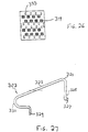
- FIG 4 A side view of the electrical connector 100 with one fusible element 105 secured to a contact 103 is shown in Figure 4, and Figure 5 is a front view of the electrical connector 100 with fusible elements 105 secured to all of the contacts 103.
- Connector 100 preferably surface mounts to a first substrate Sl and engages a second substrate S2.
- Substrates S1, S2 could be, for example, printed circuit boards (PCBs) or land grid arrays (LGAs).
- FIG 6 is a perspective view of a housing 101
- Figure 7 is a top view of the housing 101
- Figures 8, 9 and 10 are cross-sectional views of the housing 101 taken along lines VIII-VIII, IX-IX, and X-X, respectively, in Figure 7.
- Housing 101 can be a suitable insulative material, such as a high temperature thermoplastic like liquid crystal polymer (LCP).
- LCP high temperature thermoplastic like liquid crystal polymer
- housing 101 is made by injection molding.
- Housing 101 includes alignment posts 107, 109 to help position substrate S2 relative to connector 100. Housing 101 also has openings 111 through which contacts 103 extend. Each opening 111 can have retention features, such as projections 113 which engage contacts 103 by an interference fit. Projections 113 help retain contacts 103 within housing 101 until fusible elements 105 secure to contacts 103.
- Housing 101 also includes a channel 115 for each contact 103.
- Channels 115 helps guide contact 103 when connector 100 mates with substrate S2. Specifically, as substrate S2 approaches and eventually engages connector 100, contacts 103 compress. During compression, channels 115 prevent undesired movement of contacts 103.
- Openings 117 in the side wall of housing 101 communicate with corresponding channels 115. Openings 117 receive the distal end of contact 103. Due to the size of housing 101 and contact 103, openings 117 provide a preload to contacts 103. The preload helps ensure that contacts 103 provide adequate normal force when connector 100 mates with substrate S2.
- connector 100 can surface mount to substrate S1.
- connector 100 surface mounts using a fusible element 105, such as a solder ball.
- housing 101 could have recesses 119 in communication with openings 111. Each recess 119 could receive a portion of a respective fusible element 105.
- One or more reflow steps could secure fusible element 105 to contact 103 and secure connector 101 to substrate S1.
- International Publication Number WO 98/15989 herein incorporated by reference, describes methods of securing a solder ball to a contact and to a substrate.
- recesses 119 are staggered on housing 101. Staggering fusible elements 105 helps connector 100 achieve a fine pitch (such as approximately 1mm or less, for example).
- FIG 12 is a side view of a contact 103
- Figure 13 is a top view of the contact 103
- Figure 14 is a front view of the contact 103.
- Contact 103 is preferably stamped and formed from a suitable sheet of conductive material, such as copper alloy.
- contact 103 has a compressive section with a mating area 121 flanked by an arm 123 and a tab 125. Arm 123 angularly deflects when connector mates with substrate S1.
- Tab 125 provides the preload to contact 103.
- tab 125 has ears 127 extending therefrom. While the remainder of contact 103 can move through opening 117, ears 127 cannot.
- contact 103 must be compressed to insert tab 125 into opening 117.
- ears 127 prevent contact 103 from returning to an unloaded state. In other words, contact 103 remains preloaded in housing 101.
- Contact 103 also has an end opposite the compressive section. Contact 103 could have compressive sections at both ends. In the embodiment shown in the drawings, however, the end is a surface mount termination. Specifically, contact 103 has a mounting tab 129.
- a bend 131 resides between mounting tab 129 and the compressive section. Bend 131 ensures adequate wiping action and provides the contact normal force to connector 100.
- Figure 15 is a perspective view of the electrical connector shown 100 covered with a vacuum pickup cap 200, and placed upon a circuit substrate S1.
- Figure 16 is a top view of the vacuum pickup cap 200 and
- Figure 17 is a side view of the vacuum pickup cap 200.
- Cap 200 allows automated placement of connector 100 on substrate S1. Automated placement help ensure proper alignment of fusible elements 105 with a corresponding trace T on substrate S1.
- Cap 200 has an upper wall 201 with side walls 203 extending therefrom. Side walls 203 can have latches 205 which engage suitable latch structure, such as notches 133 in housing 101. As seen in Figure 15, side walls 203 rest on the upper face of housing 101. That way, cap 200 does not interfere with contacts 103.
- Figure 18 is a perspective view of another alternative embodiment of an electrical connector 300 of the present invention and Figure 19 is a top view of the electrical connector 300.
- Figure 20 is a side view of the electrical connector 300 with fusible elements 105 secured to associated contacts 303
- Figure 21 is a front view of the electrical connector 300 with fusible elements 105 secured to all of the contacts 303.
- Figures 18-29 contain elements similar to those described above with respect to Figures 1-17. These elements are labeled identically and their description is omitted for brevity.
- connector 300 A difference between connector 300 and connector 100 is the number of rows of mating areas 321. Whereas connector 100 has two rows of mating areas 121, connector 300 has four rows of mating areas 321. More particularly, contacts 303 are placed front to back, so instead of two rows of top mating areas (e.g., mating areas 121), there are now four rows of top mating areas 321. Although two rows and four rows of contacts are described herein, it is contemplated that the connector of the present invention could have any number of rows of contacts.
- FIG 22 is a more detailed view of an exemplary electrical connector 300 in accordance with the present invention
- Figure 23 is a corresponding side view.
- the contacts 303 are arranged so that the mating areas 321 of neighboring contacts are disposed at opposing ends.
- neighboring contacts are oriented in opposite directions.
- each mating area 321 in a row of mating areas is separated from the next mating area 321 in that row by the end of a contact 303 that does not contain a mating area 321. This leads to a very compact connector.
- the contacts 303 can be disposed in other arrangements, such as that shown in Figures 24 and 25, for example. In this embodiment, there are four rows of mating areas 321 of contacts 303. However, unlike the connector of Figure 22, the contacts 303 are all oriented in the same direction, though they are in a similar staggered arrangement.
- housing 301 includes an opening 333, as shown in Figure 26, for each tab portion 325 of contact 303.
- housing 301 has retentive features which engage the distal end and prevent contact 303 from returning to an unloaded condition after insertion into housing 301.
- the retentive feature could be a shoulder within opening 333 that blocks the distal end.
- the contact pads are offset, as shown in Figures 22 and 26, for example.
- the top and bottom attachment locations are obtained by staggering and rotating contacts 180 degrees in an alternating manner. This offset allows for more side-to-side and front-to-back float, and a larger top circuit board pad to accommodate this float.
- alignment posts e.g., posts 107, 109 are not used. By removing the alignment posts, the potential for (1) the top circuit board alignment, (2) thermal stress or (3) mechanical stress being transferred from the top circuit board through the alignment posts and to the solder attachment is reduced. Removal of the posts also allows for housing size to be decreased.
- Figure 23 is a side view of a contact 303.
- the contact 303 uses a tapered cantilever beam for maximum deflection with uniform stress distribution.
- contact 303 is preferably stamped and formed from a suitable sheet of conductive material, such as copper alloy.
- contact 303 has a compressive section with a mating area 321 flanked by an arm 323 and a tab 325.
- Tab 325 provides the preload to contact 303, and has a projection 327 extending therefrom.
- Arm 323 angularly deflects when connector mates with substrate S1.
- Contact 303 also has an end opposite the compressive section. Contact 303 could have compressive sections at both ends. In the embodiment shown in the drawings, however, the end is a surface mount termination. Specifically, contact 303 has a mounting tab 329.
- contacts 303 During insertion into housing 301, contacts 303 must be compressed to insert tab 325 into opening 333. Upon complete insertion, projection 327 prevents contact 303 from returning to an unloaded state. In other words, contact 303 remains preloaded in housing 301.
- a bend 331 resides between mounting tab 329 and the compressive section. Bend 331 ensures adequate wiping action and provides the contact normal force to connector 300.
- all contacts are assembled from the top and use standard solder ball attachment process.
- the solder ball recess 319 has been modified so that the rear contact surface rests on a flat surface and the front contact surface interferes with the housing bump. This allows for more consistent contact positioning because the bump only compresses on one side instead of both sides.
- Figure 28 is a perspective view of the electrical connector 300, covered with a vacuum pickup cap 400, and placed upon a circuit substrate S1
- Figure 29 is a side view of the electrical connector 300, cap 400, and substrate S1. Similar to cap 200, cap 400 allows automated placement of connector 300 on substrate S1. Automated placement helps ensure proper alignment of fusible elements 305 with a corresponding trace T on substrate S1.
- Cap 400 has an upper wall 401 with side walls 403 extending therefrom. Side walls 403 can have latches 405 which engage suitable latch structure, such as notches 334 in housing 301. As seen in Figure 29, side walls 403 rest on the upper face of housing 301. That way, cap 400 does not interfere with contacts 303.
Abstract
Description
- This application claims the benefit of U.S. Provisional Application Serial Number 60/184,607, which was filed on 24 February 2000, herein incorporated by reference.
- The present invention relates to electrical connectors. More specifically, the present invention relates to mezzanine-style electrical connectors using compression contacts to interconnect a first electrical component to a second electrical component.
- U.S. Patent number 5,484,295 describes a typical compression connector. Typical compression connectors have contacts with medial sections retained within a housing. Depending upon the application, the contact has at least one arm extending from the medial section in cantilevered fashion to engage an electrical component. Such connectors may not provide suitable wiping action or contact normal force.
- It is an object of the present invention to provide an electrical connector with suitable wiping action.
- It is a further object of the present invention to provide an electrical connector with suitable contact normal force.
- It is a further object of the present invention to provide a surface mounted compression connector.
- It is a further object of the present invention to provide a compression connector with preloaded contacts.
- These and other objects of the present invention are achieved in one aspect of the present invention by an electrical connector, comprising: a housing having a retention structure; and a plurality of contacts extending through the housing. Each contact has: a medial section; a mounting portion extending from one end of the medial section; and a compressive mating portion extending from another end of the medial section and having a distal end. The retention structure of the housing engages the distal ends of the compressive mating portions of the contacts to preload the contacts.
- These and other objects of the present invention are achieved in another aspect of the present invention by an electrical connector, comprising: a housing; a plurality of contacts extending through the housing and exhibiting a preload; and a plurality of fusible elements, each secured to a respective one of the contacts.
- These and other objects of the present invention are achieved in another aspect of the present invention by a method of making an electrical connector, comprising the steps of: providing a housing; inserting a plurality of contacts into the housing; securing a fusible element to each contact; and preloading the contacts.
- Other uses and advantages of the present invention will become apparent to those skilled in the art upon reference to the specification and the drawings, in which:
- Figure 1 is a perspective view of a first alternative embodiment of an electrical connector of the present invention;
- Figure 2 is a top view of the electrical connector shown in Figure 1;
- Figure 3 is a bottom view of the electrical connector shown in Figure 1 with one fusible element secured to a contact;
- Figure 4 is a side view of the electrical connector shown in Figure 1 with one fusible element secured to a contact;
- Figure 5 is a front view of the electrical connector shown in Figure 1 with fusible elements secured to all of the contacts;
- Figure 6 is a perspective view of a housing, which is one component of the electrical connector shown in Figure 1;
- Figure 7 is a top view of the housing shown in Figure 6;
- Figure 8 is a cross-sectional view of the housing taken along line VIII-VIII in Figure 7;
- Figure 9 is a cross-sectional view of the housing taken along line IX-IX in Figure 7;
- Figure 10 is a cross-sectional view of the housing taken along line X-X in Figure 7;
- Figure 11 is a cross-sectional view of the electrical connector, partially assembled, taken along lines XI-XI of Figure 3;
- Figure 12 is a side view of a contact, which is one component of the electrical connector shown in Figure 1;
- Figure 13 is a top view of the contact shown in Figure 12;
- Figure 14 is a front view of the contact shown in Figure 12;
- Figure 15 is a perspective view of the electrical connector shown in Figure 1, covered with a vacuum pickup cap, and placed upon a circuit substrate;
- Figure 16 is a top view of the vacuum pickup cap shown in Figure 15;
- Figure 17 is a side view of the vacuum pickup cap shown in Figure 15;
- Figure 18 is a perspective view of another alternative embodiment of an electrical connector of the present invention;
- Figure 19 is a top view of the electrical connector shown in Figure 18;
- Figure 20 is a side view of the electrical connector shown in Figure 18 with fusible elements secured to associated contacts;
- Figure 21 is a front view of the electrical connector shown in Figure 18 with fusible elements secured to all of the contacts;
- Figure 22 is an enlarged top view of the connector shown in Figure 18;
- Figure 23 is a side view of the electrical connector shown in Figure 22;
- Figure 24 is a top view of another exemplary electrical connector in accordance with the present invention;
- Figure 25 is a side view of the electrical connector shown in Figure 24;
- Figure 26 is a bottom view of the electrical connector shown in Figure 18;
- Figure 27 is a side view of a contact, which is one component of the electrical connector shown in Figure 18;
- Figure 28 is a perspective view of the electrical connector shown in Figure 18, covered with a vacuum pickup cap, and placed upon a circuit substrate; and
- Figure 29 is a side view of the electrical connector, cap, and substrate of Figure 28.
-
- Figures 1-5 display one alternative embodiment of the present invention. Specifically, Figure 1 shows a perspective view of an
electrical connector 100, Figure 2 shows a top view of theconnector 100, and Figure 3 shows a bottom view of theconnector 100.Connector 100 comprises ahousing 101,contacts 103, andfusible elements 105, described in further detail below. - A side view of the
electrical connector 100 with onefusible element 105 secured to acontact 103 is shown in Figure 4, and Figure 5 is a front view of theelectrical connector 100 withfusible elements 105 secured to all of thecontacts 103.Connector 100 preferably surface mounts to a first substrate Sl and engages a second substrate S2. Substrates S1, S2 could be, for example, printed circuit boards (PCBs) or land grid arrays (LGAs). - Figure 6 is a perspective view of a
housing 101, Figure 7 is a top view of thehousing 101, and Figures 8, 9 and 10 are cross-sectional views of thehousing 101 taken along lines VIII-VIII, IX-IX, and X-X, respectively, in Figure 7.Housing 101 can be a suitable insulative material, such as a high temperature thermoplastic like liquid crystal polymer (LCP). Preferably,housing 101 is made by injection molding. -
Housing 101 includesalignment posts connector 100.Housing 101 also hasopenings 111 through whichcontacts 103 extend. Eachopening 111 can have retention features, such asprojections 113 which engagecontacts 103 by an interference fit.Projections 113 help retaincontacts 103 withinhousing 101 untilfusible elements 105 secure tocontacts 103. -
Housing 101 also includes achannel 115 for eachcontact 103.Channels 115 helps guidecontact 103 whenconnector 100 mates with substrate S2. Specifically, as substrate S2 approaches and eventually engagesconnector 100,contacts 103 compress. During compression,channels 115 prevent undesired movement ofcontacts 103. -
Openings 117 in the side wall ofhousing 101 communicate withcorresponding channels 115.Openings 117 receive the distal end ofcontact 103. Due to the size ofhousing 101 and contact 103,openings 117 provide a preload tocontacts 103. The preload helps ensure thatcontacts 103 provide adequate normal force whenconnector 100 mates with substrate S2. - If desired,
connector 100 can surface mount to substrate S1. Preferably,connector 100 surface mounts using afusible element 105, such as a solder ball. In order to assist the mounting offusible element 105,housing 101 could haverecesses 119 in communication withopenings 111. Eachrecess 119 could receive a portion of a respectivefusible element 105. One or more reflow steps could securefusible element 105 to contact 103 andsecure connector 101 to substrate S1. International Publication Number WO 98/15989, herein incorporated by reference, describes methods of securing a solder ball to a contact and to a substrate. - As seen in Figure 3, recesses 119 are staggered on
housing 101. Staggeringfusible elements 105 helpsconnector 100 achieve a fine pitch (such as approximately 1mm or less, for example). - Figure 12 is a side view of a
contact 103, Figure 13 is a top view of thecontact 103, and Figure 14 is a front view of thecontact 103. Contact 103 is preferably stamped and formed from a suitable sheet of conductive material, such as copper alloy. In this embodiment, contact 103 has a compressive section with amating area 121 flanked by anarm 123 and atab 125.Arm 123 angularly deflects when connector mates with substrate S1.Tab 125 provides the preload to contact 103. Specifically,tab 125 hasears 127 extending therefrom. While the remainder ofcontact 103 can move throughopening 117,ears 127 cannot. During insertion intohousing 101, contact 103 must be compressed to inserttab 125 intoopening 117. Upon complete insertion, however,ears 127 preventcontact 103 from returning to an unloaded state. In other words, contact 103 remains preloaded inhousing 101. - Contact 103 also has an end opposite the compressive section. Contact 103 could have compressive sections at both ends. In the embodiment shown in the drawings, however, the end is a surface mount termination. Specifically, contact 103 has a mounting
tab 129. - A
bend 131 resides between mountingtab 129 and the compressive section.Bend 131 ensures adequate wiping action and provides the contact normal force toconnector 100. - Figure 15 is a perspective view of the electrical connector shown 100 covered with a
vacuum pickup cap 200, and placed upon a circuit substrate S1. Figure 16 is a top view of thevacuum pickup cap 200 and Figure 17 is a side view of thevacuum pickup cap 200.Cap 200 allows automated placement ofconnector 100 on substrate S1. Automated placement help ensure proper alignment offusible elements 105 with a corresponding trace T on substrate S1. -
Cap 200 has anupper wall 201 withside walls 203 extending therefrom.Side walls 203 can havelatches 205 which engage suitable latch structure, such asnotches 133 inhousing 101. As seen in Figure 15,side walls 203 rest on the upper face ofhousing 101. That way,cap 200 does not interfere withcontacts 103. - Figure 18 is a perspective view of another alternative embodiment of an
electrical connector 300 of the present invention and Figure 19 is a top view of theelectrical connector 300. Figure 20 is a side view of theelectrical connector 300 withfusible elements 105 secured to associatedcontacts 303, and Figure 21 is a front view of theelectrical connector 300 withfusible elements 105 secured to all of thecontacts 303. Figures 18-29 contain elements similar to those described above with respect to Figures 1-17. These elements are labeled identically and their description is omitted for brevity. - A difference between
connector 300 andconnector 100 is the number of rows ofmating areas 321. Whereasconnector 100 has two rows ofmating areas 121,connector 300 has four rows ofmating areas 321. More particularly,contacts 303 are placed front to back, so instead of two rows of top mating areas (e.g., mating areas 121), there are now four rows oftop mating areas 321. Although two rows and four rows of contacts are described herein, it is contemplated that the connector of the present invention could have any number of rows of contacts. - Figure 22 is a more detailed view of an exemplary
electrical connector 300 in accordance with the present invention, and Figure 23 is a corresponding side view. As shown, there are four rows ofmating areas 321 ofcontacts 303. In this example, thecontacts 303 are arranged so that themating areas 321 of neighboring contacts are disposed at opposing ends. In other words, neighboring contacts are oriented in opposite directions. In this manner, eachmating area 321 in a row of mating areas is separated from thenext mating area 321 in that row by the end of acontact 303 that does not contain amating area 321. This leads to a very compact connector. - The
contacts 303 can be disposed in other arrangements, such as that shown in Figures 24 and 25, for example. In this embodiment, there are four rows ofmating areas 321 ofcontacts 303. However, unlike the connector of Figure 22, thecontacts 303 are all oriented in the same direction, though they are in a similar staggered arrangement. - Another difference between
connector 300 andconnector 100 is the preloading ofcontacts connector 100,openings 117 extend along an outside perimeter ofhousing 101 for receiving thetab 125 ofcontact 103. Becauseconnector 300 has four rows,housing 301 must have a different arrangement. Accordingly,housing 301 includes anopening 333, as shown in Figure 26, for eachtab portion 325 ofcontact 303. Within opening 333,housing 301 has retentive features which engage the distal end and preventcontact 303 from returning to an unloaded condition after insertion intohousing 301. For example, the retentive feature could be a shoulder within opening 333 that blocks the distal end. - In these embodiments, the contact pads are offset, as shown in Figures 22 and 26, for example. The top and bottom attachment locations are obtained by staggering and rotating contacts 180 degrees in an alternating manner. This offset allows for more side-to-side and front-to-back float, and a larger top circuit board pad to accommodate this float.
- Moreover, in this embodiment, alignment posts (e.g., posts 107, 109) are not used. By removing the alignment posts, the potential for (1) the top circuit board alignment, (2) thermal stress or (3) mechanical stress being transferred from the top circuit board through the alignment posts and to the solder attachment is reduced. Removal of the posts also allows for housing size to be decreased.
- Figure 23 is a side view of a
contact 303. Thecontact 303 uses a tapered cantilever beam for maximum deflection with uniform stress distribution. Likecontact 103, contact 303 is preferably stamped and formed from a suitable sheet of conductive material, such as copper alloy. In this embodiment, contact 303 has a compressive section with amating area 321 flanked by anarm 323 and atab 325.Tab 325 provides the preload to contact 303, and has aprojection 327 extending therefrom.Arm 323 angularly deflects when connector mates with substrate S1. - Contact 303 also has an end opposite the compressive section. Contact 303 could have compressive sections at both ends. In the embodiment shown in the drawings, however, the end is a surface mount termination. Specifically, contact 303 has a mounting
tab 329. - During insertion into
housing 301,contacts 303 must be compressed to inserttab 325 intoopening 333. Upon complete insertion,projection 327 prevents contact 303 from returning to an unloaded state. In other words, contact 303 remains preloaded inhousing 301. - A
bend 331 resides between mountingtab 329 and the compressive section.Bend 331 ensures adequate wiping action and provides the contact normal force toconnector 300. - Preferably, all contacts are assembled from the top and use standard solder ball attachment process. The
solder ball recess 319 has been modified so that the rear contact surface rests on a flat surface and the front contact surface interferes with the housing bump. This allows for more consistent contact positioning because the bump only compresses on one side instead of both sides. - Figure 28 is a perspective view of the
electrical connector 300, covered with avacuum pickup cap 400, and placed upon a circuit substrate S1, and Figure 29 is a side view of theelectrical connector 300,cap 400, and substrate S1. Similar to cap 200,cap 400 allows automated placement ofconnector 300 on substrate S1. Automated placement helps ensure proper alignment offusible elements 305 with a corresponding trace T on substrate S1. -
Cap 400 has anupper wall 401 withside walls 403 extending therefrom.Side walls 403 can havelatches 405 which engage suitable latch structure, such asnotches 334 inhousing 301. As seen in Figure 29,side walls 403 rest on the upper face ofhousing 301. That way,cap 400 does not interfere withcontacts 303. - While the present invention has been described in connection with the preferred embodiments of the various figures, it is to be understood that other similar embodiments may be used or modifications and additions may be made to the described embodiment for performing the same function of the present invention without deviating therefrom. Therefore, the present invention should not be limited to any single embodiment, but rather construed in breadth and scope in accordance with the recitation of the appended claims.
Claims (33)
- An electrical connector (100), comprising:a housing (101) having a retention structure; anda plurality of contacts (103) extending through said housing (101), each said contact including:a medial section;a mounting portion extending from one end of said medial section; anda compressive mating portion extending from another end of said medial section and having a distal end;wherein said retention structure of said housing engages said distal ends of said compressive mating portions of said contacts to preload said contacts.
- The electrical connector as recited in claim 1, further comprising a fusible element (105) secured to said mounting portion of said contact (103).
- The electrical connector as recited in claim 1 or 2, wherein said housing comprises alignment posts (107, 109).
- The electrical connector as recited in one of the preceding claims, wherein said retention structure comprises a plurality of projections (113) that engage associated contacts (103).
- The electrical connector as recited in one of the preceding claims, wherein said housing (101) comprises a plurality of channels (115) for receiving associated contacts (103).
- The electrical connector as recited in one of the preceding claims, wherein said contacts (103) are disposed at a pitch of approximately 1 mm or less.
- The electrical connector as recited in one of the preceding claims, further comprising a vacuum pickup cap (200) that engages said housing (101).
- The electrical connector as recited in one of the preceding claims, wherein said contacts are disposed so that neighboring contacts (103) are oriented in opposite directions in an alternating manner.
- The electrical connector as recited in one of the preceding claims, wherein said contacts (103) are oriented in the same direction.
- The electrical connector as recited in claim 9, wherein said contacts are disposed in a staggered arrangement.
- The electrical connector as recited in one of the preceding claims, wherein said retention structure comprises a plurality of shoulders that block associated distal ends of said contacts.
- The electrical connector as recited in one of the preceding claims, wherein said medial section of each said contact comprises a tapered cantilever beam.
- The electrical connector as recited in one of the preceding claims, wherein each mating portion is flanked by a tab providing a preload to said contact, said tab having a projection extending therefrom.
- The electrical connector as recited in one of the preceding claims, wherein said end of each said medial portion in which said mounting portion extends further comprises a compressive section.
- The electrical connector as recited in one of the preceding claims, further comprising a bend disposed between said medial section and said compressive mating portion, said bend providing said contact with normal force to said connector.
- An electrical connector (300), comprising:a housing (301);a plurality of contacts (303) extending through said housing and exhibiting a preload; anda plurality of fusible elements (305), each secured to a respective one of said contacts (300).
- The electrical connector as recited in claim 16, wherein said fusible element (305) is a solder body.
- The electrical connector as recited in claim 17, wherein said solder body is a solder ball.
- The electrical connector as recited in claim 16, wherein said housing (301) comprises a retention structure.
- The electrical connector (300) as recited in claim 19, wherein each said contact (303) includes:wherein said retention structure of said housing (301) engages said distal ends of said compressive mating portions of said contacts to preload said contacts (303).a medial section;a mounting portion extending from one end of said medial section; anda compressive mating portion (321) extending from another end of said medialsection and having a distal end,
- The electrical connector as recited in claim 16, wherein said contacts (303) are disposed so that neighboring contacts (303) are oriented in opposite directions in an alternating manner.
- The electrical connector as recited in claim 16, wherein said contacts (303) are oriented in the same direction.
- The electrical connector as recited in claim 22, wherein said contacts (303) are disposed in a staggered arrangement.
- The electrical connector as recited in claim 16, further comprising a vacuum pickup cap (400) that engages said housing.
- A method of making an electrical connector, comprising the steps of:providing a housing (101, 301);inserting a plurality of contacts (103, 303) into said housing;securing a fusible element (305) to each of said contacts (103, 303); andpreloading said contacts.
- The method as recited in claim 25, wherein the preloading step comprises engaging distal ends of said contacts with said housing (101, 301).
- The method as recited in claim 25, wherein inserting said plurality of contacts comprises engaging each said contact with an associated projection of said housing (101, 301).
- The method as recited in claim 25, wherein inserting said plurality of contacts comprises inserting said contacts (103, 303) into associated channels in said housing (101, 301).
- The method as recited in claim 25, wherein inserting said plurality of contacts into said housing comprises inserting said contacts (103, 303) so that neighboring contacts are oriented in opposite directions in an alternating manner.
- The method as recited in claim 25, wherein inserting said plurality of contacts into said housing (101, 301) comprises orienting said contacts in the same direction.
- The method as recited in claim 30, wherein inserting said plurality of contacts (103, 303) into said housing further comprises arranging said contacts in a staggered arrangement.
- The method as recited in claim 25, wherein inserting said plurality of contacts (103, 303) into said housing comprises compressing each contact to insert a tab into an associated opening in the housing.
- The method as recited in claim 25, further comprising latching a vacuum pickup cap (200, 400) to the housing.
Applications Claiming Priority (2)
| Application Number | Priority Date | Filing Date | Title |
|---|---|---|---|
| US18460700P | 2000-02-24 | 2000-02-24 | |
| US184607P | 2000-02-24 |
Publications (3)
| Publication Number | Publication Date |
|---|---|
| EP1128477A2 true EP1128477A2 (en) | 2001-08-29 |
| EP1128477A3 EP1128477A3 (en) | 2002-09-11 |
| EP1128477B1 EP1128477B1 (en) | 2009-12-02 |
Family
ID=22677601
Family Applications (1)
| Application Number | Title | Priority Date | Filing Date |
|---|---|---|---|
| EP01103647A Expired - Lifetime EP1128477B1 (en) | 2000-02-24 | 2001-02-22 | Electrical connector with compression contacts |
Country Status (8)
| Country | Link |
|---|---|
| US (1) | US6758702B2 (en) |
| EP (1) | EP1128477B1 (en) |
| JP (1) | JP2001266980A (en) |
| KR (1) | KR100669296B1 (en) |
| AT (1) | ATE450907T1 (en) |
| CA (1) | CA2337643A1 (en) |
| DE (1) | DE60140637D1 (en) |
| TW (1) | TW474469U (en) |
Families Citing this family (20)
| Publication number | Priority date | Publication date | Assignee | Title |
|---|---|---|---|---|
| US6994565B2 (en) * | 2003-07-14 | 2006-02-07 | Fci Americas Technology, Inc. | Electrical contact assembly with insulative carrier, stapled contact attachment and fusible element |
| US7156706B2 (en) * | 2003-07-22 | 2007-01-02 | Tyco Electronics Corporation | Contact having multiple contact beams |
| TWM266621U (en) * | 2004-08-02 | 2005-06-01 | Hon Hai Prec Ind Co Ltd | Land grid array electrical connector |
| US7381060B2 (en) * | 2006-05-25 | 2008-06-03 | Lotes Co., Ltd. | Electrical connector array |
| KR100679673B1 (en) * | 2006-10-30 | 2007-02-06 | 수공아이엔씨(주) | A filter assembly and wind-control device for clean room |
| CN201112761Y (en) * | 2007-07-19 | 2008-09-10 | 富士康(昆山)电脑接插件有限公司 | Electric connector |
| US7934961B2 (en) * | 2008-06-11 | 2011-05-03 | Tyco Electronics Corporation | Low profile contact |
| US7766668B1 (en) * | 2009-02-11 | 2010-08-03 | Avx Corporation | Low profile electrical conductor assembly for interconnecting conductive components in a stacked configuration |
| CN201667425U (en) * | 2009-11-20 | 2010-12-08 | 富士康(昆山)电脑接插件有限公司 | Electric connector |
| CN102201623B (en) * | 2010-03-24 | 2013-03-13 | 富士康(昆山)电脑接插件有限公司 | Electric connector |
| CN102315532B (en) * | 2010-06-30 | 2015-07-08 | 富士康(昆山)电脑接插件有限公司 | Electric connector |
| JP2012018892A (en) * | 2010-07-09 | 2012-01-26 | Tyco Electronics Japan Kk | Electrical component |
| TWM402514U (en) * | 2010-09-09 | 2011-04-21 | Hon Hai Prec Ind Co Ltd | Electrical connector |
| US8079851B1 (en) * | 2010-11-11 | 2011-12-20 | Hon Hai Precision Ind. Co., Ltd. | Socket with lower contact |
| JP5717472B2 (en) * | 2011-03-07 | 2015-05-13 | 富士通コンポーネント株式会社 | connector |
| DE102012103689A1 (en) * | 2012-04-26 | 2013-10-31 | Conti Temic Microelectronic Gmbh | Electric connector for use in electrical connector assembly for connecting two printed circuit boards, has spring contacts arranged to form successive sequence at same position, where contact ends are formed mutually parallel to each other |
| JP2014060120A (en) * | 2012-09-19 | 2014-04-03 | Tyco Electronics Japan Kk | Holding structure of contact |
| DE102015110498B3 (en) * | 2015-06-30 | 2016-11-17 | HARTING Electronics GmbH | Sliding element for contacting printed circuit boards |
| CN206532926U (en) * | 2017-01-18 | 2017-09-29 | 番禺得意精密电子工业有限公司 | Electric connector |
| US10553971B1 (en) * | 2019-01-08 | 2020-02-04 | Te Connectivity Corporation | Card edge connector having a contact positioner |
Citations (1)
| Publication number | Priority date | Publication date | Assignee | Title |
|---|---|---|---|---|
| EP0568971A1 (en) | 1992-05-08 | 1993-11-10 | Molex Incorporated | Electrical connector with contact anti-overstress means |
Family Cites Families (43)
| Publication number | Priority date | Publication date | Assignee | Title |
|---|---|---|---|---|
| JPS5257428Y2 (en) * | 1974-04-11 | 1977-12-26 | ||
| US4220383A (en) * | 1979-04-06 | 1980-09-02 | Amp Incorporated | Surface to surface connector |
| US4370017A (en) * | 1980-11-20 | 1983-01-25 | Amp Incorporated | Complanate contact terminal |
| US4354729A (en) * | 1980-12-22 | 1982-10-19 | Amp Incorporated | Preloaded electrical contact terminal |
| JPS63274074A (en) * | 1987-05-01 | 1988-11-11 | アンプ インコ−ポレ−テツド | Printed board connector |
| US5139427A (en) | 1991-09-23 | 1992-08-18 | Amp Incorporated | Planar array connector and flexible contact therefor |
| US5306163A (en) | 1991-10-30 | 1994-04-26 | Molex Incorporated | Destaticized connector structure |
| US5259769A (en) * | 1992-09-29 | 1993-11-09 | Molex Incorporated | Electrical connector with preloaded spring-like terminal with improved wiping action |
| BR9405792A (en) * | 1993-12-23 | 1995-12-19 | Motorola Inc | Double beam contact for making connection and double beam contact for making electrical connection |
| FR2714539B1 (en) * | 1993-12-24 | 1996-01-26 | Itt Composants Instr | Electrical connector for the connection of an electronic memory card. |
| US5800184A (en) | 1994-03-08 | 1998-09-01 | International Business Machines Corporation | High density electrical interconnect apparatus and method |
| US5484295A (en) | 1994-04-01 | 1996-01-16 | Teledyne Electronic Technologies | Low profile compression electrical connector |
| GB9513540D0 (en) * | 1995-07-04 | 1995-09-06 | Elco Europ Ltd | Electrical connectors |
| US5810609A (en) | 1995-08-28 | 1998-09-22 | Tessera, Inc. | Socket for engaging bump leads on a microelectronic device and methods therefor |
| US5653598A (en) | 1995-08-31 | 1997-08-05 | The Whitaker Corporation | Electrical contact with reduced self-inductance |
| JPH0982431A (en) | 1995-09-19 | 1997-03-28 | Whitaker Corp:The | Electric connector and its preparation |
| GB9519204D0 (en) | 1995-09-20 | 1995-11-22 | Amp Gmbh | Electrical installataion bus connector |
| US5655913A (en) | 1995-09-26 | 1997-08-12 | Motorola, Inc. | Electrical interconnect contact |
| US5746608A (en) * | 1995-11-30 | 1998-05-05 | Taylor; Attalee S. | Surface mount socket for an electronic package, and contact for use therewith |
| US5879169A (en) | 1996-03-18 | 1999-03-09 | Hon Hai Precision Ind. Co., Ltd. | Card connector |
| DE19617121C1 (en) | 1996-04-29 | 1997-07-24 | Lumberg Karl Gmbh & Co | Terminal strip for circuit board assembly |
| JPH09306576A (en) * | 1996-05-08 | 1997-11-28 | Thomas & Betts Corp <T&B> | Terminal for battery |
| US6024584A (en) * | 1996-10-10 | 2000-02-15 | Berg Technology, Inc. | High density connector |
| US5863210A (en) * | 1996-07-31 | 1999-01-26 | The Whitaker Corporation | Mounting bracket for modular jack |
| DE19634565C1 (en) | 1996-08-27 | 1997-11-06 | Amphenol Tuchel Elect | Contact carrier for chip-card reader with automatic SMD components equipping |
| TW406454B (en) | 1996-10-10 | 2000-09-21 | Berg Tech Inc | High density connector and method of manufacture |
| US6241535B1 (en) * | 1996-10-10 | 2001-06-05 | Berg Technology, Inc. | Low profile connector |
| US5746626A (en) * | 1996-10-11 | 1998-05-05 | Bourns, Inc. | Electrical connector assembly |
| US5829988A (en) | 1996-11-14 | 1998-11-03 | Amkor Electronics, Inc. | Socket assembly for integrated circuit chip carrier package |
| TW319455U (en) | 1997-03-12 | 1997-11-01 | Hon Hai Prec Ind Co Ltd | Connector combination having auxiliary installing devices |
| US5885090A (en) * | 1997-03-21 | 1999-03-23 | Molex Incorporated | Electrical connector with stabilized offset spring arm |
| US6155844A (en) * | 1997-03-26 | 2000-12-05 | Berg Technology, Inc. | Electrical connector for mounting a panel-like device on a printed board |
| US6315620B1 (en) * | 1997-04-24 | 2001-11-13 | Seagate Technology Llc | System, method, and device for a pre-loaded straddle mounted connector assembly |
| US5938451A (en) | 1997-05-06 | 1999-08-17 | Gryphics, Inc. | Electrical connector with multiple modes of compliance |
| EP0917253A1 (en) * | 1997-11-17 | 1999-05-19 | Molex Incorporated | Surface mount electrical connector |
| US6155860A (en) * | 1998-01-31 | 2000-12-05 | Berg Technology, Inc. | Socket for electrical component |
| US6022224A (en) | 1998-07-22 | 2000-02-08 | International Business Machines Corporation | Shock mount connector for head disk assembly |
| US5989049A (en) * | 1998-12-21 | 1999-11-23 | Hon Hai Precision Ind. Co., Ltd. | Contact of a ZIF PGA socket and the socket using the same |
| US6077089A (en) * | 1999-01-19 | 2000-06-20 | Avx Corporation | Low profile electrical connector |
| US6193523B1 (en) * | 1999-04-29 | 2001-02-27 | Berg Technology, Inc. | Contact for electrical connector |
| US6352437B1 (en) * | 1999-10-20 | 2002-03-05 | John O. Tate | Solder ball terminal |
| US6241558B1 (en) * | 1999-11-12 | 2001-06-05 | Itt Manufacturing Enterprises, Inc. | Next generation interconnect |
| US6361345B1 (en) * | 2000-05-04 | 2002-03-26 | Ying Wu Tan | Electrical connector |
-
2001
- 2001-02-14 US US09/783,375 patent/US6758702B2/en not_active Expired - Lifetime
- 2001-02-21 CA CA002337643A patent/CA2337643A1/en not_active Abandoned
- 2001-02-22 DE DE60140637T patent/DE60140637D1/en not_active Expired - Lifetime
- 2001-02-22 EP EP01103647A patent/EP1128477B1/en not_active Expired - Lifetime
- 2001-02-22 TW TW090202676U patent/TW474469U/en not_active IP Right Cessation
- 2001-02-22 AT AT01103647T patent/ATE450907T1/en not_active IP Right Cessation
- 2001-02-23 JP JP2001047457A patent/JP2001266980A/en active Pending
- 2001-02-23 KR KR1020010009183A patent/KR100669296B1/en not_active IP Right Cessation
Patent Citations (1)
| Publication number | Priority date | Publication date | Assignee | Title |
|---|---|---|---|---|
| EP0568971A1 (en) | 1992-05-08 | 1993-11-10 | Molex Incorporated | Electrical connector with contact anti-overstress means |
Also Published As
| Publication number | Publication date |
|---|---|
| JP2001266980A (en) | 2001-09-28 |
| CA2337643A1 (en) | 2001-08-24 |
| KR20010085513A (en) | 2001-09-07 |
| DE60140637D1 (en) | 2010-01-14 |
| TW474469U (en) | 2002-01-21 |
| US6758702B2 (en) | 2004-07-06 |
| US20010049206A1 (en) | 2001-12-06 |
| EP1128477A3 (en) | 2002-09-11 |
| EP1128477B1 (en) | 2009-12-02 |
| ATE450907T1 (en) | 2009-12-15 |
| KR100669296B1 (en) | 2007-01-17 |
Similar Documents
| Publication | Publication Date | Title |
|---|---|---|
| EP1128477B1 (en) | Electrical connector with compression contacts | |
| US4867690A (en) | Electrical connector system | |
| US6918776B2 (en) | Mezzanine-type electrical connector | |
| US5727956A (en) | Connector assembly including metal strips as contact members | |
| US6729890B2 (en) | Reduced-size board-to-board connector | |
| US6805561B1 (en) | Electrical socket having terminals with elongated mating beams | |
| US6592407B2 (en) | High-speed card edge connector | |
| US20020127903A1 (en) | Electrical connector assembly having improved guiding means | |
| US6672886B2 (en) | Electrical connector having improved contacts | |
| US20030228809A1 (en) | Terminals for an electrical socket | |
| JPH0355779A (en) | Surface mounting interconnector | |
| US6685488B2 (en) | Electrical connector having improved grounding terminals | |
| US7059907B2 (en) | Modular electrical connector | |
| EP1049205A2 (en) | Contact for electrical connector | |
| US6336823B2 (en) | Electrical connector having female contact preload section | |
| US8172615B2 (en) | Electrical connector for an electronic module | |
| US20020132477A1 (en) | Electrical connector having printed substrates therein electrically contacting conductive contacts thereof by solderless | |
| EP0562854A1 (en) | Electrical connector | |
| KR19990072055A (en) | Printed Circuit Board Edge Card Connector | |
| US20070026743A1 (en) | Electrical connector stress relief at substrate interface | |
| US7445463B2 (en) | Land grid array electrical connector | |
| US6971885B2 (en) | Interconnect device with opposingly oriented contacts | |
| US5967806A (en) | Electrical connector arrangement | |
| US7553170B2 (en) | Surface mount connectors | |
| GB2386481A (en) | PCB connector with redundant contacts |
Legal Events
| Date | Code | Title | Description |
|---|---|---|---|
| PUAI | Public reference made under article 153(3) epc to a published international application that has entered the european phase |
Free format text: ORIGINAL CODE: 0009012 |
|
| AK | Designated contracting states |
Kind code of ref document: A2 Designated state(s): AT BE CH CY DE DK ES FI FR GB GR IE IT LI LU MC NL PT SE TR |
|
| AX | Request for extension of the european patent |
Free format text: AL;LT;LV;MK;RO;SI |
|
| PUAL | Search report despatched |
Free format text: ORIGINAL CODE: 0009013 |
|
| AK | Designated contracting states |
Kind code of ref document: A3 Designated state(s): AT BE CH CY DE DK ES FI FR GB GR IE IT LI LU MC NL PT SE TR |
|
| AX | Request for extension of the european patent |
Free format text: AL;LT;LV;MK;RO;SI |
|
| 17P | Request for examination filed |
Effective date: 20030228 |
|
| AKX | Designation fees paid |
Designated state(s): AT BE CH CY DE DK ES FI FR GB GR IE IT LI LU MC NL PT SE TR |
|
| 17Q | First examination report despatched |
Effective date: 20080915 |
|
| GRAP | Despatch of communication of intention to grant a patent |
Free format text: ORIGINAL CODE: EPIDOSNIGR1 |
|
| GRAS | Grant fee paid |
Free format text: ORIGINAL CODE: EPIDOSNIGR3 |
|
| GRAA | (expected) grant |
Free format text: ORIGINAL CODE: 0009210 |
|
| AK | Designated contracting states |
Kind code of ref document: B1 Designated state(s): AT BE CH CY DE DK ES FI FR GB GR IE IT LI LU MC NL PT SE TR |
|
| REG | Reference to a national code |
Ref country code: GB Ref legal event code: FG4D |
|
| REG | Reference to a national code |
Ref country code: CH Ref legal event code: EP |
|
| RAP2 | Party data changed (patent owner data changed or rights of a patent transferred) |
Owner name: FCI |
|
| REG | Reference to a national code |
Ref country code: IE Ref legal event code: FG4D |
|
| REF | Corresponds to: |
Ref document number: 60140637 Country of ref document: DE Date of ref document: 20100114 Kind code of ref document: P |
|
| NLT2 | Nl: modifications (of names), taken from the european patent patent bulletin |
Owner name: FCI Effective date: 20091223 |
|
| REG | Reference to a national code |
Ref country code: NL Ref legal event code: T3 |
|
| PG25 | Lapsed in a contracting state [announced via postgrant information from national office to epo] |
Ref country code: FI Free format text: LAPSE BECAUSE OF FAILURE TO SUBMIT A TRANSLATION OF THE DESCRIPTION OR TO PAY THE FEE WITHIN THE PRESCRIBED TIME-LIMIT Effective date: 20091202 Ref country code: SE Free format text: LAPSE BECAUSE OF FAILURE TO SUBMIT A TRANSLATION OF THE DESCRIPTION OR TO PAY THE FEE WITHIN THE PRESCRIBED TIME-LIMIT Effective date: 20091202 |
|
| PG25 | Lapsed in a contracting state [announced via postgrant information from national office to epo] |
Ref country code: CY Free format text: LAPSE BECAUSE OF FAILURE TO SUBMIT A TRANSLATION OF THE DESCRIPTION OR TO PAY THE FEE WITHIN THE PRESCRIBED TIME-LIMIT Effective date: 20091202 |
|
| PG25 | Lapsed in a contracting state [announced via postgrant information from national office to epo] |
Ref country code: AT Free format text: LAPSE BECAUSE OF FAILURE TO SUBMIT A TRANSLATION OF THE DESCRIPTION OR TO PAY THE FEE WITHIN THE PRESCRIBED TIME-LIMIT Effective date: 20091202 |
|
| PG25 | Lapsed in a contracting state [announced via postgrant information from national office to epo] |
Ref country code: PT Free format text: LAPSE BECAUSE OF FAILURE TO SUBMIT A TRANSLATION OF THE DESCRIPTION OR TO PAY THE FEE WITHIN THE PRESCRIBED TIME-LIMIT Effective date: 20100402 Ref country code: ES Free format text: LAPSE BECAUSE OF FAILURE TO SUBMIT A TRANSLATION OF THE DESCRIPTION OR TO PAY THE FEE WITHIN THE PRESCRIBED TIME-LIMIT Effective date: 20100313 |
|
| PG25 | Lapsed in a contracting state [announced via postgrant information from national office to epo] |
Ref country code: BE Free format text: LAPSE BECAUSE OF FAILURE TO SUBMIT A TRANSLATION OF THE DESCRIPTION OR TO PAY THE FEE WITHIN THE PRESCRIBED TIME-LIMIT Effective date: 20091202 |
|
| REG | Reference to a national code |
Ref country code: CH Ref legal event code: PL |
|
| PLBE | No opposition filed within time limit |
Free format text: ORIGINAL CODE: 0009261 |
|
| STAA | Information on the status of an ep patent application or granted ep patent |
Free format text: STATUS: NO OPPOSITION FILED WITHIN TIME LIMIT |
|
| PG25 | Lapsed in a contracting state [announced via postgrant information from national office to epo] |
Ref country code: GR Free format text: LAPSE BECAUSE OF FAILURE TO SUBMIT A TRANSLATION OF THE DESCRIPTION OR TO PAY THE FEE WITHIN THE PRESCRIBED TIME-LIMIT Effective date: 20100303 Ref country code: LI Free format text: LAPSE BECAUSE OF NON-PAYMENT OF DUE FEES Effective date: 20100228 Ref country code: MC Free format text: LAPSE BECAUSE OF NON-PAYMENT OF DUE FEES Effective date: 20100301 Ref country code: CH Free format text: LAPSE BECAUSE OF NON-PAYMENT OF DUE FEES Effective date: 20100228 |
|
| 26N | No opposition filed |
Effective date: 20100903 |
|
| REG | Reference to a national code |
Ref country code: FR Ref legal event code: ST Effective date: 20101029 |
|
| GBPC | Gb: european patent ceased through non-payment of renewal fee |
Effective date: 20100302 |
|
| PG25 | Lapsed in a contracting state [announced via postgrant information from national office to epo] |
Ref country code: DK Free format text: LAPSE BECAUSE OF FAILURE TO SUBMIT A TRANSLATION OF THE DESCRIPTION OR TO PAY THE FEE WITHIN THE PRESCRIBED TIME-LIMIT Effective date: 20091202 Ref country code: FR Free format text: LAPSE BECAUSE OF NON-PAYMENT OF DUE FEES Effective date: 20100301 Ref country code: IE Free format text: LAPSE BECAUSE OF NON-PAYMENT OF DUE FEES Effective date: 20100222 |
|
| PG25 | Lapsed in a contracting state [announced via postgrant information from national office to epo] |
Ref country code: IT Free format text: LAPSE BECAUSE OF FAILURE TO SUBMIT A TRANSLATION OF THE DESCRIPTION OR TO PAY THE FEE WITHIN THE PRESCRIBED TIME-LIMIT Effective date: 20091202 Ref country code: GB Free format text: LAPSE BECAUSE OF NON-PAYMENT OF DUE FEES Effective date: 20100302 |
|
| PGFP | Annual fee paid to national office [announced via postgrant information from national office to epo] |
Ref country code: DE Payment date: 20120229 Year of fee payment: 12 |
|
| REG | Reference to a national code |
Ref country code: DE Ref legal event code: R081 Ref document number: 60140637 Country of ref document: DE Owner name: FCI, FR Free format text: FORMER OWNER: FCI, VERSAILLES, FR Effective date: 20120419 |
|
| PGFP | Annual fee paid to national office [announced via postgrant information from national office to epo] |
Ref country code: NL Payment date: 20120215 Year of fee payment: 12 |
|
| PG25 | Lapsed in a contracting state [announced via postgrant information from national office to epo] |
Ref country code: LU Free format text: LAPSE BECAUSE OF NON-PAYMENT OF DUE FEES Effective date: 20100222 |
|
| PG25 | Lapsed in a contracting state [announced via postgrant information from national office to epo] |
Ref country code: TR Free format text: LAPSE BECAUSE OF FAILURE TO SUBMIT A TRANSLATION OF THE DESCRIPTION OR TO PAY THE FEE WITHIN THE PRESCRIBED TIME-LIMIT Effective date: 20091202 |
|
| REG | Reference to a national code |
Ref country code: NL Ref legal event code: V1 Effective date: 20130901 |
|
| PG25 | Lapsed in a contracting state [announced via postgrant information from national office to epo] |
Ref country code: NL Free format text: LAPSE BECAUSE OF NON-PAYMENT OF DUE FEES Effective date: 20130901 |
|
| REG | Reference to a national code |
Ref country code: DE Ref legal event code: R119 Ref document number: 60140637 Country of ref document: DE Effective date: 20130903 |
|
| PG25 | Lapsed in a contracting state [announced via postgrant information from national office to epo] |
Ref country code: DE Free format text: LAPSE BECAUSE OF NON-PAYMENT OF DUE FEES Effective date: 20130903 |