EP1128573A2 - Method for avoiding adjacent carrier frequency interference - Google Patents
Method for avoiding adjacent carrier frequency interference Download PDFInfo
- Publication number
- EP1128573A2 EP1128573A2 EP20010104357 EP01104357A EP1128573A2 EP 1128573 A2 EP1128573 A2 EP 1128573A2 EP 20010104357 EP20010104357 EP 20010104357 EP 01104357 A EP01104357 A EP 01104357A EP 1128573 A2 EP1128573 A2 EP 1128573A2
- Authority
- EP
- European Patent Office
- Prior art keywords
- mobile station
- cellular system
- base station
- frequency
- received power
- Prior art date
- Legal status (The legal status is an assumption and is not a legal conclusion. Google has not performed a legal analysis and makes no representation as to the accuracy of the status listed.)
- Granted
Links
Images


Classifications
-
- H—ELECTRICITY
- H04—ELECTRIC COMMUNICATION TECHNIQUE
- H04W—WIRELESS COMMUNICATION NETWORKS
- H04W52/00—Power management, e.g. TPC [Transmission Power Control], power saving or power classes
- H04W52/04—TPC
- H04W52/18—TPC being performed according to specific parameters
- H04W52/24—TPC being performed according to specific parameters using SIR [Signal to Interference Ratio] or other wireless path parameters
-
- H—ELECTRICITY
- H04—ELECTRIC COMMUNICATION TECHNIQUE
- H04W—WIRELESS COMMUNICATION NETWORKS
- H04W72/00—Local resource management
- H04W72/50—Allocation or scheduling criteria for wireless resources
- H04W72/54—Allocation or scheduling criteria for wireless resources based on quality criteria
- H04W72/542—Allocation or scheduling criteria for wireless resources based on quality criteria using measured or perceived quality
-
- H—ELECTRICITY
- H04—ELECTRIC COMMUNICATION TECHNIQUE
- H04B—TRANSMISSION
- H04B17/00—Monitoring; Testing
- H04B17/30—Monitoring; Testing of propagation channels
- H04B17/309—Measuring or estimating channel quality parameters
- H04B17/354—Adjacent channel leakage power
-
- H—ELECTRICITY
- H04—ELECTRIC COMMUNICATION TECHNIQUE
- H04W—WIRELESS COMMUNICATION NETWORKS
- H04W16/00—Network planning, e.g. coverage or traffic planning tools; Network deployment, e.g. resource partitioning or cells structures
- H04W16/14—Spectrum sharing arrangements between different networks
-
- H—ELECTRICITY
- H04—ELECTRIC COMMUNICATION TECHNIQUE
- H04W—WIRELESS COMMUNICATION NETWORKS
- H04W24/00—Supervisory, monitoring or testing arrangements
- H04W24/10—Scheduling measurement reports ; Arrangements for measurement reports
-
- H—ELECTRICITY
- H04—ELECTRIC COMMUNICATION TECHNIQUE
- H04W—WIRELESS COMMUNICATION NETWORKS
- H04W52/00—Power management, e.g. TPC [Transmission Power Control], power saving or power classes
- H04W52/04—TPC
- H04W52/38—TPC being performed in particular situations
- H04W52/44—TPC being performed in particular situations in connection with interruption of transmission
-
- H—ELECTRICITY
- H04—ELECTRIC COMMUNICATION TECHNIQUE
- H04W—WIRELESS COMMUNICATION NETWORKS
- H04W72/00—Local resource management
- H04W72/04—Wireless resource allocation
- H04W72/044—Wireless resource allocation based on the type of the allocated resource
- H04W72/0453—Resources in frequency domain, e.g. a carrier in FDMA
-
- H—ELECTRICITY
- H04—ELECTRIC COMMUNICATION TECHNIQUE
- H04W—WIRELESS COMMUNICATION NETWORKS
- H04W72/00—Local resource management
- H04W72/50—Allocation or scheduling criteria for wireless resources
- H04W72/54—Allocation or scheduling criteria for wireless resources based on quality criteria
- H04W72/541—Allocation or scheduling criteria for wireless resources based on quality criteria using the level of interference
Definitions
- the present invention relates to an adjacent carrier frequency interference avoiding method for cellular system and a mobile station.
- the present invention relates to an adjacent carrier frequency interference avoiding method for cellular system, by which the occurrence of interference between different sets of signals sent using adjacent carrier frequencies can be avoided, when carrier frequencies used by two separate cellular systems are adjacent to each other on the frequency axis, as well as a mobile station and a base station controller that are used therein
- a cellular system is generally assigned a specific frequency band, in which multiple different carrier frequencies are set.
- a mobile station sets a link between itself and a base station that has been set within a service area and communicates with the base station bi-directionally.
- a transmitter of a base station and that of a mobile station are designed so that, when a base station transmits signals to a mobile station using a certain carrier frequency, or vice versa, power leakage into the frequency band of another carrier frequency that is adjacent on the frequency axis to the carrier frequency used by the transmitter will be minimized. It is impossible, however, for the transmitter to eliminate such power leakage completely, resulting in interference wave power given to signals of an adjacent carrier frequency at a certain ratio.
- Each of the mobile stations in one cellular system sets a link between itself and the nearest base station.
- transmitting power from the mobile station is controlled so that the difference among the levels of reception power that the base station receives from multiple mobile stations will not be excessively large. Therefore, the power of interference between adjacent carrier frequencies that is received from signals of an adjacent carrier frequency sent from a mobile station is lower than desired wave power when it reaches the base station.
- the interference wave power from signals of a frequency that is adjacent to desired wave signals reaches the mobile station along the same propagation path as desired wave signals.
- the interference wave power attenuates along with desired waves do, and thus the power of interference between adjacent carrier frequencies becomes lower than desired wave power. Therefore, such interference between adjacent carrier frequencies is not a serious problem in one cellular system.
- interference between adjacent carrier frequencies may become a serious problem when two cellular systems are in the same service area. More specifically, a serious problem may occur if the first cellular system is assigned a frequency band adjacent to a frequency band of the second cellular system, and the first cellular sets a base station within this service area and communicates with a mobile station of the first cellular system.
- Cellular Systems A and B there are two cellular systems: Cellular Systems A and B.
- Cellular System A consists of base stations 11 through 13 and a mobile station 21;
- Cellular System B consists of base stations 61 through 63 and a mobile station 71.
- Cellular System A is assigned carrier frequencies Fa1, Fa2, and Fa3 for uplink, and carrier frequencies Ga1, Ga2, and Ga3 for downlink;
- Cellular System B is assigned carrier frequencies Fb1, Fb2, and Fb3 for uplink and carrier frequencies Gb1, Gb2, and Gb3 for downlink.
- Carrier frequencies Fa3 and Ga3 of Cellular System A are adjacent to carrier frequencies Fb1 and Gb1 of Cellular System B, respectively, on the frequency axis.
- the mobile station 21 of Cellular System A is communicating using Fb3 for uplink and Gb3 for downlink; the mobile station 71 of Cellular System B is communicating using Fb1 for uplink, and Gb1 for downlink.
- uplink signals of the mobile station 21 will be controlled by the base station 11 to maintain received power at a desired level.
- power received by the base station 61 will grow sharply, and consequently power leakage into the carrier frequency Fb1, which is adjacent to the carrier frequency Fa3, will also become extremely high.
- This interference between the adjacent carrier frequencies will deteriorate the communication quality of uplink from the mobile station 71 to the base station 61.
- Similar deterioration in communication quality will take place along the downlink from the mobile station 21, because of an increase in adjacent carrier frequency interference from the carrier frequency Gb1, which is transmitted by the base station 61, to the carrier frequency Ga3.
- the mobile station 21 of Cellular System A will measure the received power Qb of the carrier frequency transmitted from the base station 61 of another cellular system, i.e., Cellular System B.
- Higher received power Qb means that the base station 61 is nearer. Therefore, if the received power Qb is equal to or lower than a pre-determined threshold, any of the carrier frequencies will be used.
- carrier frequencies Fa1 or Fa2 for uplink and carrier frequencies Ga1 or Ga2 for downlink will be used since they are not adjacent to the carrier frequencies of Cellular System B. If Fa3 or Ga3, which is adjacent to the carrier frequencies of Cellular System B, is being used, the carrier frequency will be switched to any of the other carrier frequencies.
- the mobile station 21 controls its transmitting power so that the received power of uplink signals at the base station 11 will be constant, received power, transmitting power, and power of adjacent carrier frequency interference will be in the following relationship.
- These methods can reduce interference between adjacent carrier frequencies, because they use carrier frequencies other than Fa3 and Ga3 when the mobile station 21 is likely to cause strong adjacent carrier frequency interference in the uplink from the base station 61 or when the downlink from the mobile station 21 may receive strong adjacent carrier frequency interference from the base station 61.
- the mobile station 21 when the mobile station 21 is using Fa3 for uplink, it measures the received power Qb of the carrier frequency transmitted by the base station 61. If the received power Qb is higher than the pre-determined threshold, the mobile station 21 sets the maximum transmitting power for uplink to a value that is lower than the usual maximum value by a difference between the received power Qb and the pre-determined threshold.
- Another possible method is to have the mobile station 21 additionally measure the received power Qa of the carrier frequency transmitted by the base station 11, and reduce the setting of maximum transmitting power by a difference between the received power Qb and Qa.
- a mobile station in the midst of communication needs to measure frequently the received power of a carrier frequency being used by another cellular system. This measurement is necessary because a mobile station moves while communicating. In the midst of communication, the mobile station may not be in such a state as strong adjacent carrier frequency interference with another system is expected, but may possibly approach a base station of another cellular system.
- a mobile station moves closer to a base station of another system during communication, it must switch to another carrier frequency in a short delay time. In order to do this, the mobile station is required to measure frequently during communication the received power of a carrier frequency being used by another cellular system. This may cause a problem with a mobile station that can receive only one carrier frequency. If it becomes necessary for this type of mobile station to measure the received power of a carrier frequency being used by another cellular system, the mobile station will temporarily become unable to receive signals from the base station with which it is communicating, because it must change the frequency to receive in order to conduct measurement.
- the base station must increase the rate of transmission by increasing the transmitting power before and after switching to another frequency. This is likely to lead to the increased possibility of interference with other downlink channels and a decreased link capacity.
- the signal power of uplink channels may become inadequate or otherwise excessive because of such interruption of control. This may cause deterioration in communication quality or a decrease in link capacity as a result of increased interference.
- power consumption by a mobile station will increase because it must conduct measurement.
- An object of the present invention is to resolve the problems described above and provide an adjacent carrier frequency interference avoiding method for cellular system that requires a mobile station to measure less frequently the received power of a carrier frequency being used by another cellular system infrequently, as well as a mobile station and a base station controller that are used therein.
- a cellular system comprising at least one base station and at least one mobile station, its adjacent carrier frequency interference avoiding method for use when the cellular system is located in the service area of another cellular system which uses a frequency band adjacent on the frequency axis to the frequency band being used by the cellular system, comprises
- the adjacent carrier frequency interference avoiding method for cellular system comprising assigning to the mobile station carrier frequencies that are not adjacent on the frequency axis to the carrier frequencies of the another cellular system if the difference between received power being transmitted from the base station of 1 and the received power of the carrier frequencies of the another cellular system is greater than the first threshold.
- the adjacent carrier frequency interference avoiding method for cellular system comprises changing the frequency of the measurement if the difference between received power being transmitted from the base station of 1 and the received power of the carrier frequencies of the another cellular system is greater than the second threshold.
- a cellular system comprising at least one base station and at least one mobile station, its adjacent carrier frequency interference avoiding method for use when the cellular system is located in the service area of another cellular system which uses a frequency band adjacent on the frequency axis to the frequency band being used by the cellular system, comprises
- the adjacent carrier frequency interference avoiding method for cellular system comprises updating the maximum power from the mobile station if the difference between received power being transmitted from the base station of 1 and the received power of the carrier frequencies of the another cellular system is greater than the first threshold.
- the adjacent carrier frequency interference avoiding method for cellular system comprises changing the frequency of the measurement if the difference between received power being transmitted from the base station of 1 and the received power of the carrier frequencies of the another cellular system is greater than the second threshold.
- a mobile station in a cellular system which comprises at least one base station and at least one mobile station including the claimed mobile station, the mobile station constituting a cellular system located in the service area of another cellular system which uses a frequency band adjacent on the frequency axis to the frequency band being used by the cellular system, comprises
- the frequency changing means changes the frequency of measurement according to the results of measurement by the measuring means.
- the frequency changing means changes the frequency of measurement according to the notification from the base station of 1.
- the frequency changing means assigns carrier frequencies that are not adjacent on the frequency axis to the carrier frequencies being used by the another cellular system to the mobile station if the difference between received power being transmitted from the base station of 1 and the received power of the carrier frequencies of the another cellular system is greater than the first threshold.
- the measurement frequency changing means changes the frequency of the measurement if the difference between received power being transmitted from the base station of 1 and the received power of the carrier frequencies of the another cellular system is greater than the second threshold.
- a mobile station in a cellular system which comprises at least one base station and at least one mobile station including the claimed mobile station, the mobile station constituting a cellular system located in the service area of another cellular system which uses a frequency band adjacent on the frequency axis to the frequency band being used by the cellular system, comprises
- the frequency changing means changes the frequency of measurement according to the results of measurement by the measuring means.
- he mobile station comprises
- the maximum power updating means changes the frequency of the measurement if the difference between received power being transmitted from the base station of 1 and the received power of the carrier frequencies of the another cellular system is greater than the first threshold.
- the measurement frequency changing means changes the frequency of the measurement if the difference between received power being transmitted from the base station of 1 and the received power of the carrier frequencies of the another cellular system is greater than the second threshold.
- a mobile station in a cellular system which comprises at least one base station and at least one mobile station including such mobile station, the mobile station constituting a cellular system located in the service area of another cellular system which uses a frequency band adjacent on the frequency axis to the frequency band being used by the cellular system, comprises
- the frequency changing means changes the frequency of measurement according to the results of measurement by the measuring means.
- the frequency changing means changes the frequency of measurement according to the notification from the base station of 1.
- the maximum power updating means changes the frequency of the measurement if the difference between received power being transmitted from the base station of 1 and the received power of the carrier frequencies of the another cellular system is greater than the first threshold.
- the measurement frequency changing means changes the frequency of the measurement if the difference between received power being transmitted from the base station of 1 and the received power of the carrier frequencies of the another cellular system is greater than the second threshold.
- a base station controller in a cellular system which comprises at least one base station and at least one mobile station including the claimed mobile station, the mobile station being for use in a cellular system located in the service area of another cellular system which uses a frequency band adjacent on the frequency axis to the frequency band being used by the cellular system, comprises
- a transmitter included in the base station or the mobile station is configured so that the interference wave power leaking from a carrier frequency set in the transmitter into an adjacent carrier frequency will represent a ratio equal to or less than a pre-determined value to the power radiated from the interfering carrier frequency.
- Fig. 1 is a block diagram showing the topology of a cellular system to which the adjacent carrier frequency interference avoiding method according to one embodiment of the present invention is applied.
- the adjacent carrier frequency interference avoiding method for cellular system of the first embodiment is applied to a cellular system of the topology shown in Fig. 1.
- the cellular system of Fig. 1 has base stations 11 through 13 in its service area; a mobile station 21 is located within the cell of the base station 11.
- the base stations 11 through 13 are connected to a base station controller 51, respectively; the base station controller 51 is in turn connected to another communication network (not shown) to which another base station controller is connected.
- This cellular system not shown herein, has a number of other base stations, and a number of mobile stations are located within each cell. This cellular system will be referred to as "Cellular System A.”
- Another cellular system is located within the same service area, this cellular system having base stations 61 through 63 installed.
- a mobile station 71 is located in this service area.
- the base stations 61 through 63 are connected to a base station controller 101, respectively; the base station controller 101 is in turn connected to another communication network (not shown) to which another base station controller is connected.
- This cellular system not shown herein, has a number of other base stations, and a number of mobile stations are located within each cell.
- This cellular system will be referred to as "Cellular System B."
- the communication network of Cellular System B is connected to the communication network of Cellular System A.
- the two cellular systems employ the CDMA (Code Division Multiple Access) for radio access technology.
- CDMA Code Division Multiple Access
- one carrier frequency is multiplexed into multiple channels by assigning different signs to different channels, thereby enabling use of one carrier frequency for communication among multiple base stations and multiple mobile stations. Since different signs are used for different base stations, all the base stations can use each of the carrier frequencies assigned to each cellular system, simultaneously.
- Fig. 2 shows the arrangement of carrier frequencies on the frequency axis.
- the base stations 11 through 13 of Cellular System A are assigned carrier frequencies Fa1 through Fa3 for uplink, and carrier frequencies Ga1 through Ga3 for downlink.
- the base stations 61 through 63 of Cellular System B are assigned carrier frequencies Fb1 through Fb3 for uplink, and carrier frequencies Gb1 through Gb3 for downlink.
- the carrier frequency Fa3 for uplink of Cellular System A and the carrier frequency Fb1 for uplink of Cellular System B are adjacent to each other on the frequency axis.
- the carrier frequency Ga3 for downlink of Cellular System A and the carrier frequency Gb1 for downlink of Cellular System B are adjacent to each other on the frequency axis.
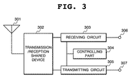
- Fig. 3 is a block diagram showing the configuration of a mobile station of the first embodiment.
- the mobile station of Fig. 3 comprises an antenna 301, a transmission/reception shared device 302, a receiving circuit 303, a controlling part 304, a transmitting circuit 305, a receiving circuit terminal 306, and a transmitting circuit terminal 307. Both the mobile station 21 and the mobile station 71 are configures as shown in Fig. 3.
- the mobile station receives the downlink signals transmitted by the base station in its receiving circuit 303, via the antenna 301 and the transmission/reception shared device 302.
- the receiving circuit 303 uses the sign for that channel to fetch and receive the signals of the set channel, among all the signals through the channels that have been multiplexed in the same carrier frequency being used and interference signals arriving from other base stations.
- Signals sent through a channel include user information mainly consisting of voice and data and control information used for changing carrier frequencies or signs.
- the receiving circuit 303 outputs user information to the receiving circuit terminal 306 and sends control information to the controlling part 304.
- the receiving circuit 303 measures the power within the frequency band of a carrier frequency being used for downlink. It also temporarily changes the frequency that it receives to measure the power within the frequency band of another carrier frequency. The receiving circuit 303 then sends the measurement of received power to the controlling part 304.
- the controlling part 304 Based on the control information sent from the receiving circuit 303, the controlling part 304 designates a carrier frequency and a channel sign to be set in the receiving circuit 303 and the transmitting circuit 305 by these circuits, respectively. Furthermore, based on the measurement of received power sent from the receiving circuit 303, the controlling part 304 generates information to notify the base station controller and sends it to the transmitting circuit 305. Based on the control information sent from the receiving circuit 303, the controlling part 304 updates the transmitting power and notifies the new value to the transmitting circuit 305.
- the transmitting circuit 305 generates signals to be transmitted, using the information sent from the controlling part 304 for notification to the base station controller and the user information, i.e., uplink signals, that has been sent from the transmitting circuit terminal 307. It then transmits these signals to the base station, via the transmission/reception shared device 302 and the antenna 301, at the level of transmitting power notified by the controlling part 304.
- Fig. 16 is a block diagram showing the configuration of a base station controller according to the first embodiment of the present invention.
- the base station controller of Fig. 16 comprises a controlling part 1601, a base station receiving part 1602, a base station transmitting part 1603, a communication network transmitting part 1604, a communication network receiving part 1605, a base station receiving terminal 1606, a base station transmitting terminal 1607, a communication network transmitting terminal 1608, and a communication network receiving terminal 1609.
- the base station controller 51 is configured as shown in Fig. 16.
- the base station receiving part 1602 receives control information from a base station and sends it to the controlling part 1601.
- the communication network receiving part 1605 receives control information from another base station controller and sends it to the controlling part 1601. Based on these sets of control information, the controlling part 1601 generates the control information to be notified to the base station and sends it to the base station transmitting part 1603. It also generates the control information to be notified to the other base station and sends it to the communication network transmitting part1604.
- the base station transmitting part 1603 in turn sends the control information sent from the controlling part 1601 to the base station.
- the communication network transmitting part 1604 sends the control information sent from the controlling part 1601 to the communication network.
- the mobile station 21 sets a base station 11 and two circuits; the downlink channel 31 is used for transmission from the base station 11 to the mobile station 21, and the uplink channel 41 is used for transmission from the mobile station 21 to the base station 11. Meanwhile, a mobile station 71 sets a channel 81 for downlink and a channel 91 for uplink between itself and a base station 61, and communicates with the base station 61.
- the base station 11 measures the ratio between the desired wave power and the interference wave power along the uplink channel 41 from the mobile station 21, and compares the measured ratio with a pre-determined target value. Base on the results of the comparison, the base station 11 directs the mobile station to increase or decrease its transmitting power so that the resulting ratio will be as close to the target value as possible. Using the similar approach, the base station 61 ensures that the ratio between the desired wave power and the interference wave power along the uplink channel 91 of the mobile station 21 will be as close to the target value as possible.
- the mobile station 21 measures the received power Qa of the downlink carrier frequency from a near-by base station belonging to Cellular System A. It also measures the received power Qb of the downlink carrier frequency from a base station belonging to Cellular System B.
- the base station controller 51 of Cellular System A acquires information on the mean frequency of downlink carrier frequencies Gb1 through Gb3 of Cellular System B, via the communication network to which the base station controller 101 of Cellular System B is connected. The base station controller 51 then informs the acquired information, using the base stations 11 through 13. From the information informed by the base stations 11 through 13, the mobile station 21 can identify the downlink carrier frequencies Gb1 through Gb3 of Cellular System B.
- the mobile station 21 usually receives signals continuously along the downlink channel. However, if the necessity arises to measure the received power of a different carrier frequency, the base station will increase temporarily the rate of transmitting information along the downlink channel so that the required amount of information can be sent in a shorter time. This will create a blank period, i.e., no transmission period, while ensuring that the average rate of transmitting information will be maintained at an appropriate level. Using this blank period thus created, the mobile station 21 will change the frequency to receive, and measure the received power of the carrier frequency being used by the base stations 61 through 63 of Cellular System B for transmission.
- the base station controller 51 determines a carrier frequency to use when setting a channel between the base station 11 and the mobile station 21. If it uses Fa1 or Fa2 as uplink carrier frequency and Ga1 or Ga2 as downlink carrier frequency, adjacent carrier frequency interference with Cellular System B is unlikely to be a serious problem. Therefore, the present embodiment addresses cases where the base station 11 and the mobile station 21 start communication by using Fa3 as uplink carrier frequency and Ga3 as downlink carrier frequency. Between the base station 61 and the mobile station 71 of Cellular System B, it will be assumed that Fb1 is used as uplink carrier frequency and Gb1 as downlink carrier frequency.
- the base station controller 51 has informed the mean frequency of downlink carrier frequencies Gb1, Gb2, and Gb3 of Cellular System B, using the common control channel shared by the base stations 11, 12, and 13. Before the start of communication, the mobile station 21 receives the information thus informed from the base station 11.
- the base station controller 51 assigns to the mobile station 21 a carrier frequency that is not adjacent to the carrier frequencies of Cellular System B, based on the measurement information on the received power Qa and/or Qb sent from the mobile station 21. More specifically, there are two approaches to this assignment. One approach assigns a carrier frequency that is not adjacent to the carrier frequencies of Cellular System B if the received power Qb is higher than the pre-determined threshold. The other approach assigns a carrier frequency that is not adjacent to the carrier frequencies of Cellular System B if the difference between the received power Qb and the received Power Qa is greater than the pre-determined threshold.
- the present embodiment employs the second approach. That is, if the difference between the received power Qb and the received Power Qa is greater than the pre-determined threshold while Cellular System A is using a carrier frequency that is adjacent to the carrier frequencies of Cellular System B, then the present embodiment determines that the carrier frequency must be changed in order to avoid adjacent frequency interference and assigns a carrier frequency that is not adjacent to the carrier frequencies of Cellular System B.
- the base station controller 51 assigns a carrier frequency to the mobile station 21, based on the measurement information on the received power Qa and/or Qb sent from the mobile station 21, as stated above.
- the mobile station 21, therefore, needs to inform the measurement information it has obtained to the base station controller 51.
- the mobile station 21 informs the measurements of the received power Qa and/or the received power Qb.
- Another approach relates to cases where the carrier frequency is changed on condition that the difference between the received power Qb and the received power Qa is greater than the pre-determined threshold; in such cases, the information to be sent by the mobile station 21 should contain the difference between the received power Qb and the received power Qa.
- Yet another approach relates to cases where the mobile station 21 determines that the condition for changing the carrier frequency in order to avoid adjacent channel interference is satisfied; in such cases, the information to be sent by the mobile station 21 should contain the results of this determination.
- the present embodiment employs the last approach, in which the mobile station 21 informs that the condition for changing the carrier frequency has been satisfied.
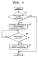
- Fig. 4 is a flow chart showing the operation of the base station controller 51 when performing control for avoiding interference.
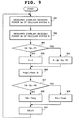
- Fig. 5 is a flow chart showing the operation of the mobile station 21 when performing interference avoidance control.
- the descriptions of all the embodiments below represent the values of transmitting power and received power in decibels. Also note that, in all the embodiments below, communication between the base station controller 51 and the mobile station 21 is conducted via the base station 11.
- the base station controller 51 After determining the carrier frequency to be used by the mobile station 21 and starting communication, the base station controller 51 checks whether the carrier frequency is adjacent to the carrier frequencies of Cellular System B or not (Step 401). If not, it terminates without performing interference avoidance control.
- the base station controller 51 notifies the mobile station 21 that interference avoidance control has been activated (Step 402). Along with this information, the base station controller 51 notifies the thresholds R1 and R2 to be used by the mobile station for interference avoidance control, and the measuring cycles Tshort and Tlong.
- the mobile station 21 When it starts interference avoidance control and determines that the carrier frequency must be changed for avoiding interference, the mobile station 21 notifies the base station controller 51 of the fact. Receiving this notification (Step 403), the base station controller 51 begins the process of changing the carrier frequency (Step 404). It selects either Fa1 or Fa2 as uplink carrier frequency and either Ga1 or Ga2 as downlink carrier frequency, which are not adjacent to the carrier frequencies of Cellular System B. The base station controller 51 then changes the carrier frequency to the selected carrier frequency.
- the controlling part 304 of the mobile station 21 Upon receiving a notification of the activation of interference avoidance control from the base station controller 51, the controlling part 304 of the mobile station 21 begins the process of interference avoidance control, as described below.
- the mobile station 21 uses the receiving circuit 303 to measure the downlink received power Qa of Cellular System A (Step 501).
- the mobile station 21 is using the carrier frequency Ga3 for downlink, so it measures the power within that frequency band.
- the mobile station 21 also uses the receiving circuit 303 to measure the downlink received power Qb of Cellular System B (Step 502).
- the mobile station 21 Since it has information concerning the mean frequency of the downlink carrier frequency Gb1 of Cellular System B, the mobile station 21 changes temporarily the frequency that it receives in order to measure the power within the frequency band associated with the carrier frequency Gb1. If, in Step 503, it finds that the difference between the received power Qb and the received power Qa is greater than the pre-determined threshold R1, the mobile station 21 determines that the carrier frequency must be changed. It then generates control information to notify that the condition for changing the carrier frequency has been satisfied, and transmits the control information to the base station 11, using the transmitting circuit 305. The base station 11 in turn notifies the same control information to the base station controller 51 (Step 504).
- Step 503 it finds that the difference between the received power Qb and the received power Qa is equal to or smaller than the pre-determined threshold R1
- the mobile station 21 proceeds to Step 505. If it finds that the difference between the received power Qb and the received power Qa is greater than the pre-determined threshold R2, the mobile station 21 sets Tint, the measuring cycle for the received power Qa and Qb, to Tshort, the short measuring cycle (Step 506). Otherwise it sets Tint, the measuring cycle, to Tlong, the measuring cycle longer than Tshort (Step 507). After the elapse of the delay time for the measuring cycle Tint (Step 508), the mobile station 21 repeats the same procedure, beginning with Step 501.
- the threshold R1 to be used in the process of interference avoidance control described above should be equal to a value obtained by subtracting a pre-determined margin from the difference between the transmitting power within the frequency band of the carrier frequency set for use by the mobile station 21 for transmission and the portion of such transmitting power that leaks into the frequency band of the adjacent carrier frequency.
- the value of the threshold R2 should be smaller than R1.
- a longer measuring cycle, Tlong is used when the difference between the received power Qb and the received power Qa is equal to or smaller than the threshold R2.
- the measuring frequency is lower in comparison to when the shorter measuring cycle, Tshort, is used throughout the process.
- the difference between the received power Qb and the received power Qa is even smaller than the threshold R2, which is set to a smaller value than the threshold R1. This further means that the probability that the difference between the received power Qb and the received power Qa exceeds the threshold R1 can be maintained at a low level, even if the mobile station moves while the measuring cycle Tlong is being used.
- the measuring cycle is set to a shorter value, Tshort, when the difference between the received power Qb and the received power Qa is greater than the threshold R2.
- Tshort a shorter value
- the probability that the difference between the received power Qb and the received power Qa exceeds the threshold R1 can also be maintained at a low level while this measuring cycle is being used.
- the present embodiment can lower the average measuring frequency, while reducing the probability that the difference between the received power Qb and the received power Qa may exceed the threshold R1.
- the adjacent carrier frequency interference avoiding method for cellular system of the second embodiment cellular systems is configured as shown in Fig. 1.
- This embodiment is applied to cellular systems using THE CDMA (Code Division Multiple Access) for radio access technology.
- Fig. 2 shows the arrangement of carrier frequencies on the frequency axis.
- the arrangement of carrier frequencies assigned to each cellular system is also the same as the first embodiment.
- the mobile station of the second embodiment is configured as shown in Fig. 3, similarly to the first embodiment. Its operation is the same as the mobile station of the first embodiment, except for the controlling part 304.
- the base station controller of the second embodiment is configured as shown in Fig. 16, also similarly to the first embodiment. Its operation is the same as the base station controller of the first embodiment, except for the controlling part 1601.
- the mobile station 21 measures the received power Qa of the downlink carrier frequency from a near-by base station belonging to Cellular System A. It also measures the received power Qb of the downlink carrier frequency from a base station belonging to Cellular System B.
- the base station 11 and the mobile station 21 start communication by using Fa3 as uplink carrier frequency and Ga3 as downlink carrier frequency.
- Fa3 uplink carrier frequency
- Ga3 downlink carrier frequency.
- Fb1 is used as uplink carrier frequency
- Gb1 downlink carrier frequency.
- the second embodiment employs the following frequency assignment method for Cellular System A. That is, if the difference between the received power Qb and the received Power Qa is greater than the pre-determined threshold while Cellular System A is using a carrier frequency that is adjacent to the carrier frequencies of Cellular System B, then the second embodiment determines that the carrier frequency must be changed in order to avoid adjacent frequency interference and assigns a carrier frequency that is not adjacent to the carrier frequencies of Cellular System B.
- the base station controller 51 uses the measurement information on the received power Qa and/or Qb sent from the mobile station 21 to assign a carrier frequency to the mobile station 21.
- the second embodiment employs the approach in which the mobile station 21 informs the measurements of the received power Qa and/or the received power Qb.
- Fig. 6 is a flow chart showing the operation of the base station controller 51 when performing control for avoiding interference.
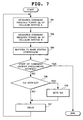
- Fig. 7 is a flow chart showing the operation of the mobile station 21 when performing control for avoiding interference.
- the base station controller 51 After determining the carrier frequency to be used by the mobile station 21 and starting communication, the base station controller 51 checks whether the carrier frequency is adjacent to the carrier frequencies of Cellular System B or not (Step 601). If not, it terminates without performing interference avoidance control.
- the base station controller 51 sets Tint, the cycle for measuring the received power of the carrier frequency of the downlink from the mobile station for interference avoidance control, to Tshort, the short measuring cycle (Step 602).
- the base station controller 51 then notifies the mobile station 21 that interference avoidance control has been activated, together with the information on the measuring cycle Tint (Step 603).
- the mobile station 21 After it starts interference avoidance control, the mobile station 21 measures the downlink received power Qa of Cellular System A and the downlink received power Qb of Cellular System B, and notifies the resulting measurements to the base station controller 51. Upon receiving the notification (Step 604), the base station controller 51 proceeds to Step 605.
- Step 605 it finds that the difference between the received power Qb and the received power Qa is greater than the pre-determined threshold R1
- the base station controller 51 determines that the carrier frequency must be changed, and begins the process of changing the carrier frequency (Step 606). It selects either Fa1 or Fa2 as uplink carrier frequency and either Ga1 or Ga2 as downlink carrier frequency, which are not adjacent to the carrier frequencies of Cellular System B. The base station controller 51 then notifies the selection to the mobile station 21, which will change the carrier frequency to the selected carrier frequency.
- Step 605 it finds that the difference between the received power Qb and the received power Qa is equal to or smaller than the pre-determined threshold R1
- the base station controller 51 proceeds to Step 607. If it finds that the difference between the received power Qb and the received power Qa is greater than the pre-determined threshold R2, the base station controller 51 sets Tint, the measuring cycle for the received power Qa and Qb, to Tshort, the short measuring cycle (Step 608). Otherwise it sets the measuring cycle Tint to Tlong, the measuring cycle longer than Tshort (Step 609).
- Step 608 or 609 the base station controller 51 notifies the new control cycle Tint to the mobile station 21 (Step 611), and repeats the procedure from Step 604. Otherwise, it repeats the procedure from Step 604 without notifying the control cycle Tint.
- the thresholds R1 and R2 for use in the process of interference avoidance control described above are set in a manner similar to the first embodiment.
- the mobile station 21 Upon receiving a notification of the activation of interference avoidance control from the base station controller 51, the mobile station 21 sets the measuring cycle Tint to the value designated in the notification.
- the controlling part 304 of the mobile station 21 begins the process of interference avoidance control, as described below.
- the mobile station 21 uses the receiving circuit 303 to measure the received power Qa of the carrier frequency Ga3 of Cellular System A (Step 701).
- the mobile station 21 also uses the receiving circuit 303 to measure the received power Qb of the carrier frequency Gb1 of Cellular System B (Step 702). It then generates control information to notify the measurements of the received power Qa and Qb, and uses the transmitting circuit 305 to transmit the control information to the base station 11.
- the base station 11 in turn notifies the same control information to the base station controller 51 (Step 703). If a notification to start the process of changing the carrier frequency is received from the base station controller 51 in Step 704, the mobile station 21 begins controlling the process of changing the carrier frequency.
- the mobile station 21 further checks for a notification of the control cycle Tint (Step 705). If there is one, it sets the control cycle Tint to the value designated in the notification (Step 706). After the elapse of the delay time for the control cycle Tint (Step 707), the mobile station 21 repeats the same procedure, beginning with Step 701.
- a longer measuring cycle, Tlong is used when the difference between the received power Qb and the received power Qa is equal to or smaller than the threshold R2.
- Tlong a longer measuring cycle
- the adjacent carrier frequency interference avoiding method for cellular system of the third embodiment is configured as shown in Fig. 1.
- This embodiment is applied to cellular systems using the CDMA (Code Division Multiple Access) for radio access technology.
- Fig. 2 shows the arrangement of carrier frequencies on the frequency axis.
- the arrangement of carrier frequencies assigned to each cellular system is also the same as the first embodiment.
- the mobile station of the third embodiment is configured as shown in Fig. 3, similarly to the first embodiment. Its operation is the same as the mobile station of the first embodiment, except for the controlling part 304.
- the base station controller of the third embodiment is configured as shown in Fig. 16, also similarly to the first embodiment. Its operation is the same as the base station controller of the first embodiment, except for the controlling part 1601.
- the mobile station 21 measures the received power Qa of the downlink carrier frequency from a near-by base station belonging to Cellular System A. It also measures the received power Qb of the downlink carrier frequency from a base station belonging to Cellular System B.
- the base station 11 and the mobile station 21 start communication by using Fa3 as uplink carrier frequency and Ga3 as downlink carrier frequency.
- Fa3 uplink carrier frequency
- Ga3 downlink carrier frequency.
- Fb1 is used as uplink carrier frequency
- Gb1 downlink carrier frequency.
- the base station controller 51 changes the level of the maximum transmitting power of the mobile station 21, based on the measurement information on the received power Qa and/or Qb sent from the mobile station 21.
- the base station controller 51 pre-determines the upper limit of the transmitting power of a mobile station. If the receiving power Qb exceeds a pre-determined threshold, the base station controller 51 sets the maximum transmitting power to a value obtained by subtracting the surplus from the upper limit of the transmitting power. In another approach, if the difference between the received power Qb and the received power Qa exceeds a pre-determined threshold, the base station controller 51 sets the maximum transmitting power to a value obtained by subtracting the surplus from the upper limit of the transmitting power.
- the third embodiment employs the second approach. That is, if the difference between the received power Qb and the received Power Qa is greater than the pre-determined threshold while Cellular System A is using a carrier frequency adjacent to the carrier frequencies of Cellular System B, then the maximum transmitting power of the mobile station is decreased in order to avoid adjacent frequency interference.
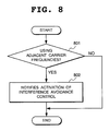
- Fig. 8 is a flow chart showing the operation of the base station controller 51 when performing control for avoiding interference.
- Fig. 9 is a flow chart showing the operation of the mobile station 21 when performing control for avoiding interference.
- the base station controller 51 After determining the carrier frequency to be used by the mobile station 21 and starting communication, the base station controller 51 checks whether the carrier frequency is adjacent to the carrier frequencies of Cellular System B or not (Step 801). If not, it terminates without performing interference avoidance control.
- the base station controller 51 notifies the mobile station 21 that interference avoidance control has been activated (Step 802). Along with this information, the base station controller 51 notifies the thresholds R1 and R2 as well as measurement cycle Tshort and Tlong to be used by the mobile station for interference avoidance control. It also notifies the upper limit of transmitting power Plimit and the lower limit of the maximum transmitting power.
- the controlling part 304 of the mobile station 21 begins the process of interference avoidance control, as described below.
- the mobile station 21 uses the receiving circuit 303 to measure the received power Qa of the carrier frequency Ga3 of Cellular System A (Step 901).
- the mobile station 21 also uses the receiving circuit 303 to measure the received power Qb of the carrier frequency Gb1 of Cellular System B (Step 902).
- Step 903 if it finds that the difference between the received power Qb and the received power Qa is greater than the pre-determined threshold R1, the mobile station 21 calculates the surplus S (Step 904). Otherwise, the mobile station 21 sets the surplus S to 0 (Step 905). It then sets the maximum transmitting power Pmax to a value equaling the upper limit of transmitting power Plimit, less the surplus S (Step 906).
- the controlling part 304 of the mobile station 21 sets the transmitting power from the transmitting circuit 305 so that it will not exceed the maximum transmitting power Pmax.
- Step 907 it finds that the difference between the received power Qb and the received power Qa is greater than the pre-determined threshold R2
- the mobile station 21 sets Tint, the measuring cycle for the received power Qa and Qb, to Tshort, the short measuring cycle (Step 908). Otherwise it sets the measuring cycle Tint to Tlong, the measuring cycle longer than Tshort (Step 909). After the elapse of the delay time for the measuring cycle Tint (Step 910), the mobile station 21 repeats the same procedure, beginning with Step 901.
- the thresholds R1 and R2 for use in the process of interference avoidance control described above are set in a manner similar to the first embodiment.
- a longer measuring cycle, Tlong is used when the difference between the received power Qb and the received power Qa is equal to or smaller than the threshold R2.
- Tlong a longer measuring cycle
- the maximum transmitting power of a mobile station and the measuring cycle Tint are updated by the mobile station on an autonomous basis.
- the adjacent carrier frequency interference avoiding method for cellular system of the fourth embodiment is the same as the method of the third embodiment, except that the base station controller 51 performs the updating process for these values.
- the mobile station of the fourth embodiment also operates similarly to that of the third embodiment, except for the controlling part 304 of the mobile station 21, which handles the differing portion of the procedure.
- the base station controller 51 When updating the maximum transmitting power and the measuring cycle Tint, the base station controller 51 relies on the measurement information on the received power Qa and/or Qb sent from the mobile station 21. The mobile station 21, therefore, must inform the measurement information it has obtained to the base station controller 51. In one approach, the mobile station 21 informs the measurements of the received power Qa and/or the received power Qb. In another approach, the mobile station 21 informs the difference between the received power Qb and the received power Qa.
- the fourth embodiment employs the first approach, in which the measurements of both the received power Qb and the received power Qa are notified.
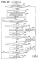
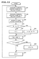
- Fig. 10 is a flow chart showing the operation of the base station controller 51 when performing interference avoidance control.
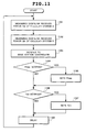
- Fig. 11 is a flow chart showing the operation of the mobile station 21 when performing interference avoidance control.
- the base station controller 51 After determining the carrier frequency to be used by the mobile station 21 and starting communication, the base station controller 51 checks whether the carrier frequency is adjacent to the carrier frequencies of Cellular System B or not (Step 1001). If not, it terminates without performing interference avoidance control.
- the base station controller 51 sets Tint, the cycle for measuring the received power of the carrier frequency in the downlink from the mobile station for interference avoidance control, to Tshort, the short measuring cycle (Step 1002).
- the base station controller 51 then notifies the mobile station 21 that interference avoidance control has been activated, together with the information on the measuring cycle Tint (Step 1003).
- the mobile station 21 After it starts interference avoidance control, the mobile station 21 measures the downlink received power Qa of Cellular System A and the downlink received power Qb of Cellular System B, and notifies the resulting measurements to the base station controller 51. Upon receiving the notification (Step 1004), the base station controller 51 proceeds to Step 1005. In Step 1005, if it finds that the difference between the received power Qb and the received power Qa is greater than the pre-determined threshold R1, the mobile station 21 calculates the surplus S (Step 1006). Otherwise, the mobile station 21 sets the surplus S to 0 (Step 1007).
- Step 1008 sets the maximum transmitting power Pmax to a value equaling the upper limit of transmitting power Plimit, less the surplus S. If the maximum transmitting power Pmax has been changed in Step 1007 or 1008, the base station controller 51 notifies the new maximum transmitting power Pmax to the mobile station 21 (Step 1010).
- the base station controller 51 sets Tint, the measuring cycle for the received power Qa and Qb, to Tshort, the short measuring cycle (Step 1012). Otherwise it sets the measuring cycle Tint to Tlong, the measuring cycle longer than Tshort (Step 1013). If the control cycle Tint has been changed in Step 1012 or 1013, the base station controller 51 notifies the new control cycle Tint to the mobile station 21 (Step 1015), and repeats the procedure from Step 1004. Otherwise, it repeats the procedure from Step 1004, without notifying the control cycle Tint.
- the thresholds R1 and R2 for use in the process of interference avoidance control described above are set in a manner similar to the third embodiment.
- the controlling part 304 of the mobile station 21 begins the process of interference avoidance control, as described below.
- the mobile station 21 uses the receiving circuit 303 to measure the received power Qa of the carrier frequency Ga3 of Cellular System A (Step 1101).
- the mobile station 21 also uses the receiving circuit 303 to. measure the received power Qb of the carrier frequency Gb1 of Cellular System B (Step 1102).
- Step 1103 the mobile station 21 checks for a notification of the maximum transmitting power Pmax from the base station controller 51 (Step 1104). If there is one, it sets the maximum transmitting power Pmax to the value designated in the notification (Step 1105).
- the controlling part 304 of the mobile station 21 sets the transmitting power from the transmitting circuit 305 so that it will not exceed the maximum transmitting power Pmax.
- the mobile station 21 further checks for a notification of the control cycle Tint (Step 1106). If there is one, it sets the control cycle Tint to the value designated in the notification (Step 1107). After the elapse of the delay time for the control cycle Tint (Step 1108), the mobile station 21 repeats the same procedure, beginning with Step 1101.
- a longer measuring cycle, Tlong is used when the difference between the received power Qb and the received power Qa is equal to or smaller than the threshold R2.
- Tlong a longer measuring cycle
- both the maximum transmitting power of a mobile station and the measuring cycle Tint are determined by the mobile station on an autonomous basis.
- the maximum transmitting power of a mobile station is determined by the mobile station, but the measuring cycle Tint is determined by the base station controller 51.
- the rest of the fifth method is the same as the method of the third embodiment.
- the mobile station of the fifth embodiment also operates similarly to that of the third embodiment, except for the controlling part 304, which handles the differing portion of the procedure.
- the base station controller 51 When updating the maximum transmitting power and the measuring cycle Tint, the base station controller 51 relies on the measurement information on the received power Qa and/or Qb sent from the mobile station 21. The mobile station 21, therefore, must inform the measurement information it has obtained to the base station controller 51. In one approach, the mobile station 21 informs the measurements of the received power Qa and/or the received power Qb. In another approach, the mobile station 21 informs the difference between the received power Qb and the received power Qa.
- the fifth embodiment employs the first approach, in which the measurements of both the received power Qb and the received power Qa are notified.
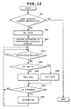
- Fig. 12 is a flow chart showing the operation of the base station controller 51 when performing interference avoidance control.
- Fig. 13 is a flow chart showing the operation of the mobile station 21 when performing interference avoidance control.
- the base station controller 51 After determining the carrier frequency to be used by the mobile station 21 and starting communication, the base station controller 51 checks whether the carrier frequency is adjacent to the carrier frequencies of Cellular System B or not (Step 1201). If not, it terminates without performing interference avoidance control.
- the base station controller 51 sets Tint, the cycle for measuring the received power of the carrier frequency of the downlink from the mobile station for interference avoidance control, to Tshort, the short measuring cycle (Step 1202).
- the base station controller 51 then notifies the mobile station 21 that interference avoidance control has been activated (Step 1203).
- the base station controller 51 notifies the measuring cycle Tint, the threshold R1 for use by the mobile station for interference avoidance control, the upper limit of the maximum transmitting power Plimit, and the lower limit of the maximum transmitting power.
- the mobile station 21 After it starts interference avoidance control, the mobile station 21 measures the downlink received power Qa of Cellular System A and the downlink received power Qb of Cellular System B, and notifies the resulting measurements to the the base station controller 51. Upon receiving the notification (Step 1204), the base station controller 51 proceeds to Step 1205. If, in Step 1205, it finds that the difference between the received power Qb and the received power Qa is greater than the pre-determined threshold R2, the base station controller 51 sets Tint, the measuring cycle for the received power Qa and Qb, to Tshort, the short measuring cycle (Step 1206). Otherwise it sets the measuring cycle Tint to Tlong, the measuring cycle longer than Tshort (Step 1207).
- Step 1206 If the control cycle Tint has been changed in Step 1206 or 1207, the base station controller 51 notifies the new control cycle Tint to the mobile station 21 (Step 1209), and repeats the procedure from Step 1204. Otherwise, it repeats the procedure from Step 1204 without notifying the control cycle Tint.
- the controlling part 304 of the mobile station 21 Upon receiving a notification of the activation of interference avoidance control from the base station controller 51, the controlling part 304 of the mobile station 21 begins the process of interference avoidance control, as described below.
- the mobile station 21 uses the receiving circuit 303 to measure the received power Qa of the carrier frequency Ga3 of Cellular System A (Step 1301).
- the mobile station 21 also uses the receiving circuit 303 to measure the received power Qb of the carrier frequency Gb1 of Cellular System B (Step 1302).
- Step 1303 It then generates control information to notify the measurements of the received power Qa and Qb, and uses the transmitting circuit 305 to transmit the control information to the base station 11.
- the base station 11 in turn notifies the same control information to the base station controller 51 (Step 1303).
- Step 1304 if it finds that the difference between the received power Qb and the received power Qa is greater than the pre-determined threshold R1, the mobile station 21 calculates the surplus S (Step 1305). Otherwise, the mobile station 21 sets the surplus S to 0 (Step 1306).
- the controlling part 304 of the mobile station 21 sets the transmitting power from the transmitting circuit 305 so that it will not exceed the maximum transmitting power Pmax.
- the mobile station 21 further checks for a notification of the control cycle Tint (Step 1308). If there is one, it sets the control cycle Tint to the value designated in the notification (Step 1309). After the elapse of the delay time for the control cycle Tint (Step 1310), the mobile station 21 repeats the same procedure, beginning with Step 1301.
- the thresholds R1 and R2 for use in the process of interference avoidance control described above are set in a manner similar to the third embodiment.
- a longer measuring cycle, Tlong is used when the difference between the received power Qb and the received power Qa is equal to or smaller than the threshold R2.
- Tlong a longer measuring cycle
- both the maximum transmitting power of a mobile station and the measuring cycle Tint are determined by the mobile station on an autonomous basis.
- the measuring cycle Tint is determined by the mobile station, but the maximum transmitting power of a mobile station is determined by the base station controller 51.
- the rest of the sixth method is the same as the method of the third embodiment.
- the mobile station of the sixth embodiment also operates similarly to that of the third embodiment, except for the controlling part 304 of the mobile station 21, which handles the differing portion of the procedure.
- the base station controller 51 relies on the measurement information on the received power Qa and/or Qb sent from the mobile station 21 to update the maximum transmitting power.
- the mobile station 21 informs the measurements of the received power Qa and/or the received power Qb.
- the mobile station 21 informs the difference between the received power Qb and the received power Qa.
- the fifth embodiment employs the first approach, in which the measurements of both the received power Qb and the received power Qa are notified.
- Fig. 14 is a flow chart showing the operation of the base station controller 51 when performing interference avoidance control.
- Fig. 15 is a flow chart showing the operation of the mobile station 21 when performing interference avoidance control.
- the base station controller 51 After determining the carrier frequency to be used by the mobile station 21 and starting communication, the base station controller 51 checks whether the carrier frequency is adjacent to the carrier frequencies of Cellular System B or not (Step 1401). If not, it terminates without performing interference avoidance control.
- the base station controller 51 notifies the mobile station 21 that interference avoidance control has been activated (Step 1402). Along with this information, the base station controller 51 notifies the thresholds R2 for use by the mobile station for interference avoidance control, and the measuring cycles Tshort and Tlong.
- the mobile station 21 After it starts interference avoidance control, the mobile station 21 measures the downlink received power Qa of Cellular System A and the downlink received power Qb of Cellular System B, and notifies the resulting measurements to the base station controller 51. Upon receiving the notification (Step 1403), the base station controller 51 proceeds to Step 1404. In Step 1404, if it finds that the difference between the received power Qb and the received power Qa is greater than the pre-determined threshold R1, the mobile station 21 calculates the surplus S (Step 1405). Otherwise, the mobile station 21 sets the surplus S to 0 (Step 1406).
- Step 1407 sets the maximum transmitting power Pmax to a value equaling the upper limit of transmitting power Plimit, less the surplus S. If the maximum transmitting power Pmax has been changed in Step 1405 or 1406, the base station controller 51 notifies the new maximum transmitting power Pmax to the mobile station 21 (Step 1409), and repeats the procedure from Step 1403. Otherwise, it repeats the procedure from Step 1403, without notifying the maximum transmitting power Pmax.
- the controlling part 304 of the mobile station 21 begins the process of interference avoidance control, as described below.
- the mobile station 21 uses the receiving circuit 303 to measure the received power Qa of the carrier frequency Ga3 of Cellular System A (Step 1501).
- the mobile station 21 also uses the receiving circuit 303 to measure the received power Qb of the carrier frequency Gb1 of Cellular System B (Step 1502). It then generates control information to notify the measurements of the received power Qa and Qb, and uses the transmitting circuit 305 to transmit the control information to the base station 11.
- the base station 11 in turn notifies the same control information to the base station controller 51 (Step 1503).
- the mobile station 21 checks for a notification of the maximum transmitting power Pmax (Step 1504). If there is one, it sets the maximum transmitting power Pmax to the value designated in the notification (Step 1505).
- the controlling part 304 of the mobile station 21 sets the transmitting power from the transmitting circuit 305 so that it will not exceed the maximum transmitting power Pmax. If, in Step 1506, it finds that the difference between the received power Qb and the received power Qa is greater than the pre-determined threshold R2, the mobile station 21 sets Tint, the measuring cycle for the received power Qa and Qb, to Tshort, the short measuring cycle (Step 1507). Otherwise it sets the measuring cycle Tint to Tlong, the measuring cycle longer than Tshort (Step 1508). After the elapse of the delay time for the measuring cycle Tint (Step 1509), the mobile station 21 repeats the same procedure, beginning with Step 1501.
- the thresholds R1 and R2 for use in the process of interference avoidance control described above are set in a manner similar to the third embodiment.
- a longer measuring cycle, Tlong is used when the difference between the received power Qb and the received power Qa is equal to or smaller than the threshold R2.
- Tlong a longer measuring cycle
- Cellular System A and Cellular System B have multiple base stations connected to one base station controller, respectively. It should be noted, however, each of the base stations may be provided with one base station controller. In this case, a base station controller may be configured in a base station as an integral part of the base station.
- the information used by a mobile station for interference avoidance control i.e., the thresholds R1 and R2, the measuring cycles Tshort and Tlong, and the upper and lower limits of the transmitting power from the mobile station, are notified separately by the base station controller to the mobile station at the beginning of interference avoidance control.
- a base station may inform all or part of these pieces of information, using a common control channel for shared use by all mobile stations, for each mobile station to receive and set in advance.
- the present invention it is possible to reduce the frequency of measurements of the received power of a carrier frequency, which must be conducted by a mobile station in reducing interference between adjacent carrier frequencies, for use when changing the carrier frequency or changing the maximum transmitting power from the mobile station, depending on the resulting measurements.
- the frequency of increasing the transmitting power from a base station for increased information transmission rate can be reduced, which is important for mobile stations of a type that can receive only one carrier frequency
- the present invention can provide the effect of preventing an increase in interference of downlink with other channels and consequently of saving link capacity. Furthermore, in cases where fast closed-loop transmitter power control, which updates the transmitting power from a mobile station through control signals sent from a base station in very short cycles, is conducted, the frequency of interrupting such control can be reduced. This further provides the effect of reducing the possibilities that communication quality may be deteriorated due to a shortage of signal power in uplink channels and that interference may be increased due to excessive signal power in channels, which in turn produces the effect of further saving link capacity. Finally, the reduced measuring frequency contributes to a reduction in total power consumption of a mobile station during measurement.
Abstract
Description
- The present invention relates to an adjacent carrier frequency interference avoiding method for cellular system and a mobile station. In particular, the present invention relates to an adjacent carrier frequency interference avoiding method for cellular system, by which the occurrence of interference between different sets of signals sent using adjacent carrier frequencies can be avoided, when carrier frequencies used by two separate cellular systems are adjacent to each other on the frequency axis, as well as a mobile station and a base station controller that are used therein
- A cellular system is generally assigned a specific frequency band, in which multiple different carrier frequencies are set. A mobile station sets a link between itself and a base station that has been set within a service area and communicates with the base station bi-directionally. A transmitter of a base station and that of a mobile station are designed so that, when a base station transmits signals to a mobile station using a certain carrier frequency, or vice versa, power leakage into the frequency band of another carrier frequency that is adjacent on the frequency axis to the carrier frequency used by the transmitter will be minimized. It is impossible, however, for the transmitter to eliminate such power leakage completely, resulting in interference wave power given to signals of an adjacent carrier frequency at a certain ratio.
- Each of the mobile stations in one cellular system sets a link between itself and the nearest base station. In uplink, transmitting power from the mobile station is controlled so that the difference among the levels of reception power that the base station receives from multiple mobile stations will not be excessively large. Therefore, the power of interference between adjacent carrier frequencies that is received from signals of an adjacent carrier frequency sent from a mobile station is lower than desired wave power when it reaches the base station.
- In downlink, if the level of transmitting power from base station is constant, the interference wave power from signals of a frequency that is adjacent to desired wave signals reaches the mobile station along the same propagation path as desired wave signals. During the travel, the interference wave power attenuates along with desired waves do, and thus the power of interference between adjacent carrier frequencies becomes lower than desired wave power. Therefore, such interference between adjacent carrier frequencies is not a serious problem in one cellular system.
- On the other hand, interference between adjacent carrier frequencies may become a serious problem when two cellular systems are in the same service area. More specifically, a serious problem may occur if the first cellular system is assigned a frequency band adjacent to a frequency band of the second cellular system, and the first cellular sets a base station within this service area and communicates with a mobile station of the first cellular system.
- This situation will be described using Fig. 1 as one example. As shown in Fig. 1, there are two cellular systems: Cellular Systems A and B. Cellular System A consists of
base stations 11 through 13 and amobile station 21; Cellular System B consists ofbase stations 61 through 63 and amobile station 71. As shown in Fig. 2, Cellular System A is assigned carrier frequencies Fa1, Fa2, and Fa3 for uplink, and carrier frequencies Ga1, Ga2, and Ga3 for downlink; Cellular System B is assigned carrier frequencies Fb1, Fb2, and Fb3 for uplink and carrier frequencies Gb1, Gb2, and Gb3 for downlink. Carrier frequencies Fa3 and Ga3 of Cellular System A are adjacent to carrier frequencies Fb1 and Gb1 of Cellular System B, respectively, on the frequency axis. Themobile station 21 of Cellular System A is communicating using Fb3 for uplink and Gb3 for downlink; themobile station 71 of Cellular System B is communicating using Fb1 for uplink, and Gb1 for downlink. - When the
mobile station 21 approaches thebase station 61, uplink signals of themobile station 21 will be controlled by thebase station 11 to maintain received power at a desired level. At the same time, power received by thebase station 61 will grow sharply, and consequently power leakage into the carrier frequency Fb1, which is adjacent to the carrier frequency Fa3, will also become extremely high. This interference between the adjacent carrier frequencies will deteriorate the communication quality of uplink from themobile station 71 to thebase station 61. Similar deterioration in communication quality will take place along the downlink from themobile station 21, because of an increase in adjacent carrier frequency interference from the carrier frequency Gb1, which is transmitted by thebase station 61, to the carrier frequency Ga3. - One method to solve this problem is disclosed in Japanese Patent Laying-Open No. 11-341555. According to this method applied to the examples of Figs. 1 and 2, the
mobile station 21 of Cellular System A will measure the received power Qb of the carrier frequency transmitted from thebase station 61 of another cellular system, i.e., Cellular System B. Higher received power Qb means that thebase station 61 is nearer. Therefore, if the received power Qb is equal to or lower than a pre-determined threshold, any of the carrier frequencies will be used. - If the received power Qb is higher than the pre-determined threshold, carrier frequencies Fa1 or Fa2 for uplink and carrier frequencies Ga1 or Ga2 for downlink will be used since they are not adjacent to the carrier frequencies of Cellular System B. If Fa3 or Ga3, which is adjacent to the carrier frequencies of Cellular System B, is being used, the carrier frequency will be switched to any of the other carrier frequencies.
- When the
mobile station 21 controls its transmitting power so that the received power of uplink signals at thebase station 11 will be constant, received power, transmitting power, and power of adjacent carrier frequency interference will be in the following relationship. The smaller the received power Qa of the carrier frequency transmitted by thebase station 11 of Cellular System A is, the higher the transmitting power from themobile station 21 becomes. This in turn makes the power of interference between the adjacent carrier frequencies affecting thebase station 61 greater. Therefore, another possible method is to have themobile station 21 measure the received power Qa in addition to the received power Qb, and prevent the carrier frequencies Fa3 or Ga3 from being used if the difference between received power Qb and Qa is greater than the pre-determined threshold. - These methods can reduce interference between adjacent carrier frequencies, because they use carrier frequencies other than Fa3 and Ga3 when the
mobile station 21 is likely to cause strong adjacent carrier frequency interference in the uplink from thebase station 61 or when the downlink from themobile station 21 may receive strong adjacent carrier frequency interference from thebase station 61. - According to yet another method disclosed in Japanese Patent Laying-Open No. 11-341555, when the
mobile station 21 is using Fa3 for uplink, it measures the received power Qb of the carrier frequency transmitted by thebase station 61. If the received power Qb is higher than the pre-determined threshold, themobile station 21 sets the maximum transmitting power for uplink to a value that is lower than the usual maximum value by a difference between the received power Qb and the pre-determined threshold. Another possible method is to have themobile station 21 additionally measure the received power Qa of the carrier frequency transmitted by thebase station 11, and reduce the setting of maximum transmitting power by a difference between the received power Qb and Qa. - These methods can reduce interference between adjacent carrier frequencies, because they reduce the maximum value of transmitting power of the
mobile station 21 if the station is using Fa3 for uplink and thus is likely to cause strong adjacent carrier frequency interference in the uplink from thebase station 61. These methods are effective when there are no other carrier frequencies available. In addition, since they do not switch from one carrier frequency to another, the duration of strong adjacent carrier frequency interference can be shortened by causing the affecting mobile station to reduce its transmitting power on an autonomous basis. - One problem with the conventional methods described above is that, in order to achieve satisfactory effects, a mobile station in the midst of communication needs to measure frequently the received power of a carrier frequency being used by another cellular system. This measurement is necessary because a mobile station moves while communicating. In the midst of communication, the mobile station may not be in such a state as strong adjacent carrier frequency interference with another system is expected, but may possibly approach a base station of another cellular system.
- If a mobile station moves closer to a base station of another system during communication, it must switch to another carrier frequency in a short delay time. In order to do this, the mobile station is required to measure frequently during communication the received power of a carrier frequency being used by another cellular system. This may cause a problem with a mobile station that can receive only one carrier frequency. If it becomes necessary for this type of mobile station to measure the received power of a carrier frequency being used by another cellular system, the mobile station will temporarily become unable to receive signals from the base station with which it is communicating, because it must change the frequency to receive in order to conduct measurement. If the average rate of transmitting information from this type of mobile station is to be maintained at a sufficient level, the base station must increase the rate of transmission by increasing the transmitting power before and after switching to another frequency. This is likely to lead to the increased possibility of interference with other downlink channels and a decreased link capacity.
- Furthermore, in the case where the fast closed-loop transmitter power control is conducted, that is, the transmitting power from a mobile station is updated in short cycles via control signals from a base station, the signal power of uplink channels may become inadequate or otherwise excessive because of such interruption of control. This may cause deterioration in communication quality or a decrease in link capacity as a result of increased interference. In addition, power consumption by a mobile station will increase because it must conduct measurement.
- An object of the present invention is to resolve the problems described above and provide an adjacent carrier frequency interference avoiding method for cellular system that requires a mobile station to measure less frequently the received power of a carrier frequency being used by another cellular system infrequently, as well as a mobile station and a base station controller that are used therein.
- According to the first aspect of the invention, a cellular system comprising at least one base station and at least one mobile station, its adjacent carrier frequency interference avoiding method for use when the cellular system is located in the service area of another cellular system which uses a frequency band adjacent on the frequency axis to the frequency band being used by the cellular system, comprises
- the mobile station repeating measurement of the received power of the carrier frequencies being transmitted from the base station of 1 between which and the mobile station a link is set and/or the received power of the carrier frequencies being used by the another cellular system,
- assigning carrier frequencies that are not adjacent on the frequency axis to the carrier frequencies being used by the another cellular system to the mobile station according to the results of the measurement, and
- changing the frequency of the measurement according to the results of the measurement.
-
- In the preferred construction, the adjacent carrier frequency interference avoiding method for cellular system comprising
assigning to the mobile station carrier frequencies that are not adjacent on the frequency axis to the carrier frequencies of the another cellular system if the difference between received power being transmitted from the base station of 1 and the received power of the carrier frequencies of the another cellular system is greater than the first threshold. - In another preferred construction, the adjacent carrier frequency interference avoiding method for cellular system comprises
changing the frequency of the measurement if the difference between received power being transmitted from the base station of 1 and the received power of the carrier frequencies of the another cellular system is greater than the second threshold. - According to the second aspect of the invention, a cellular system comprising at least one base station and at least one mobile station, its adjacent carrier frequency interference avoiding method for use when the cellular system is located in the service area of another cellular system which uses a frequency band adjacent on the frequency axis to the frequency band being used by the cellular system, comprises
- the mobile station repeating measurement of the received power of the carrier frequencies being transmitted from the base station of 1 between which and the mobile station a link is set and/or the received power of the carrier frequencies being used by the another cellular system,
- updating the maximum power from the mobile station according to the results of the measurement, and
- changing the frequency of the measurement according to the results of the measurement.
-
- In the preferred construction, the adjacent carrier frequency interference avoiding method for cellular system comprises
updating the maximum power from the mobile station if the difference between received power being transmitted from the base station of 1 and the received power of the carrier frequencies of the another cellular system is greater than the first threshold. - In another preferred construction, the adjacent carrier frequency interference avoiding method for cellular system comprises
changing the frequency of the measurement if the difference between received power being transmitted from the base station of 1 and the received power of the carrier frequencies of the another cellular system is greater than the second threshold. - According to the third aspect of the invention, a mobile station in a cellular system which comprises at least one base station and at least one mobile station including the claimed mobile station, the mobile station constituting a cellular system located in the service area of another cellular system which uses a frequency band adjacent on the frequency axis to the frequency band being used by the cellular system, comprises
- means for repeating measurement of the received power of the carrier frequencies being transmitted from the base station of 1 and/or the received power of the carrier frequencies being used by the another cellular system,
- means for reporting information on the results of the measurement to the base station of 1,
- means for changing the carrier frequencies used for communication according to the notification from the base station of 1, and
- means for changing the frequency of the measurement.
-
- In the preferred construction, the frequency changing means changes the frequency of measurement according to the results of measurement by the measuring means.
- In another preferred construction, the frequency changing means changes the frequency of measurement according to the notification from the base station of 1.
- In another preferred construction, the frequency changing means
assigns carrier frequencies that are not adjacent on the frequency axis to the carrier frequencies being used by the another cellular system to the mobile station if the difference between received power being transmitted from the base station of 1 and the received power of the carrier frequencies of the another cellular system is greater than the first threshold. - In another preferred construction, the measurement frequency changing means
changes the frequency of the measurement if the difference between received power being transmitted from the base station of 1 and the received power of the carrier frequencies of the another cellular system is greater than the second threshold. - According to the fourth aspect of the invention, a mobile station in a cellular system which comprises at least one base station and at least one mobile station including the claimed mobile station, the mobile station constituting a cellular system located in the service area of another cellular system which uses a frequency band adjacent on the frequency axis to the frequency band being used by the cellular system, comprises
- means for repeating measurement of the received power of the carrier frequencies being transmitted from the base station of 1 and/or the received power of the carrier frequencies being used by the another cellular system,
- means for changing the maximum transmitting power according to the results of measurement, and
- means for changing the frequency of measurement.
-
- In the preferred construction, the frequency changing means changes the frequency of measurement according to the results of measurement by the measuring means.
- In another preferred construction, he mobile station comprises
- means for reporting information on the results of the measurement to the base station of 1, and
- the frequency changing means changes the frequency of measurement according to the notification from the base station of 1.
-
- In another preferred construction, the maximum power updating means
changes the frequency of the measurement if the difference between received power being transmitted from the base station of 1 and the received power of the carrier frequencies of the another cellular system is greater than the first threshold. - In another preferred construction, the measurement frequency changing means
changes the frequency of the measurement if the difference between received power being transmitted from the base station of 1 and the received power of the carrier frequencies of the another cellular system is greater than the second threshold. - According to another aspect of the invention, a mobile station in a cellular system which comprises at least one base station and at least one mobile station including such mobile station, the mobile station constituting a cellular system located in the service area of another cellular system which uses a frequency band adjacent on the frequency axis to the frequency band being used by the cellular system, comprises
- means for repeating measurement of the received power of the carrier frequencies being transmitted from the base station of 1 and/or the received power of the carrier frequencies being used by the another cellular system,
- means for reporting information on the results of the measurement to the base station of 1, and
- means for changing the maximum transmitting power according to the notification from the base station of 1, and
- means for changing the frequency of the measurement.
-
- In the preferred construction, the frequency changing means changes the frequency of measurement according to the results of measurement by the measuring means.
- In another preferred construction, the frequency changing means changes the frequency of measurement according to the notification from the base station of 1.
- In another preferred construction, the maximum power updating means
changes the frequency of the measurement if the difference between received power being transmitted from the base station of 1 and the received power of the carrier frequencies of the another cellular system is greater than the first threshold. - In another preferred construction, the measurement frequency changing means
changes the frequency of the measurement if the difference between received power being transmitted from the base station of 1 and the received power of the carrier frequencies of the another cellular system is greater than the second threshold. - According to a further aspect of the invention, a base station controller in a cellular system which comprises at least one base station and at least one mobile station including the claimed mobile station, the mobile station being for use in a cellular system located in the service area of another cellular system which uses a frequency band adjacent on the frequency axis to the frequency band being used by the cellular system, comprises
- means for receiving a notification of information from the mobile station concerning the received power at the mobile station of the carrier frequency being transmitting from a base station of 1 and/or the received power at the mobile station of the carrier frequency being used by another cellular system,
- means for changing the measuring frequency for the received power at the mobile station according to the notification of information from the mobile station concerning the received power in the mobile station of the carrier frequency being transmitting from a base station of 1 and/or the received power in the mobile station of the carrier frequency being used by another cellular system, and
- means for transmitting the measuring frequency to the mobile station.
-
- Other objects, features and advantages of the present invention will become clear from the detailed description given herebelow.
- The present invention will be understood more fully from the detailed description given herebelow and from the accompanying drawings of the preferred embodiment of the invention, which, however, should not be taken to be limitative to the invention, but are for explanation and understanding only.
- In the drawings:
- Fig. 1 is a block diagram showing the topology of a cellular system to which an embodiment of the present invention is applied;
- Fig. 2 is a diagram showing the arrangement of carrier frequencies of a cellular system to which an embodiment of the present invention is applied;
- Fig. 3 is a block diagram showing the configuration of a mobile station according to an embodiment of the present invention;
- Fig. 4 is a flow chart showing the operation of a base station controller according to the first embodiment;
- Fig. 5 is a flow chart showing the operation of a mobile station according to the first embodiment;
- Fig. 6 is a flow chart showing the operation of a base station controller according to the second embodiment;
- Fig. 7 is a flow chart showing the operation of a mobile station according to the second embodiment;
- Fig. 8 is a flow chart showing the operation of a base station controller according to the third embodiment;
- Fig. 9 is a flow chart showing the operation of a mobile station according to the third embodiment;
- Fig. 10 is a flow chart showing the operation of a base station controller according to the fourth embodiment;
- Fig. 11 is a flow chart showing the operation of a mobile station according to the fourth embodiment;
- Fig. 12 is a flow chart showing the operation of a base station controller according to the fifth embodiment;
- Fig. 13 is a flow chart showing the operation of a mobile station according to the fifth embodiment;
- Fig. 14 is a flow chart showing the operation of a base station controller according to the sixth embodiment;
- Fig. 15 is a flow chart showing the operation of a mobile station according to the sixth embodiment;
- Fig. 16 is a block diagram showing the configuration of a base station controller according to an embodiment of the present invention.
-
- The preferred embodiment of the present invention will be discussed hereinafter in detail with reference to the accompanying drawings. In the following description, numerous specific details are set forth in order to provide a thorough understanding of the present invention. It will be obvious, however, to those skilled in the art that the present invention may be practiced without these specific details. In other instance, well-known structures are not shown in detail in order to unnecessary obscure the present invention.
- In all of the embodiments, a transmitter included in the base station or the mobile station is configured so that the interference wave power leaking from a carrier frequency set in the transmitter into an adjacent carrier frequency will represent a ratio equal to or less than a pre-determined value to the power radiated from the interfering carrier frequency.
- Fig. 1 is a block diagram showing the topology of a cellular system to which the adjacent carrier frequency interference avoiding method according to one embodiment of the present invention is applied.
- The adjacent carrier frequency interference avoiding method for cellular system of the first embodiment is applied to a cellular system of the topology shown in Fig. 1. The cellular system of Fig. 1 has
base stations 11 through 13 in its service area; amobile station 21 is located within the cell of thebase station 11. Thebase stations 11 through 13 are connected to abase station controller 51, respectively; thebase station controller 51 is in turn connected to another communication network (not shown) to which another base station controller is connected. This cellular system, not shown herein, has a number of other base stations, and a number of mobile stations are located within each cell. This cellular system will be referred to as "Cellular System A." - Another cellular system is located within the same service area, this cellular system having
base stations 61 through 63 installed. Amobile station 71 is located in this service area. Thebase stations 61 through 63 are connected to abase station controller 101, respectively; thebase station controller 101 is in turn connected to another communication network (not shown) to which another base station controller is connected. This cellular system, not shown herein, has a number of other base stations, and a number of mobile stations are located within each cell. This cellular system will be referred to as "Cellular System B." The communication network of Cellular System B is connected to the communication network of Cellular System A. - The two cellular systems employ the CDMA (Code Division Multiple Access) for radio access technology. Under the CDMA system, one carrier frequency is multiplexed into multiple channels by assigning different signs to different channels, thereby enabling use of one carrier frequency for communication among multiple base stations and multiple mobile stations. Since different signs are used for different base stations, all the base stations can use each of the carrier frequencies assigned to each cellular system, simultaneously.
- Fig. 2 shows the arrangement of carrier frequencies on the frequency axis. The
base stations 11 through 13 of Cellular System A are assigned carrier frequencies Fa1 through Fa3 for uplink, and carrier frequencies Ga1 through Ga3 for downlink. Thebase stations 61 through 63 of Cellular System B are assigned carrier frequencies Fb1 through Fb3 for uplink, and carrier frequencies Gb1 through Gb3 for downlink. - The carrier frequency Fa3 for uplink of Cellular System A and the carrier frequency Fb1 for uplink of Cellular System B are adjacent to each other on the frequency axis. The carrier frequency Ga3 for downlink of Cellular System A and the carrier frequency Gb1 for downlink of Cellular System B are adjacent to each other on the frequency axis.
- Fig. 3 is a block diagram showing the configuration of a mobile station of the first embodiment. The mobile station of Fig. 3 comprises an
antenna 301, a transmission/reception shareddevice 302, a receivingcircuit 303, acontrolling part 304, a transmittingcircuit 305, a receivingcircuit terminal 306, and a transmittingcircuit terminal 307. Both themobile station 21 and themobile station 71 are configures as shown in Fig. 3. - The mobile station receives the downlink signals transmitted by the base station in its
receiving circuit 303, via theantenna 301 and the transmission/reception shareddevice 302. When the mobile station communicates by setting a channel between itself and the base station, the receivingcircuit 303 uses the sign for that channel to fetch and receive the signals of the set channel, among all the signals through the channels that have been multiplexed in the same carrier frequency being used and interference signals arriving from other base stations. Signals sent through a channel include user information mainly consisting of voice and data and control information used for changing carrier frequencies or signs. - Among all the signals through the channel, the receiving
circuit 303 outputs user information to the receivingcircuit terminal 306 and sends control information to thecontrolling part 304. In addition, the receivingcircuit 303 measures the power within the frequency band of a carrier frequency being used for downlink. It also temporarily changes the frequency that it receives to measure the power within the frequency band of another carrier frequency. The receivingcircuit 303 then sends the measurement of received power to thecontrolling part 304. - Based on the control information sent from the receiving
circuit 303, thecontrolling part 304 designates a carrier frequency and a channel sign to be set in the receivingcircuit 303 and the transmittingcircuit 305 by these circuits, respectively. Furthermore, based on the measurement of received power sent from the receivingcircuit 303, thecontrolling part 304 generates information to notify the base station controller and sends it to the transmittingcircuit 305. Based on the control information sent from the receivingcircuit 303, thecontrolling part 304 updates the transmitting power and notifies the new value to the transmittingcircuit 305. - The transmitting
circuit 305 generates signals to be transmitted, using the information sent from thecontrolling part 304 for notification to the base station controller and the user information, i.e., uplink signals, that has been sent from the transmittingcircuit terminal 307. It then transmits these signals to the base station, via the transmission/reception shareddevice 302 and theantenna 301, at the level of transmitting power notified by thecontrolling part 304. - Fig. 16 is a block diagram showing the configuration of a base station controller according to the first embodiment of the present invention. The base station controller of Fig. 16 comprises a
controlling part 1601, a basestation receiving part 1602, a basestation transmitting part 1603, a communicationnetwork transmitting part 1604, a communicationnetwork receiving part 1605, a base station receiving terminal 1606, a base station transmitting terminal 1607, a communication network transmitting terminal 1608, and a communicationnetwork receiving terminal 1609. Thebase station controller 51 is configured as shown in Fig. 16. - In the base station controller, the base
station receiving part 1602 receives control information from a base station and sends it to thecontrolling part 1601. The communicationnetwork receiving part 1605 receives control information from another base station controller and sends it to thecontrolling part 1601. Based on these sets of control information, thecontrolling part 1601 generates the control information to be notified to the base station and sends it to the basestation transmitting part 1603. It also generates the control information to be notified to the other base station and sends it to the communication network transmitting part1604. The basestation transmitting part 1603 in turn sends the control information sent from thecontrolling part 1601 to the base station. The communicationnetwork transmitting part 1604 sends the control information sent from thecontrolling part 1601 to the communication network. - The
mobile station 21 sets abase station 11 and two circuits; thedownlink channel 31 is used for transmission from thebase station 11 to themobile station 21, and theuplink channel 41 is used for transmission from themobile station 21 to thebase station 11. Meanwhile, amobile station 71 sets achannel 81 for downlink and achannel 91 for uplink between itself and abase station 61, and communicates with thebase station 61. - The
base station 11 measures the ratio between the desired wave power and the interference wave power along theuplink channel 41 from themobile station 21, and compares the measured ratio with a pre-determined target value. Base on the results of the comparison, thebase station 11 directs the mobile station to increase or decrease its transmitting power so that the resulting ratio will be as close to the target value as possible. Using the similar approach, thebase station 61 ensures that the ratio between the desired wave power and the interference wave power along theuplink channel 91 of themobile station 21 will be as close to the target value as possible. - The
mobile station 21 measures the received power Qa of the downlink carrier frequency from a near-by base station belonging to Cellular System A. It also measures the received power Qb of the downlink carrier frequency from a base station belonging to Cellular System B. - The
base station controller 51 of Cellular System A acquires information on the mean frequency of downlink carrier frequencies Gb1 through Gb3 of Cellular System B, via the communication network to which thebase station controller 101 of Cellular System B is connected. Thebase station controller 51 then informs the acquired information, using thebase stations 11 through 13. From the information informed by thebase stations 11 through 13, themobile station 21 can identify the downlink carrier frequencies Gb1 through Gb3 of Cellular System B. - During communication, the
mobile station 21 usually receives signals continuously along the downlink channel. However, if the necessity arises to measure the received power of a different carrier frequency, the base station will increase temporarily the rate of transmitting information along the downlink channel so that the required amount of information can be sent in a shorter time. This will create a blank period, i.e., no transmission period, while ensuring that the average rate of transmitting information will be maintained at an appropriate level. Using this blank period thus created, themobile station 21 will change the frequency to receive, and measure the received power of the carrier frequency being used by thebase stations 61 through 63 of Cellular System B for transmission. - The
base station controller 51 determines a carrier frequency to use when setting a channel between thebase station 11 and themobile station 21. If it uses Fa1 or Fa2 as uplink carrier frequency and Ga1 or Ga2 as downlink carrier frequency, adjacent carrier frequency interference with Cellular System B is unlikely to be a serious problem. Therefore, the present embodiment addresses cases where thebase station 11 and themobile station 21 start communication by using Fa3 as uplink carrier frequency and Ga3 as downlink carrier frequency. Between thebase station 61 and themobile station 71 of Cellular System B, it will be assumed that Fb1 is used as uplink carrier frequency and Gb1 as downlink carrier frequency. - It will further be assumed that the
base station controller 51 has informed the mean frequency of downlink carrier frequencies Gb1, Gb2, and Gb3 of Cellular System B, using the common control channel shared by thebase stations mobile station 21 receives the information thus informed from thebase station 11. - The
base station controller 51 assigns to the mobile station 21 a carrier frequency that is not adjacent to the carrier frequencies of Cellular System B, based on the measurement information on the received power Qa and/or Qb sent from themobile station 21. More specifically, there are two approaches to this assignment. One approach assigns a carrier frequency that is not adjacent to the carrier frequencies of Cellular System B if the received power Qb is higher than the pre-determined threshold. The other approach assigns a carrier frequency that is not adjacent to the carrier frequencies of Cellular System B if the difference between the received power Qb and the received Power Qa is greater than the pre-determined threshold. - The present embodiment employs the second approach. That is, if the difference between the received power Qb and the received Power Qa is greater than the pre-determined threshold while Cellular System A is using a carrier frequency that is adjacent to the carrier frequencies of Cellular System B, then the present embodiment determines that the carrier frequency must be changed in order to avoid adjacent frequency interference and assigns a carrier frequency that is not adjacent to the carrier frequencies of Cellular System B.
- The
base station controller 51 assigns a carrier frequency to themobile station 21, based on the measurement information on the received power Qa and/or Qb sent from themobile station 21, as stated above. Themobile station 21, therefore, needs to inform the measurement information it has obtained to thebase station controller 51. In one approach, themobile station 21 informs the measurements of the received power Qa and/or the received power Qb. Another approach relates to cases where the carrier frequency is changed on condition that the difference between the received power Qb and the received power Qa is greater than the pre-determined threshold; in such cases, the information to be sent by themobile station 21 should contain the difference between the received power Qb and the received power Qa. - Yet another approach relates to cases where the
mobile station 21 determines that the condition for changing the carrier frequency in order to avoid adjacent channel interference is satisfied; in such cases, the information to be sent by themobile station 21 should contain the results of this determination. The present embodiment employs the last approach, in which themobile station 21 informs that the condition for changing the carrier frequency has been satisfied. - The operation of the
mobile station 21 and thebase station controller 51, which employ the adjacent carrier frequency interference avoiding method of the present embodiment, will now be described with reference to Figs. 4 and 5. - Fig. 4 is a flow chart showing the operation of the
base station controller 51 when performing control for avoiding interference. Fig. 5 is a flow chart showing the operation of themobile station 21 when performing interference avoidance control. The descriptions of all the embodiments below represent the values of transmitting power and received power in decibels. Also note that, in all the embodiments below, communication between thebase station controller 51 and themobile station 21 is conducted via thebase station 11. - The operation of the
base station controller 51 will first be described with reference to Fig. 4. After determining the carrier frequency to be used by themobile station 21 and starting communication, thebase station controller 51 checks whether the carrier frequency is adjacent to the carrier frequencies of Cellular System B or not (Step 401). If not, it terminates without performing interference avoidance control. - If it finds that the carrier frequency being used by the
mobile station 21 is adjacent to the carrier frequencies of Cellular System B, then thebase station controller 51 notifies themobile station 21 that interference avoidance control has been activated (Step 402). Along with this information, thebase station controller 51 notifies the thresholds R1 and R2 to be used by the mobile station for interference avoidance control, and the measuring cycles Tshort and Tlong. - When it starts interference avoidance control and determines that the carrier frequency must be changed for avoiding interference, the
mobile station 21 notifies thebase station controller 51 of the fact. Receiving this notification (Step 403), thebase station controller 51 begins the process of changing the carrier frequency (Step 404). It selects either Fa1 or Fa2 as uplink carrier frequency and either Ga1 or Ga2 as downlink carrier frequency, which are not adjacent to the carrier frequencies of Cellular System B. Thebase station controller 51 then changes the carrier frequency to the selected carrier frequency. - Next, the operation of the
mobile station 21 will be described with reference to Fig. 5. Upon receiving a notification of the activation of interference avoidance control from thebase station controller 51, thecontrolling part 304 of themobile station 21 begins the process of interference avoidance control, as described below. - Using the receiving
circuit 303, themobile station 21 measures the downlink received power Qa of Cellular System A (Step 501). Themobile station 21 is using the carrier frequency Ga3 for downlink, so it measures the power within that frequency band. Themobile station 21 also uses the receivingcircuit 303 to measure the downlink received power Qb of Cellular System B (Step 502). - Since it has information concerning the mean frequency of the downlink carrier frequency Gb1 of Cellular System B, the
mobile station 21 changes temporarily the frequency that it receives in order to measure the power within the frequency band associated with the carrier frequency Gb1. If, inStep 503, it finds that the difference between the received power Qb and the received power Qa is greater than the pre-determined threshold R1, themobile station 21 determines that the carrier frequency must be changed. It then generates control information to notify that the condition for changing the carrier frequency has been satisfied, and transmits the control information to thebase station 11, using the transmittingcircuit 305. Thebase station 11 in turn notifies the same control information to the base station controller 51 (Step 504). - If, in
Step 503, it finds that the difference between the received power Qb and the received power Qa is equal to or smaller than the pre-determined threshold R1, themobile station 21 proceeds to Step 505. If it finds that the difference between the received power Qb and the received power Qa is greater than the pre-determined threshold R2, themobile station 21 sets Tint, the measuring cycle for the received power Qa and Qb, to Tshort, the short measuring cycle (Step 506). Otherwise it sets Tint, the measuring cycle, to Tlong, the measuring cycle longer than Tshort (Step 507). After the elapse of the delay time for the measuring cycle Tint (Step 508), themobile station 21 repeats the same procedure, beginning withStep 501. - The threshold R1 to be used in the process of interference avoidance control described above should be equal to a value obtained by subtracting a pre-determined margin from the difference between the transmitting power within the frequency band of the carrier frequency set for use by the
mobile station 21 for transmission and the portion of such transmitting power that leaks into the frequency band of the adjacent carrier frequency. The value of the threshold R2 should be smaller than R1. - According to the present embodiment, a longer measuring cycle, Tlong, is used when the difference between the received power Qb and the received power Qa is equal to or smaller than the threshold R2. Thus, the measuring frequency is lower in comparison to when the shorter measuring cycle, Tshort, is used throughout the process. While Tlong is being used, the difference between the received power Qb and the received power Qa is even smaller than the threshold R2, which is set to a smaller value than the threshold R1. This further means that the probability that the difference between the received power Qb and the received power Qa exceeds the threshold R1 can be maintained at a low level, even if the mobile station moves while the measuring cycle Tlong is being used.
- On the other hand, the measuring cycle is set to a shorter value, Tshort, when the difference between the received power Qb and the received power Qa is greater than the threshold R2. This means that the probability that the difference between the received power Qb and the received power Qa exceeds the threshold R1 can also be maintained at a low level while this measuring cycle is being used. Thus, the present embodiment can lower the average measuring frequency, while reducing the probability that the difference between the received power Qb and the received power Qa may exceed the threshold R1.
- The second embodiment of the present invention will now be described with reference to the drawings. As with the first embodiment, the adjacent carrier frequency interference avoiding method for cellular system of the second embodiment cellular systems is configured as shown in Fig. 1. This embodiment is applied to cellular systems using THE CDMA (Code Division Multiple Access) for radio access technology. Fig. 2 shows the arrangement of carrier frequencies on the frequency axis. The arrangement of carrier frequencies assigned to each cellular system is also the same as the first embodiment.
- The mobile station of the second embodiment is configured as shown in Fig. 3, similarly to the first embodiment. Its operation is the same as the mobile station of the first embodiment, except for the
controlling part 304. The base station controller of the second embodiment is configured as shown in Fig. 16, also similarly to the first embodiment. Its operation is the same as the base station controller of the first embodiment, except for thecontrolling part 1601. - Similarly to the first embodiment, the
mobile station 21 measures the received power Qa of the downlink carrier frequency from a near-by base station belonging to Cellular System A. It also measures the received power Qb of the downlink carrier frequency from a base station belonging to Cellular System B. - In the second embodiment as well, the
base station 11 and themobile station 21 start communication by using Fa3 as uplink carrier frequency and Ga3 as downlink carrier frequency. Between thebase station 61 and themobile station 71 of Cellular System B, it will be assumed that Fb1 is used as uplink carrier frequency and Gb1 as downlink carrier frequency. - Similarly to the first embodiment, the second embodiment employs the following frequency assignment method for Cellular System A. That is, if the difference between the received power Qb and the received Power Qa is greater than the pre-determined threshold while Cellular System A is using a carrier frequency that is adjacent to the carrier frequencies of Cellular System B, then the second embodiment determines that the carrier frequency must be changed in order to avoid adjacent frequency interference and assigns a carrier frequency that is not adjacent to the carrier frequencies of Cellular System B.
- The
base station controller 51 uses the measurement information on the received power Qa and/or Qb sent from themobile station 21 to assign a carrier frequency to themobile station 21. Themobile station 21, therefore, must inform the measurement information it has obtained to thebase station controller 51. Among several approaches, the second embodiment employs the approach in which themobile station 21 informs the measurements of the received power Qa and/or the received power Qb. - The operation of the
mobile station 21 and thebase station controller 51, which employ the adjacent carrier frequency interference avoiding method of the second embodiment will now be described with reference to Figs. 6 and 7. - Fig. 6 is a flow chart showing the operation of the
base station controller 51 when performing control for avoiding interference. Fig. 7 is a flow chart showing the operation of themobile station 21 when performing control for avoiding interference. - The operation of the
base station controller 51 will first be described with reference to Fig. 6. After determining the carrier frequency to be used by themobile station 21 and starting communication, thebase station controller 51 checks whether the carrier frequency is adjacent to the carrier frequencies of Cellular System B or not (Step 601). If not, it terminates without performing interference avoidance control. - If it finds that the carrier frequency being used by the
mobile station 21 is adjacent to the carrier frequencies of Cellular System B, then thebase station controller 51 sets Tint, the cycle for measuring the received power of the carrier frequency of the downlink from the mobile station for interference avoidance control, to Tshort, the short measuring cycle (Step 602). Thebase station controller 51 then notifies themobile station 21 that interference avoidance control has been activated, together with the information on the measuring cycle Tint (Step 603). - After it starts interference avoidance control, the
mobile station 21 measures the downlink received power Qa of Cellular System A and the downlink received power Qb of Cellular System B, and notifies the resulting measurements to thebase station controller 51. Upon receiving the notification (Step 604), thebase station controller 51 proceeds to Step 605. - If, in
Step 605, it finds that the difference between the received power Qb and the received power Qa is greater than the pre-determined threshold R1, thebase station controller 51 determines that the carrier frequency must be changed, and begins the process of changing the carrier frequency (Step 606). It selects either Fa1 or Fa2 as uplink carrier frequency and either Ga1 or Ga2 as downlink carrier frequency, which are not adjacent to the carrier frequencies of Cellular System B. Thebase station controller 51 then notifies the selection to themobile station 21, which will change the carrier frequency to the selected carrier frequency. - If, in
Step 605, it finds that the difference between the received power Qb and the received power Qa is equal to or smaller than the pre-determined threshold R1, thebase station controller 51 proceeds to Step 607. If it finds that the difference between the received power Qb and the received power Qa is greater than the pre-determined threshold R2, thebase station controller 51 sets Tint, the measuring cycle for the received power Qa and Qb, to Tshort, the short measuring cycle (Step 608). Otherwise it sets the measuring cycle Tint to Tlong, the measuring cycle longer than Tshort (Step 609). - If the control cycle Tint has been changed in
Step base station controller 51 notifies the new control cycle Tint to the mobile station 21 (Step 611), and repeats the procedure fromStep 604. Otherwise, it repeats the procedure fromStep 604 without notifying the control cycle Tint. - The thresholds R1 and R2 for use in the process of interference avoidance control described above are set in a manner similar to the first embodiment.
- Next, the operation of the
mobile station 21 will be described with reference to Fig. 7. Upon receiving a notification of the activation of interference avoidance control from thebase station controller 51, themobile station 21 sets the measuring cycle Tint to the value designated in the notification. Thecontrolling part 304 of themobile station 21 begins the process of interference avoidance control, as described below. - Using the receiving
circuit 303, themobile station 21 measures the received power Qa of the carrier frequency Ga3 of Cellular System A (Step 701). Themobile station 21 also uses the receivingcircuit 303 to measure the received power Qb of the carrier frequency Gb1 of Cellular System B (Step 702). It then generates control information to notify the measurements of the received power Qa and Qb, and uses the transmittingcircuit 305 to transmit the control information to thebase station 11. Thebase station 11 in turn notifies the same control information to the base station controller 51 (Step 703). If a notification to start the process of changing the carrier frequency is received from thebase station controller 51 inStep 704, themobile station 21 begins controlling the process of changing the carrier frequency. Otherwise, themobile station 21 further checks for a notification of the control cycle Tint (Step 705). If there is one, it sets the control cycle Tint to the value designated in the notification (Step 706). After the elapse of the delay time for the control cycle Tint (Step 707), themobile station 21 repeats the same procedure, beginning withStep 701. - In the present embodiment, similarly to the first embodiment, a longer measuring cycle, Tlong, is used when the difference between the received power Qb and the received power Qa is equal to or smaller than the threshold R2. By this, the present embodiment can lower the average measuring frequency, while reducing the probability that the difference between the received power Qb and the received power Qa may exceed the threshold R1.
- The third embodiment of the present invention will now be described with reference to the drawings. As with the first embodiment, the adjacent carrier frequency interference avoiding method for cellular system of the third embodiment is configured as shown in Fig. 1. This embodiment is applied to cellular systems using the CDMA (Code Division Multiple Access) for radio access technology. Fig. 2 shows the arrangement of carrier frequencies on the frequency axis. The arrangement of carrier frequencies assigned to each cellular system is also the same as the first embodiment.
- The mobile station of the third embodiment is configured as shown in Fig. 3, similarly to the first embodiment. Its operation is the same as the mobile station of the first embodiment, except for the
controlling part 304. The base station controller of the third embodiment is configured as shown in Fig. 16, also similarly to the first embodiment. Its operation is the same as the base station controller of the first embodiment, except for thecontrolling part 1601. - Similarly to the first embodiment, the
mobile station 21 measures the received power Qa of the downlink carrier frequency from a near-by base station belonging to Cellular System A. It also measures the received power Qb of the downlink carrier frequency from a base station belonging to Cellular System B. - In the third embodiment as well, the
base station 11 and themobile station 21 start communication by using Fa3 as uplink carrier frequency and Ga3 as downlink carrier frequency. Between thebase station 61 and themobile station 71 of Cellular System B, it will be assumed that Fb1 is used as uplink carrier frequency and Gb1 as downlink carrier frequency. - The
base station controller 51 changes the level of the maximum transmitting power of themobile station 21, based on the measurement information on the received power Qa and/or Qb sent from themobile station 21. - In one approach, the
base station controller 51 pre-determines the upper limit of the transmitting power of a mobile station. If the receiving power Qb exceeds a pre-determined threshold, thebase station controller 51 sets the maximum transmitting power to a value obtained by subtracting the surplus from the upper limit of the transmitting power. In another approach, if the difference between the received power Qb and the received power Qa exceeds a pre-determined threshold, thebase station controller 51 sets the maximum transmitting power to a value obtained by subtracting the surplus from the upper limit of the transmitting power. - The third embodiment employs the second approach. That is, if the difference between the received power Qb and the received Power Qa is greater than the pre-determined threshold while Cellular System A is using a carrier frequency adjacent to the carrier frequencies of Cellular System B, then the maximum transmitting power of the mobile station is decreased in order to avoid adjacent frequency interference.
- The operation of the
mobile station 21 and thebase station controller 51, which employ the adjacent carrier frequency interference avoiding method of the third embodiment will now be described with reference to Figs. 8 and 9. - Fig. 8 is a flow chart showing the operation of the
base station controller 51 when performing control for avoiding interference. Fig. 9 is a flow chart showing the operation of themobile station 21 when performing control for avoiding interference. - The operation of the
base station controller 51 will first be described with reference to Fig. 8. After determining the carrier frequency to be used by themobile station 21 and starting communication, thebase station controller 51 checks whether the carrier frequency is adjacent to the carrier frequencies of Cellular System B or not (Step 801). If not, it terminates without performing interference avoidance control. - If it finds that the carrier frequency being used by the
mobile station 21 is adjacent to the carrier frequencies of Cellular System B, then thebase station controller 51 notifies themobile station 21 that interference avoidance control has been activated (Step 802). Along with this information, thebase station controller 51 notifies the thresholds R1 and R2 as well as measurement cycle Tshort and Tlong to be used by the mobile station for interference avoidance control. It also notifies the upper limit of transmitting power Plimit and the lower limit of the maximum transmitting power. - Next, the operation of the
mobile station 21 will be described with reference to Fig. 9. Upon receiving a notification of the activation of interference avoidance control from thebase station controller 51, thecontrolling part 304 of themobile station 21 begins the process of interference avoidance control, as described below. - Using the receiving
circuit 303, themobile station 21 measures the received power Qa of the carrier frequency Ga3 of Cellular System A (Step 901). Themobile station 21 also uses the receivingcircuit 303 to measure the received power Qb of the carrier frequency Gb1 of Cellular System B (Step 902). - In
Step 903, if it finds that the difference between the received power Qb and the received power Qa is greater than the pre-determined threshold R1, themobile station 21 calculates the surplus S (Step 904). Otherwise, themobile station 21 sets the surplus S to 0 (Step 905). It then sets the maximum transmitting power Pmax to a value equaling the upper limit of transmitting power Plimit, less the surplus S (Step 906). - When determining this value, it will be ensured that the maximum transmitting power Pmax will not be below the lower limit of the maximum transmitting power. The
controlling part 304 of themobile station 21 then sets the transmitting power from the transmittingcircuit 305 so that it will not exceed the maximum transmitting power Pmax. - If, in
Step 907, it finds that the difference between the received power Qb and the received power Qa is greater than the pre-determined threshold R2, themobile station 21 sets Tint, the measuring cycle for the received power Qa and Qb, to Tshort, the short measuring cycle (Step 908). Otherwise it sets the measuring cycle Tint to Tlong, the measuring cycle longer than Tshort (Step 909). After the elapse of the delay time for the measuring cycle Tint (Step 910), themobile station 21 repeats the same procedure, beginning withStep 901. - The thresholds R1 and R2 for use in the process of interference avoidance control described above are set in a manner similar to the first embodiment.
- In the present embodiment, similarly to the first embodiment, a longer measuring cycle, Tlong, is used when the difference between the received power Qb and the received power Qa is equal to or smaller than the threshold R2. By this, the present embodiment can lower the average measuring frequency, while reducing the probability that the difference between the received power Qb and the received power Qa may exceed the threshold R1.
- The fourth embodiment of the present invention will now be described with reference to the drawings. Remember that, in the third embodiment, the maximum transmitting power of a mobile station and the measuring cycle Tint are updated by the mobile station on an autonomous basis. The adjacent carrier frequency interference avoiding method for cellular system of the fourth embodiment is the same as the method of the third embodiment, except that the
base station controller 51 performs the updating process for these values. The mobile station of the fourth embodiment also operates similarly to that of the third embodiment, except for thecontrolling part 304 of themobile station 21, which handles the differing portion of the procedure. - When updating the maximum transmitting power and the measuring cycle Tint, the
base station controller 51 relies on the measurement information on the received power Qa and/or Qb sent from themobile station 21. Themobile station 21, therefore, must inform the measurement information it has obtained to thebase station controller 51. In one approach, themobile station 21 informs the measurements of the received power Qa and/or the received power Qb. In another approach, themobile station 21 informs the difference between the received power Qb and the received power Qa. The fourth embodiment employs the first approach, in which the measurements of both the received power Qb and the received power Qa are notified. - The operation of the
mobile station 21 and thebase station controller 51, which employ the adjacent carrier frequency interference avoiding method of the fourth embodiment, will now be described with reference to Figs. 10 and 11. - Fig. 10 is a flow chart showing the operation of the
base station controller 51 when performing interference avoidance control. Fig. 11 is a flow chart showing the operation of themobile station 21 when performing interference avoidance control. - The operation of the
base station controller 51 will first be described with reference to Fig. 10. After determining the carrier frequency to be used by themobile station 21 and starting communication, thebase station controller 51 checks whether the carrier frequency is adjacent to the carrier frequencies of Cellular System B or not (Step 1001). If not, it terminates without performing interference avoidance control. - If it finds that the carrier frequency being used by the
mobile station 21 is adjacent to the carrier frequencies of Cellular System B, then thebase station controller 51 sets Tint, the cycle for measuring the received power of the carrier frequency in the downlink from the mobile station for interference avoidance control, to Tshort, the short measuring cycle (Step 1002). Thebase station controller 51 then notifies themobile station 21 that interference avoidance control has been activated, together with the information on the measuring cycle Tint (Step 1003). - After it starts interference avoidance control, the
mobile station 21 measures the downlink received power Qa of Cellular System A and the downlink received power Qb of Cellular System B, and notifies the resulting measurements to thebase station controller 51. Upon receiving the notification (Step 1004), thebase station controller 51 proceeds toStep 1005. InStep 1005, if it finds that the difference between the received power Qb and the received power Qa is greater than the pre-determined threshold R1, themobile station 21 calculates the surplus S (Step 1006). Otherwise, themobile station 21 sets the surplus S to 0 (Step 1007). - It then sets the maximum transmitting power Pmax to a value equaling the upper limit of transmitting power Plimit, less the surplus S (Step 1008). If the maximum transmitting power Pmax has been changed in
Step base station controller 51 notifies the new maximum transmitting power Pmax to the mobile station 21 (Step 1010). - If it finds that the difference between the received power Qb and the received power Qa is greater than the pre-determined threshold R2, the
base station controller 51 sets Tint, the measuring cycle for the received power Qa and Qb, to Tshort, the short measuring cycle (Step 1012). Otherwise it sets the measuring cycle Tint to Tlong, the measuring cycle longer than Tshort (Step 1013). If the control cycle Tint has been changed inStep base station controller 51 notifies the new control cycle Tint to the mobile station 21 (Step 1015), and repeats the procedure fromStep 1004. Otherwise, it repeats the procedure fromStep 1004, without notifying the control cycle Tint. - The thresholds R1 and R2 for use in the process of interference avoidance control described above are set in a manner similar to the third embodiment.
- Next, the operation of the
mobile station 21 will be described with reference to Fig. 11. Upon receiving a notification of the activation of interference avoidance control from thebase station controller 51, thecontrolling part 304 of themobile station 21 begins the process of interference avoidance control, as described below. - Using the receiving
circuit 303, themobile station 21 measures the received power Qa of the carrier frequency Ga3 of Cellular System A (Step 1101). Themobile station 21 also uses the receivingcircuit 303 to. measure the received power Qb of the carrier frequency Gb1 of Cellular System B (Step 1102). - It then generates control information to notify the measurements of the received power Qa and Qb, and uses the transmitting
circuit 305 to transmit the control information to thebase station 11. Thebase station 11 in turn notifies the same control information to the base station controller 51 (Step 1103). InStep 1104, themobile station 21 checks for a notification of the maximum transmitting power Pmax from the base station controller 51 (Step 1104). If there is one, it sets the maximum transmitting power Pmax to the value designated in the notification (Step 1105). - The
controlling part 304 of themobile station 21 sets the transmitting power from the transmittingcircuit 305 so that it will not exceed the maximum transmitting power Pmax. Themobile station 21 further checks for a notification of the control cycle Tint (Step 1106). If there is one, it sets the control cycle Tint to the value designated in the notification (Step 1107). After the elapse of the delay time for the control cycle Tint (Step 1108), themobile station 21 repeats the same procedure, beginning withStep 1101. - In the present embodiment, similarly to the third embodiment, a longer measuring cycle, Tlong, is used when the difference between the received power Qb and the received power Qa is equal to or smaller than the threshold R2. By this, the present embodiment can lower the average measuring frequency, while reducing the probability that the difference between the received power Qb and the received power Qa may exceed the threshold R1.
- The fifth embodiment of the present invention will now be described with reference to the drawings. Remember that, in the third embodiment, both the maximum transmitting power of a mobile station and the measuring cycle Tint are determined by the mobile station on an autonomous basis. In the adjacent carrier frequency interference avoiding method for cellular system of the fifth embodiment, the maximum transmitting power of a mobile station is determined by the mobile station, but the measuring cycle Tint is determined by the
base station controller 51. The rest of the fifth method is the same as the method of the third embodiment. The mobile station of the fifth embodiment also operates similarly to that of the third embodiment, except for thecontrolling part 304, which handles the differing portion of the procedure. - When updating the maximum transmitting power and the measuring cycle Tint, the
base station controller 51 relies on the measurement information on the received power Qa and/or Qb sent from themobile station 21. Themobile station 21, therefore, must inform the measurement information it has obtained to thebase station controller 51. In one approach, themobile station 21 informs the measurements of the received power Qa and/or the received power Qb. In another approach, themobile station 21 informs the difference between the received power Qb and the received power Qa. The fifth embodiment employs the first approach, in which the measurements of both the received power Qb and the received power Qa are notified. - The operation of the
mobile station 21 and thebase station controller 51, which employ the adjacent carrier frequency interference avoiding method of the fifth embodiment, will now be described with reference to Figs. 12 and 13. - Fig. 12 is a flow chart showing the operation of the
base station controller 51 when performing interference avoidance control. Fig. 13 is a flow chart showing the operation of themobile station 21 when performing interference avoidance control. - The operation of the
base station controller 51 will first be described with reference to Fig. 12. After determining the carrier frequency to be used by themobile station 21 and starting communication, thebase station controller 51 checks whether the carrier frequency is adjacent to the carrier frequencies of Cellular System B or not (Step 1201). If not, it terminates without performing interference avoidance control. - If it finds that the carrier frequency being used by the
mobile station 21 is adjacent to the carrier frequencies of Cellular System B, then thebase station controller 51 sets Tint, the cycle for measuring the received power of the carrier frequency of the downlink from the mobile station for interference avoidance control, to Tshort, the short measuring cycle (Step 1202). Thebase station controller 51 then notifies themobile station 21 that interference avoidance control has been activated (Step 1203). Along with this information, thebase station controller 51 notifies the measuring cycle Tint, the threshold R1 for use by the mobile station for interference avoidance control, the upper limit of the maximum transmitting power Plimit, and the lower limit of the maximum transmitting power. - After it starts interference avoidance control, the
mobile station 21 measures the downlink received power Qa of Cellular System A and the downlink received power Qb of Cellular System B, and notifies the resulting measurements to the thebase station controller 51. Upon receiving the notification (Step 1204), thebase station controller 51 proceeds toStep 1205. If, inStep 1205, it finds that the difference between the received power Qb and the received power Qa is greater than the pre-determined threshold R2, thebase station controller 51 sets Tint, the measuring cycle for the received power Qa and Qb, to Tshort, the short measuring cycle (Step 1206). Otherwise it sets the measuring cycle Tint to Tlong, the measuring cycle longer than Tshort (Step 1207). If the control cycle Tint has been changed inStep base station controller 51 notifies the new control cycle Tint to the mobile station 21 (Step 1209), and repeats the procedure fromStep 1204. Otherwise, it repeats the procedure fromStep 1204 without notifying the control cycle Tint. - Next, the operation of the
mobile station 21 will be described with reference to Fig. 13. Upon receiving a notification of the activation of interference avoidance control from thebase station controller 51, thecontrolling part 304 of themobile station 21 begins the process of interference avoidance control, as described below. - Using the receiving
circuit 303, themobile station 21 measures the received power Qa of the carrier frequency Ga3 of Cellular System A (Step 1301). Themobile station 21 also uses the receivingcircuit 303 to measure the received power Qb of the carrier frequency Gb1 of Cellular System B (Step 1302). - It then generates control information to notify the measurements of the received power Qa and Qb, and uses the transmitting
circuit 305 to transmit the control information to thebase station 11. Thebase station 11 in turn notifies the same control information to the base station controller 51 (Step 1303). - In
Step 1304, if it finds that the difference between the received power Qb and the received power Qa is greater than the pre-determined threshold R1, themobile station 21 calculates the surplus S (Step 1305). Otherwise, themobile station 21 sets the surplus S to 0 (Step 1306). - It then sets the maximum transmitting power Pmax to a value equaling the upper limit of transmitting power Plimit, less the surplus S (Step 1307). When determining this value, it will be ensured that the maximum transmitting power Pmax will not be below the lower limit of the maximum transmitting power.
- The
controlling part 304 of themobile station 21 then sets the transmitting power from the transmittingcircuit 305 so that it will not exceed the maximum transmitting power Pmax. Themobile station 21 further checks for a notification of the control cycle Tint (Step 1308). If there is one, it sets the control cycle Tint to the value designated in the notification (Step 1309). After the elapse of the delay time for the control cycle Tint (Step 1310), themobile station 21 repeats the same procedure, beginning withStep 1301. - The thresholds R1 and R2 for use in the process of interference avoidance control described above are set in a manner similar to the third embodiment.
- In the present embodiment, similarly to the third embodiment, a longer measuring cycle, Tlong, is used when the difference between the received power Qb and the received power Qa is equal to or smaller than the threshold R2. By this, the present embodiment can lower the average measuring frequency, while reducing the probability that the difference between the received power Qb and the received power Qa may exceed the threshold R1.
- The sixth embodiment of the present invention will now be described with reference to the drawings. Remember that, in the third embodiment, both the maximum transmitting power of a mobile station and the measuring cycle Tint are determined by the mobile station on an autonomous basis. In the adjacent carrier frequency interference avoiding method for cellular system of the sixth embodiment, the measuring cycle Tint is determined by the mobile station, but the maximum transmitting power of a mobile station is determined by the
base station controller 51. The rest of the sixth method is the same as the method of the third embodiment. The mobile station of the sixth embodiment also operates similarly to that of the third embodiment, except for thecontrolling part 304 of themobile station 21, which handles the differing portion of the procedure. - The
base station controller 51 relies on the measurement information on the received power Qa and/or Qb sent from themobile station 21 to update the maximum transmitting power. Themobile station 21, therefore, must inform the measurement information it has obtained to thebase station controller 51. In one approach, themobile station 21 informs the measurements of the received power Qa and/or the received power Qb. In another approach, themobile station 21 informs the difference between the received power Qb and the received power Qa. The fifth embodiment employs the first approach, in which the measurements of both the received power Qb and the received power Qa are notified. - The operation of the
mobile station 21 and thebase station controller 51, which employ the adjacent carrier frequency interference avoiding method of the sixth embodiment, will now be described with reference to Figs. 14 and 15. - Fig. 14 is a flow chart showing the operation of the
base station controller 51 when performing interference avoidance control. Fig. 15 is a flow chart showing the operation of themobile station 21 when performing interference avoidance control. - The operation of the
base station controller 51 will first be described with reference to Fig. 14. After determining the carrier frequency to be used by themobile station 21 and starting communication, thebase station controller 51 checks whether the carrier frequency is adjacent to the carrier frequencies of Cellular System B or not (Step 1401). If not, it terminates without performing interference avoidance control. - If it finds that the carrier frequency being used by the
mobile station 21 is adjacent to the carrier frequencies of Cellular System B, then thebase station controller 51 notifies themobile station 21 that interference avoidance control has been activated (Step 1402). Along with this information, thebase station controller 51 notifies the thresholds R2 for use by the mobile station for interference avoidance control, and the measuring cycles Tshort and Tlong. - After it starts interference avoidance control, the
mobile station 21 measures the downlink received power Qa of Cellular System A and the downlink received power Qb of Cellular System B, and notifies the resulting measurements to thebase station controller 51. Upon receiving the notification (Step 1403), thebase station controller 51 proceeds toStep 1404. InStep 1404, if it finds that the difference between the received power Qb and the received power Qa is greater than the pre-determined threshold R1, themobile station 21 calculates the surplus S (Step 1405). Otherwise, themobile station 21 sets the surplus S to 0 (Step 1406). - It then sets the maximum transmitting power Pmax to a value equaling the upper limit of transmitting power Plimit, less the surplus S (Step 1407). If the maximum transmitting power Pmax has been changed in
Step base station controller 51 notifies the new maximum transmitting power Pmax to the mobile station 21 (Step 1409), and repeats the procedure fromStep 1403. Otherwise, it repeats the procedure fromStep 1403, without notifying the maximum transmitting power Pmax. - Next, the operation of the
mobile station 21 will be described with reference to Fig. 15. Upon receiving a notification of the activation of interference avoidance control from thebase station controller 51, thecontrolling part 304 of themobile station 21 begins the process of interference avoidance control, as described below. - Using the receiving
circuit 303, themobile station 21 measures the received power Qa of the carrier frequency Ga3 of Cellular System A (Step 1501). Themobile station 21 also uses the receivingcircuit 303 to measure the received power Qb of the carrier frequency Gb1 of Cellular System B (Step 1502). It then generates control information to notify the measurements of the received power Qa and Qb, and uses the transmittingcircuit 305 to transmit the control information to thebase station 11. Thebase station 11 in turn notifies the same control information to the base station controller 51 (Step 1503). InStep 1504, themobile station 21 checks for a notification of the maximum transmitting power Pmax (Step 1504). If there is one, it sets the maximum transmitting power Pmax to the value designated in the notification (Step 1505). - The
controlling part 304 of themobile station 21 sets the transmitting power from the transmittingcircuit 305 so that it will not exceed the maximum transmitting power Pmax. If, inStep 1506, it finds that the difference between the received power Qb and the received power Qa is greater than the pre-determined threshold R2, themobile station 21 sets Tint, the measuring cycle for the received power Qa and Qb, to Tshort, the short measuring cycle (Step 1507). Otherwise it sets the measuring cycle Tint to Tlong, the measuring cycle longer than Tshort (Step 1508). After the elapse of the delay time for the measuring cycle Tint (Step 1509), themobile station 21 repeats the same procedure, beginning withStep 1501. - The thresholds R1 and R2 for use in the process of interference avoidance control described above are set in a manner similar to the third embodiment.
- In the present embodiment, similarly to the third embodiment, a longer measuring cycle, Tlong, is used when the difference between the received power Qb and the received power Qa is equal to or smaller than the threshold R2. By this, the present embodiment can lower the average measuring frequency, while reducing the probability that the difference between the received power Qb and the received power Qa may exceed the threshold R1.
- In each of the embodiments described above, Cellular System A and Cellular System B have multiple base stations connected to one base station controller, respectively. It should be noted, however, each of the base stations may be provided with one base station controller. In this case, a base station controller may be configured in a base station as an integral part of the base station.
- In the embodiments above, the information used by a mobile station for interference avoidance control, i.e., the thresholds R1 and R2, the measuring cycles Tshort and Tlong, and the upper and lower limits of the transmitting power from the mobile station, are notified separately by the base station controller to the mobile station at the beginning of interference avoidance control. It should also be noted that a base station may inform all or part of these pieces of information, using a common control channel for shared use by all mobile stations, for each mobile station to receive and set in advance.
- According to the present invention, it is possible to reduce the frequency of measurements of the received power of a carrier frequency, which must be conducted by a mobile station in reducing interference between adjacent carrier frequencies, for use when changing the carrier frequency or changing the maximum transmitting power from the mobile station, depending on the resulting measurements. By this, the frequency of increasing the transmitting power from a base station for increased information transmission rate can be reduced, which is important for mobile stations of a type that can receive only one carrier frequency,
- Accordingly, the present invention can provide the effect of preventing an increase in interference of downlink with other channels and consequently of saving link capacity. Furthermore, in cases where fast closed-loop transmitter power control, which updates the transmitting power from a mobile station through control signals sent from a base station in very short cycles, is conducted, the frequency of interrupting such control can be reduced. This further provides the effect of reducing the possibilities that communication quality may be deteriorated due to a shortage of signal power in uplink channels and that interference may be increased due to excessive signal power in channels, which in turn produces the effect of further saving link capacity. Finally, the reduced measuring frequency contributes to a reduction in total power consumption of a mobile station during measurement.
- Although the invention has been illustrated and described with respect to exemplary embodiment thereof, it should be understood by those skilled in the art that the foregoing and various other changes, omissions and additions may be made therein and thereto, without departing from the spirit and scope of the present invention.
Claims (22)
- In a cellular system comprising at least one base station and at least one mobile station, an adjacent carrier frequency interference avoiding method for use when the cellular system is located in the service area of another cellular system which uses a frequency band adjacent on the frequency axis to the frequency band being used by the cellular system, comprising:said mobile station repeating measurement of the received power of the carrier frequencies being transmitted from the base station between which and said mobile station a link is set and/or the received power of the carrier frequencies being used by said another cellular system;assigning carrier frequencies that are not adjacent on the frequency axis to the carrier frequencies being used by said another cellular system to said mobile station according to the results of said measurement; andchanging the frequency of said measurement according to the results of said measurement.
- The adjacent carrier frequency interference avoiding method for cellular system as set forth in claim 1, comprising:
assigning to said mobile station carrier frequencies that are not adjacent on the frequency axis to the carrier frequencies of said another cellular system if the difference between received power being transmitted from said base station and the received power of the carrier frequencies of said another cellular system is greater than the first threshold. - The adjacent carrier frequency interference avoiding method for cellular system as set forth in claim 1, comprising:
changing the frequency of said measurement if the difference between received power being transmitted from said base station and the received power of the carrier frequencies of said another cellular system is greater than the second threshold. - In a cellular system comprising at least one base station and at least one mobile station, an adjacent carrier frequency interference avoiding method for use when the cellular system is located in the service area of another cellular system which uses a frequency band adjacent on the frequency axis to the frequency band being used by the cellular system, comprising:said mobile station repeating measurement of the received power of the carrier frequencies being transmitted from the base station between which and said mobile station a link is set and/or the received power of the carrier frequencies being used by said another cellular system;updating the maximum power from said mobile station according to the results of said measurement; andchanging the frequency of said measurement according to the results of said measurement.
- The adjacent carrier frequency interference avoiding method for cellular system as set forth in claim 4, comprising:
updating the maximum power from said mobile station if the difference between received power being transmitted from said base station and the received power of the carrier frequencies of said another cellular system is greater than the first threshold. - The adjacent carrier frequency interference avoiding method for cellular system as set forth in claim 4, comprising:
changing the frequency of said measurement if the difference between received power being transmitted from said base station and the received power of the carrier frequencies of said another cellular system is greater than the second threshold. - A mobile station in a cellular system which comprises at least one base station and at least one mobile station including the claimed mobile station, the mobile station constituting a cellular system located in the service area of another cellular system which uses a frequency band adjacent on the frequency axis to the frequency band being used by the cellular system, comprising:means (303) for repeating measurement of the received power of the carrier frequencies being transmitted from the base station and/or the received power of the carrier frequencies being used by said another cellular system;means (305) for reporting information on the results of said measurement to said base station of 1;means (304) for changing the carrier frequencies used for communication according to the notification from said base station of 1; andmeans (304) for changing the frequency of said measurement.
- The mobile station as set forth in claim 7, wherein:
said frequency changing means (304) changes the frequency of measurement according to the results of measurement by said measuring means (303). - The mobile station as set forth in claim 7, wherein:
said frequency changing means (304) changes the frequency of measurement according to the notification from said base station. - The mobile station as set forth in claim 7, wherein:said frequency changing means (304)assigns carrier frequencies that are not adjacent on the frequency axis to the carrier frequencies being used by said another cellular system to said mobile station if the difference between received power being transmitted from said base station and the received power of the carrier frequencies of said another cellular system is greater than the first threshold.
- The mobile station as set forth in claim 7, wherein:said measurement frequency changing means (304)changes the frequency of said measurement if the difference between received power being transmitted from said base station and the received power of the carrier frequencies of said another cellular system is greater than the second threshold.
- A mobile station in a cellular system which comprises at least one base station and at least one mobile station including the claimed mobile station, the mobile station constituting a cellular system located in the service area of another cellular system which uses a frequency band adjacent on the frequency axis to the frequency band being used by the cellular system, comprising:means (303) for repeating measurement of the received power of the carrier frequencies being transmitted from the base station and/or the received power of the carrier frequencies being used by said another cellular system;means (304) for changing the maximum transmitting power according to the results of measurement; andmeans (304) for changing the frequency of measurement.
- The mobile station as set forth in claim 12, wherein:
said frequency changing means (304) changes the frequency of measurement according to the results of measurement by said measuring means (303). - The mobile station as set forth in claim 12, comprising:means (305) for reporting information on the results of said measurement to said base station; andsaid frequency changing means (304) changes the frequency of measurement according to the notification from said base station.
- The mobile station as set forth in claim 12, wherein:said maximum power updating means (304)changes the frequency of said measurement if the difference between received power being transmitted from said base station and the received power of the carrier frequencies of said another cellular system is greater than the first threshold.
- The mobile station as set forth in claim 12, wherein:said measurement frequency changing means (304)changes the frequency of said measurement if the difference between received power being transmitted from said base station and the received power of the carrier frequencies of said another cellular system is greater than the second threshold.
- A mobile station in a cellular system which comprises at least one base station and at least one mobile station including such mobile station, the mobile station constituting a cellular system located in the service area of another cellular system which uses a frequency band adjacent on the frequency axis to the frequency band being used by the cellular system, comprising:means (303) for repeating measurement of the received power of the carrier frequencies being transmitted from the base station and/or the received power of the carrier frequencies being used by said another cellular system;means (305) for reporting information on the results of said measurement to said base station of 1; andmeans (304) for changing the maximum transmitting power according to the notification from said base station; andmeans (304) for changing the frequency of said measurement.
- The mobile station as set forth in claim 17, wherein:
said frequency changing means (304) changes the frequency of measurement according to the results of measurement by said measuring means. - The mobile station as set forth in claim 17, wherein:
said frequency changing means (304) changes the frequency of measurement according to the notification from said base station of 1. - The mobile station as set forth in claim 17, wherein:said maximum power updating means (304)changes the frequency of said measurement if the difference between received power being transmitted from said base station and the received power of the carrier frequencies of said another cellular system is greater than the first threshold.
- The mobile station as set forth in claim 17, wherein:said measurement frequency changing means (304)changes the frequency of said measurement if the difference between received power being transmitted from said base station and'the received power of the carrier frequencies of said another cellular system is greater than the second threshold.
- A base station controller in a cellular system which comprises at least one base station and at least one mobile station, the mobile station being for use in a cellular system located in the service area of another cellular system which uses a frequency band adjacent on the frequency axis to the frequency band being used by the cellular system, comprising:means (1602) for receiving a notification of information from said mobile station concerning the received power at said mobile station of the carrier frequency being transmitting from a base station of 1 and/or the received power at said mobile station of the carrier frequency being used by another cellular system;means (1601) for changing the measuring frequency for said received power at said mobile station according to the notification of information from said mobile station concerning the received power in said mobile station of the carrier frequency being transmitting from a base station and/or the received power in said mobile station of the carrier frequency being used by another cellular system; andmeans (1603) for transmitting said measuring frequency to said mobile station.
Applications Claiming Priority (2)
| Application Number | Priority Date | Filing Date | Title |
|---|---|---|---|
| JP2000046349A JP2001238251A (en) | 2000-02-23 | 2000-02-23 | Adjacent carrier frequency interference avoidance method for cellular system, mobile station, and base station controller |
| JP2000046349 | 2000-02-23 |
Publications (3)
| Publication Number | Publication Date |
|---|---|
| EP1128573A2 true EP1128573A2 (en) | 2001-08-29 |
| EP1128573A3 EP1128573A3 (en) | 2003-12-03 |
| EP1128573B1 EP1128573B1 (en) | 2009-03-25 |
Family
ID=18568779
Family Applications (1)
| Application Number | Title | Priority Date | Filing Date |
|---|---|---|---|
| EP20010104357 Expired - Lifetime EP1128573B1 (en) | 2000-02-23 | 2001-02-23 | Method for avoiding adjacent carrier frequency interference |
Country Status (5)
| Country | Link |
|---|---|
| US (1) | US6823187B2 (en) |
| EP (1) | EP1128573B1 (en) |
| JP (1) | JP2001238251A (en) |
| CA (1) | CA2337736C (en) |
| DE (1) | DE60138060D1 (en) |
Cited By (13)
| Publication number | Priority date | Publication date | Assignee | Title |
|---|---|---|---|---|
| WO2004004173A1 (en) * | 2002-06-27 | 2004-01-08 | Koninklijke Philips Electronics N.V. | Measurement of channel characteristics in a communication system |
| EP1434364A2 (en) * | 2002-12-24 | 2004-06-30 | Nec Corporation | Controlling transmission power of a radio base station for interference suppression |
| EP1434456A2 (en) * | 2002-12-24 | 2004-06-30 | Nec Corporation | Radio-resource management based on interference between multiple radio operators |
| US6823187B2 (en) * | 2000-02-23 | 2004-11-23 | Nec Corporation | Adjacent carrier frequency interference avoiding method for a mobile station |
| WO2005036809A1 (en) * | 2003-10-09 | 2005-04-21 | Matsushita Electric Industrial Co., Ltd. | Communication terminal and method for timing the detection of communication-medium characteristics |
| GB2436418A (en) * | 2006-03-24 | 2007-09-26 | Siemens Ag | Reducing transmit power levels at frequencies at each end of band to control adjacent cell interference |
| US7606591B2 (en) | 2000-11-16 | 2009-10-20 | Sony Corporation | Information processing apparatus and communication apparatus |
| CN101287275B (en) * | 2007-04-11 | 2011-05-11 | 中兴通讯股份有限公司 | Method for measuring interference of adjacent cell in downlink direction based on CDMA system |
| WO2012136592A1 (en) * | 2011-04-06 | 2012-10-11 | Nokia Siemens Networks Oy | Power difference between scell and pcell in a carrier aggregation system |
| US8340014B2 (en) | 2007-12-26 | 2012-12-25 | Lg Electronics Inc. | Method for transmitting and receiving signals using multi-band radio frequencies |
| EP2728956A4 (en) * | 2011-08-10 | 2015-05-13 | Huawei Tech Co Ltd | Resource scheduling method, wireless access equipment and communication system |
| EP2804435A4 (en) * | 2012-01-09 | 2015-09-09 | Zte Corp | Method and apparatus for controlling wireless resources |
| WO2023153968A1 (en) * | 2022-02-14 | 2023-08-17 | Telefonaktiebolaget Lm Ericsson (Publ) | Handling of adjacent channel interference in industrial environment |
Families Citing this family (44)
| Publication number | Priority date | Publication date | Assignee | Title |
|---|---|---|---|---|
| KR100541947B1 (en) * | 2001-05-12 | 2006-01-10 | 삼성전자주식회사 | Wireless communication method for avoiding mutual interference between wireless communication systems and apparatus thereof |
| US7184767B2 (en) * | 2001-11-28 | 2007-02-27 | Freescale Semiconductor, Inc. | System and method of communication between multiple point-coordinated wireless networks |
| USRE49644E1 (en) | 2002-03-14 | 2023-09-05 | Odyssey Wireless, Inc. | Systems and/or methods of data acquisition from a transceiver |
| US7286040B2 (en) * | 2002-03-14 | 2007-10-23 | Eices Research, Inc. | Cooperative vehicular identification system |
| US9232406B2 (en) | 2002-03-14 | 2016-01-05 | Odyssey Wireless, Inc. | Systems and/or methods of data acquisition from a transceiver |
| JP4178055B2 (en) * | 2003-02-25 | 2008-11-12 | 株式会社エヌ・ティ・ティ・ドコモ | Wireless packet communication system, wireless packet communication method, base station, and mobile station |
| WO2005117473A1 (en) * | 2004-05-28 | 2005-12-08 | Matsushita Electric Industrial Co., Ltd. | Multi-mode control station, radio communication system, radio station, and radio communication control method |
| EP3364573B1 (en) | 2004-10-29 | 2024-03-20 | Sharp Kabushiki Kaisha | Communication method and radio transmitter |
| US8150442B2 (en) | 2005-01-18 | 2012-04-03 | Sharp Kabushiki Kaisha | Method and apparatus for controlling power of subcarriers in a wireless communication system |
| CN100399849C (en) | 2005-03-31 | 2008-07-02 | 联想(北京)有限公司 | Multi-mode coexistence method for multi mode communication equipment |
| US7738357B2 (en) * | 2005-06-17 | 2010-06-15 | Broadcom Corporation | Apparatus and method for carrier frequency offset estimation and correction in a wireless communication system |
| JP5062609B2 (en) | 2006-03-28 | 2012-10-31 | 京セラ株式会社 | Mobile station and base station |
| JP4769657B2 (en) * | 2006-07-28 | 2011-09-07 | 京セラ株式会社 | Wireless communication method and wireless communication terminal |
| JP4829049B2 (en) * | 2006-08-30 | 2011-11-30 | 京セラ株式会社 | Wireless communication method and wireless base station |
| US8929281B2 (en) | 2006-09-15 | 2015-01-06 | Qualcomm Incorporated | Methods and apparatus related to peer to peer device |
| US8369800B2 (en) | 2006-09-15 | 2013-02-05 | Qualcomm Incorporated | Methods and apparatus related to power control and/or interference management in a mixed wireless communications system |
| RU2009119387A (en) * | 2006-11-08 | 2010-12-20 | НТТ ДоСоМо, Инк. (JP) | MOBILE COMMUNICATION SYSTEM, BASE STATION, MOBILE STATION AND COMMUNICATION MANAGEMENT METHOD |
| JP2008205743A (en) * | 2007-02-19 | 2008-09-04 | Ntt Docomo Inc | Control device |
| BRPI0808175A2 (en) * | 2007-03-01 | 2014-08-05 | Ntt Docomo Inc | BASE STATION APPARATUS AND COMMUNICATION CONTROL METHOD |
| US8411664B2 (en) * | 2007-11-05 | 2013-04-02 | Telefonaktiebolaget Lm Ericsson (Publ) | Random access preamble collision detection |
| US8626238B2 (en) * | 2008-06-24 | 2014-01-07 | Adc Telecommunications, Inc. | Method and apparatus for switching in a TDD system |
| JP2010081524A (en) * | 2008-09-29 | 2010-04-08 | Fujitsu Ltd | Communications system, mobile station device, and base station device |
| US8983388B2 (en) * | 2008-09-30 | 2015-03-17 | Google Technology Holdings LLC | Method and apparatus to facilitate preventing interference as between base stations sharing carrier resources |
| JP5376628B2 (en) * | 2008-10-09 | 2013-12-25 | Necカシオモバイルコミュニケーションズ株式会社 | Simple base station, channel identification method, and program |
| US8996018B2 (en) * | 2008-10-30 | 2015-03-31 | Google Technology Holdings LLC | Method and apparatus to facilitate avoiding control signaling conflicts when using shared wireless carrier resources |
| US9225620B2 (en) * | 2009-02-25 | 2015-12-29 | Eden Rock Communications, Llc | Systems and methods for self-optimization in wireless base stations by detection of interference at the edge of a received radio frequency band |
| JP2010226440A (en) * | 2009-03-24 | 2010-10-07 | Nec Corp | Method for controlling transmission power, and wireless communication system |
| US8666318B2 (en) * | 2009-06-24 | 2014-03-04 | Motorola Mobility Llc | Method and apparatus for managing cellular uplink transmissions |
| JP2012532484A (en) * | 2009-06-30 | 2012-12-13 | テレフオンアクチーボラゲット エル エム エリクソン(パブル) | Uplink power control for dual and multi-carrier radio systems |
| CN101945465B (en) * | 2009-07-03 | 2015-01-28 | 中兴通讯股份有限公司 | Method for sending and receiving interference control function indication signaling and terminal |
| JP5430390B2 (en) * | 2009-12-24 | 2014-02-26 | 京セラ株式会社 | Radio base station and frequency band selection method for radio base station |
| GB2479173A (en) * | 2010-03-31 | 2011-10-05 | Sony Corp | Reducing interference at a television receiver by identifying channel maps |
| JP5123985B2 (en) * | 2010-05-13 | 2013-01-23 | 株式会社エヌ・ティ・ティ・ドコモ | Radio base station and mobile communication method |
| GB2488512B (en) * | 2011-01-28 | 2015-03-11 | Sca Ipla Holdings Inc | Telecommunications method and system |
| US20120320764A1 (en) * | 2011-06-16 | 2012-12-20 | Renesas Mobile Corporation | Multicarrier Communication Support |
| US8995918B2 (en) * | 2011-11-14 | 2015-03-31 | Motorola Solutions, Inc. | Mitigating transmission interference between digital radio and broadband communication devices |
| US10264587B2 (en) | 2012-01-17 | 2019-04-16 | Motorola Solutions, Inc. | Collaborative interference mitigation between physically-proximate narrowband and broadband communication devices |
| US9125183B2 (en) * | 2012-03-01 | 2015-09-01 | Futurewei Technologies, Inc. | Compact transceiver architecture for achieving device to device (D2D) communication using uplink and downlink carrier frequencies |
| JP5204348B2 (en) * | 2012-12-28 | 2013-06-05 | パナソニック株式会社 | Wireless communication apparatus and wireless communication method |
| JP5276748B2 (en) * | 2012-12-28 | 2013-08-28 | パナソニック株式会社 | Wireless communication apparatus and wireless communication method |
| JP6230644B2 (en) | 2016-04-12 | 2017-11-15 | ソフトバンク株式会社 | Base station and mobile communication system |
| EP3633885B1 (en) * | 2017-05-30 | 2022-08-03 | JVCKenwood Corporation | Wireless apparatus |
| WO2019014869A1 (en) * | 2017-07-19 | 2019-01-24 | 北京小米移动软件有限公司 | Information transmission method and device |
| US10873951B1 (en) | 2019-06-04 | 2020-12-22 | Motorola Solutions, Inc. | Method and device to minimize interference in a converged LMR/LTE communication device |
Citations (2)
| Publication number | Priority date | Publication date | Assignee | Title |
|---|---|---|---|---|
| EP0946072A1 (en) * | 1998-03-27 | 1999-09-29 | Nec Corporation | Method of preventing interference of adjacent frequencies in a cellular system by selection between adjacent carrier frequency and non-adjacent carrier frequency |
| US6023622A (en) * | 1997-03-05 | 2000-02-08 | Watkins-Johnson Company | Wireless communication system with dynamic channel allocation |
Family Cites Families (2)
| Publication number | Priority date | Publication date | Assignee | Title |
|---|---|---|---|---|
| JPH09261153A (en) | 1996-03-27 | 1997-10-03 | Aiwa Co Ltd | Portable terminal equipment |
| JP2001238251A (en) * | 2000-02-23 | 2001-08-31 | Nec Corp | Adjacent carrier frequency interference avoidance method for cellular system, mobile station, and base station controller |
-
2000
- 2000-02-23 JP JP2000046349A patent/JP2001238251A/en active Pending
-
2001
- 2001-02-22 US US09/789,732 patent/US6823187B2/en not_active Expired - Lifetime
- 2001-02-22 CA CA002337736A patent/CA2337736C/en not_active Expired - Fee Related
- 2001-02-23 DE DE60138060T patent/DE60138060D1/en not_active Expired - Lifetime
- 2001-02-23 EP EP20010104357 patent/EP1128573B1/en not_active Expired - Lifetime
Patent Citations (2)
| Publication number | Priority date | Publication date | Assignee | Title |
|---|---|---|---|---|
| US6023622A (en) * | 1997-03-05 | 2000-02-08 | Watkins-Johnson Company | Wireless communication system with dynamic channel allocation |
| EP0946072A1 (en) * | 1998-03-27 | 1999-09-29 | Nec Corporation | Method of preventing interference of adjacent frequencies in a cellular system by selection between adjacent carrier frequency and non-adjacent carrier frequency |
Cited By (36)
| Publication number | Priority date | Publication date | Assignee | Title |
|---|---|---|---|---|
| US6823187B2 (en) * | 2000-02-23 | 2004-11-23 | Nec Corporation | Adjacent carrier frequency interference avoiding method for a mobile station |
| US9173175B2 (en) | 2000-11-16 | 2015-10-27 | Sony Corporation | Information processing apparatus and communication apparatus |
| US7983620B2 (en) | 2000-11-16 | 2011-07-19 | Sony Corporation | Information processing apparatus and communication apparatus |
| US9319998B2 (en) | 2000-11-16 | 2016-04-19 | Sony Corporation | Information processing apparatus and communication apparatus |
| US7630692B2 (en) | 2000-11-16 | 2009-12-08 | Sony Corporation | Information processing apparatus and communication apparatus |
| US7606591B2 (en) | 2000-11-16 | 2009-10-20 | Sony Corporation | Information processing apparatus and communication apparatus |
| WO2004004173A1 (en) * | 2002-06-27 | 2004-01-08 | Koninklijke Philips Electronics N.V. | Measurement of channel characteristics in a communication system |
| CN100380995C (en) * | 2002-12-24 | 2008-04-09 | 日本电气株式会社 | Radio resource managing method and managing apparatus thereof, base station and terminal |
| EP1434364A3 (en) * | 2002-12-24 | 2004-10-06 | Nec Corporation | Controlling transmission power of a radio base station for interference suppression |
| US8699961B2 (en) | 2002-12-24 | 2014-04-15 | Nec Corporation | Radio-resource management system and method thereof, and management apparatus, base station and terminal to be employed for it |
| US8315631B2 (en) | 2002-12-24 | 2012-11-20 | Nec Corporation | Radio-resource management system and method thereof, and management apparatus, base station and terminal to be employed for it |
| EP1434364A2 (en) * | 2002-12-24 | 2004-06-30 | Nec Corporation | Controlling transmission power of a radio base station for interference suppression |
| EP1434456A3 (en) * | 2002-12-24 | 2004-11-24 | Nec Corporation | Radio-resource management based on interference between multiple radio operators |
| US7734255B2 (en) | 2002-12-24 | 2010-06-08 | Nec Corporation | Radio resource management method, management apparatus employing the same, base station, and terminal |
| US7826796B2 (en) | 2002-12-24 | 2010-11-02 | Nec Corporation | Radio-resource management system and method thereof, and management apparatus, base station and terminal to be employed for it |
| US8103220B2 (en) | 2002-12-24 | 2012-01-24 | Nec Corporation | Radio-resource management system and method thereof, and management apparatus, base station and terminal to be employed for it |
| EP1434456A2 (en) * | 2002-12-24 | 2004-06-30 | Nec Corporation | Radio-resource management based on interference between multiple radio operators |
| EP1830511A2 (en) * | 2003-10-09 | 2007-09-05 | Matsushita Electric Industrial Co., Ltd. | Communication terminal and method for timing the detection of communication-medium characteristics |
| US7916654B2 (en) | 2003-10-09 | 2011-03-29 | Panasonic Corporation | Communication terminal and method used therein |
| EP1830511A3 (en) * | 2003-10-09 | 2011-02-16 | Panasonic Corporation | Communication terminal and method for timing the detection of communication-medium characteristics |
| WO2005036809A1 (en) * | 2003-10-09 | 2005-04-21 | Matsushita Electric Industrial Co., Ltd. | Communication terminal and method for timing the detection of communication-medium characteristics |
| CN101707519B (en) * | 2003-10-09 | 2014-03-12 | 松下电器产业株式会社 | Communication terminal and method for timing detection of communication-medium characteristics |
| US7187657B2 (en) | 2003-10-09 | 2007-03-06 | Matsushita Electric Industrial Co., Ltd. | Communication terminal and method used therein |
| GB2436418A (en) * | 2006-03-24 | 2007-09-26 | Siemens Ag | Reducing transmit power levels at frequencies at each end of band to control adjacent cell interference |
| CN101287275B (en) * | 2007-04-11 | 2011-05-11 | 中兴通讯股份有限公司 | Method for measuring interference of adjacent cell in downlink direction based on CDMA system |
| US8340014B2 (en) | 2007-12-26 | 2012-12-25 | Lg Electronics Inc. | Method for transmitting and receiving signals using multi-band radio frequencies |
| US8958409B2 (en) | 2007-12-26 | 2015-02-17 | Lg Electronics Inc. | Method for transmitting and receiving signals using multi-band radio frequencies |
| US9232519B2 (en) | 2007-12-26 | 2016-01-05 | Lg Electronics Inc. | Method for transmitting and receiving signals using multi-band radio frequencies |
| US9467996B2 (en) | 2007-12-26 | 2016-10-11 | Lg Electronics Inc. | Method for transmitting and receiving signals using multi-band radio frequencies |
| US9713139B2 (en) | 2007-12-26 | 2017-07-18 | Lg Electronics Inc. | Method for transmitting and receiving signals using multi-band radio frequencies |
| WO2012136592A1 (en) * | 2011-04-06 | 2012-10-11 | Nokia Siemens Networks Oy | Power difference between scell and pcell in a carrier aggregation system |
| EP2728956A4 (en) * | 2011-08-10 | 2015-05-13 | Huawei Tech Co Ltd | Resource scheduling method, wireless access equipment and communication system |
| US9392611B2 (en) | 2011-08-10 | 2016-07-12 | Huawei Technologies, Co., Ltd. | Resource scheduling method, radio access device, and communications system |
| EP2804435A4 (en) * | 2012-01-09 | 2015-09-09 | Zte Corp | Method and apparatus for controlling wireless resources |
| US9402263B2 (en) | 2012-01-09 | 2016-07-26 | Zte Corporation | Radio resource control method and device |
| WO2023153968A1 (en) * | 2022-02-14 | 2023-08-17 | Telefonaktiebolaget Lm Ericsson (Publ) | Handling of adjacent channel interference in industrial environment |
Also Published As
| Publication number | Publication date |
|---|---|
| JP2001238251A (en) | 2001-08-31 |
| US20010016499A1 (en) | 2001-08-23 |
| EP1128573B1 (en) | 2009-03-25 |
| US6823187B2 (en) | 2004-11-23 |
| CA2337736A1 (en) | 2001-08-23 |
| EP1128573A3 (en) | 2003-12-03 |
| DE60138060D1 (en) | 2009-05-07 |
| CA2337736C (en) | 2005-06-07 |
Similar Documents
| Publication | Publication Date | Title |
|---|---|---|
| EP1128573B1 (en) | Method for avoiding adjacent carrier frequency interference | |
| US5995836A (en) | Method and system for variable handoff hysteresis in a radiocommunication system | |
| US7548759B2 (en) | Power controlling method during a soft handoff in a mobile communication system | |
| KR101555718B1 (en) | Method and apparatus for power saving in wireless communication node b | |
| KR100295437B1 (en) | Method for optimizing coverage in a multi frequency assignment system | |
| JP3109504B2 (en) | Cellular system, method for avoiding adjacent frequency interference in cellular system, and mobile station | |
| US8155032B2 (en) | Adaptive scheduling for half-duplex wireless terminals | |
| EP1192828B1 (en) | Hot spot with tailored range for extra frequency to minimize interference | |
| US6804520B1 (en) | Temporary service interruption for high speed data transfer | |
| KR100441330B1 (en) | Base station apparatus and handover control method | |
| EP1129592B1 (en) | Cellular communications network and method for dynamically changing the size of a cell due to speech quality | |
| US6253063B1 (en) | Method and apparatus for selecting a communication data rate between mobile and base stations | |
| JP4192514B2 (en) | Cell system control method, cellular system, and mobile station used therefor | |
| US7379755B2 (en) | Mobile communication system, radio base station controller and transmitting and receiving power control method therefor | |
| EP1576742B1 (en) | Method and apparatus for determining a transmit power | |
| EP1075157B1 (en) | Radio link allocation judging method in mobile communication system and radio link controller | |
| EP1473948B1 (en) | Traffic channel allocating method in gsm mobile communication | |
| KR20030061477A (en) | Apparatus and method for determining soft hand-over in cdma mobile communication system | |
| KR20030017205A (en) | Dynamic soft handoff method in wireless telecommunication system | |
| KR100308659B1 (en) | The optimization flow and method for inter fa hard handoff in cdma system | |
| KR100299129B1 (en) | A power allocation method of forward link code channels in the code division multiple access network | |
| KR101083958B1 (en) | Beacon pilot signal generation method in the mobile communication system | |
| JPH09224284A (en) | Radio channel assignment method |
Legal Events
| Date | Code | Title | Description |
|---|---|---|---|
| PUAI | Public reference made under article 153(3) epc to a published international application that has entered the european phase |
Free format text: ORIGINAL CODE: 0009012 |
|
| AK | Designated contracting states |
Kind code of ref document: A2 Designated state(s): AT BE CH CY DE DK ES FI FR GB GR IE IT LI LU MC NL PT SE TR |
|
| AX | Request for extension of the european patent |
Free format text: AL;LT;LV;MK;RO;SI |
|
| PUAL | Search report despatched |
Free format text: ORIGINAL CODE: 0009013 |
|
| AK | Designated contracting states |
Kind code of ref document: A3 Designated state(s): AT BE CH CY DE DK ES FI FR GB GR IE IT LI LU MC NL PT SE TR |
|
| AX | Request for extension of the european patent |
Extension state: AL LT LV MK RO SI |
|
| RIC1 | Information provided on ipc code assigned before grant |
Ipc: 7H 04Q 7/38 B Ipc: 7H 04B 17/00 B Ipc: 7H 04B 7/005 A |
|
| 17P | Request for examination filed |
Effective date: 20040319 |
|
| AKX | Designation fees paid |
Designated state(s): DE FI FR GB IT SE |
|
| 17Q | First examination report despatched |
Effective date: 20080215 |
|
| GRAP | Despatch of communication of intention to grant a patent |
Free format text: ORIGINAL CODE: EPIDOSNIGR1 |
|
| GRAS | Grant fee paid |
Free format text: ORIGINAL CODE: EPIDOSNIGR3 |
|
| GRAA | (expected) grant |
Free format text: ORIGINAL CODE: 0009210 |
|
| AK | Designated contracting states |
Kind code of ref document: B1 Designated state(s): DE FI FR GB IT SE |
|
| REG | Reference to a national code |
Ref country code: GB Ref legal event code: FG4D |
|
| REF | Corresponds to: |
Ref document number: 60138060 Country of ref document: DE Date of ref document: 20090507 Kind code of ref document: P |
|
| REG | Reference to a national code |
Ref country code: SE Ref legal event code: TRGR |
|
| PLBE | No opposition filed within time limit |
Free format text: ORIGINAL CODE: 0009261 |
|
| STAA | Information on the status of an ep patent application or granted ep patent |
Free format text: STATUS: NO OPPOSITION FILED WITHIN TIME LIMIT |
|
| 26N | No opposition filed |
Effective date: 20091229 |
|
| PGFP | Annual fee paid to national office [announced via postgrant information from national office to epo] |
Ref country code: IT Payment date: 20120218 Year of fee payment: 12 |
|
| PGFP | Annual fee paid to national office [announced via postgrant information from national office to epo] |
Ref country code: DE Payment date: 20130220 Year of fee payment: 13 Ref country code: SE Payment date: 20130212 Year of fee payment: 13 Ref country code: GB Payment date: 20130220 Year of fee payment: 13 Ref country code: FI Payment date: 20130212 Year of fee payment: 13 Ref country code: FR Payment date: 20130301 Year of fee payment: 13 |
|
| REG | Reference to a national code |
Ref country code: DE Ref legal event code: R119 Ref document number: 60138060 Country of ref document: DE |
|
| REG | Reference to a national code |
Ref country code: SE Ref legal event code: EUG |
|
| GBPC | Gb: european patent ceased through non-payment of renewal fee |
Effective date: 20140223 |
|
| PG25 | Lapsed in a contracting state [announced via postgrant information from national office to epo] |
Ref country code: FI Free format text: LAPSE BECAUSE OF NON-PAYMENT OF DUE FEES Effective date: 20140223 |
|
| REG | Reference to a national code |
Ref country code: FR Ref legal event code: ST Effective date: 20141031 |
|
| REG | Reference to a national code |
Ref country code: DE Ref legal event code: R119 Ref document number: 60138060 Country of ref document: DE Effective date: 20140902 |
|
| PG25 | Lapsed in a contracting state [announced via postgrant information from national office to epo] |
Ref country code: SE Free format text: LAPSE BECAUSE OF NON-PAYMENT OF DUE FEES Effective date: 20140224 |
|
| PG25 | Lapsed in a contracting state [announced via postgrant information from national office to epo] |
Ref country code: DE Free format text: LAPSE BECAUSE OF NON-PAYMENT OF DUE FEES Effective date: 20140902 Ref country code: GB Free format text: LAPSE BECAUSE OF NON-PAYMENT OF DUE FEES Effective date: 20140223 Ref country code: FR Free format text: LAPSE BECAUSE OF NON-PAYMENT OF DUE FEES Effective date: 20140228 |
|
| PG25 | Lapsed in a contracting state [announced via postgrant information from national office to epo] |
Ref country code: IT Free format text: LAPSE BECAUSE OF NON-PAYMENT OF DUE FEES Effective date: 20140223 |