EP1133135A1 - Communication apparatus and method - Google Patents
Communication apparatus and method Download PDFInfo
- Publication number
- EP1133135A1 EP1133135A1 EP00301589A EP00301589A EP1133135A1 EP 1133135 A1 EP1133135 A1 EP 1133135A1 EP 00301589 A EP00301589 A EP 00301589A EP 00301589 A EP00301589 A EP 00301589A EP 1133135 A1 EP1133135 A1 EP 1133135A1
- Authority
- EP
- European Patent Office
- Prior art keywords
- signal
- audio
- head
- base unit
- voice
- Prior art date
- Legal status (The legal status is an assumption and is not a legal conclusion. Google has not performed a legal analysis and makes no representation as to the accuracy of the status listed.)
- Granted
Links
Images


Classifications
-
- H—ELECTRICITY
- H04—ELECTRIC COMMUNICATION TECHNIQUE
- H04M—TELEPHONIC COMMUNICATION
- H04M1/00—Substation equipment, e.g. for use by subscribers
- H04M1/60—Substation equipment, e.g. for use by subscribers including speech amplifiers
- H04M1/6033—Substation equipment, e.g. for use by subscribers including speech amplifiers for providing handsfree use or a loudspeaker mode in telephone sets
- H04M1/6041—Portable telephones adapted for handsfree use
- H04M1/6058—Portable telephones adapted for handsfree use involving the use of a headset accessory device connected to the portable telephone
- H04M1/6066—Portable telephones adapted for handsfree use involving the use of a headset accessory device connected to the portable telephone including a wireless connection
-
- H—ELECTRICITY
- H04—ELECTRIC COMMUNICATION TECHNIQUE
- H04M—TELEPHONIC COMMUNICATION
- H04M1/00—Substation equipment, e.g. for use by subscribers
- H04M1/72—Mobile telephones; Cordless telephones, i.e. devices for establishing wireless links to base stations without route selection
- H04M1/725—Cordless telephones
- H04M1/72502—Cordless telephones with one base station connected to a single line
-
- H—ELECTRICITY
- H04—ELECTRIC COMMUNICATION TECHNIQUE
- H04M—TELEPHONIC COMMUNICATION
- H04M2250/00—Details of telephonic subscriber devices
- H04M2250/02—Details of telephonic subscriber devices including a Bluetooth interface
-
- Y—GENERAL TAGGING OF NEW TECHNOLOGICAL DEVELOPMENTS; GENERAL TAGGING OF CROSS-SECTIONAL TECHNOLOGIES SPANNING OVER SEVERAL SECTIONS OF THE IPC; TECHNICAL SUBJECTS COVERED BY FORMER USPC CROSS-REFERENCE ART COLLECTIONS [XRACs] AND DIGESTS
- Y02—TECHNOLOGIES OR APPLICATIONS FOR MITIGATION OR ADAPTATION AGAINST CLIMATE CHANGE
- Y02D—CLIMATE CHANGE MITIGATION TECHNOLOGIES IN INFORMATION AND COMMUNICATION TECHNOLOGIES [ICT], I.E. INFORMATION AND COMMUNICATION TECHNOLOGIES AIMING AT THE REDUCTION OF THEIR OWN ENERGY USE
- Y02D30/00—Reducing energy consumption in communication networks
- Y02D30/70—Reducing energy consumption in communication networks in wireless communication networks
Definitions
- the present invention relates to communication apparatus for providing a wire-less two-way audio link between a person and apparatus having an audio output and an audio input.
- a preferred embodiment provides a miniature wireless digital duplex speech communication system, for example between a mobile phone and a user to enable hands-free operation, the system having two separate transceiver units. More particularly, embodiments of the present invention relate to a digital wireless microphone and earphone system, operating at frequency about 2400MHz and at relatively low DC power.
- the cellular phone is getting so popular that a large percentage of the total population is using this technology in everyday life.
- the health hazard happens due to the fact that the microwave energy emitted from the antenna will have some adverse effects on the brain of the user when the phone is placed close to the ear.
- the life hazard happens when the user is making or receiving calls while he is driving.
- users have begun to use external microphone and headphone connected to the cellular phone.
- communication apparatus for providing a wire-less two-way audio link between a person and apparatus having an audio output and an audio input, the communication apparatus comprising:
- the head-set is self supporting on the person's head.
- the apparatus with the audio output and input may, for example, be a mobile phone and the communication apparatus thus provides the advantage of hands-free operation during a call, without the inconvenience of a wire link.
- the transmitted voice-encoded carrier signal has a maximum intensity no higher than 10 micro watts and so poses no health risk to the user.
- the total radiated power from each of the head-set and base unit does not exceed 10 micro watts.
- a short range audio link is provided with no associated health risks.
- each encoder is arranged to digitally encode the respective carrier signal with the received audio signal or voice signal. This provides the advantage that eavesdropping is made extremely difficult.
- each encoder comprises a modulator for modulating the respective carrier signal with the received audio signal or voice signal, and a buffer, the buffer being connected in series between the modulator and transmitter and being controllable to adjust the magnitude of the transmitted encoded carrier signals.
- the controllers may control the magnitude of the transmitted signals from the head-set and base unit to keep the total radiated power down to safe levels, for example a few micro watts, or can reduce power to the minimum level necessary to achieve reliable communication between the head-set and base unit, thereby extending battery life.
- the buffers provide a further advantage in that they isolate the modulators from strong radiation received by the respective antennae.
- each modulator comprises a respective digital encoder, FIFO memory buffer, data packet encoder and frequency synthesizer, each being connected to the respective controller, and a resistive divider,
- the second data rate is at least twice the first data rate, and preferably the third data rate is approximately three times higher than the first data rate.
- short compressed data packets containing audio and voice data can be produced and transmitted between the head-set and base unit in time division duplex fashion on a common frequency channel.
- the first data rate is approximately 32KHz.
- each decoder comprises a buffer arranged to condition the respective received encoded carrier signal, and a demodulator, the demodulator being arranged to receive the conditioned signal from the buffer, decode the conditioned signal and output the decoded signal to the speaker or said output.
- each said demodulator comprises a frequency synthesizer, arranged to generate a signal at a frequency determined by a control signal from the respective controller, a mixer, a digital demodulator, a data packet decoder, a FIFO memory buffer and a digital decoder, each being connected to the respective controller,
- the encoder of the base unit comprises a first frequency synthesizer and the decode of the base unit comprises the same first frequency synthesizer, the frequency generated by the synthesizer being controlled by the controller according to whether the base unit is in transmitting or receiving mode, the encoder and decoder of the head-set similarly sharing a second frequency synthesizer controlled by the head-set controller.
- the head-set and base unit can be simplified and reduced in size.
- the base unit controller is further arranged to monitor the intensity of the received audio signal and the intensity of the decoded signal output to the audio input, and to terminate transmission of the audio encoded carrier signal (i.e. terminate transmission of the audio data packets) to the head-set in response to both intensities remaining below respective predetermined thresholds for a predetermined time interval.
- the controllers may be arranged to exchange synchronization hand shake signals (SHS) at predetermined time intervals while both of the intensities remain below their respective thresholds, the SHS signals being modulated signals transmitted on a predetermined command channel (frequency channel) in alternate time intervals in time division duplex fashion, the base unit and head-set being arranged to switch to respective low-power-consumption modes between the SHS signals.
- SHS synchronization hand shake signals
- the base unit controller in response to the intensity of the received audio signal exceeding the predetermined threshold, is arranged to search for an empty communication channel by controlling the receiver and decoder and monitoring the received signal intensities at different frequencies, and after finding an empty communication channel, is arranged to send a SHS signal containing information regarding the empty channel to the head-set, the base unit and head-set being arranged to then commence transmitting the audio encoded and voice encoded carrier signals on the empty channel in the time division duplex fashion.
- communication apparatus for providing a wire-less, two-way audio link between a person and apparatus having an audio output and an audio input, the communication apparatus comprising:
- the first and second carrier signals are RF signals.
- the common frequency channel lies in the range 2200 to 2600MHz.
- the first and second carrier frequencies may both be approximately 2400MHz.
- the base unit and head-set each comprise a respective transceiver which includes the transmitter and receiver, the transceiver being switchable between a transmitting mode and a receiving mode in response to control signals from the respective controller.
- each transceiver may comprise a respective antenna connected via a respective band pass filter to a respective switch, the switch being operable to selectively connect the filter and antenna to the signal encoding means or decoding means in response to control signals from the controller.
- the frequencies of the first and second carrier signals are controlled (set or determined) by the respective controllers, for example by appropriate control of the frequency divider in the (RF) frequency synthesizer phase lock loop (PLL).
- RF frequency synthesizer phase lock loop
- the base unit and head-set may each comprise a respective battery, and the respective transmitter and receiver may be arranged to operate from a supply voltage substantially equal to the output voltage of the respective battery.
- the need for step up converters may be avoided, so improving the efficiency, and extending battery life.
- the apparatus having an audio output and input is a mobile telephone
- the base unit is adapted to interface with the phone.
- the base unit my be adapted to connect directly into the audio input/output socket/terminal of the phone, or alternatively may comprise a microphone and speaker arranged to align with those on the phone (i.e. the base unit may be linked to the phone by means of electrical connection, or by transmitted sound waves).
- a method of providing a two-way audio link between a person and apparatus having an audio output and an audio input comprising the steps of: receiving at a base unit an audio signal from the audio output;
- the first and second carrier signals are radio frequency (RF) signals.
- RF radio frequency
- the common frequency channel or first frequency range lies in the range 2200 to 2600MHz.
- the first and second carrier signals each have a frequency of approximately 2400MHz.
- said transmitted signals each have a maximum intensity of less than 10 micro watts.
- a method of providing a two-way audio link between a person and apparatus having an audio input and an audio output comprising the steps of:
- embodiments of the present invention can provide a wire-less two-way audio link between a user and a mobile phone, in the form of an adaptor comprising a first transceiver, interfacing with the phone, and a second transceiver (e.g. a head-set), interfacing with the user, the first and second transceivers exchanging audio signals in the form of compressed data packets transmitted in time division duplex fashion on a common carrier frequency channel.
- a wireless transceiver system is used to replace the wire of previous arrangements.
- a first transceiver is attached to the cellular phone (hereafter referred to as base) and a second transceiver is worn on the head (hereafter referred to as head-set).
- Embodiments of the present invention take into account the importance of size restriction, eavesdropping prevention, RF radiation immunity, low RF radiation and low power consumption for such a system to be acceptable as a quality product. These design constraints are analyzed as follows:
- preferred embodiments of the present invention utilise digital wireless communication techniques at a frequency of about 2400MHz, implemented with low power circuit and smart power save feature.
- the advantages are explained as follows. Firstly, the use of relatively high operation frequency is reducing size of dominant components, like antenna and RF filter. Additionally, at higher frequency, the relatively high efficiency of antenna with small printed circuit board grounding simplifies RF design by eliminating the need for transmit power amplification stage and receive low noise amplification stage. Secondly, digital wireless communication technique ensures that eavesdropping is almost impossible. Thirdly, high power radiation immunity to nearby cellular phone can be easily guaranteed with a RF filter with very small form factor.
- preferred embodiments of the present invention take advantages of digital wireless communication techniques and RF design at relatively high frequency about 2400Mhz to provide a novel and non-obvious system for the convenience and good health of the general public cellular phone users.
- a preferred embodiment of the present invention provides a digital wireless duplex speech communication system which utilizes the wide bandwidth now available for consumer electronics, namely, frequency about 2400MHz.
- This embodiment is directed generally to a pair of transceivers which communicate wirelessly in digital duplex mode at frequency about 2400MHz.
- a base transceiver is connected to a cellular phone while another, configured as a head-set equipped with microphone and speaker, is worn on the head.
- the communication range between transceivers is restricted to a short range because the transmission power is in the micro-watt magnitude. This minute radiation energy produces no harm at all to the user and therefore is safe to use in everyday life.
- a digital Time Division Duplex (TDD) technique is used in duplex communication.
- TDD Time Division Duplex
- the duplex communication is accomplished by having each unit alternating between transmission and reception at fixed and synchronized time intervals.
- the transmission and reception circuits of the base and head-set (which may alternatively be termed a headphone) are identical. These circuits are designed for DC operation wherein the voltage is substantially equal to the DC voltage directly applied to the base and head-piece so that the use of step up converters can be avoided, thereby increasing the duration of time for DC power operation without unduly draining DC battery cells which run the units.
- this does not restrict the use of DC step up converters in alternative embodiments because there is a possibility where, for the purpose of reducing weight or whatever reasons, one might want to have a very low DC voltage source e.g. approaching 0.8 volt. This situation happens when a single 1.2-volt rechargeable button cell is used.
- 0.8 volt limit allows an operation margin which is necessary because the voltage of such cell will gradually fade in normal usage. It is well-known to the ordinary-state-of-the-art that such step-up converters, working on a supply voltage as low as 0.8 volt, are readily available as integrated circuit of very small form factor. Therefore, in certain embodiments the invention, a step-up converter can be used to reduce size and weight by sacrificing battery efficiency.
- Embodiments of the present invention provide a novel and non-obvious transceiver system that communicates wirelessly in digital duplex mode.
- the base receiver attaches to an audio input/output device such as, by way of non-limiting example, cellular phone, intercom, multimedia computer, telephone etc.
- the headphone plugs into the ear socket and hangs close to the cheek.
- Fig. 1 shows the logical layer of operation of the presently preferred embodiment.
- Figs. 2 and 3 shown the physical top layer functional blocks of base and headphone transceivers designated 100 and 200 respectively. The general operation of the logical layer will be discussed first, followed by a detailed description of the physical layers of the presently preferred embodiment including the specific physical functional blocks and operation thereof.
- a synchronization hand shaking SHS
- CDP command data packets
- CC Command Channel
- This SHS will be repeated periodically at time interval, say, t seconds. Whenever SHS fails, both units will display a warning which may be, by way of unlimited example, flashing of LED or beeping.
- the main purpose of this synchronization process is to allow both units to power down between successive hand-shakings and ensure proper operation of the system.
- the base After successful power-up hand-shaking stage, the base is ready to detect the level of the source audio signal 112. Whenever this level reaches beyond a certain threshold, the base will go into the operation state. Firstly, it will search for an empty Voice Channel (VC) by temporarily monitoring signal intensity of a VC. A VC is justified to be empty whenever the signal intensity is below certain threshold. At the next SHS, the base will send a command plus the VC information to the head-piece to enter the voice communication state (VCS). At this stage, both units are in the VCS and duplex voice communication is carried on at the VC by exchanging Voice Data Packets (VDP). The base will detect termination of this state by judging on the levels of the source audio signal and the destination audio signal.
- VCS Voice Communication State
- the base will stop transmission at the VC and switch over to the CC for synchronization hand-shaking.
- the headphone detects termination of voice communication, it will switch also to the CC for hand-shaking. And so the whole operation sequence restarts again.
- a smart power save feature is provided.
- Fig. 1 illustrates the preferred formats of CDP and VDP.
- Each packet is composed of three fields, a synchronization field, an address, data and command field, and an error check field.
- the synchronization field is to synchronize the data clocks of both units.
- the address, data and command field relays information for both sides such as address identity, VC number, or voice data.
- the error check field is a redundant code to check bit errors. This may simply be a check sum or parity bit.
- This type of data packet format is very commonplace in wireless data communication and no specific requirement is imposed in this application so that it should be understood any format can be used without departing from the scope of the claimed invention.
- the base 100 receives an analog input signal 112 from the audio signal source 110 and feeds to the RF modulator 120.
- the RF modulator 120 synthesizes a digitally modulated carrier signal 122 at frequency about 2400Mhz.
- the modulated carrier signal 122 then goes through a RF buffer stage 130 which filters and amplifies signal 122.
- This RF buffer stage 130 is designed with two purposes. Firstly it is used to isolate the RF modulator 120 from strong radiation received by the antenna 180. This strong radiation arises from the proximity of the base to the audio signal source 110 which may be a high power radiator like a cellular phone with radiation magnitude in the unit watt range.
- the output signal 132 from RF buffer 130 is fed to the RF switch 140 which is controlled by the controller 190.
- signal 132 passes through a band-pass filter 170 and radiates through the antenna 180 which is designed to radiate in a directional fashion.
- the band-pass filter 170 is preferred to be of the SAW (Surface Acoustic Wave) type for its small form factor and high out-of-band rejection.
- the antenna 180 may be a wire loop antenna or a micro-strip antenna with narrow bandwidth and high directivity, considering the small size of the chassis, these types of antennae are most suitable.
- micro-strip antennae built with material of very high dielectric coefficient such that the size can be shrunk comparably to a finger nail at frequency about 2400Mhz. If cost factor is more important, then a wire loop antenna is also acceptable with higher loss.
- the base 100 receives a modulated carrier signal 232, from antenna 180, through the band-pass filter 170 and the RF switch 140, transmitted from the headphone.
- the signal 232 then passes through a RF buffer 150.
- This buffer is designed to have a narrow bandwidth and low gain. The reason being that the communication range is limited to a few metres and that radiation immunity is the most important factor of all.
- the conditioned signal 234 from the buffer 150 enters the RF demodulator 160 which recovers the audio signal 212 from the microphone 210 of the headphone.
- the audio signal 212 is fed to the audio signal destination 102.
- the headset 200 operates essentially the same way as the base 100.
- the headphone receives an analog input signal 212 from the microphone 210 and feeds to the RF modulator 120.
- the RF modulator synthesizes a digitally modulated carrier signal 222 at frequency the same as the signal 122.
- the signal 222 then goes through a RF buffer stage 130 which filters and amplifies the signal 222.
- the output signal 232 from RF buffer 130 is fed to the RF switch 140 which is controlled by the controller 190.
- signal 232 passes through a band-pass filter 170 and radiates through the antenna 180 which is designed to radiate in a directional fashion.
- signal 132 transmitted from the base has exactly the same characteristics as the signal 232 transmitted from the headphone.
- the two signals are short bursts which happens alternately in time sequence.
- the headphone 200 receives the modulated carrier signal 132, from antenna 180, transmitted from the headphone. It goes through the same processing as in the base and finally the source audio signal 112 from the base is recovered and fed to speaker 202.
- Fig. 4 is a functional block diagram of the modular 120 configured for use in the base.
- the source audio signal 112 enters the audio signal encoder 121 which digitally encodes the signal 112 forming an encoded data stream 123 preferably at 32 KHz.
- the encoder may be, by way of unlimited example, CVSD, PCM, ADPCM or the like.
- the data rate of 32 KHz is a reasonable choice judging on overall quality and cost.
- the data stream 123 enters a first-in-first-out memory buffer (FIFO) 124 and is stored until the controller 190 commands it to stream out data at a rate higher than twice the rate of the data stream 123 forming data stream 125.
- FIFO first-in-first-out memory buffer
- This data stream 125 further enters a data packet encoder 126 which adds the synchronization field before the data stream and the error check field after the data stream to form the complete data packet 127 which is the VDP.
- the audio data stream is in fact expanded to form the audio data packets.
- a segment of the second data stream from the FIFO is packed together with the synchronization field and error check field to form an audio data packet. Therefore, the data packets have three times the size of the audio data stream.
- the data packet 127 is preferably at a rate of approximately three times the rate of data stream 123. It should be understood that the preferred choice of data packet rate is approximately the lowest possible, and that higher rate is in no sense limited in this invention.
- the controller 190 will provide data for the data packet forming the CDP which is at the same data rate as the VDP but preferably with shorter middle field. The reason being that the shorter the CDP, the less chance of transmission collision.
- the data packet 127 which is in physical form a burst of pulse signal preferably at 96KHz (i.e. 3x32KHz), goes through a resistive divider (potential divider) so that its amplitude is adjusted suitably to become the modulation input 902 of the RF synthesizer 900.
- the frequency of the RF synthesizer 900 is programmed by the controller 190 to produce a digitally modulated carrier signal 122.
- Fig. 5 is a functional block diagram of the demodulator 160.
- the conditioned signal 234 which is a short burst of transmission from the headphone enters firstly a mixer 161 which down coverts the signal 234 to a lower intermediate frequency 162.
- the down conversion is a traditional multiplication type with the local oscillator provided by the RF synthesizer 900.
- synthesizer 900 creates oscillations at appropriate frequencies alternately at transmit and receive.
- the frequency of 900 is simply programmed by the controller 190.
- the IF 162 enters an IF digital demodulator which recovers the data packet 127.
- This IF digital demodulator is implement with an IC as are readily commercially available, suitable examples are the type, 13155, 13156 or the likes.
- the data packet 127 is sent to a data packet decoder which checks for synchronization, recovers or checks for transmission errors, and decode the middle field for identity, command and data.
- the controller will interpret the command, identity and any other data not relevant with voice encoding and performs all necessary action such as matching identity, battery condition of the headphone or any other information seem appropriate.
- the voice encoding data 166 will enter a FIFO memory buffer 167 and will be streamed out as the original encoded data stream 123.
- Data stream 123 will enter a digital audio decoder and the original audio signal 212, which is the audio signal input at the microphone of the headphone, is recovered.
- the RF synthesizer 900 i.e. programmable frequency synthesizer
- It essentially contains a phase lock loop (PLL) programmed by the controller 190.
- the reference oscillator 940 provides a reference frequency which is used to compare the phase of the divide-down frequency of the voltage controlled oscillator (VCO) 910.
- the phase error voltage is integrated and low-pass filtered by 920 and the resultant DC offset voltage is used to control the VCO.
- the VCO can be modulated by a modulation input 902 which is a digital base-band signal in this preferred embodiment.
- the PLL integrated circuit contains a phase detector and a controllable frequency divider.
- the power radiated from the headset is approximately 10 microwatts.
- 10 microwatts of power is a reasonable output to attain the necessary range with a reasonable signal to noise ratio.
- 1 watt 1 joule/second
- 1 joule 0.239 calorie
- the communication between the base unit and head set may be in a frequency channel or channels lying in the range 2200 to 2600MHz, or more preferably in the range 2400 - 2500MHz.
- the choice of these frequency bands is based on the following factors:
Abstract
Description
- The present invention relates to communication apparatus for providing a wire-less two-way audio link between a person and apparatus having an audio output and an audio input. A preferred embodiment provides a miniature wireless digital duplex speech communication system, for example between a mobile phone and a user to enable hands-free operation, the system having two separate transceiver units. More particularly, embodiments of the present invention relate to a digital wireless microphone and earphone system, operating at frequency about 2400MHz and at relatively low DC power.
- Nowadays, the cellular phone is getting so popular that a large percentage of the total population is using this technology in everyday life. However there are some potential hazards that threaten the health, or more severely, the life of the user. The health hazard happens due to the fact that the microwave energy emitted from the antenna will have some adverse effects on the brain of the user when the phone is placed close to the ear. The life hazard happens when the user is making or receiving calls while he is driving. There is proof that the risk of having a car accident directly correlates with use of cellular phones. To reduce these threats, users have begun to use external microphone and headphone connected to the cellular phone. This reduces or even eliminates the health threat and to some extent alleviates the burden of a driver using the cellular phone because he no longer needs to carry the phone close to the ear so that he has both hands available. However, a drawback of this approach is that the length of wire running from the cellular phone to the microphone and headphone imposes certain inconveniences on the user, like entangled wire and the fact that placement of the phone is restricted by the wire.
- It is an object of the present invention to address problems associated with the prior art.
- According to a first aspect of the present invention there is provided communication apparatus for providing a wire-less two-way audio link between a person and apparatus having an audio output and an audio input, the communication apparatus comprising:
- a base unit; and
- a head-set,
- the base unit comprising an input for receiving an audio signal from the audio output, an encoder for encoding a first carrier signal with the received audio signal, and a transmitter for transmitting the audio-encoded carrier signal to the head-set,
- the head-set being adapted to be worn on the person's head and comprising a receiver for receiving the audio encoded carrier signal from the base unit, a decoder for decoding the received signal, a speaker for outputting the decoded signal to the person, a microphone for detecting the person's voice and generating a voice signal, an encoder for encoding a second carrier signal with the voice signal, the frequencies of said first and second carrier signals lying in a common frequency channel, and a transmitter for transmitting the voice-encoded carrier signal to the base unit,
- the base unit further comprising a receiver for receiving the voice-encoded carrier signal, a decoder for decoding the received signal, and an output for outputting the decoded signal to said audio input,
- the base unit and head-set each further comprising a respective controller connected to the respective encoder, transmitter, receiver and decoder,
- at least one of the controllers being arranged to send a synchronization signal to the other controller,
- the controllers being arranged to synchronize operation of the transmitters and receivers such that the audio-encoded and voice-encoded carrier signals are transmitted in alternate time intervals, to provide time division duplex communication between the base unit and head-set on said frequency channel.
-
- The head-set is self supporting on the person's head.
- The apparatus with the audio output and input may, for example, be a mobile phone and the communication apparatus thus provides the advantage of hands-free operation during a call, without the inconvenience of a wire link.
- Preferably the transmitted voice-encoded carrier signal has a maximum intensity no higher than 10 micro watts and so poses no health risk to the user. Preferably, the total radiated power from each of the head-set and base unit does not exceed 10 micro watts. Thus, a short range audio link is provided with no associated health risks.
- Advantageously, each encoder is arranged to digitally encode the respective carrier signal with the received audio signal or voice signal. This provides the advantage that eavesdropping is made extremely difficult.
- Preferably, each encoder comprises a modulator for modulating the respective carrier signal with the received audio signal or voice signal, and a buffer, the buffer being connected in series between the modulator and transmitter and being controllable to adjust the magnitude of the transmitted encoded carrier signals.
- Thus, the controllers may control the magnitude of the transmitted signals from the head-set and base unit to keep the total radiated power down to safe levels, for example a few micro watts, or can reduce power to the minimum level necessary to achieve reliable communication between the head-set and base unit, thereby extending battery life.
- The buffers provide a further advantage in that they isolate the modulators from strong radiation received by the respective antennae.
- Preferably, each modulator comprises a respective digital encoder, FIFO memory buffer, data packet encoder and frequency synthesizer, each being connected to the respective controller, and a resistive divider,
- the digital encoder being arranged to receive and digitally encode the received audio signal or voice signal and output a first encoded data stream at a first data rate,
- the FIFO memory buffer being arranged to receive and store said first encoded data stream, and to output the stored data as a second data stream at a second data rate in response to a control signal from the controller,
- the data packet encoder being arranged to receive the second data stream and to add a synchronization field before and an error check field after the second data stream a data packet, the data packet encoder being further arranged to output the data packet at a third data rate to the resistive divider, the resistive divider being arranged to output a corresponding data packet having reduced amplitude,
- the frequency synthesizer having a modulation input arranged to receive the corresponding data packet, and being further arranged to generate said first or second carrier signal, modulate the respective carrier signal with the corresponding data packet, and output the modulated carrier signal to the buffer.
-
- Preferably the second data rate is at least twice the first data rate, and preferably the third data rate is approximately three times higher than the first data rate. Thus, short compressed data packets containing audio and voice data can be produced and transmitted between the head-set and base unit in time division duplex fashion on a common frequency channel.
- Preferably the first data rate is approximately 32KHz.
- Advantageously, each decoder comprises a buffer arranged to condition the respective received encoded carrier signal, and a demodulator, the demodulator being arranged to receive the conditioned signal from the buffer, decode the conditioned signal and output the decoded signal to the speaker or said output.
- Preferably, each said demodulator comprises a frequency synthesizer, arranged to generate a signal at a frequency determined by a control signal from the respective controller, a mixer, a digital demodulator, a data packet decoder, a FIFO memory buffer and a digital decoder, each being connected to the respective controller,
- the mixer being arranged to receive the conditioned signal from the buffer and the signal from the frequency synthesizer and generate a signal at an intermediate frequency (I.F.), and output the I.F. signal to the digital demodulator, the digital demodulator being arranged to demodulate the I.F. signal to recover the modulating data packet and output the recovered data packet to the data packet decoder,
- the data packet decoder being arranged to check the synchronisation field and error check field for transmission errors, extract data from the middle field and send the extracted data to the FIFO memory buffer,
- the FIFO memory buffer being arranged to store the extracted data and output the data as a data stream to the digital audio decoder in response to a command signal from the controller,
- the digital audio decoder being arranged to decode the data stream and output the decoded signal to the microphone or said output.
-
- Advantageously, the encoder of the base unit comprises a first frequency synthesizer and the decode of the base unit comprises the same first frequency synthesizer, the frequency generated by the synthesizer being controlled by the controller according to whether the base unit is in transmitting or receiving mode, the encoder and decoder of the head-set similarly sharing a second frequency synthesizer controlled by the head-set controller. Thus, by sharing the same frequency synthesizer between the transmission and reception circuits, the head-set and base unit can be simplified and reduced in size.
- Advantageously, the base unit controller is further arranged to monitor the intensity of the received audio signal and the intensity of the decoded signal output to the audio input, and to terminate transmission of the audio encoded carrier signal (i.e. terminate transmission of the audio data packets) to the head-set in response to both intensities remaining below respective predetermined thresholds for a predetermined time interval.
- Thus, if, in the case of mobile phone applications, neither party is speaking, transmission of "empty" audio and voice data packets can be terminated to save power.
- Advantageously, the controllers may be arranged to exchange synchronization hand shake signals (SHS) at predetermined time intervals while both of the intensities remain below their respective thresholds, the SHS signals being modulated signals transmitted on a predetermined command channel (frequency channel) in alternate time intervals in time division duplex fashion, the base unit and head-set being arranged to switch to respective low-power-consumption modes between the SHS signals.
- Preferably, in response to the intensity of the received audio signal exceeding the predetermined threshold, the base unit controller is arranged to search for an empty communication channel by controlling the receiver and decoder and monitoring the received signal intensities at different frequencies, and after finding an empty communication channel, is arranged to send a SHS signal containing information regarding the empty channel to the head-set, the base unit and head-set being arranged to then commence transmitting the audio encoded and voice encoded carrier signals on the empty channel in the time division duplex fashion.
- Accordingly to a second aspect of the present invention there is provided communication apparatus for providing a wire-less, two-way audio link between a person and apparatus having an audio output and an audio input, the communication apparatus comprising:
- a base unit; and
- a head-set,
- the base unit comprising an input for receiving an audio signal from the apparatus audio output, a converter for converting the audio signal to a digital audio data stream, a data packet encoder for receiving the audio data stream and forming discrete audio data packets, and a transmitter for transmitting the audio data packets to the head-set using a first carrier signal,
- the head-set comprising a receiver for receiving the transmitted audio data packets, a signal reconstructor for reconstructing the audio signal from the received audio data packets, and a speaker for outputting the reconstructed audio signal to the person, the head-set further comprising a microphone arranged to generate a voice signal indicative of the person's vocal output,
- a converter for converting the voice signal to a digital voice data stream, a data packet encoder for receiving the voice data stream and forming discrete voice data packets, and a transmitter for transmitting the voice data packets to the base unit using a second carrier signal, the frequencies of said first and second carrier signals lying in a common frequency channel;
- the base unit further comprising a receiver for receiving the transmitted voice data packets, a signal reconstructor for reconstructing the voice signal from the received voice data packets, and an output for outputting the reconstructed voice signal to the apparatus audio input,
- the base unit and head-set each further comprising a respective controller connected to the respective converter, data packet encoder, transmitter, receiver, and signal reconstructor, at least one of the controllers being arranged to send a synchronisation signal to the other controller,
- the controllers being arranged to synchronise operation of the transmitters and receivers such that the audio data packets and voice data packets are transmitted alternately to provide time division duplex communication between the base unit and head-set on said frequency channel.
-
- Preferably, in embodiments of both the first and second aspects, the first and second carrier signals are RF signals. Preferably the common frequency channel lies in the range 2200 to 2600MHz.
- Advantageously, the first and second carrier frequencies may both be approximately 2400MHz.
- Preferably, the base unit and head-set each comprise a respective transceiver which includes the transmitter and receiver, the transceiver being switchable between a transmitting mode and a receiving mode in response to control signals from the respective controller.
- Advantageously, each transceiver may comprise a respective antenna connected via a respective band pass filter to a respective switch, the switch being operable to selectively connect the filter and antenna to the signal encoding means or decoding means in response to control signals from the controller.
- Preferably, the frequencies of the first and second carrier signals are controlled (set or determined) by the respective controllers, for example by appropriate control of the frequency divider in the (RF) frequency synthesizer phase lock loop (PLL).
- Advantageously, the base unit and head-set may each comprise a respective battery, and the respective transmitter and receiver may be arranged to operate from a supply voltage substantially equal to the output voltage of the respective battery. Thus the need for step up converters may be avoided, so improving the efficiency, and extending battery life.
- Preferably, the apparatus having an audio output and input is a mobile telephone, and the base unit is adapted to interface with the phone. For example, the base unit my be adapted to connect directly into the audio input/output socket/terminal of the phone, or alternatively may comprise a microphone and speaker arranged to align with those on the phone (i.e. the base unit may be linked to the phone by means of electrical connection, or by transmitted sound waves).
- According to a third aspect of the present invention there is provided a method of providing a two-way audio link between a person and apparatus having an audio output and an audio input, the method comprising the steps of: receiving at a base unit an audio signal from the audio output;
- generating a first carrier signal in a first frequency range;
- encoding the first carrier signal with the audio signal;
- transmitting the audio-encoded first carrier signal from the base unit to a head-set worn on the person's head;
- decoding the received audio-encoded signal in the head-set;
- outputting the decoded signal to the person via a speaker;
- generating a voice signal indicative of the person's vocal output using a microphone;
- generating a second carrier signal in the head-set in said first frequency range;
- encoding the second RF carrier signal with the voice signal;
- transmitting the voice-encoded second carrier signal from the head set to the base unit;
- decoding the received voice-encoded signal in the base unit, and
- outputting the decoded signal to said audio input,
- the method further comprising the steps of transmitting a synchronisation signal from at least one of the base unit and head-set to the other; and
- synchronizing said transmitting steps such that the audio and voice encoded signals are transmitted in alternate time intervals to provide time division duplex communication between the base unit and head-set in said first frequency range.
-
- Preferably, the first and second carrier signals are radio frequency (RF) signals.
- Preferably, the common frequency channel or first frequency range lies in the range 2200 to 2600MHz.
- Preferably, the first and second carrier signals each have a frequency of approximately 2400MHz.
- Preferably, said transmitted signals each have a maximum intensity of less than 10 micro watts.
- According to a fourth aspect of the present invention there is provided a method of providing a two-way audio link between a person and apparatus having an audio input and an audio output, the method comprising the steps of:
- receiving at a base unit an audio signal from the audio output;
- converting the audio signal to a digital audio data stream;
- forming the audio data stream into discrete audio data packets;
- transmitting the audio data packets to a head-set using a first carrier signal;
- receiving the transmitted audio data packets at the head-set;
- reconstructing the audio signal at the head-set from the received audio data packets;
- outputting the reconstructed audio signal to the person via a speaker;
- detecting the person's vocal output using a head-set microphone;
- converting the microphone signal to a digital voice data stream;
- forming the voice data stream into discrete voice data packets;
- transmitting the voice data packets to the base unit using a second carrier signal, the frequencies of said first and second carrier signals lying in a common frequency channel;
- receiving the transmitted voice data packets at the base unit;
- reconstructing the microphone signal at the base unit from the received voice data packets; and
- outputting the reconstructed microphone signal to the apparatus audio input,
- the method further comprising the steps of:
- transmitting a synchronisation signal from at least one of the base unit and head-set to the other;
- receiving the synchronisation signal at the base unit or head-set respectively; and
- synchronising said transmitting steps such that the audio data packets and voice data packets are transmitted alternately to provide time division duplex communication between the base unit and head-set on said frequency channel.
-
- Thus, embodiments of the present invention can provide a wire-less two-way audio link between a user and a mobile phone, in the form of an adaptor comprising a first transceiver, interfacing with the phone, and a second transceiver (e.g. a head-set), interfacing with the user, the first and second transceivers exchanging audio signals in the form of compressed data packets transmitted in time division duplex fashion on a common carrier frequency channel. Thus a wireless transceiver system is used to replace the wire of previous arrangements. In such a system, a first transceiver is attached to the cellular phone (hereafter referred to as base) and a second transceiver is worn on the head (hereafter referred to as head-set).
- Embodiments of the present invention take into account the importance of size restriction, eavesdropping prevention, RF radiation immunity, low RF radiation and low power consumption for such a system to be acceptable as a quality product. These design constraints are analyzed as follows:
- Size restriction - a prima facie requirement of a transceiver is lightness and smallness. In a preferred embodiment, the base should be attached to the side or back of the phone and the head-set hangs freely down by the cheek. The size of the base will conform to the shape of the phone and should only occupy a total volume of no larger than 3 cubic inches and the size of the headphone is no larger than 5 by 1 by 0.5 inches.
- Eavesdropping prevention - this is very important to a user to maintain absolute secrecy of private conversation.
- RF radiation immunity - since the base is attached to the cellular phone, it must be able to withstand high RF radiation level in excess of 1 watt at frequencies in the 800 - 1000Mhz and 1800 to 1950Mhz ranges (these are the operating frequency ranges of the presently available cellular phones). It is a critical requirement as this high radiation will produce crackling sound in the receiving circuit if not dealt with properly.
- Low RF radiation - since a short communication range will suffice, therefore a very low RF is required. The radiation level is at the micro-watt range and produces no harm to the user.
- Lower power consumption - the working time of the system must outlast the cellular phone before recharge, therefore it is not a trivial matter in circuit design.
-
- Considering all these constraints, preferred embodiments of the present invention utilise digital wireless communication techniques at a frequency of about 2400MHz, implemented with low power circuit and smart power save feature. The advantages are explained as follows. Firstly, the use of relatively high operation frequency is reducing size of dominant components, like antenna and RF filter. Additionally, at higher frequency, the relatively high efficiency of antenna with small printed circuit board grounding simplifies RF design by eliminating the need for transmit power amplification stage and receive low noise amplification stage. Secondly, digital wireless communication technique ensures that eavesdropping is almost impossible. Thirdly, high power radiation immunity to nearby cellular phone can be easily guaranteed with a RF filter with very small form factor.
- Accordingly, preferred embodiments of the present invention take advantages of digital wireless communication techniques and RF design at relatively high frequency about 2400Mhz to provide a novel and non-obvious system for the convenience and good health of the general public cellular phone users.
- A preferred embodiment of the present invention provides a digital wireless duplex speech communication system which utilizes the wide bandwidth now available for consumer electronics, namely, frequency about 2400MHz.
- This embodiment is directed generally to a pair of transceivers which communicate wirelessly in digital duplex mode at frequency about 2400MHz. In operation a base transceiver is connected to a cellular phone while another, configured as a head-set equipped with microphone and speaker, is worn on the head. The communication range between transceivers is restricted to a short range because the transmission power is in the micro-watt magnitude. This minute radiation energy produces no harm at all to the user and therefore is safe to use in everyday life.
- In the presently preferred embodiment, a digital Time Division Duplex (TDD) technique is used in duplex communication. In TDD, the duplex communication is accomplished by having each unit alternating between transmission and reception at fixed and synchronized time intervals.
- The transmission and reception circuits of the base and head-set (which may alternatively be termed a headphone) are identical. These circuits are designed for DC operation wherein the voltage is substantially equal to the DC voltage directly applied to the base and head-piece so that the use of step up converters can be avoided, thereby increasing the duration of time for DC power operation without unduly draining DC battery cells which run the units. However, this does not restrict the use of DC step up converters in alternative embodiments because there is a possibility where, for the purpose of reducing weight or whatever reasons, one might want to have a very low DC voltage source e.g. approaching 0.8 volt. This situation happens when a single 1.2-volt rechargeable button cell is used. The 0.8 volt limit allows an operation margin which is necessary because the voltage of such cell will gradually fade in normal usage. It is well-known to the ordinary-state-of-the-art that such step-up converters, working on a supply voltage as low as 0.8 volt, are readily available as integrated circuit of very small form factor. Therefore, in certain embodiments the invention, a step-up converter can be used to reduce size and weight by sacrificing battery efficiency.
- For a better understanding of the invention, its operating advantages, and specific objects attained by its use, reference should be had to the accompanying drawings and descriptive matter in which there are illustrated and described preferred embodiments of the invention. It is to be understood, however, that the drawings are designed solely for illustration purposes and not as a definition of the limits of the invention.
- Embodiments of the present invention will now be described with reference to the accompanying drawings, of which:
- Fig.1 is a diagram illustrating communication between the base unit and head-set of a first preferred embodiment;
- Fig. 2 is a block diagram of the base transceiver (base unit) of the first embodiment;
- Fig. 3 is a block diagram of the head-set transceiver of the first embodiment;
- Fig. 4 is a block diagram of the modulator of the first embodiment;
- Fig. 5 is a block diagram of the demodulator of the first embodiment; and
- Fig. 6 is a block diagram of the RF synthesizer of the first embodiment.
-
- Embodiments of the present invention provide a novel and non-obvious transceiver system that communicates wirelessly in digital duplex mode. The base receiver attaches to an audio input/output device such as, by way of non-limiting example, cellular phone, intercom, multimedia computer, telephone etc. The headphone plugs into the ear socket and hangs close to the cheek.
- Refer to the drawings in detail, Fig. 1 shows the logical layer of operation of the presently preferred embodiment. Figs. 2 and 3 shown the physical top layer functional blocks of base and headphone transceivers designated 100 and 200 respectively. The general operation of the logical layer will be discussed first, followed by a detailed description of the physical layers of the presently preferred embodiment including the specific physical functional blocks and operation thereof.
- Refer to Fig. 1. At power up, the base and the head-piece (head-set) will do a synchronization hand shaking (SHS) by exchanging command data packets (CDP) through a Command Channel (CC). This CC is chosen to be a channel most unlikely to be interfered by others, and is arbitrarily chosen by the manufacturer. This SHS will be repeated periodically at time interval, say, t seconds. Whenever SHS fails, both units will display a warning which may be, by way of unlimited example, flashing of LED or beeping. The main purpose of this synchronization process is to allow both units to power down between successive hand-shakings and ensure proper operation of the system. When the system is ready, i.e. after successful power-up hand-shaking stage, the base is ready to detect the level of the source
audio signal 112. Whenever this level reaches beyond a certain threshold, the base will go into the operation state. Firstly, it will search for an empty Voice Channel (VC) by temporarily monitoring signal intensity of a VC. A VC is justified to be empty whenever the signal intensity is below certain threshold. At the next SHS, the base will send a command plus the VC information to the head-piece to enter the voice communication state (VCS). At this stage, both units are in the VCS and duplex voice communication is carried on at the VC by exchanging Voice Data Packets (VDP). The base will detect termination of this state by judging on the levels of the source audio signal and the destination audio signal. If they both fall below a certain limit for a duration of, say, d seconds, then the base will stop transmission at the VC and switch over to the CC for synchronization hand-shaking. When the headphone detects termination of voice communication, it will switch also to the CC for hand-shaking. And so the whole operation sequence restarts again. Thus, a smart power save feature is provided. - Refer again to Fig. 1 which illustrates the preferred formats of CDP and VDP. Each packet is composed of three fields, a synchronization field, an address, data and command field, and an error check field. The synchronization field is to synchronize the data clocks of both units. The address, data and command field relays information for both sides such as address identity, VC number, or voice data. The error check field is a redundant code to check bit errors. This may simply be a check sum or parity bit. This type of data packet format is very commonplace in wireless data communication and no specific requirement is imposed in this application so that it should be understood any format can be used without departing from the scope of the claimed invention.
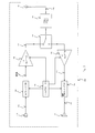
- Now refer to Fig. 2 and 3 for details on the physical layer of the system. In transmit mode, the base 100 receives an analog input signal 112 from the
audio signal source 110 and feeds to theRF modulator 120. The RF modulator 120 synthesizes a digitally modulatedcarrier signal 122 at frequency about 2400Mhz. The modulatedcarrier signal 122 then goes through aRF buffer stage 130 which filters and amplifiessignal 122. ThisRF buffer stage 130 is designed with two purposes. Firstly it is used to isolate the RF modulator 120 from strong radiation received by theantenna 180. This strong radiation arises from the proximity of the base to theaudio signal source 110 which may be a high power radiator like a cellular phone with radiation magnitude in the unit watt range. Secondly it is used to adjust the magnitude of thecarrier 122 so that the radiated power through theantenna 180 is in the micro-watt magnitude. Now theoutput signal 132 fromRF buffer 130 is fed to theRF switch 140 which is controlled by thecontroller 190. Then signal 132 passes through a band-pass filter 170 and radiates through theantenna 180 which is designed to radiate in a directional fashion. The band-pass filter 170 is preferred to be of the SAW (Surface Acoustic Wave) type for its small form factor and high out-of-band rejection. Theantenna 180 may be a wire loop antenna or a micro-strip antenna with narrow bandwidth and high directivity, considering the small size of the chassis, these types of antennae are most suitable. As is well-known, there are commercially available micro-strip antennae built with material of very high dielectric coefficient such that the size can be shrunk comparably to a finger nail at frequency about 2400Mhz. If cost factor is more important, then a wire loop antenna is also acceptable with higher loss. - In receive mode, the base 100 receives a modulated
carrier signal 232, fromantenna 180, through the band-pass filter 170 and theRF switch 140, transmitted from the headphone. Thesignal 232 then passes through aRF buffer 150. This buffer is designed to have a narrow bandwidth and low gain. The reason being that the communication range is limited to a few metres and that radiation immunity is the most important factor of all. Now theconditioned signal 234 from thebuffer 150 enters theRF demodulator 160 which recovers theaudio signal 212 from themicrophone 210 of the headphone. Theaudio signal 212 is fed to theaudio signal destination 102. - The
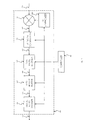
headset 200 operates essentially the same way as the base 100. The headphone receives an analog input signal 212 from themicrophone 210 and feeds to theRF modulator 120. The RF modulator synthesizes a digitally modulatedcarrier signal 222 at frequency the same as thesignal 122. Thesignal 222 then goes through aRF buffer stage 130 which filters and amplifies thesignal 222. Now theoutput signal 232 fromRF buffer 130 is fed to theRF switch 140 which is controlled by thecontroller 190. Then signal 232 passes through a band-pass filter 170 and radiates through theantenna 180 which is designed to radiate in a directional fashion. It should be noted thatsignal 132 transmitted from the base has exactly the same characteristics as thesignal 232 transmitted from the headphone. The two signals are short bursts which happens alternately in time sequence. - Similar to the base, the
headphone 200 receives the modulatedcarrier signal 132, fromantenna 180, transmitted from the headphone. It goes through the same processing as in the base and finally the sourceaudio signal 112 from the base is recovered and fed tospeaker 202. - Now refer to Fig. 4 which is a functional block diagram of the modular 120 configured for use in the base. In VCS, the source
audio signal 112 enters theaudio signal encoder 121 which digitally encodes thesignal 112 forming an encodeddata stream 123 preferably at 32 KHz. The encoder may be, by way of unlimited example, CVSD, PCM, ADPCM or the like. The data rate of 32 KHz is a reasonable choice judging on overall quality and cost. Thedata stream 123 enters a first-in-first-out memory buffer (FIFO) 124 and is stored until thecontroller 190 commands it to stream out data at a rate higher than twice the rate of thedata stream 123 formingdata stream 125. Thisdata stream 125 further enters adata packet encoder 126 which adds the synchronization field before the data stream and the error check field after the data stream to form thecomplete data packet 127 which is the VDP. Thus, in a preferred implementation the audio data stream is in fact expanded to form the audio data packets. A segment of the second data stream from the FIFO is packed together with the synchronization field and error check field to form an audio data packet. Therefore, the data packets have three times the size of the audio data stream. Thedata packet 127 is preferably at a rate of approximately three times the rate ofdata stream 123. It should be understood that the preferred choice of data packet rate is approximately the lowest possible, and that higher rate is in no sense limited in this invention. It is preferred for the reason of lessening the speed requirement of the FIFO memory buffer, data packet encoder and the controller, thereby reducing power and memory size. In SHS, thecontroller 190 will provide data for the data packet forming the CDP which is at the same data rate as the VDP but preferably with shorter middle field. The reason being that the shorter the CDP, the less chance of transmission collision. Now thedata packet 127 which is in physical form a burst of pulse signal preferably at 96KHz (i.e. 3x32KHz), goes through a resistive divider (potential divider) so that its amplitude is adjusted suitably to become themodulation input 902 of theRF synthesizer 900. The frequency of theRF synthesizer 900 is programmed by thecontroller 190 to produce a digitally modulatedcarrier signal 122. - Refer to Fig. 5 which is a functional block diagram of the
demodulator 160. Theconditioned signal 234 which is a short burst of transmission from the headphone enters firstly amixer 161 which down coverts thesignal 234 to a lowerintermediate frequency 162. The down conversion is a traditional multiplication type with the local oscillator provided by theRF synthesizer 900. Note thatsynthesizer 900 creates oscillations at appropriate frequencies alternately at transmit and receive. The frequency of 900 is simply programmed by thecontroller 190. Now theIF 162 enters an IF digital demodulator which recovers thedata packet 127. This IF digital demodulator is implement with an IC as are readily commercially available, suitable examples are the type, 13155, 13156 or the likes. Thedata packet 127 is sent to a data packet decoder which checks for synchronization, recovers or checks for transmission errors, and decode the middle field for identity, command and data. The controller will interpret the command, identity and any other data not relevant with voice encoding and performs all necessary action such as matching identity, battery condition of the headphone or any other information seem appropriate. Thevoice encoding data 166 will enter aFIFO memory buffer 167 and will be streamed out as the original encodeddata stream 123.Data stream 123 will enter a digital audio decoder and theoriginal audio signal 212, which is the audio signal input at the microphone of the headphone, is recovered. - Refer to Fig.6 for an explanation of the operation of the RF synthesizer 900 (i.e. programmable frequency synthesizer). It essentially contains a phase lock loop (PLL) programmed by the
controller 190. Thereference oscillator 940 provides a reference frequency which is used to compare the phase of the divide-down frequency of the voltage controlled oscillator (VCO) 910. The phase error voltage is integrated and low-pass filtered by 920 and the resultant DC offset voltage is used to control the VCO. The VCO can be modulated by amodulation input 902 which is a digital base-band signal in this preferred embodiment. The PLL integrated circuit contains a phase detector and a controllable frequency divider. - In preferred embodiments the power radiated from the headset is approximately 10 microwatts. 10 microwatts of power is a reasonable output to attain the necessary range with a reasonable signal to noise ratio. To have a feel for this power, we can calculate the temperature rise of a gram of water after it has been exposed to this power source for one hour. By definition: 1 watt = 1 joule/second; 1 joule = 0.239 calorie; and a calorie is the amount of heat required to raise the temperature of one gram of water by one degree Celsius at atmospheric pressure. Therefore the temperature rise, t, in degree Celsius, of a gram of water exposed to a power source of 10 microwatt for one hour, an be calculated by:
- One can see that this is almost negligible. For human tissue, one can expect the same effect because it is more than 90% composed of water. Further more, the radiation of the transmitter is dispersed in a wide angle probably more than 60 degree (with a micro strip antenna), therefore the radiated energy directed towards the head is much less than 10 microwatt. With this reasoning, one can conclude that this energy level is totally safe for the user. As a matter of interest, one watt of power will induce a temperature rise of 860 degrees. This is the magnitude of power of GSM phone. With a narrow beam antenna, one will expect some malignant effect.
- Preferably, the communication between the base unit and head set may be in a frequency channel or channels lying in the range 2200 to 2600MHz, or more preferably in the range 2400 - 2500MHz. The choice of these frequency bands is based on the following factors:
- 1) Unlicensed operated world wide - these are the only frequency bands with world wide acceptance without needing an operation license.
- 2) Wide bandwidth available - considering the density of the cellular phone users a very wide bandwidth must be available for expected heavy usage, thus these are the most appropriate bands.
- 3) Size - as described these frequency bands allow very small RF antenna and filter sizes as opposed to other available unlicensed bands in much lower frequency ranges (below 900 MHz).
- 4) High radiation efficiency - considering the very small size of the printed circuit board, the radiation ground plane is very small. At lower frequency, one would expect the addition of amplifiers in transmission and reception circuits to be necessary because of lower radiation efficiency, which certainly would increase power consumption.
-
Claims (16)
- Communication apparatus for providing a wire-less two-way audio link between a person and apparatus having an audio output and an audio input, the communication apparatus comprising:a base unit; anda head-set,the base unit comprising an input for receiving an audio signal from the audio output, an encoder for encoding a first carrier signal with the received audio signal, and a transmitter for transmitting the audio-encoded carrier signal to the head-set,the head-set being adapted to be worn on the person's head and comprising a receiver for receiving the audio encoded carrier signal from the base unit, a decoder for decoding the received signal, a speaker for outputting the decoded signal to the person, a microphone for detecting the person's voice and generating a voice signal, an encoder for encoding a second carrier signal with the voice signal, the frequencies of said first and second carrier signals lying in a common frequency channel, and a transmitter for transmitting the voice-encoded carrier signal to the base unit,the base unit further comprising a receiver for receiving the voice-encoded carrier signal, a decoder for decoding the received signal, and an output for outputting the decoded signal to said audio input,the base unit and head-set each further comprising a respective controller connected to the respective encoder, transmitter, receiver and decoder,at least one of the controllers being arranged to send a synchronization signal to the other controller,the controllers being arranged to synchronize operation of the transmitters and receivers such that the audio-encoded and voice-encoded carrier signals are transmitted in alternate time intervals, to provide time division duplex communication between the base unit and head-set on said frequency channel.
- Communication apparatus in accordance with claim 1, wherein each encoder is arranged to digitally encode the respective carrier signal with the received audio signal or voice signal.
- Communication apparatus in accordance with any preceding claim wherein the encoder of the base unit comprises a first frequency synthesizer and the decoder of the base unit comprises the same first frequency synthesizer, the frequency generated by the synthesizer being controlled by the controller according to whether the base unit is transmitting or receiving,
the encoder and decoder of the head-set similarly sharing a second frequency synthesizer controlled by the head-set controller. - Communication apparatus in accordance with claim 3 wherein the first and second frequency synthesizers each comprise a respective reference oscillator, phase detector, frequency divider, integrator, low-pass filter and voltage controlled oscillator (VCO)arranged as a phase lock loop, the frequency divider being controlled by the controller to set the output frequency of the VCO, the VCO further comprising a modulation input.
- Communication apparatus for providing a wire-less, two-way audio link between a person and apparatus having an audio output and an audio input, the communication apparatus comprising:a base unit; anda head-set,the base unit comprising an input for receiving an audio signal from the apparatus audio output, a converter for converting the audio signal to a digital audio data stream, a data packet encoder for receiving the audio data stream and forming discrete audio data packets, and a transmitter for transmitting the audio data packets to the head-set using a first carrier signal,the head-set comprising a receiver for receiving the transmitted audio data packets, a signal reconstructor for reconstructing the audio signal from the received audio data packets, and a speaker for outputting the reconstructed audio signal to the person, the head-set further comprising a microphone arranged to generate a voice signal indicative of the person's vocal output,a converter for converting the voice signal to a digital voice data stream, a data packet encoder for receiving the voice data stream and forming discrete voice data packets, and a transmitter for transmitting the voice data packets to the base unit using a second carrier signal, the frequencies of said first and second carrier signals lying in a common frequency channel;the base unit further comprising a receiver for receiving the transmitted voice data packets, a signal reconstructor for reconstructing the voice signal from the received voice data packets, and an output for outputting the reconstructed voice signal to the apparatus audio input,the base unit and head-set each further comprising a respective controller connected to the respective converter, data packet encoder, transmitter, receiver, and signal reconstructor, at least one of the controllers being arranged to send a synchronisation signal to the other controller,the controllers being arranged to synchronise operation of the transmitters and receivers such that the audio data packets and voice data packets are transmitted alternately to provide time division duplex communication between the base unit and head-set on said frequency channel.
- Communication apparatus in accordance with any preceding claim, wherein said first and second carrier signals are radio frequency (RF) signals.
- Communication apparatus in accordance with any preceding claim wherein said common frequency channel lies in the range 2200 to 2600MHz.
- Communication apparatus in accordance with any preceding claim, wherein said first and second carrier signals each have a frequency of approximately 2400MHz.
- Communication apparatus in accordance with any preceding claim, wherein the base unit and head set each comprise a respective transceiver which provides said transmitter and receiver, the transceiver being switchable between a transmitter mode and a receiver mode in response to a control signal from the respective controller.
- Communication apparatus in accordance with any preceding claim wherein the head-set is arranged such that the maximum power radiated from it does not exceed 10 micro watts.
- Communication apparatus in accordance with any preceding claim, wherein said apparatus having an audio output and an audio input is a mobile telephone, and the base unit is adapted to interface with the mobile telephone.
- A method of providing a two way audio link between a person and apparatus having an audio output and an audio input, the method comprising the steps of: receiving at a base unit an audio signal from the audio output;generating a first carrier signal in a first frequency range;encoding the first carrier signal with the audio signal;transmitting the audio-encoded first carrier signal from the base unit to a head-set worn on the person's head;decoding the received audio-encoded signal in the head-set;outputting the decoded signal to the person via a speaker;generating a voice signal indicative of the person's vocal output using a microphone;generating a second carrier signal in the head-set in said first frequency range;encoding the second RF carrier signal with the voice signal;transmitting the voice-encoded second carrier signal from the head set to the base unit;decoding the received voice-encoded signal in the base unit, andoutputting the decoded signal to said audio input,the method further comprising the steps of transmitting a synchronisation signal from at least one of the base unit and head-set to the other; andsynchronizing said transmitting steps such that the audio and voice encoded signals are transmitted in alternate time intervals to provide time division duplex communication between the base unit and head-set in said first frequency range.
- A method of providing a two-way audio link between a person and apparatus having an audio input and an audio output, the method comprising the steps of:receiving at a base unit an audio signal from the audio output;converting the audio signal to a digital audio data stream;forming the audio data stream into discrete audio data packets;transmitting the audio data packets to a head-set using a first carrier signal;receiving the transmitted audio data packets at the head-set;reconstructing the audio signal at the head-set from the received audio data packets;outputting the reconstructed audio signal to the person via a speaker;detecting the person's vocal output using a head-set microphone;converting the microphone signal to a digital voice data stream;forming the voice data stream into discrete voice data packets;transmitting the voice data packets to the base unit using a second carrier signal, the frequencies of said first and second carrier signals lying in a common frequency channel;receiving the transmitted voice data packets at the base unit;reconstructing the microphone signal at the base unit from the received voice data packets; andoutputting the reconstructed microphone signal to the apparatus audio input,the method further comprising the steps of:transmitting a synchronisation signal from at least one of the base unit and head-set to the other;receiving the synchronisation signal at the base unit or head-set respectively; andsynchronising said transmitting steps such that the audio data packets and voice data packets are transmitted alternately to provide time division duplex communication between the base unit and head-set on said frequency channel.
- A method in accordance with any one of claims 12 or 13, further comprising the steps of:monitoring the intensity of said received audio signal and the intensity of the signal output to the apparatus audio input: andterminating transmission of the audio-encoded first carrier signal or the audio data packets respectively, in response to both intensities remaining below respective predetermined thresholds for a predetermined time interval.
- A method in accordance with claim 14, further comprising the steps of:exchanging between the base unit and head-set synchronization hand-shake signals (SHS signals) at predetermined time intervals while both said intensities remain below their respective thresholds, the SHS signals being modulated signals transmitted on a predetermined command channel in alternate time intervals in Time Division Duplex fashion; andswitching the base unit and head-set to respective low-power-consumption modes between said SHS signals.
- A method in accordance with claim 15, further comprising the steps of:searching for an empty communication channel in response to the received audio signal exceeding its predetermined threshold;sending an SHS signal to the head-set from the base unit after finding an empty channel, the SHS signal containing information identifying the empty channel;setting said first and second carrier frequencies to lie in said empty channel; andcommencing or recommencing transmission of said audio and voice encoded signals or said audio and voice data packets respectively in time division duplex fashion on said empty channel.
Priority Applications (3)
| Application Number | Priority Date | Filing Date | Title |
|---|---|---|---|
| EP00301589A EP1133135B1 (en) | 2000-02-29 | 2000-02-29 | Communication apparatus and method |
| CN00106919A CN1311565A (en) | 2000-02-29 | 2000-04-21 | Communication device and method |
| JP2000124357A JP2001257620A (en) | 2000-02-29 | 2000-04-25 | Communication unit and method |
Applications Claiming Priority (1)
| Application Number | Priority Date | Filing Date | Title |
|---|---|---|---|
| EP00301589A EP1133135B1 (en) | 2000-02-29 | 2000-02-29 | Communication apparatus and method |
Publications (2)
| Publication Number | Publication Date |
|---|---|
| EP1133135A1 true EP1133135A1 (en) | 2001-09-12 |
| EP1133135B1 EP1133135B1 (en) | 2003-07-09 |
Family
ID=8172748
Family Applications (1)
| Application Number | Title | Priority Date | Filing Date |
|---|---|---|---|
| EP00301589A Expired - Fee Related EP1133135B1 (en) | 2000-02-29 | 2000-02-29 | Communication apparatus and method |
Country Status (3)
| Country | Link |
|---|---|
| EP (1) | EP1133135B1 (en) |
| JP (1) | JP2001257620A (en) |
| CN (1) | CN1311565A (en) |
Cited By (1)
| Publication number | Priority date | Publication date | Assignee | Title |
|---|---|---|---|---|
| WO2002080503A1 (en) * | 2001-03-30 | 2002-10-10 | Alban Sayag | Wireless assembly comprising an ear pad and an intermediate module connected to a mobile telephone |
Families Citing this family (10)
| Publication number | Priority date | Publication date | Assignee | Title |
|---|---|---|---|---|
| CN100423460C (en) * | 2002-10-10 | 2008-10-01 | 讯宝科技公司 | WLAN communications system |
| US7400912B2 (en) | 2002-10-10 | 2008-07-15 | Symbol Technologies, Inc. | Wlan communications system |
| US7817960B2 (en) | 2007-01-22 | 2010-10-19 | Jook, Inc. | Wireless audio sharing |
| EP2489116B1 (en) * | 2009-10-14 | 2018-07-25 | ABB Research Ltd. | Wireless control of power network switching devices |
| CN104602368B (en) * | 2014-12-18 | 2018-06-08 | 小米科技有限责任公司 | Mobile terminal |
| US9713192B2 (en) * | 2015-03-27 | 2017-07-18 | Intel Corporation | Device and method for processing audio data |
| WO2018178400A1 (en) | 2017-03-31 | 2018-10-04 | British Telecommunications Public Limited Company | Method and apparatus for transmitting signals over wire connections |
| WO2018178209A1 (en) | 2017-03-31 | 2018-10-04 | British Telecommunications Public Limited Company | Method and apparatus for transmitting signals over wire connections |
| EP3577775B1 (en) | 2017-03-31 | 2020-11-18 | British Telecommunications Public Limited Company | Method and apparatus for transmitting signals over wire connections |
| US10819498B2 (en) * | 2017-03-31 | 2020-10-27 | British Telecommunications Public Limited Company | Method and apparatus for transmitting signals over a wire connection |
Citations (7)
| Publication number | Priority date | Publication date | Assignee | Title |
|---|---|---|---|---|
| US4882745A (en) * | 1987-05-08 | 1989-11-21 | Silver Alan H | Cordless headset telephone |
| US5375174A (en) * | 1993-07-28 | 1994-12-20 | Noise Cancellation Technologies, Inc. | Remote siren headset |
| US5590417A (en) * | 1993-06-03 | 1996-12-31 | Ericsson Inc. | Radiotelephone apparatus including a wireless headset |
| EP0840465A2 (en) * | 1996-10-31 | 1998-05-06 | Nokia Mobile Phones Ltd. | User interface for mobile telephone |
| US5896375A (en) * | 1996-07-23 | 1999-04-20 | Ericsson Inc. | Short-range radio communications system and method of use |
| GB2333420A (en) * | 1998-01-14 | 1999-07-21 | Nokia Mobile Phones Ltd | Remote headset for a mobile phone |
| US5983100A (en) * | 1996-03-14 | 1999-11-09 | Telefonaktiebolaget Lm Ericsson | Circuit assembly for effectuating communication between a first and a second locally-positioned communication device |
-
2000
- 2000-02-29 EP EP00301589A patent/EP1133135B1/en not_active Expired - Fee Related
- 2000-04-21 CN CN00106919A patent/CN1311565A/en active Pending
- 2000-04-25 JP JP2000124357A patent/JP2001257620A/en active Pending
Patent Citations (7)
| Publication number | Priority date | Publication date | Assignee | Title |
|---|---|---|---|---|
| US4882745A (en) * | 1987-05-08 | 1989-11-21 | Silver Alan H | Cordless headset telephone |
| US5590417A (en) * | 1993-06-03 | 1996-12-31 | Ericsson Inc. | Radiotelephone apparatus including a wireless headset |
| US5375174A (en) * | 1993-07-28 | 1994-12-20 | Noise Cancellation Technologies, Inc. | Remote siren headset |
| US5983100A (en) * | 1996-03-14 | 1999-11-09 | Telefonaktiebolaget Lm Ericsson | Circuit assembly for effectuating communication between a first and a second locally-positioned communication device |
| US5896375A (en) * | 1996-07-23 | 1999-04-20 | Ericsson Inc. | Short-range radio communications system and method of use |
| EP0840465A2 (en) * | 1996-10-31 | 1998-05-06 | Nokia Mobile Phones Ltd. | User interface for mobile telephone |
| GB2333420A (en) * | 1998-01-14 | 1999-07-21 | Nokia Mobile Phones Ltd | Remote headset for a mobile phone |
Cited By (1)
| Publication number | Priority date | Publication date | Assignee | Title |
|---|---|---|---|---|
| WO2002080503A1 (en) * | 2001-03-30 | 2002-10-10 | Alban Sayag | Wireless assembly comprising an ear pad and an intermediate module connected to a mobile telephone |
Also Published As
| Publication number | Publication date |
|---|---|
| EP1133135B1 (en) | 2003-07-09 |
| CN1311565A (en) | 2001-09-05 |
| JP2001257620A (en) | 2001-09-21 |
Similar Documents
| Publication | Publication Date | Title |
|---|---|---|
| US6519448B1 (en) | Personal, self-programming, short-range transceiver system | |
| US8442596B2 (en) | Hearing assistive system with low power interface | |
| US5982764A (en) | Time-multiplexed short-range magnetic communications | |
| US5590417A (en) | Radiotelephone apparatus including a wireless headset | |
| US7877121B2 (en) | Modular wireless headset and/or headphones | |
| US20070086601A1 (en) | Flexible wireless air interface system | |
| EP0585030A1 (en) | Infrared link between a transceiver and an external device | |
| US20050100182A1 (en) | Hearing instrument having a wireless base unit | |
| US20070149261A1 (en) | Wireless stereo headset | |
| CN106877897A (en) | Radio frequency communication devices | |
| EP1133135B1 (en) | Communication apparatus and method | |
| JPH11511301A (en) | Hearing aid with wireless remote processor | |
| US20050186993A1 (en) | Communication apparatus for playing sound signals | |
| KR20160105907A (en) | Bluetooth transmission and reception device with antenna in ear hook and method therefor | |
| KR100692176B1 (en) | Wireless Microphone Transmitter-Receiver Device | |
| JP3232038B2 (en) | Wireless transceiver | |
| WO1998052295A1 (en) | Short-range wireless audio communications using induction | |
| CN212367517U (en) | Microphone device and system | |
| JP4708390B2 (en) | Listening system | |
| KR100655102B1 (en) | A wireless f.m. stereo transmitter for a cellular phone | |
| WO1998006183A1 (en) | Remote control for a mobile station | |
| GB2364846A (en) | Split mobile phone handset. | |
| JP2588300B2 (en) | Portable handset | |
| KR200229557Y1 (en) | Wireless digital earmicphone for cellular phone | |
| WO2015110172A1 (en) | Arrangement with a handset device, an interface unit and a hearing device |
Legal Events
| Date | Code | Title | Description |
|---|---|---|---|
| PUAI | Public reference made under article 153(3) epc to a published international application that has entered the european phase |
Free format text: ORIGINAL CODE: 0009012 |
|
| 17P | Request for examination filed |
Effective date: 20010315 |
|
| AK | Designated contracting states |
Kind code of ref document: A1 Designated state(s): AT BE CH CY DE DK ES FI FR GB GR IE IT LI LU MC NL PT SE |
|
| AX | Request for extension of the european patent |
Free format text: AL;LT;LV;MK;RO;SI |
|
| GRAG | Despatch of communication of intention to grant |
Free format text: ORIGINAL CODE: EPIDOS AGRA |
|
| AKX | Designation fees paid |
Free format text: GB |
|
| REG | Reference to a national code |
Ref country code: DE Ref legal event code: 8566 |
|
| GRAG | Despatch of communication of intention to grant |
Free format text: ORIGINAL CODE: EPIDOS AGRA |
|
| GRAH | Despatch of communication of intention to grant a patent |
Free format text: ORIGINAL CODE: EPIDOS IGRA |
|
| GRAH | Despatch of communication of intention to grant a patent |
Free format text: ORIGINAL CODE: EPIDOS IGRA |
|
| GRAA | (expected) grant |
Free format text: ORIGINAL CODE: 0009210 |
|
| AK | Designated contracting states |
Designated state(s): GB |
|
| REG | Reference to a national code |
Ref country code: GB Ref legal event code: FG4D |
|
| PGFP | Annual fee paid to national office [announced via postgrant information from national office to epo] |
Ref country code: GB Payment date: 20040216 Year of fee payment: 5 |
|
| PLBE | No opposition filed within time limit |
Free format text: ORIGINAL CODE: 0009261 |
|
| STAA | Information on the status of an ep patent application or granted ep patent |
Free format text: STATUS: NO OPPOSITION FILED WITHIN TIME LIMIT |
|
| 26N | No opposition filed |
Effective date: 20040414 |
|
| PG25 | Lapsed in a contracting state [announced via postgrant information from national office to epo] |
Ref country code: GB Free format text: LAPSE BECAUSE OF NON-PAYMENT OF DUE FEES Effective date: 20050228 |
|
| GBPC | Gb: european patent ceased through non-payment of renewal fee |
Effective date: 20050228 |
|
| REG | Reference to a national code |
Ref country code: HK Ref legal event code: WD Ref document number: 1042393 Country of ref document: HK |