EP1133965A2 - Absorbent article - Google Patents
Absorbent article Download PDFInfo
- Publication number
- EP1133965A2 EP1133965A2 EP01302119A EP01302119A EP1133965A2 EP 1133965 A2 EP1133965 A2 EP 1133965A2 EP 01302119 A EP01302119 A EP 01302119A EP 01302119 A EP01302119 A EP 01302119A EP 1133965 A2 EP1133965 A2 EP 1133965A2
- Authority
- EP
- European Patent Office
- Prior art keywords
- leakage preventing
- side wall
- preventing side
- free end
- corrugations
- Prior art date
- Legal status (The legal status is an assumption and is not a legal conclusion. Google has not performed a legal analysis and makes no representation as to the accuracy of the status listed.)
- Granted
Links
- 230000002745 absorbent Effects 0.000 title claims abstract description 27
- 239000002250 absorbent Substances 0.000 title claims abstract description 27
- 230000003405 preventing effect Effects 0.000 claims abstract description 93
- 239000004745 nonwoven fabric Substances 0.000 claims abstract description 47
- 239000007788 liquid Substances 0.000 claims abstract description 36
- 239000000835 fiber Substances 0.000 claims abstract description 11
- 229920001169 thermoplastic Polymers 0.000 claims abstract description 5
- 239000004416 thermosoftening plastic Substances 0.000 claims abstract description 5
- 230000001747 exhibiting effect Effects 0.000 claims abstract description 3
- 238000007493 shaping process Methods 0.000 description 47
- 239000010410 layer Substances 0.000 description 15
- 238000005452 bending Methods 0.000 description 10
- 239000008280 blood Substances 0.000 description 8
- 210000004369 blood Anatomy 0.000 description 8
- 230000002175 menstrual effect Effects 0.000 description 8
- 230000004048 modification Effects 0.000 description 8
- 238000012986 modification Methods 0.000 description 8
- 230000002209 hydrophobic effect Effects 0.000 description 7
- 239000010808 liquid waste Substances 0.000 description 4
- 229920005989 resin Polymers 0.000 description 4
- 239000011347 resin Substances 0.000 description 4
- 239000004744 fabric Substances 0.000 description 3
- 239000004750 melt-blown nonwoven Substances 0.000 description 3
- 230000037303 wrinkles Effects 0.000 description 3
- 239000012790 adhesive layer Substances 0.000 description 2
- 239000002131 composite material Substances 0.000 description 2
- 230000001788 irregular Effects 0.000 description 2
- 239000000203 mixture Substances 0.000 description 2
- 229920000642 polymer Polymers 0.000 description 2
- 230000000630 rising effect Effects 0.000 description 2
- 210000002700 urine Anatomy 0.000 description 2
- 244000043261 Hevea brasiliensis Species 0.000 description 1
- 239000002648 laminated material Substances 0.000 description 1
- 238000002844 melting Methods 0.000 description 1
- 230000008018 melting Effects 0.000 description 1
- 229920003052 natural elastomer Polymers 0.000 description 1
- 229920001194 natural rubber Polymers 0.000 description 1
- 208000024335 physical disease Diseases 0.000 description 1
- 229920002635 polyurethane Polymers 0.000 description 1
- 239000004814 polyurethane Substances 0.000 description 1
- 239000005871 repellent Substances 0.000 description 1
- 230000000717 retained effect Effects 0.000 description 1
- 229920003048 styrene butadiene rubber Polymers 0.000 description 1
- 230000001360 synchronised effect Effects 0.000 description 1
- 229920003051 synthetic elastomer Polymers 0.000 description 1
- 239000012209 synthetic fiber Substances 0.000 description 1
- 229920002994 synthetic fiber Polymers 0.000 description 1
- 239000005061 synthetic rubber Substances 0.000 description 1
- 229920005992 thermoplastic resin Polymers 0.000 description 1
Images


Classifications
-
- A—HUMAN NECESSITIES
- A61—MEDICAL OR VETERINARY SCIENCE; HYGIENE
- A61F—FILTERS IMPLANTABLE INTO BLOOD VESSELS; PROSTHESES; DEVICES PROVIDING PATENCY TO, OR PREVENTING COLLAPSING OF, TUBULAR STRUCTURES OF THE BODY, e.g. STENTS; ORTHOPAEDIC, NURSING OR CONTRACEPTIVE DEVICES; FOMENTATION; TREATMENT OR PROTECTION OF EYES OR EARS; BANDAGES, DRESSINGS OR ABSORBENT PADS; FIRST-AID KITS
- A61F13/00—Bandages or dressings; Absorbent pads
- A61F13/15—Absorbent pads, e.g. sanitary towels, swabs or tampons for external or internal application to the body; Supporting or fastening means therefor; Tampon applicators
- A61F13/45—Absorbent pads, e.g. sanitary towels, swabs or tampons for external or internal application to the body; Supporting or fastening means therefor; Tampon applicators characterised by the shape
- A61F13/47—Sanitary towels, incontinence pads or napkins
- A61F13/475—Sanitary towels, incontinence pads or napkins characterised by edge leakage prevention means
- A61F13/4751—Sanitary towels, incontinence pads or napkins characterised by edge leakage prevention means the means preventing fluid flow in a transversal direction
- A61F13/4752—Sanitary towels, incontinence pads or napkins characterised by edge leakage prevention means the means preventing fluid flow in a transversal direction the means being an upstanding barrier
- A61F13/4753—Sanitary towels, incontinence pads or napkins characterised by edge leakage prevention means the means preventing fluid flow in a transversal direction the means being an upstanding barrier the barrier being not integral with the topsheet or backsheet
-
- A—HUMAN NECESSITIES
- A61—MEDICAL OR VETERINARY SCIENCE; HYGIENE
- A61F—FILTERS IMPLANTABLE INTO BLOOD VESSELS; PROSTHESES; DEVICES PROVIDING PATENCY TO, OR PREVENTING COLLAPSING OF, TUBULAR STRUCTURES OF THE BODY, e.g. STENTS; ORTHOPAEDIC, NURSING OR CONTRACEPTIVE DEVICES; FOMENTATION; TREATMENT OR PROTECTION OF EYES OR EARS; BANDAGES, DRESSINGS OR ABSORBENT PADS; FIRST-AID KITS
- A61F13/00—Bandages or dressings; Absorbent pads
- A61F13/15—Absorbent pads, e.g. sanitary towels, swabs or tampons for external or internal application to the body; Supporting or fastening means therefor; Tampon applicators
- A61F13/45—Absorbent pads, e.g. sanitary towels, swabs or tampons for external or internal application to the body; Supporting or fastening means therefor; Tampon applicators characterised by the shape
- A61F13/47—Sanitary towels, incontinence pads or napkins
- A61F13/475—Sanitary towels, incontinence pads or napkins characterised by edge leakage prevention means
Definitions
- the present invention relates mainly to an absorbent article for absorbing and retaining a liquid waste such as menstrual blood and, more particularly, to an absorbent article having leakage preventing side walls on the two widthwise sides of the liquid receiving side.
- absorbent articles including a sanitary napkin, a urine absorbing pad and a disposable diaper. These absorbent articles are demanded, when worn, for absorbing the liquid waste reliably in liquid absorbing layers so that the liquid waste may not leak to the outside of the absorbent articles.
- absorbent article which is provided on the surface of the liquid receiving side with leakage preventing side walls extending longitudinally on the two widthwise sides.
- a longitudinally extending unstretchable hydrophobic sheet is jointed to the top sheet of the absorbent article, and an elastic member extending longitudinally of the absorbent article is jointed to the hydrophobic sheet.
- this hydrophobic sheet is irregularly wrinkled by the longitudinal elastic shrinking forces of the elastic members. If the unstretchable hydrophobic sheet thus has many irregular wrinkles in which the ridges and valleys are individually extended in the widthwise direction and are repeated in the longitudinal direction, the leakage preventing side walls acquire a high bending rigidity in the widthwise direction so that they become planar in the widthwise direction. Then, the leakage preventing side walls hardly follow the shape of the skin surface of a wearer so that the wearer feels a sense of discomfort.
- the hydrophobic sheet being subjected to the elastic shrinking force is rounded or irregularly folded on the liquid receiving side of the absorbent article being worn. Then, the contact between the leakage preventing side walls and the wearer's skin becomes unstable to form a clearance easily between the leakage preventing side walls and the skin. In this case, the sideway leakage cannot be completely prevented.
- the invention has an object to provide an absorbent article which is enabled to curve the leakage preventing side walls easily in the widthwise direction to form a three-dimensional stereoscopic shape according to the shape of the skin of a wearer, by forming regions having a high bending rigidity in the widthwise direction, in advance in the leakage preventing side walls to be subjected to a shrinking force by elastic members and by making a rigidity difference in the widthwise direction.
- an absorbent article comprising: a main body including a support sheet, a liquid absorbing layer laid on the support sheet, and a liquid-permeable sheet provided on a liquid receiving side of the main body and covering the liquid absorbing layer; and leakage preventing side walls provided on two sides of the main body lying opposite one another in the widthwise direction and extending in the longitudinal direction, to have root ends jointed to the surface of the liquid receiving side and to have free ends positioned apart from the surface of the liquid receiving side, wherein each leakage preventing side wall includes: a nonwoven fabric comprising thermoplastic fibers; and an elastic member for exhibiting an elastic shrinking force in the longitudinal direction, wherein the nonwoven fabric is provided with: at least two rigid regions having corrugations, ridges and valleys of which are individually extended in a direction from the root end to the free end of the leakage preventing side wall and are repeated regularly in the longitudinal direction; and a rigid boundary portion in which the corrugations are discontinuous and which is extended in the longitudinal direction mid
- the nonwoven fabric making the leakage preventing side wall contains the thermoplastic fibers and is pressure/heat-shaped to form the regular corrugations.
- the ridges and valleys of the corrugations are individually extended in the widthwise direction on the leakage preventing side wall so that the rigid regions having the corrugations are higher in the widthwise bending rigidity. Therefore, the rigid regions are not extremely bent by an external force but can keep the extended state in the widthwise direction. Since the rigid boundary portion is formed midway between the root end and the free end, however, the leakage preventing side wall can be easily bent and deformed in the widthwise direction across the rigid boundary portion.
- the leakage preventing side walls can be easily curved in the widthwise direction according to the curved shape of the skin of the wearer so that they can take the three-dimensional stereoscopic shapes easily. As a result, the leakage preventing side walls can come into close contact with the skin to prevent the sideway leakage effectively.
- the leakage preventing side walls are made of the nonwoven fabric, they are sufficiently soft. If the corrugations are given a pitch as fine as 0.3 to 1.5 mm or more preferably about 0.5 to 1.0 mm, moreover, the leakage preventing side walls come into soft abutment against the skin so that the wearer hardly feels the sense of discomfort.
- a band-shaped region in which the nonwoven fabric is not corrugated or is corrugated lower than the corrugations and which is extended in the longitudinal direction, and a boundary line between the corrugations and the band-shaped region is the rigid boundary portion.
- the leakage preventing side wall may have the elastic member attached to the free end but not to the vicinity of the rigid boundary portion.
- the leakage preventing side wall may have the elastic member attached to the vicinity of the rigid boundary portion but not to the free end.
- the leakage preventing side wall may have two elastic members attached to the free end and the vicinity of the rigid boundary portion, respectively.
- the elastic member at the free end has a higher elastic shrinking force than that of the elastic member in the vicinity of the rigid boundary portion.
- the leakage preventing side wall may be made to have at least two sheet portions either by folding a single nonwoven fabric, as extending from the root end, back at the free end to the root end, or by jointing a plurality of nonwoven fabrics, as individually extending from the root end, to one another in the longitudinal direction at the free end or another region, and the rigid regions and the rigid boundary portion may be formed in the individual sheet portions at the same positions of the leakage preventing side wall.
- the leakage preventing side wall is made of the two sheet portions of the nonwoven fabric, its leakage preventing effect as well as its rigidity in the rigid regions can be enhanced, and the leakage preventing side wall can be softly deformed across the rigid boundary portion.
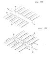
- Fig. 1 is a perspective view showing a sanitary napkin as an absorbent article according to a first embodiment of the invention and taken from a liquid receiving side
- Fig. 2 is a perspective view showing a portion and including a section taken along line II - II of Fig. 1
- Fig. 3 is a section of a leakage preventing side wall shown in Fig. 2
- Fig. 8 is an enlarged perspective view showing a portion of a free end portion of the side wall sheet.
- a sanitary napkin 1 as shown in Figs. 1, 2 and 3, is constructed to have a main body including: a support sheet 2 for confronting an external wear such as an underwear; a liquid absorbing layer 3 positioned on the side of the wearer for absorbing the liquid waste; and a liquid-permeable sheet 4 for covering the surface of the liquid receiving side of the liquid absorbing layer 3.
- Side end portions 4a of the liquid-permeable sheet 4 lying opposite one another in the widthwise direction (or a direction X) are jointed onto the surface of the support sheet 2 on two sides of the liquid absorbing layer 3.
- the individual leakage preventing side walls 5 and 5 are made of one side wall sheet 6.
- the side wall sheet 6 is made of a hydrophobic nonwoven fabric. This side wall sheet 6 is jointed at its one end portion 5a onto the support sheet 2 and the side end portion 4a of the liquid-permeable sheet 4. The side wall sheet 6 is extended away from the support sheet 2 to form one root end 5b of the side wall 5 on the side end portion 4a of the liquid-permeable sheet 4 and is then folded back to form a free end 5c of the side wall 5. Moreover, the side wall sheet 6 is returned to the support sheet 2 and is so jointed at its other end portion 5e to the upper face of the support sheet 2 that another root end 5d of the side wall 5 is formed and jointed onto the side end portion 4a of the liquid-permeable sheet 4. Therefore, the leakage preventing side wall 5 has a double structure in which the two folded portions (or inner and outer sheet portions) of the side wall sheet (of the nonwoven fabric) 6 are overlaid in the widthwise direction (or the direction X).
- the side wall sheet 6 is formed with corrugations 7.
- These corrugations 7 have ridges 7a and valleys 7b repeated in the longitudinal direction (or the direction Y).
- the ridges 7a and the valleys 7b are individually extended in the direction from the root ends 5b and 5d to the free end 5c of the leakage preventing side wall 5.
- the side wall sheet 6 is formed with band-shaped regions 8 and 8a, which are extended in the longitudinal direction (or the direction Y).
- the side wall sheet 6 is never corrugated or is corrugated lower than the aforementioned corrugations to have a smooth or relatively smooth surface.
- the band-shaped regions 8 and 8a may be formed by crushing the corrugations 7 completely or to some degree.
- the side wall sheet 6 is folded back at the band-shaped portion 8 to form the free end 5c of the leakage preventing side wall 5. To this free end 5c, moreover, there is internally jointed an elastic member 9.
- the band-shaped regions 8a are so formed on the leakage preventing side wall 5 midway between the root ends 5b and 5d and the free end 5c as to extend continuously in the longitudinal direction. However, these band-shaped regions 8a may be extended intermittently at an interval in the longitudinal direction. As shown in Fig. 3, the corrugations 7 and the band-shaped regions 8a are formed at substantially equal height positions individually on the inner and outer sheet portions of the side wall sheet 6 (i.e., the two folded portions of the side wall sheet 6 folded back at the free end 5c) composing the leakage preventing side wall 5.
- the inner and outer sheet portions of the side wall sheet 6 may contact each other, as shown in Fig. 3, or may not contact each other, as shown in Fig. 2.
- the regions where the numerous corrugations 7 are regularly formed are rigid regions which have a higher bending rigidity in the direction from the root ends 5b and 5d to the free end 5c (in the widthwise direction or the direction X).
- the band-shaped region 8a is a lower rigid region which has a lower bending rigidity in the direction from the root ends to the free end, as compared with the aforementioned rigid regions having the corrugations 7.
- a rigid boundary portion 11 is located on the boundary line between the rigid region having the corrugations 7 and the lower rigid region (or the band-shaped region 8).
- the side wall sheet 6 is made of a nonwoven fabric having no or little stretchability by itself, but is corrugated at 7, so that it is allowed to exhibit a little elastic shrinking force in the longitudinal direction (or the direction Y) by the extension and shrinkage of the corrugations 7. Since the free end 5c is provided with the elastic member 9, on the other hand, a strong elastic shrinking force acts in the longitudinal direction (or the direction Y) upon the free end 5c.
- the leakage preventing side walls 5 are jointed to the surface of the liquid receiving side of the main body while falling down outwardly in the widthwise direction.
- the sanitary napkin 1 is so curved that its liquid receiving side is recessed in the longitudinal direction (or the direction Y), and the leakage preventing side walls 5 are raised at their free ends 5c apart from the support sheet 2.
- the leakage preventing side walls 5 and 5 are so obliquely raised that the free ends 5c are directed outwardly in the widthwise direction with respect to the root ends 5b and 5d.
- the portions having the corrugations 7 are the rigid regions where the bending rigidity becomes higher in the direction from the root ends 5b and 5d to the free end 5c, but the lower rigid regions, i.e., the band-shaped regions 8a and the rigid boundary portions 11 are formed in the midway regions between the root ends 5b and 5d and the free ends 5c. Therefore, the leakage preventing side walls 5 are easily folded and deformed in the directions (i) and (ii) in Fig. 3 across the band-shaped regions 8a or the rigid boundary portions 11.
- the leakage preventing side walls 5 can be made soft and deformable in the longitudinal direction (or the direction Y) in which the corrugations 7 are arrayed. Therefore, the leakage preventing side walls 5 can be freely deformed as a whole while following the three-dimensional stereoscopic shape according to the shape of the crotch of a wearer's body. In the rigid regions having the corrugations 7, moreover, the bending rigidity is so high as to apply a force to keep the planar shape. There is eliminated a disadvantage that the leakage preventing side walls 5 are irregularly folded or folded back to fail to restorations at the portions having the corrugations 7 other than the band-shaped regions 8a and the rigid boundary portions 11.
- the leakage preventing side walls 5 easily contact with the wearer's skin in accordance with the surface shape of the skin so that the clearance from the skin is hardly formed to enhance the sideway leakage preventing effect.
- the side wall sheets 6 forming the leakage preventing side walls 5 are made of the nonwoven fabric, and the pitch of the corrugations 7 are as fine as no less than 0.3 mm and no more than 1.5 mm, preferably no less than 0.5 mm and no more than 1.0 mm, the leakage preventing side walls 5 softly contact with the skin.
- the leakage preventing side walls 5 are easily deformable into the three-dimensional stereoscopic shape, as described above, so that the wearer hardly feels the sense of discomfort when the leakage preventing side walls come into abutment against the skin.
- the menstrual blood as received on the liquid receiving side of the sanitary napkin 1, is absorbed through the liquid-permeable sheet 4 by the liquid absorbing layer 3.
- the menstrual blood is given to the inner sheet portion (i.e., the portion facing the side of the liquid absorbing layer 3) of the side wall sheet 6 of the leakage preventing side wall 5, it is guided on the surface of the side wall sheet 6 along the valleys 7b of the corrugations 7 onto the liquid-permeable sheet 4.
- the leakage preventing side wall 5 is jointed on the side end portion 4a, as extended sideway of the liquid absorbing layer 3, of the liquid-permeable sheet 4.
- the menstrual blood having migrated over the surface of the side wall sheet 6 to the root end side is fed to the liquid-permeable sheet 4 so that it is easily led to the liquid absorbing layer 3.
- the leakage preventing side walls 5 may be given the structure in which they rise from the central portion, as located between the two side end portions 4a and 4a and covering the liquid absorbing layer 3, of the liquid-permeable sheet 4. With such a structure, also, the menstrual blood having migrated over the surface of the side wall sheet 6 can be easily absorbed through the liquid-permeable sheet 4 by the liquid absorbing layer 3.
- Fig. 9 is a view for explaining a heat-pressing step of forming the corrugations 7 and the band-shaped regions 8a (and the band-shaped regions 8) on the side wall sheet 6 and simultaneously forming the rigid boundary portions 11 in the boundary portion between the corrugations 7 and the band-shaped regions 8a.
- Fig. 9 shows only one band-shaped region 8a, but a plurality of band-shaped regions could be simultaneously formed at a heat-pressing step similar to that of Fig. 9.
- a nonwoven fabric such as a melt-blown nonwoven fabric formed of or containing thermoplastic fibers is heat-pressed by clamping it between shaping rolls 21 and 22.
- These shaping rolls 21 and 22 are turned in directions ⁇ and ⁇ while meshing with each other.
- the shaping roll 21 has a shaping face formed on its surface.
- Fig. 10A develops and shows the top plan view of the shaping face of the surface of the shaping roll 21.
- the shaping face of the shaping roll 21 there are stripe embossed shaping ribs 23 and grooves 24 which are extended in the axial direction of the roll and repeated at a constant pitch in the turning direction (or the direction ⁇ ).
- a bulging circumference 25 which continues to the upper faces of the shaping ribs 23 and is extended continuously in the turning direction (or the direction ⁇ ).
- Fig. 10B develops and shows the shaping face of the surface of the other shaping roll 22.
- the shaping face of the surface of the shaping roll 22 there are stripe embossed shaping ribs 26 and grooves 27 which are extended in the axial direction of the roll and repeated at a constant pitch in the turning direction (or the direction ⁇ ).
- a recessed circumference 28 At the axial central portion of the shaping roll 22, there is formed a recessed circumference 28 which continues to the bottom portions of the grooves 27 and is extended continuously in the turning direction (or the direction ⁇ ).
- the shaping ribs 23 of the shaping roll 21 and the shaping ribs 26 of the shaping roll 22 mesh with each other such that the shaping ribs 23 enter the grooves 27 of the shaping roll 22 whereas the shaping ribs 26 enter the grooves 24 of the shaping roll 21.
- the bulging circumference 25 of the shaping roll 21 bites into the recessed circumference 28 of the shaping roll 22.
- the side wall sheet 6 is made of a melt-blown nonwoven fabric, an air-through nonwoven fabric, a spun-bonded nonwoven fabric, a point-bonded nonwoven fabric, an air-laid nonwoven fabric or the like.
- the side wall sheet 6 may be made of a laminate material of the nonwoven fabric and a resin film.
- These nonwoven fabrics 6A are made of the PE, PP or PET fibers, or composite synthetic fibers of the core-sheath type of the PE/PP or PE/PET or of the side-by-side type thereof.
- Fig. 11A is a section showing the shaping face of the shaping roll 22 and taken along line A - A of Fig. 10B
- Fig. 11B is a section taken along line B - B of Fig. 10B.
- the shaping faces of the shaping rolls 21 and 22 are preferably set to a temperature which is lower by 10°C to 50°C, for example, than the melting point of the thermoplastic resin making the aforementioned nonwoven fabric 6A.
- the array pitch of the shaping ribs 26 in the turning direction (or the direction ⁇ ) is indicated by ⁇ 1
- the exceeding size extending through the shaping ribs 26 and the grooves 27 between the array pitch ⁇ 1 is indicated by ⁇ 2.
- the nonwoven fabric 6A is given a shaping distortion of ⁇ (O2 - O1)/O1 ⁇ in the roll axis direction (or the widthwise direction of the nonwoven fabric 6A). This shaping distortion is set no more than the rupture elongation (or the rupture distortion) in the widthwise direction of the nonwoven fabric 6A.
- the band-shaped region 8a as extended in the let-off direction, is formed at the widthwise central portion of the nonwoven fabric 6A by the shaping rolls 21 and 22, and the rigid boundary portions 11 are formed at the boundary portions between the corrugations 7 and the band-shaped region 8a.
- the rising angle ⁇ at the two widthwise side portions of the recessed circumference 28 is preferably at least 90 degrees and at most 135 degrees.
- Fig. 12 shows the portion, in which the band-shaped region 8a is formed, of the side wall sheet 6 in an enlarged scale.
- the fiber density is higher at the ridges 7a and the valleys 7b and lower at the side walls 7c. Therefore, the corrugations 7 have cushioning properties.
- the fibers forming the nonwoven fabric 6A are compressed to have a high fiber density.
- the widthwise bending rigidity of the side wall sheet 6 is lower than that of the rigid region where the corrugations 7 are formed.
- the density of the higher density portions of the ridges 7a, the valleys 7b and the band-shaped region 8a (and the band-shaped region 8) is preferably at about 0.1 g/cm 3 .
- the array pitch ⁇ 1 as shown in Fig. 11A, i.e., the pitch of the corrugations 7 is preferably 0.3 to 1.5 mm or more preferably about 0.5 to 1 mm.
- the contact feel on the skin of the wearer is improved, if the corrugations 7 of the short pitch are formed on the shaping faces.
- the rising size from the root end 5b to the free end 5c of the leakage preventing side walls 5 is preferably within a range of 5 to 25 mm.
- the elastic member 9 to be attached to the free end 5c of the leakage preventing side wall 5 can be made of natural rubber, synthetic rubber, polyurethane or a styrene-butadiene copolymer and can take a shape of string, filament, film, band (or belt) or the like.
- the elastic member 9 can be cut from a stretchable nonwoven fabric such as an elastic spun-bonded nonwoven fabric or an elastic melt-blown nonwoven fabric.
- the paired side wall sheets 6 provided with the elastic member 9 are jointed to the sanitary napkin 1 while being elongated by about 1.2 to 1.8 times.
- the support sheet 2 is preferably made of a liquid-impermeable sheet.
- This support sheet 2 may be exemplified by an air-permeable resin film, a spun-bonded or spun-laced nonwoven fabric made water-repellent, or a nonwoven fabric having an air-permeable resin film bonded to the back face.
- the support sheet 2 is preferably provided on its back face with both an adhesive layer to be retained on an external wear such as an underwear and a release sheet for protecting the adhesive layer before the sanitary napkin is used.
- the liquid-permeable sheet 4 is made of a nonwoven fabric of PE, PP or PET fibers made hydrophilic or their composite fibers, such as a spun-bonded nonwoven fabric or a spun-laced nonwoven fabric.
- the liquid-permeable sheet 4 is a resin sheet subjected to an opening treatment.
- the liquid absorbing layer 3 is made of pulverized pulp or a mixture of pulverized pulp and a highly water-absorbing polymer, and is prepared by enveloping the pulverized pulp or the mixture of the pulverized pulp and the highly water-absorbing polymer by an absorbent sheet such as tissue paper.
- Figs. 4, 5, 6 and 7 show individual modifications of the leakage preventing side walls 5 which are made of the nonwoven fabric 6A.
- the side wall sheet 6 made of the nonwoven fabric 6A is raised from the root end portion 5b and is folded back at the free end 5c, but the folded-back terminal 5d is terminated in the vicinity of the free end 5c. Therefore, the leakage preventing side wall 5 is substantially made of only the inner sheet portion of the side wall sheet 6. In this inner sheet portion of the side wall sheet 6, moreover, there are formed the corrugations 7, the band-shaped region 8a and the rigid boundary portions 11.
- the inner sheet portion (i.e., the folded portion on the lefthand side of Fig. 3) of the side wall sheet 6, as confronting the liquid absorbing layer 3, may exclusively have the corrugations 7 and the band-shaped region 8a, but the outer sheet portion (i.e., the folded portion on the righthand side of Fig. 3) of the side wall sheet 6 may have no corrugation 7 to be substantially flat.
- the modification shown in Fig. 5 and sectionally in Fig. 6 is provided with the leakage preventing side walls 5 having a structure similar to that shown in Fig. 3.
- this leakage preventing side wall 5 however, another elastic member 9a is disposed in the band-shaped region 8a at the midway portion thereof, in addition to the elastic member 9 disposed at the free end 5c.
- This elastic member 9a also exhibits the elastic shrinking force in the longitudinal direction (or the direction Y) like the foregoing elastic member 9.
- the elastic members 9 and 9a are individually extended to the two longitudinal ends of the sanitary napkin 1 shown in Fig. 1 and are jointed together with the two longitudinal end portions of the leakage preventing side walls 5 to the surface of the liquid receiving side.
- the leakage preventing side walls 5 are given a higher longitudinal tension at the portions having the elastic members 9a so that they are easily folded across the higher tensile portions of the elastic members 9a.
- the shrinking force of the elastic members 9 on the side of the free ends 5c is preferred to be higher than that of the elastic members 9a.
- the shrinking tension of the elastic members 9 is made higher, the free ends 5c having the elastic members 9 are spaced away from the support sheet 2 on the liquid receiving side by a larger distance than the midway portions having the elastic members 9a.
- the leakage preventing side walls 5 can keep the standing positions while bending in the general shape of a letter "L", as shown in Fig. 6.
- the side wall sheet 6 is folded back at the free end 5c to form the leakage preventing side wall 5 having the two-layered structure.
- the elastic member 9 is not disposed at the free end 5c, but only the elastic member 9a is disposed at the band-shaped region 8a located at the midway portion of the leakage preventing side wall 5.
- the leakage preventing side wall 5 is raised from the liquid receiving side by the elastic shrinking force of the elastic member 9a.
- the portion leading from the elastic member 9a tends to freely deform so that the portion from the elastic member 9a to the free end 5c can fit the skin softly.
- Fig. 13 shows a second embodiment of the side wall sheet 6.
- corrugations 7A and corrugations 7B have their wave periods deviated at 12. Specifically, the ridges 7a of the corrugations 7A are substantially synchronized with the valleys 7b of the corrugations 7B. Thus, the corrugations 7A and the corrugations 7B are discontinuous to thereby form a rigid boundary portion 12 extending in the longitudinal direction. In this embodiment, the rigid region having the corrugations 7A and the other rigid region having the corrugations 7B can be folded across the rigid boundary portion 12.
- the single band-shaped region 8a is formed at the midway region between the root ends 5b and 5d and the free end 5c of the leakage preventing side wall 5, but a plurality of band-shaped regions 8a may be formed at the midway region.
- the corrugations 7 may be given such a radial pitch away from the root end 5b as is narrower on the side of the root end 5b and wider on the side of the free end 5c of the leakage preventing side wall 5.
- the menstrual blood blotted the side wall sheet 6 is collected on the side of the root end 5b as it flows along the corrugations 7 to the root end side so that the menstrual blood having migrated along the leakage preventing side wall 5 is collected and absorbed by the liquid absorbing layer 3.
- the single side wall sheet 6 is folded back to form the leakage preventing side wall 5.
- the leakage preventing side wall 5 may also be formed of a plurality of side wall sheets individually raised from the root ends, such that two side wall sheets are jointed each other at the free end 5c or at another region to form a jointed portion extending in the longitudinal direction.
- the absorbent article of the invention is exemplified by the sanitary napkin
- the invention could be applied to a disposable diaper, a urine absorbing pad or another absorbent article.
- the leakage preventing side walls establish no physical disorder when they come into abutment against the skin, and are easily deformed into a three-dimensional stereoscopic shape along the skin surface of the wearer's body without being irregularly folded. Therefore, an excellent contact between the leakage preventing side walls and the skin can be made to enhance the sideway leakage preventing effect.
Abstract
Description
- The present invention relates mainly to an absorbent article for absorbing and retaining a liquid waste such as menstrual blood and, more particularly, to an absorbent article having leakage preventing side walls on the two widthwise sides of the liquid receiving side.
- In the prior art, there have been a variety of absorbent articles including a sanitary napkin, a urine absorbing pad and a disposable diaper. These absorbent articles are demanded, when worn, for absorbing the liquid waste reliably in liquid absorbing layers so that the liquid waste may not leak to the outside of the absorbent articles. For this purpose, there is an absorbent article which is provided on the surface of the liquid receiving side with leakage preventing side walls extending longitudinally on the two widthwise sides.
- In the general structure of the leakage preventing side walls of the prior art, a longitudinally extending unstretchable hydrophobic sheet is jointed to the top sheet of the absorbent article, and an elastic member extending longitudinally of the absorbent article is jointed to the hydrophobic sheet. By the elastic shrinking force in the longitudinal direction of the elastic member, a curving force in the longitudinal direction is applied to the absorbent article, and the leakage preventing side walls are raised to the liquid receiving side of the absorbent article so that the menstrual blood or the like may be prevented from leaking sideways.
- In the leakage preventing side walls in which longitudinally extending elastic members are attached to the unstretchable hydrophobic sheet, however, this hydrophobic sheet is irregularly wrinkled by the longitudinal elastic shrinking forces of the elastic members. If the unstretchable hydrophobic sheet thus has many irregular wrinkles in which the ridges and valleys are individually extended in the widthwise direction and are repeated in the longitudinal direction, the leakage preventing side walls acquire a high bending rigidity in the widthwise direction so that they become planar in the widthwise direction. Then, the leakage preventing side walls hardly follow the shape of the skin surface of a wearer so that the wearer feels a sense of discomfort. If a high external force acts on the portion where the bending rigidity in the widthwise direction is high, moreover, the leakage preventing side walls are collapsed in the widthwise direction so that they remain broken to fail to restore their original shapes. As a result, the contact of the leakage preventing side walls with the wearer's skin is easily deteriorated to cause a sideway leakage.
- If the ridges and valleys of the irregular wrinkles are individually extended in the longitudinal direction and are repeated in the widthwise direction, or if the ridges and valleys of the wrinkles are individually extended obliquely with respect to the longitudinal and widthwise directions, on the other hand, the hydrophobic sheet being subjected to the elastic shrinking force is rounded or irregularly folded on the liquid receiving side of the absorbent article being worn. Then, the contact between the leakage preventing side walls and the wearer's skin becomes unstable to form a clearance easily between the leakage preventing side walls and the skin. In this case, the sideway leakage cannot be completely prevented.
- The invention has an object to provide an absorbent article which is enabled to curve the leakage preventing side walls easily in the widthwise direction to form a three-dimensional stereoscopic shape according to the shape of the skin of a wearer, by forming regions having a high bending rigidity in the widthwise direction, in advance in the leakage preventing side walls to be subjected to a shrinking force by elastic members and by making a rigidity difference in the widthwise direction.
- According to an aspect of the invention, there is provided an absorbent article comprising: a main body including a support sheet, a liquid absorbing layer laid on the support sheet, and a liquid-permeable sheet provided on a liquid receiving side of the main body and covering the liquid absorbing layer; and leakage preventing side walls provided on two sides of the main body lying opposite one another in the widthwise direction and extending in the longitudinal direction, to have root ends jointed to the surface of the liquid receiving side and to have free ends positioned apart from the surface of the liquid receiving side, wherein each leakage preventing side wall includes: a nonwoven fabric comprising thermoplastic fibers; and an elastic member for exhibiting an elastic shrinking force in the longitudinal direction, wherein the nonwoven fabric is provided with: at least two rigid regions having corrugations, ridges and valleys of which are individually extended in a direction from the root end to the free end of the leakage preventing side wall and are repeated regularly in the longitudinal direction; and a rigid boundary portion in which the corrugations are discontinuous and which is extended in the longitudinal direction midway between the root end and the free end of the leakage preventing side wall.
- In the invention, the nonwoven fabric making the leakage preventing side wall contains the thermoplastic fibers and is pressure/heat-shaped to form the regular corrugations. The ridges and valleys of the corrugations are individually extended in the widthwise direction on the leakage preventing side wall so that the rigid regions having the corrugations are higher in the widthwise bending rigidity. Therefore, the rigid regions are not extremely bent by an external force but can keep the extended state in the widthwise direction. Since the rigid boundary portion is formed midway between the root end and the free end, however, the leakage preventing side wall can be easily bent and deformed in the widthwise direction across the rigid boundary portion. Therefore, the leakage preventing side walls can be easily curved in the widthwise direction according to the curved shape of the skin of the wearer so that they can take the three-dimensional stereoscopic shapes easily. As a result, the leakage preventing side walls can come into close contact with the skin to prevent the sideway leakage effectively.
- In the invention, since the leakage preventing side walls are made of the nonwoven fabric, they are sufficiently soft. If the corrugations are given a pitch as fine as 0.3 to 1.5 mm or more preferably about 0.5 to 1.0 mm, moreover, the leakage preventing side walls come into soft abutment against the skin so that the wearer hardly feels the sense of discomfort.
- For example, midway between the root end and the free end of the leakage preventing side wall, there is formed a band-shaped region in which the nonwoven fabric is not corrugated or is corrugated lower than the corrugations and which is extended in the longitudinal direction, and a boundary line between the corrugations and the band-shaped region is the rigid boundary portion.
- The leakage preventing side wall may have the elastic member attached to the free end but not to the vicinity of the rigid boundary portion.
- In an alternative, the leakage preventing side wall may have the elastic member attached to the vicinity of the rigid boundary portion but not to the free end.
- In another alternative, the leakage preventing side wall may have two elastic members attached to the free end and the vicinity of the rigid boundary portion, respectively. In this case, it is preferred that the elastic member at the free end has a higher elastic shrinking force than that of the elastic member in the vicinity of the rigid boundary portion.
- The leakage preventing side wall may be made to have at least two sheet portions either by folding a single nonwoven fabric, as extending from the root end, back at the free end to the root end, or by jointing a plurality of nonwoven fabrics, as individually extending from the root end, to one another in the longitudinal direction at the free end or another region, and the rigid regions and the rigid boundary portion may be formed in the individual sheet portions at the same positions of the leakage preventing side wall.
- Since the leakage preventing side wall is made of the two sheet portions of the nonwoven fabric, its leakage preventing effect as well as its rigidity in the rigid regions can be enhanced, and the leakage preventing side wall can be softly deformed across the rigid boundary portion.
-
- Fig. 1 is a perspective view showing a sanitary napkin as an absorbent article according to a first embodiment of the invention;
- Fig. 2 is a perspective view showing a portion of the sanitary napkin shown in Fig. 1 and including a section taken along line II - II;
- Fig. 3 is a section of the sanitary napkin shown in Fig. 2;
- Fig. 4 is a sectional view showing a modification of the sanitary napkin shown in Fig. 2;
- Fig. 5 is a perspective view showing a portion of a modification of the sanitary napkin shown in Fig. 2 and including a section;
- Fig. 6 is a section of the sanitary napkin shown in Fig. 5;
- Fig. 7 is a section showing a modification of the sanitary napkin shown in Fig. 2;
- Fig. 8 is an enlarged perspective view showing a free end portion of a side wall sheet;
- Fig. 9 is a perspective view of shaping rolls for forming the side wall sheet;
- Figs. 10A and 10B are developed perspective views of the shaping faces of the shaping rolls shown in Fig. 9;
- Figs. 11A and 11B are enlarged sections taken along lines A - A and B - B of Fig. 10B;
- Fig. 12 is an enlarged perspective view of a portion of the side wall sheet which is provided with corrugations, a band-shaped region and rigid boundary portions; and
- Fig. 13 is a perspective view showing a portion of a second embodiment of the side wall sheet.
-
- The invention will be described with reference to the accompanying drawings. Fig. 1 is a perspective view showing a sanitary napkin as an absorbent article according to a first embodiment of the invention and taken from a liquid receiving side; Fig. 2 is a perspective view showing a portion and including a section taken along line II - II of Fig. 1; Fig. 3 is a section of a leakage preventing side wall shown in Fig. 2; and Fig. 8 is an enlarged perspective view showing a portion of a free end portion of the side wall sheet.
- A
sanitary napkin 1, as shown in Figs. 1, 2 and 3, is constructed to have a main body including: asupport sheet 2 for confronting an external wear such as an underwear; a liquid absorbinglayer 3 positioned on the side of the wearer for absorbing the liquid waste; and a liquid-permeable sheet 4 for covering the surface of the liquid receiving side of the liquid absorbinglayer 3.Side end portions 4a of the liquid-permeable sheet 4 lying opposite one another in the widthwise direction (or a direction X) are jointed onto the surface of thesupport sheet 2 on two sides of the liquid absorbinglayer 3. - On the two side portions of the
sanitary napkin 1 lying opposite one another in the widthwise direction (or the direction X), there are provided a pair of leakage preventingside walls side walls side wall sheet 6. - The
side wall sheet 6 is made of a hydrophobic nonwoven fabric. Thisside wall sheet 6 is jointed at its oneend portion 5a onto thesupport sheet 2 and theside end portion 4a of the liquid-permeable sheet 4. Theside wall sheet 6 is extended away from thesupport sheet 2 to form oneroot end 5b of theside wall 5 on theside end portion 4a of the liquid-permeable sheet 4 and is then folded back to form afree end 5c of theside wall 5. Moreover, theside wall sheet 6 is returned to thesupport sheet 2 and is so jointed at itsother end portion 5e to the upper face of thesupport sheet 2 that anotherroot end 5d of theside wall 5 is formed and jointed onto theside end portion 4a of the liquid-permeable sheet 4. Therefore, the leakage preventingside wall 5 has a double structure in which the two folded portions (or inner and outer sheet portions) of the side wall sheet (of the nonwoven fabric) 6 are overlaid in the widthwise direction (or the direction X). - As shown in Fig. 8, the
side wall sheet 6 is formed withcorrugations 7. Thesecorrugations 7 haveridges 7a andvalleys 7b repeated in the longitudinal direction (or the direction Y). Theridges 7a and thevalleys 7b are individually extended in the direction from the root ends 5b and 5d to thefree end 5c of the leakage preventingside wall 5. - As shown in Figs. 2, 3 and 8, moreover, the
side wall sheet 6 is formed with band-shapedregions regions side wall sheet 6 is never corrugated or is corrugated lower than the aforementioned corrugations to have a smooth or relatively smooth surface. Alternatively, the band-shapedregions corrugations 7 completely or to some degree. Theside wall sheet 6 is folded back at the band-shapedportion 8 to form thefree end 5c of the leakage preventingside wall 5. To thisfree end 5c, moreover, there is internally jointed anelastic member 9. - On the other hand, the band-shaped
regions 8a are so formed on the leakage preventingside wall 5 midway between the root ends 5b and 5d and thefree end 5c as to extend continuously in the longitudinal direction. However, these band-shapedregions 8a may be extended intermittently at an interval in the longitudinal direction. As shown in Fig. 3, thecorrugations 7 and the band-shapedregions 8a are formed at substantially equal height positions individually on the inner and outer sheet portions of the side wall sheet 6 (i.e., the two folded portions of theside wall sheet 6 folded back at thefree end 5c) composing the leakage preventingside wall 5. - Here, at the band-shaped
regions 8a, the inner and outer sheet portions of theside wall sheet 6 may contact each other, as shown in Fig. 3, or may not contact each other, as shown in Fig. 2. - In this leakage preventing
side wall 5, the regions where thenumerous corrugations 7 are regularly formed are rigid regions which have a higher bending rigidity in the direction from the root ends 5b and 5d to thefree end 5c (in the widthwise direction or the direction X). On the other hand, the band-shapedregion 8a is a lower rigid region which has a lower bending rigidity in the direction from the root ends to the free end, as compared with the aforementioned rigid regions having thecorrugations 7. Moreover, arigid boundary portion 11 is located on the boundary line between the rigid region having thecorrugations 7 and the lower rigid region (or the band-shaped region 8). Where the leakage preventingside wall 5 is formed of the two folded portions of theside wall sheet 6, as shown in Figs. 2 and 3, therigid boundary portions 11 are preferably formed at the same positions of the two folded portions of theside wall sheet 6. - The
side wall sheet 6 is made of a nonwoven fabric having no or little stretchability by itself, but is corrugated at 7, so that it is allowed to exhibit a little elastic shrinking force in the longitudinal direction (or the direction Y) by the extension and shrinkage of thecorrugations 7. Since thefree end 5c is provided with theelastic member 9, on the other hand, a strong elastic shrinking force acts in the longitudinal direction (or the direction Y) upon thefree end 5c. - At the two end portions of the
sanitary napkin 1 lying opposite one another in the longitudinal direction (or the direction Y), as shown in Fig. 1, the leakage preventingside walls 5 are jointed to the surface of the liquid receiving side of the main body while falling down outwardly in the widthwise direction. By the elastic shrinking force in the direction Y of theelastic members 9, therefore, thesanitary napkin 1 is so curved that its liquid receiving side is recessed in the longitudinal direction (or the direction Y), and the leakage preventingside walls 5 are raised at theirfree ends 5c apart from thesupport sheet 2. Here in the embodiment shown in Figs. 2 and 3, the leakage preventingside walls - In the
side wall sheets 6 forming the leakage preventingside walls 5 of thissanitary napkin 1, the portions having thecorrugations 7 are the rigid regions where the bending rigidity becomes higher in the direction from the root ends 5b and 5d to thefree end 5c, but the lower rigid regions, i.e., the band-shapedregions 8a and therigid boundary portions 11 are formed in the midway regions between the root ends 5b and 5d and the free ends 5c. Therefore, the leakage preventingside walls 5 are easily folded and deformed in the directions (i) and (ii) in Fig. 3 across the band-shapedregions 8a or therigid boundary portions 11. - On the other hand, the leakage preventing
side walls 5 can be made soft and deformable in the longitudinal direction (or the direction Y) in which thecorrugations 7 are arrayed. Therefore, the leakage preventingside walls 5 can be freely deformed as a whole while following the three-dimensional stereoscopic shape according to the shape of the crotch of a wearer's body. In the rigid regions having thecorrugations 7, moreover, the bending rigidity is so high as to apply a force to keep the planar shape. There is eliminated a disadvantage that the leakage preventingside walls 5 are irregularly folded or folded back to fail to restorations at the portions having thecorrugations 7 other than the band-shapedregions 8a and therigid boundary portions 11. - Therefore, the leakage preventing
side walls 5 easily contact with the wearer's skin in accordance with the surface shape of the skin so that the clearance from the skin is hardly formed to enhance the sideway leakage preventing effect. In addition, since theside wall sheets 6 forming the leakage preventingside walls 5 are made of the nonwoven fabric, and the pitch of thecorrugations 7 are as fine as no less than 0.3 mm and no more than 1.5 mm, preferably no less than 0.5 mm and no more than 1.0 mm, the leakage preventingside walls 5 softly contact with the skin. Moreover, the leakage preventingside walls 5 are easily deformable into the three-dimensional stereoscopic shape, as described above, so that the wearer hardly feels the sense of discomfort when the leakage preventing side walls come into abutment against the skin. - The menstrual blood, as received on the liquid receiving side of the
sanitary napkin 1, is absorbed through the liquid-permeable sheet 4 by theliquid absorbing layer 3. When the menstrual blood is given to the inner sheet portion (i.e., the portion facing the side of the liquid absorbing layer 3) of theside wall sheet 6 of the leakage preventingside wall 5, it is guided on the surface of theside wall sheet 6 along thevalleys 7b of thecorrugations 7 onto the liquid-permeable sheet 4. Here in the embodiment shown, the leakage preventingside wall 5 is jointed on theside end portion 4a, as extended sideway of the liquidabsorbing layer 3, of the liquid-permeable sheet 4. As described hereinbefore, therefore, the menstrual blood having migrated over the surface of theside wall sheet 6 to the root end side is fed to the liquid-permeable sheet 4 so that it is easily led to the liquidabsorbing layer 3. In an alternative, the leakage preventingside walls 5 may be given the structure in which they rise from the central portion, as located between the twoside end portions liquid absorbing layer 3, of the liquid-permeable sheet 4. With such a structure, also, the menstrual blood having migrated over the surface of theside wall sheet 6 can be easily absorbed through the liquid-permeable sheet 4 by theliquid absorbing layer 3. - Fig. 9 is a view for explaining a heat-pressing step of forming the
corrugations 7 and the band-shapedregions 8a (and the band-shaped regions 8) on theside wall sheet 6 and simultaneously forming therigid boundary portions 11 in the boundary portion between thecorrugations 7 and the band-shapedregions 8a. Here, Fig. 9 shows only one band-shapedregion 8a, but a plurality of band-shaped regions could be simultaneously formed at a heat-pressing step similar to that of Fig. 9. - At this heat-pressing step, a nonwoven fabric such as a melt-blown nonwoven fabric formed of or containing thermoplastic fibers is heat-pressed by clamping it between shaping rolls 21 and 22. These shaping rolls 21 and 22 are turned in directions α and β while meshing with each other.
- The shaping
roll 21 has a shaping face formed on its surface. Fig. 10A develops and shows the top plan view of the shaping face of the surface of the shapingroll 21. In the shaping face of the shapingroll 21, there are stripe embossed shapingribs 23 andgrooves 24 which are extended in the axial direction of the roll and repeated at a constant pitch in the turning direction (or the direction α). At the axial central portion of the shapingroll 21, there is formed a bulgingcircumference 25 which continues to the upper faces of the shapingribs 23 and is extended continuously in the turning direction (or the direction α). - Fig. 10B develops and shows the shaping face of the surface of the other shaping
roll 22. In the shaping face of the surface of the shapingroll 22, there are stripe embossed shapingribs 26 andgrooves 27 which are extended in the axial direction of the roll and repeated at a constant pitch in the turning direction (or the direction β). At the axial central portion of the shapingroll 22, there is formed a recessedcircumference 28 which continues to the bottom portions of thegrooves 27 and is extended continuously in the turning direction (or the direction β). - When the shaping rolls 21 and 22 come into meshing engagement, the shaping
ribs 23 of the shapingroll 21 and the shapingribs 26 of the shapingroll 22 mesh with each other such that the shapingribs 23 enter thegrooves 27 of the shapingroll 22 whereas the shapingribs 26 enter thegrooves 24 of the shapingroll 21. At this time, the bulgingcircumference 25 of the shapingroll 21 bites into the recessedcircumference 28 of the shapingroll 22. - When a
nonwoven fabric 6A is clamped between the shaping rolls 21 and 22 and is let off as the rolls turn, as shown in Fig. 9, thecorrugations 7, the band-shapedregion 8a and therigid boundary portions 11 are simultaneously formed by the shaping faces of the shaping rolls 21 and 22, to thereby form theside wall sheet 6. - The
side wall sheet 6 is made of a melt-blown nonwoven fabric, an air-through nonwoven fabric, a spun-bonded nonwoven fabric, a point-bonded nonwoven fabric, an air-laid nonwoven fabric or the like. However, theside wall sheet 6 may be made of a laminate material of the nonwoven fabric and a resin film. - These
nonwoven fabrics 6A are made of the PE, PP or PET fibers, or composite synthetic fibers of the core-sheath type of the PE/PP or PE/PET or of the side-by-side type thereof. - Fig. 11A is a section showing the shaping face of the shaping
roll 22 and taken along line A - A of Fig. 10B, and Fig. 11B is a section taken along line B - B of Fig. 10B. The shaping faces of the shaping rolls 21 and 22 are preferably set to a temperature which is lower by 10°C to 50°C, for example, than the melting point of the thermoplastic resin making theaforementioned nonwoven fabric 6A. - In Fig. 11A, the array pitch of the shaping
ribs 26 in the turning direction (or the direction β) is indicated by β1, and the exceeding size extending through the shapingribs 26 and thegrooves 27 between the array pitch β1 is indicated by β2. When thenonwoven fabric 6A is clamped between the shaping rolls 21 and 22 and let off, thenonwoven fabric 6A is given a shaping distortion of {(β2 - β1)/β1}. This shaping distortion at this time is set to a value smaller than the rupture elongation (or rupture distortion) in the let-off direction of the nonwoven fabric. As a result, thecorrugations 7 are formed without rupture on thenonwoven fabric 6A. - If the distance, as taken in the roll axis direction, of the open end of the recessed
circumference 28 is indicated by 01 and if the exceeding size, as adding the undulations in the widthwise direction, of the recessedcircumference 28 is indicated by O2, as shown in Fig. 11B, thenonwoven fabric 6A is given a shaping distortion of {(O2 - O1)/O1} in the roll axis direction (or the widthwise direction of thenonwoven fabric 6A). This shaping distortion is set no more than the rupture elongation (or the rupture distortion) in the widthwise direction of thenonwoven fabric 6A. Then, the band-shapedregion 8a, as extended in the let-off direction, is formed at the widthwise central portion of thenonwoven fabric 6A by the shaping rolls 21 and 22, and therigid boundary portions 11 are formed at the boundary portions between thecorrugations 7 and the band-shapedregion 8a. - Here, in order to form the
rigid boundary portions 11 by causing no rupture in the nonwoven fabric, the rising angle at the two widthwise side portions of the recessedcircumference 28 is preferably at least 90 degrees and at most 135 degrees. - Fig. 12 shows the portion, in which the band-shaped
region 8a is formed, of theside wall sheet 6 in an enlarged scale. In theaforementioned corrugations 7, the fiber density is higher at theridges 7a and thevalleys 7b and lower at theside walls 7c. Therefore, thecorrugations 7 have cushioning properties. In the band-shapedregion 8a (and the band-shaped region 8), the fibers forming thenonwoven fabric 6A are compressed to have a high fiber density. In the band-shapedregion 8a, however, the widthwise bending rigidity of theside wall sheet 6 is lower than that of the rigid region where thecorrugations 7 are formed. - The density of the higher density portions of the
ridges 7a, thevalleys 7b and the band-shapedregion 8a (and the band-shaped region 8) is preferably at about 0.1 g/cm3. - The array pitch β1, as shown in Fig. 11A, i.e., the pitch of the
corrugations 7 is preferably 0.3 to 1.5 mm or more preferably about 0.5 to 1 mm. The contact feel on the skin of the wearer is improved, if thecorrugations 7 of the short pitch are formed on the shaping faces. On the other hand, the rising size from theroot end 5b to thefree end 5c of the leakage preventingside walls 5 is preferably within a range of 5 to 25 mm. - The
elastic member 9 to be attached to thefree end 5c of the leakage preventingside wall 5 can be made of natural rubber, synthetic rubber, polyurethane or a styrene-butadiene copolymer and can take a shape of string, filament, film, band (or belt) or the like. Alternatively, theelastic member 9 can be cut from a stretchable nonwoven fabric such as an elastic spun-bonded nonwoven fabric or an elastic melt-blown nonwoven fabric. - The paired
side wall sheets 6 provided with theelastic member 9 are jointed to thesanitary napkin 1 while being elongated by about 1.2 to 1.8 times. - The
support sheet 2 is preferably made of a liquid-impermeable sheet. Thissupport sheet 2 may be exemplified by an air-permeable resin film, a spun-bonded or spun-laced nonwoven fabric made water-repellent, or a nonwoven fabric having an air-permeable resin film bonded to the back face. Here, thesupport sheet 2 is preferably provided on its back face with both an adhesive layer to be retained on an external wear such as an underwear and a release sheet for protecting the adhesive layer before the sanitary napkin is used. - The liquid-
permeable sheet 4 is made of a nonwoven fabric of PE, PP or PET fibers made hydrophilic or their composite fibers, such as a spun-bonded nonwoven fabric or a spun-laced nonwoven fabric. Alternatively, the liquid-permeable sheet 4 is a resin sheet subjected to an opening treatment. - The liquid
absorbing layer 3 is made of pulverized pulp or a mixture of pulverized pulp and a highly water-absorbing polymer, and is prepared by enveloping the pulverized pulp or the mixture of the pulverized pulp and the highly water-absorbing polymer by an absorbent sheet such as tissue paper. - Figs. 4, 5, 6 and 7 show individual modifications of the leakage preventing
side walls 5 which are made of thenonwoven fabric 6A. - In the modification shown in Fig. 4, the
side wall sheet 6 made of thenonwoven fabric 6A is raised from theroot end portion 5b and is folded back at thefree end 5c, but the folded-back terminal 5d is terminated in the vicinity of thefree end 5c. Therefore, the leakage preventingside wall 5 is substantially made of only the inner sheet portion of theside wall sheet 6. In this inner sheet portion of theside wall sheet 6, moreover, there are formed thecorrugations 7, the band-shapedregion 8a and therigid boundary portions 11. - Here, in the case where the
side wall sheet 6 is folded back at thefree end 5c so that the leakage preventingside wall 5 is made of the two folded portions (inner and outer sheet portions) of theside wall sheet 6, as shown in Fig. 3, the inner sheet portion (i.e., the folded portion on the lefthand side of Fig. 3) of theside wall sheet 6, as confronting the liquidabsorbing layer 3, may exclusively have thecorrugations 7 and the band-shapedregion 8a, but the outer sheet portion (i.e., the folded portion on the righthand side of Fig. 3) of theside wall sheet 6 may have nocorrugation 7 to be substantially flat. - The modification shown in Fig. 5 and sectionally in Fig. 6 is provided with the leakage preventing
side walls 5 having a structure similar to that shown in Fig. 3. In this leakage preventingside wall 5, however, anotherelastic member 9a is disposed in the band-shapedregion 8a at the midway portion thereof, in addition to theelastic member 9 disposed at thefree end 5c. Thiselastic member 9a also exhibits the elastic shrinking force in the longitudinal direction (or the direction Y) like the foregoingelastic member 9. - The
elastic members sanitary napkin 1 shown in Fig. 1 and are jointed together with the two longitudinal end portions of the leakage preventingside walls 5 to the surface of the liquid receiving side. In the modification shown in Figs. 5 and 6, therefore, the leakage preventingside walls 5 are given a higher longitudinal tension at the portions having theelastic members 9a so that they are easily folded across the higher tensile portions of theelastic members 9a. - In this case, the shrinking force of the
elastic members 9 on the side of the free ends 5c is preferred to be higher than that of theelastic members 9a. By making the shrinking tension of theelastic members 9 higher, the free ends 5c having theelastic members 9 are spaced away from thesupport sheet 2 on the liquid receiving side by a larger distance than the midway portions having theelastic members 9a. As a result, the leakage preventingside walls 5 can keep the standing positions while bending in the general shape of a letter "L", as shown in Fig. 6. - In the modification shown in Fig. 7, the
side wall sheet 6 is folded back at thefree end 5c to form the leakage preventingside wall 5 having the two-layered structure. However, theelastic member 9 is not disposed at thefree end 5c, but only theelastic member 9a is disposed at the band-shapedregion 8a located at the midway portion of the leakage preventingside wall 5. In this embodiment, the leakage preventingside wall 5 is raised from the liquid receiving side by the elastic shrinking force of theelastic member 9a. However, the portion leading from theelastic member 9a tends to freely deform so that the portion from theelastic member 9a to thefree end 5c can fit the skin softly. - Fig. 13 shows a second embodiment of the
side wall sheet 6. - In this embodiment shown in Fig. 13,
corrugations 7A andcorrugations 7B have their wave periods deviated at 12. Specifically, theridges 7a of thecorrugations 7A are substantially synchronized with thevalleys 7b of thecorrugations 7B. Thus, thecorrugations 7A and thecorrugations 7B are discontinuous to thereby form arigid boundary portion 12 extending in the longitudinal direction. In this embodiment, the rigid region having thecorrugations 7A and the other rigid region having thecorrugations 7B can be folded across therigid boundary portion 12. - Here in the foregoing embodiments, the single band-shaped
region 8a is formed at the midway region between the root ends 5b and 5d and thefree end 5c of the leakage preventingside wall 5, but a plurality of band-shapedregions 8a may be formed at the midway region. - The
corrugations 7 may be given such a radial pitch away from theroot end 5b as is narrower on the side of theroot end 5b and wider on the side of thefree end 5c of the leakage preventingside wall 5. In this case, the menstrual blood blotted theside wall sheet 6 is collected on the side of theroot end 5b as it flows along thecorrugations 7 to the root end side so that the menstrual blood having migrated along the leakage preventingside wall 5 is collected and absorbed by theliquid absorbing layer 3. - Here in the foregoing various embodiments shown in Fig. 2 and subsequent Figures, the single
side wall sheet 6 is folded back to form the leakage preventingside wall 5. However, the leakage preventingside wall 5 may also be formed of a plurality of side wall sheets individually raised from the root ends, such that two side wall sheets are jointed each other at thefree end 5c or at another region to form a jointed portion extending in the longitudinal direction. - Although the description has been made on the embodiments in which the absorbent article of the invention is exemplified by the sanitary napkin, the invention could be applied to a disposable diaper, a urine absorbing pad or another absorbent article.
- According to the invention, as has been described in detail hereinbefore, the leakage preventing side walls establish no physical disorder when they come into abutment against the skin, and are easily deformed into a three-dimensional stereoscopic shape along the skin surface of the wearer's body without being irregularly folded. Therefore, an excellent contact between the leakage preventing side walls and the skin can be made to enhance the sideway leakage preventing effect.
- Here, 'comprises/comprising' when used in this specification is taken to specify the presence of stated features, integers, steps or components but does not preclude the presence or addition of one or more other features, integers, steps, components or groups thereof.
- Although various exemplary embodiments have been shown and described, the invention is not limited to the embodiments shown. Therefore, the scope of the invention is intended to be limited solely by the scope of the claims that follow.
Claims (7)
- An absorbent article comprising:a main body including a support sheet, a liquid absorbing layer laid on said support sheet, and a liquid-permeable sheet provided on a liquid receiving side of the main body and covering said liquid absorbing layer; andleakage preventing side walls provided on two sides of said main body lying opposite one another in the widthwise direction and extending in the longitudinal direction, to have root ends jointed to the surface of said liquid receiving side and to have free ends positioned apart from the surface of said liquid receiving side,wherein each leakage preventing side wall includes: a nonwoven fabric comprising thermoplastic fibers; and an elastic member for exhibiting an elastic shrinking force in the longitudinal direction,wherein said nonwoven fabric is provided with:at least two rigid regions having corrugations, ridges and valleys of which are individually extended in a direction from the root end to the free end of said leakage preventing side wall and are repeated regularly in the longitudinal direction; anda rigid boundary portion in which said corrugations are discontinuous and which is extended in the longitudinal direction midway between the root end and the free end of said leakage preventing side wall.
- The absorbent article as set forth in Claim 1,wherein midway between the root end and the free end of said leakage preventing side wall, there is formed a band-shaped region in which said nonwoven fabric is not corrugated or is corrugated lower than said corrugations and which is extended in the longitudinal direction, andwherein a boundary line between said corrugations and said band-shaped region is said rigid boundary portion.
- The absorbent article as set forth in Claim 1,
wherein said leakage preventing side wall has said elastic member attached to said free end. - The absorbent article as set forth in Claim 1,
wherein said leakage preventing side wall has said elastic member attached to the vicinity of said rigid boundary portion but not to said free end. - The absorbent article as set forth in Claim 1,
wherein said leakage preventing side wall has two elastic members attached to said free end and the vicinity of said rigid boundary portion, respectively. - The absorbent article as set forth in Claim 5,
wherein the elastic member at said free end has a higher elastic shrinking force than that of the elastic member in the vicinity of said rigid boundary portion. - The absorbent article as set forth in Claim 1,wherein said leakage preventing side wall is made to have at least two sheet portions either by folding a single nonwoven fabric, as extending from said root end, back at said free end to said root end, or by jointing a plurality of nonwoven fabrics, as individually extending from said root end, to one another in the longitudinal direction at said free end or another region, andwherein said rigid regions and said rigid boundary portion are formed in the individual sheet portions at the same positions of said leakage preventing side wall.
Applications Claiming Priority (2)
| Application Number | Priority Date | Filing Date | Title |
|---|---|---|---|
| JP2000068352 | 2000-03-13 | ||
| JP2000068352A JP3859420B2 (en) | 2000-03-13 | 2000-03-13 | Absorbent articles |
Publications (3)
| Publication Number | Publication Date |
|---|---|
| EP1133965A2 true EP1133965A2 (en) | 2001-09-19 |
| EP1133965A3 EP1133965A3 (en) | 2001-11-14 |
| EP1133965B1 EP1133965B1 (en) | 2010-04-07 |
Family
ID=18587414
Family Applications (1)
| Application Number | Title | Priority Date | Filing Date |
|---|---|---|---|
| EP01302119A Expired - Lifetime EP1133965B1 (en) | 2000-03-13 | 2001-03-08 | Absorbent article |
Country Status (13)
| Country | Link |
|---|---|
| US (1) | US6475200B2 (en) |
| EP (1) | EP1133965B1 (en) |
| JP (1) | JP3859420B2 (en) |
| KR (1) | KR100678429B1 (en) |
| CN (1) | CN1168425C (en) |
| AU (1) | AU777170B2 (en) |
| BR (1) | BR0100961B1 (en) |
| CA (1) | CA2340559A1 (en) |
| DE (1) | DE60141727D1 (en) |
| ID (1) | ID29647A (en) |
| MY (1) | MY122537A (en) |
| SG (1) | SG95634A1 (en) |
| TW (1) | TW493428U (en) |
Families Citing this family (23)
| Publication number | Priority date | Publication date | Assignee | Title |
|---|---|---|---|---|
| JP3862469B2 (en) * | 2000-03-13 | 2006-12-27 | ユニ・チャーム株式会社 | Absorbent articles |
| JP5196774B2 (en) * | 2005-12-06 | 2013-05-15 | 小林製薬株式会社 | Multi-layer absorbent hygiene articles |
| JP4753726B2 (en) * | 2006-01-20 | 2011-08-24 | 花王株式会社 | Absorbent articles |
| ES2374217T3 (en) * | 2006-04-07 | 2012-02-14 | The Procter & Gamble Company | FEMALE HYGIENE ITEM WITH A WAVE DESIGN. |
| JP4822923B2 (en) * | 2006-04-28 | 2011-11-24 | 花王株式会社 | Absorbent articles |
| JP4749284B2 (en) * | 2006-09-04 | 2011-08-17 | 花王株式会社 | Absorbent articles |
| JP4749283B2 (en) * | 2006-09-04 | 2011-08-17 | 花王株式会社 | Absorbent article and manufacturing method thereof |
| JP5367961B2 (en) * | 2006-07-07 | 2013-12-11 | ユニ・チャーム株式会社 | Disposable diaper, sheet member and method for producing pleated sheet |
| KR101383696B1 (en) * | 2006-09-04 | 2014-04-09 | 가오 가부시키가이샤 | Absorbent article |
| JP5570121B2 (en) | 2006-12-08 | 2014-08-13 | ユニ・チャーム株式会社 | Method for producing elastic composite sheet and absorbent article |
| JP5140374B2 (en) * | 2007-10-09 | 2013-02-06 | ユニ・チャーム株式会社 | Absorbent wearing article and method for producing the same |
| JP4522444B2 (en) * | 2007-11-30 | 2010-08-11 | 大王製紙株式会社 | Absorbent articles |
| JP5091698B2 (en) * | 2008-01-30 | 2012-12-05 | ユニ・チャーム株式会社 | Absorbent articles |
| JP5095467B2 (en) * | 2008-03-27 | 2012-12-12 | 大王製紙株式会社 | Absorbent articles |
| JP5290705B2 (en) * | 2008-11-07 | 2013-09-18 | 花王株式会社 | Absorbent articles |
| US8771250B2 (en) * | 2009-10-29 | 2014-07-08 | Sca Hygiene Products Ab | Inverse standing gathers for an absorbent article |
| JP5953649B2 (en) * | 2011-02-16 | 2016-07-20 | 王子ホールディングス株式会社 | Tape type disposable diaper |
| CN102871804A (en) * | 2012-10-17 | 2013-01-16 | 厦门兰海贸易有限公司 | Reining injury prevention three-dimensional protecting surrounding edge for toilet articles |
| JP6249708B2 (en) * | 2013-09-30 | 2017-12-20 | ユニ・チャーム株式会社 | Disposable diapers |
| AU2014396897B2 (en) * | 2014-06-13 | 2017-03-30 | Essity Hygiene And Health Aktiebolag | Absorbent article exhibiting controlled deformation in use |
| JP6607778B2 (en) * | 2015-12-28 | 2019-11-20 | 花王株式会社 | Absorbent articles |
| JP6920070B2 (en) * | 2017-02-14 | 2021-08-18 | 花王株式会社 | Absorbent article |
| JP7025172B2 (en) * | 2017-10-12 | 2022-02-24 | ユニ・チャーム株式会社 | Elastic sheet for absorbent articles and absorbent articles using it |
Citations (9)
| Publication number | Priority date | Publication date | Assignee | Title |
|---|---|---|---|---|
| US4695278A (en) * | 1985-10-11 | 1987-09-22 | The Procter & Gamble Company | Absorbent article having dual cuffs |
| US5181563A (en) * | 1987-03-16 | 1993-01-26 | Mcneil-Ppc, Inc. | Anatomically shaped absorbent pad |
| WO1995008972A1 (en) * | 1993-09-29 | 1995-04-06 | The Procter & Gamble Company | Absorbent article having elastic pleat |
| US5518801A (en) * | 1993-08-03 | 1996-05-21 | The Procter & Gamble Company | Web materials exhibiting elastic-like behavior |
| WO1996023471A1 (en) * | 1995-02-02 | 1996-08-08 | The Procter & Gamble Company | Absorbent article |
| EP0750894A2 (en) * | 1992-12-02 | 1997-01-02 | Kimberly-Clark Corporation | Absorbent article |
| US5810800A (en) * | 1996-06-27 | 1998-09-22 | The Procter & Gamble Company | Absorbent article having flexure resistant elasticized cuffs |
| US5921975A (en) * | 1994-12-27 | 1999-07-13 | Kao Corporation | Absorbent article having antileakage walls |
| EP1101476A2 (en) * | 1999-11-19 | 2001-05-23 | Uni-Charm Corporation | Absorbent article |
Family Cites Families (2)
| Publication number | Priority date | Publication date | Assignee | Title |
|---|---|---|---|---|
| EP1101746A1 (en) * | 1999-11-19 | 2001-05-23 | Rockwool International A/S | Manufacture of mineral wool products |
| JP5810800B2 (en) * | 2011-09-27 | 2015-11-11 | コニカミノルタ株式会社 | Image forming apparatus |
-
2000
- 2000-03-13 JP JP2000068352A patent/JP3859420B2/en not_active Expired - Fee Related
-
2001
- 2001-03-07 MY MYPI20011024A patent/MY122537A/en unknown
- 2001-03-08 EP EP01302119A patent/EP1133965B1/en not_active Expired - Lifetime
- 2001-03-08 DE DE60141727T patent/DE60141727D1/en not_active Expired - Lifetime
- 2001-03-09 AU AU26458/01A patent/AU777170B2/en not_active Ceased
- 2001-03-12 ID IDP20010214D patent/ID29647A/en unknown
- 2001-03-12 TW TW090203644U patent/TW493428U/en not_active IP Right Cessation
- 2001-03-12 CA CA002340559A patent/CA2340559A1/en not_active Abandoned
- 2001-03-12 SG SG200101518A patent/SG95634A1/en unknown
- 2001-03-12 US US09/803,806 patent/US6475200B2/en not_active Expired - Lifetime
- 2001-03-13 KR KR1020010012783A patent/KR100678429B1/en not_active IP Right Cessation
- 2001-03-13 CN CNB011196920A patent/CN1168425C/en not_active Expired - Lifetime
- 2001-03-13 BR BRPI0100961-3A patent/BR0100961B1/en not_active IP Right Cessation
Patent Citations (9)
| Publication number | Priority date | Publication date | Assignee | Title |
|---|---|---|---|---|
| US4695278A (en) * | 1985-10-11 | 1987-09-22 | The Procter & Gamble Company | Absorbent article having dual cuffs |
| US5181563A (en) * | 1987-03-16 | 1993-01-26 | Mcneil-Ppc, Inc. | Anatomically shaped absorbent pad |
| EP0750894A2 (en) * | 1992-12-02 | 1997-01-02 | Kimberly-Clark Corporation | Absorbent article |
| US5518801A (en) * | 1993-08-03 | 1996-05-21 | The Procter & Gamble Company | Web materials exhibiting elastic-like behavior |
| WO1995008972A1 (en) * | 1993-09-29 | 1995-04-06 | The Procter & Gamble Company | Absorbent article having elastic pleat |
| US5921975A (en) * | 1994-12-27 | 1999-07-13 | Kao Corporation | Absorbent article having antileakage walls |
| WO1996023471A1 (en) * | 1995-02-02 | 1996-08-08 | The Procter & Gamble Company | Absorbent article |
| US5810800A (en) * | 1996-06-27 | 1998-09-22 | The Procter & Gamble Company | Absorbent article having flexure resistant elasticized cuffs |
| EP1101476A2 (en) * | 1999-11-19 | 2001-05-23 | Uni-Charm Corporation | Absorbent article |
Also Published As
| Publication number | Publication date |
|---|---|
| BR0100961A (en) | 2001-10-30 |
| US6475200B2 (en) | 2002-11-05 |
| CN1168425C (en) | 2004-09-29 |
| ID29647A (en) | 2001-09-13 |
| KR100678429B1 (en) | 2007-02-05 |
| AU2645801A (en) | 2001-09-20 |
| BR0100961B1 (en) | 2010-06-15 |
| US20010021838A1 (en) | 2001-09-13 |
| JP3859420B2 (en) | 2006-12-20 |
| DE60141727D1 (en) | 2010-05-20 |
| EP1133965A3 (en) | 2001-11-14 |
| KR20010091996A (en) | 2001-10-23 |
| EP1133965B1 (en) | 2010-04-07 |
| TW493428U (en) | 2002-07-01 |
| MY122537A (en) | 2006-04-29 |
| CN1318354A (en) | 2001-10-24 |
| SG95634A1 (en) | 2003-04-23 |
| CA2340559A1 (en) | 2001-09-13 |
| JP2001252306A (en) | 2001-09-18 |
| AU777170B2 (en) | 2004-10-07 |
Similar Documents
| Publication | Publication Date | Title |
|---|---|---|
| US6475200B2 (en) | Absorbent article | |
| JP3732339B2 (en) | Sanitary napkin | |
| US6569140B1 (en) | Absorbent article | |
| JP4323786B2 (en) | Absorbent article with vertically long compressed groove | |
| US8173858B2 (en) | Absorptive article and method of producing the same | |
| US6423046B1 (en) | Absorbent article | |
| US7951126B2 (en) | Absorbent article | |
| EP1166728B1 (en) | Absorbent article | |
| AU775321B2 (en) | Absorbent article | |
| KR101034829B1 (en) | Absorbing article | |
| JPH1099372A (en) | Absorptive article | |
| JP2004154153A (en) | Absorbent article having flexible axis | |
| EP1133964B1 (en) | Absorbent article | |
| JP4180866B2 (en) | Absorbent article having elastic restoring portion and method for producing the same | |
| US6592563B2 (en) | Absorbent article having leakage preventing sidewalls on latitudinal sides of the liquid receiving side | |
| AU2015285730B2 (en) | Absorbent article | |
| JP7194585B2 (en) | absorbent article |
Legal Events
| Date | Code | Title | Description |
|---|---|---|---|
| PUAI | Public reference made under article 153(3) epc to a published international application that has entered the european phase |
Free format text: ORIGINAL CODE: 0009012 |
|
| AK | Designated contracting states |
Kind code of ref document: A2 Designated state(s): DE FR GB NL SE Kind code of ref document: A2 Designated state(s): AT BE CH CY DE DK ES FI FR GB GR IE IT LI LU MC NL PT SE TR |
|
| AX | Request for extension of the european patent |
Free format text: AL;LT;LV;MK;RO;SI |
|
| PUAL | Search report despatched |
Free format text: ORIGINAL CODE: 0009013 |
|
| AK | Designated contracting states |
Kind code of ref document: A3 Designated state(s): AT BE CH CY DE DK ES FI FR GB GR IE IT LI LU MC NL PT SE TR |
|
| AX | Request for extension of the european patent |
Free format text: AL;LT;LV;MK;RO;SI |
|
| RIC1 | Information provided on ipc code assigned before grant |
Free format text: 7A 61F 13/475 A, 7A 61F 13/494 B, 7A 61F 13/15 B |
|
| 17P | Request for examination filed |
Effective date: 20020429 |
|
| AKX | Designation fees paid |
Free format text: DE FR GB NL SE |
|
| RAP1 | Party data changed (applicant data changed or rights of an application transferred) |
Owner name: UNI-CHARM CORPORATION |
|
| 17Q | First examination report despatched |
Effective date: 20070612 |
|
| GRAP | Despatch of communication of intention to grant a patent |
Free format text: ORIGINAL CODE: EPIDOSNIGR1 |
|
| RTI1 | Title (correction) |
Free format text: ABSORBENT ARTICLE |
|
| GRAC | Information related to communication of intention to grant a patent modified |
Free format text: ORIGINAL CODE: EPIDOSCIGR1 |
|
| GRAS | Grant fee paid |
Free format text: ORIGINAL CODE: EPIDOSNIGR3 |
|
| GRAA | (expected) grant |
Free format text: ORIGINAL CODE: 0009210 |
|
| AK | Designated contracting states |
Kind code of ref document: B1 Designated state(s): DE FR GB NL SE |
|
| REG | Reference to a national code |
Ref country code: GB Ref legal event code: FG4D |
|
| REF | Corresponds to: |
Ref document number: 60141727 Country of ref document: DE Date of ref document: 20100520 Kind code of ref document: P |
|
| REG | Reference to a national code |
Ref country code: NL Ref legal event code: VDEP Effective date: 20100407 |
|
| PG25 | Lapsed in a contracting state [announced via postgrant information from national office to epo] |
Ref country code: NL Free format text: LAPSE BECAUSE OF FAILURE TO SUBMIT A TRANSLATION OF THE DESCRIPTION OR TO PAY THE FEE WITHIN THE PRESCRIBED TIME-LIMIT Effective date: 20100407 Ref country code: SE Free format text: LAPSE BECAUSE OF FAILURE TO SUBMIT A TRANSLATION OF THE DESCRIPTION OR TO PAY THE FEE WITHIN THE PRESCRIBED TIME-LIMIT Effective date: 20100407 |
|
| PLBE | No opposition filed within time limit |
Free format text: ORIGINAL CODE: 0009261 |
|
| STAA | Information on the status of an ep patent application or granted ep patent |
Free format text: STATUS: NO OPPOSITION FILED WITHIN TIME LIMIT |
|
| 26N | No opposition filed |
Effective date: 20110110 |
|
| REG | Reference to a national code |
Ref country code: FR Ref legal event code: PLFP Year of fee payment: 16 |
|
| REG | Reference to a national code |
Ref country code: FR Ref legal event code: PLFP Year of fee payment: 17 |
|
| REG | Reference to a national code |
Ref country code: FR Ref legal event code: PLFP Year of fee payment: 18 |
|
| PGFP | Annual fee paid to national office [announced via postgrant information from national office to epo] |
Ref country code: DE Payment date: 20200225 Year of fee payment: 20 Ref country code: GB Payment date: 20200226 Year of fee payment: 20 |
|
| PGFP | Annual fee paid to national office [announced via postgrant information from national office to epo] |
Ref country code: FR Payment date: 20200214 Year of fee payment: 20 |
|
| REG | Reference to a national code |
Ref country code: DE Ref legal event code: R071 Ref document number: 60141727 Country of ref document: DE |
|
| REG | Reference to a national code |
Ref country code: GB Ref legal event code: PE20 Expiry date: 20210307 |
|
| PG25 | Lapsed in a contracting state [announced via postgrant information from national office to epo] |
Ref country code: GB Free format text: LAPSE BECAUSE OF EXPIRATION OF PROTECTION Effective date: 20210307 |