EP1137165B1 - Alternating-current generating apparatus for an automotive vehicle - Google Patents
Alternating-current generating apparatus for an automotive vehicle Download PDFInfo
- Publication number
- EP1137165B1 EP1137165B1 EP01106162A EP01106162A EP1137165B1 EP 1137165 B1 EP1137165 B1 EP 1137165B1 EP 01106162 A EP01106162 A EP 01106162A EP 01106162 A EP01106162 A EP 01106162A EP 1137165 B1 EP1137165 B1 EP 1137165B1
- Authority
- EP
- European Patent Office
- Prior art keywords
- way clutch
- rotational speed
- power
- clutch
- automotive alternator
- Prior art date
- Legal status (The legal status is an assumption and is not a legal conclusion. Google has not performed a legal analysis and makes no representation as to the accuracy of the status listed.)
- Expired - Lifetime
Links
Images


Classifications
-
- F—MECHANICAL ENGINEERING; LIGHTING; HEATING; WEAPONS; BLASTING
- F02—COMBUSTION ENGINES; HOT-GAS OR COMBUSTION-PRODUCT ENGINE PLANTS
- F02D—CONTROLLING COMBUSTION ENGINES
- F02D31/00—Use of speed-sensing governors to control combustion engines, not otherwise provided for
- F02D31/001—Electric control of rotation speed
-
- F—MECHANICAL ENGINEERING; LIGHTING; HEATING; WEAPONS; BLASTING
- F02—COMBUSTION ENGINES; HOT-GAS OR COMBUSTION-PRODUCT ENGINE PLANTS
- F02B—INTERNAL-COMBUSTION PISTON ENGINES; COMBUSTION ENGINES IN GENERAL
- F02B63/00—Adaptations of engines for driving pumps, hand-held tools or electric generators; Portable combinations of engines with engine-driven devices
- F02B63/04—Adaptations of engines for driving pumps, hand-held tools or electric generators; Portable combinations of engines with engine-driven devices for electric generators
-
- F—MECHANICAL ENGINEERING; LIGHTING; HEATING; WEAPONS; BLASTING
- F02—COMBUSTION ENGINES; HOT-GAS OR COMBUSTION-PRODUCT ENGINE PLANTS
- F02D—CONTROLLING COMBUSTION ENGINES
- F02D41/00—Electrical control of supply of combustible mixture or its constituents
- F02D41/02—Circuit arrangements for generating control signals
- F02D41/04—Introducing corrections for particular operating conditions
- F02D41/08—Introducing corrections for particular operating conditions for idling
- F02D41/083—Introducing corrections for particular operating conditions for idling taking into account engine load variation, e.g. air-conditionning
-
- H—ELECTRICITY
- H02—GENERATION; CONVERSION OR DISTRIBUTION OF ELECTRIC POWER
- H02J—CIRCUIT ARRANGEMENTS OR SYSTEMS FOR SUPPLYING OR DISTRIBUTING ELECTRIC POWER; SYSTEMS FOR STORING ELECTRIC ENERGY
- H02J7/00—Circuit arrangements for charging or depolarising batteries or for supplying loads from batteries
- H02J7/14—Circuit arrangements for charging or depolarising batteries or for supplying loads from batteries for charging batteries from dynamo-electric generators driven at varying speed, e.g. on vehicle
- H02J7/1446—Circuit arrangements for charging or depolarising batteries or for supplying loads from batteries for charging batteries from dynamo-electric generators driven at varying speed, e.g. on vehicle in response to parameters of a vehicle
-
- H—ELECTRICITY
- H02—GENERATION; CONVERSION OR DISTRIBUTION OF ELECTRIC POWER
- H02K—DYNAMO-ELECTRIC MACHINES
- H02K7/00—Arrangements for handling mechanical energy structurally associated with dynamo-electric machines, e.g. structural association with mechanical driving motors or auxiliary dynamo-electric machines
- H02K7/10—Structural association with clutches, brakes, gears, pulleys or mechanical starters
- H02K7/108—Structural association with clutches, brakes, gears, pulleys or mechanical starters with friction clutches
-
- H—ELECTRICITY
- H02—GENERATION; CONVERSION OR DISTRIBUTION OF ELECTRIC POWER
- H02P—CONTROL OR REGULATION OF ELECTRIC MOTORS, ELECTRIC GENERATORS OR DYNAMO-ELECTRIC CONVERTERS; CONTROLLING TRANSFORMERS, REACTORS OR CHOKE COILS
- H02P9/00—Arrangements for controlling electric generators for the purpose of obtaining a desired output
- H02P9/14—Arrangements for controlling electric generators for the purpose of obtaining a desired output by variation of field
- H02P9/26—Arrangements for controlling electric generators for the purpose of obtaining a desired output by variation of field using discharge tubes or semiconductor devices
- H02P9/30—Arrangements for controlling electric generators for the purpose of obtaining a desired output by variation of field using discharge tubes or semiconductor devices using semiconductor devices
-
- B—PERFORMING OPERATIONS; TRANSPORTING
- B60—VEHICLES IN GENERAL
- B60W—CONJOINT CONTROL OF VEHICLE SUB-UNITS OF DIFFERENT TYPE OR DIFFERENT FUNCTION; CONTROL SYSTEMS SPECIALLY ADAPTED FOR HYBRID VEHICLES; ROAD VEHICLE DRIVE CONTROL SYSTEMS FOR PURPOSES NOT RELATED TO THE CONTROL OF A PARTICULAR SUB-UNIT
- B60W50/00—Details of control systems for road vehicle drive control not related to the control of a particular sub-unit, e.g. process diagnostic or vehicle driver interfaces
- B60W2050/0001—Details of the control system
- B60W2050/0043—Signal treatments, identification of variables or parameters, parameter estimation or state estimation
- B60W2050/0052—Filtering, filters
-
- H—ELECTRICITY
- H02—GENERATION; CONVERSION OR DISTRIBUTION OF ELECTRIC POWER
- H02P—CONTROL OR REGULATION OF ELECTRIC MOTORS, ELECTRIC GENERATORS OR DYNAMO-ELECTRIC CONVERTERS; CONTROLLING TRANSFORMERS, REACTORS OR CHOKE COILS
- H02P2101/00—Special adaptation of control arrangements for generators
- H02P2101/45—Special adaptation of control arrangements for generators for motor vehicles, e.g. car alternators
Definitions
- the present invention relates to an alternating-current generating apparatus for an automotive vehicle according to claim 1.
- idling speed the engine rotational speed in this idling condition
- reducing the idling speed will encounter with the difficulty in stabilizing the engine rotation due to increase of friction. This problem is remarkable in the diesel engines.
- long-term cyclic fluctuation of the engine rotation will appear due to delay caused in the control system of the internal combustion engine.
- the low idling speed condition causing undesirable fluctuation in the engine rotation may be referred to as an idle hunting state.
- Fig. 4 shows the behavior of the automotive alternator in such a low idling speed condition.
- the published Japanese patent No. 7-72585 discloses a one-way clutch disposed in a driving pulley of the alternator.
- the one-way clutch equipped pulley operates in the following manner.
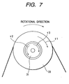
- An external wheel 33 of a one-way clutch is entrained by a crank pulley (not shown) via a belt.
- a clutch portion comprising sprag and roller members and a spring member (which are not shown), selectively engages or disengages an internal wheel 31 and the external wheel 33.
- a driving torque ⁇ 1 of the internal combustion engine acts on the external wheel 33.
- a driving torque ⁇ 2 of the automotive alternator which is referred to as power generation torque, acts on the internal wheel 31 in a direction opposed to the engine driving torque ⁇ 1.
- inertial of an alternator rotor causes an inertial torque ⁇ 3 which also acts on the internal wheel 31.
- the inertial torque ⁇ 3 changes its direction in accordance with change of rotation of the internal wheel 31.
- the direction of the inertial torque ⁇ 3 is identical with that of the alternator driving torque ⁇ 2 when the rotational speed of the internal wheel 31 is increasing and is opposed when decreasing.
- Engagement and disengagement of the one-way clutch is designed so as to be determined according to the large and small relationship among these three torques.
- the directions of torques ⁇ 1, ⁇ 2, and ⁇ 3 shown in Fig. 7 are now assumed to be positive, while ⁇ 1 represents the rotational speed of the internal wheel 31 and ⁇ 2 represents the rotational speed of the external wheel 33.
- the torque ⁇ 1 decreases correspondingly.
- the inertial torque ⁇ 3 of the automotive alternator will exceed the engine driving torques ⁇ 1 which acts in the same direction as that of the inertial torque ⁇ 3.
- the above condition ⁇ 1 ⁇ ⁇ 3 - ⁇ 2 is established.
- the one-way clutch is disengaged.
- the power generation torque ⁇ 2 is larger than the inertia torque ⁇ 3 during the disengaged state of the one-way clutch. Therefore, the rotational speed of the alternator rotor decreases quickly and the one-way clutch is again engaged within a short period of time after the one-way clutch is once disengaged, even when the engine speed is decreasing or in the very beginning of acceleration from its lowest rotational speed (where the increasing rate of the rotational speed is small).
- the above-described conventional automotive alternator cannot bring satisfactory effect, although the one-way clutch is intentionally provided to release the internal combustion engine from the load torque of the automotive alternator when the internal combustion engine is decreasing.
- the present invention has an object to provide an alternating-current generating apparatus for an automotive vehicle which is capable of adequately suppressing the fluctuation of engine speed without increasing the size and weight of a one-way clutch equipped automotive alternator installed on an internal combustion engine.
- the present invention solves the following problems.
- the rotational speed of the automotive alternator i.e., the rotational speed of the internal wheel of the clutch
- the one-way clutch is re-engaged so as to increase the load torque of the internal combustion engine.
- This will induce undesirable reduction of rotational speed during the deceleration period of the internal combustion engine and will obstruct the buildup of acceleration in the very beginning of the acceleration period or in a situation where the acceleration rate is small.
- the internal combustion engine suffers from large fluctuation appearing in the rotational speed. Such undesirable fluctuation of engine speed gives adverse influence to the engine control.
- the field of the alternator can be controlled in accordance with the engaged/disengaged state of the clutch so that the engine can be maintained in adequate conditions for the control.
- the one-way clutch comprises a power input section for receiving a driving power from the internal combustion engine and a power output section mechanically connected to a rotor of the automotive alternator which has a plurality of filed poles.
- the detecting means detects a rotational speed of the power output section based on a frequency component of an output voltage of a multiphase armature winding of the automotive alternator.
- control means compares the rotational speed of the power output section with a rotational speed of the power input section and judges that the one-way clutch is in the engaged state when the rotational speed of the power output section is equal to the rotational speed of the power input section and judges that the one-way clutch is in the disengaged state when the rotational speed of the power output section is not equal to the rotational speed of the power input section.
- This arrangement makes it possible to discriminate the engaged state and the disengaged state of the clutch by using a simple comparing circuit and well-known F-V convertors.
- the one-way clutch comprises an external wheel portion constituting the power input section, an internal wheel portion disposed coaxially with the external wheel portion and constituting the power output section, and a clutch portion selectively engaging or disengaging the external wheel portion and the internal wheel portion.
- This arrangement makes it possible to easily receive the driving power of the internal combustion engine by forming a pulley or gear portion on an outer periphery of the external wheel portion, thereby realizing an extremely compact clutch device for the automotive alternator.
- the automotive alternator has a field winding
- the control means is associated with switching means connected in series with the field winding for on-off controlling power current supply to the field winding.
- the control means closes the switching means when the one-way clutch is in the engaged state and opens the switching means when the one-way clutch is in the disengaged state.
- This arrangement makes it possible to surely realize desired operations. More specifically, when the one-way clutch is in the engaged condition, the exciting current of the filed winding is increased so as to increase the electric power generation torque, thereby suppressing the rotational speed of the internal combustion from rapidly increasing. When the one-way clutch is in the disengaged condition, the exciting current of the filed winding is decreased so as to decrease the electric power generation torque, thereby suppressing the rotational speed of the internal combustion from rapidly decreasing.
- an electric signal discriminating the engaged state and the disengaged state of the one-way clutch serves as an on/off signal of the switching means which controls the supply of the exciting current. This makes it possible to surely synchronize the engagement/disengagement of the one-way clutch with the on/off operation of the switching means. Thus, it becomes possible to instantly suppress the fluctuation of engine speed having an extremely high frequency responsive to the torque variation caused in each stroke of the internal combustion engine, thereby facilitating the engine control and suppressing the vibration.
- Fig. 2 is a partly cross-sectional view showing an automotive alternator 100 in accordance with the first embodiment of the present invention, taken along an axis of this automotive alternator 100.
- the automotive alternator 100 has an armature 1 accommodating a rotor 2 coaxially disposed therein.
- the rotor 2 has field poles 21.
- a field winding 22 is wound around the field poles 21 which are coupled and securely fixed to a rotational shaft 23.
- a one-way clutch has an internal wheel 31 which is fixed to the rotational shaft 23 by means of a nut 32.
- An external wheel 33 of the one-way clutch is entrained by a crank pulley (not shown) via a belt so as to be driven by an engine (not shown).
- the outer peripheral portion of the external wheel 33 serves as a pulley.
- a clutch portion 34 configured into a cylindrical shape, performs torque transmission in only one way from the external wheel 33 to the internal wheel 31. In other words, no torque is transmitted via the clutch portion 34 in the opposite direction from the internal wheel 31 to the external wheel 33.
- a position detector 4 detects a rotational position of the external wheel 33. To adjust an output voltage of the alternator, the field current flowing across the field winding 22 is on-off controlled by a regulator 5.
- a rectifier 6 converts AC power generated by the armature 1 into DC power.
- An output terminal 7 is connected to a positive pole fin of the rectifier 6.
- a rear cover 9 protects these electric components from the surrounding environment.
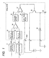
- the regulator 5 detects an instantaneous value (analog value) of a mono-phasic voltage 11 of the armature winding 1.
- the armature winding 1 induces an AC voltage in response to rotation of the field poles 21.
- 2p represents the total number of the field poles 21
- Nalt(rpm) represents a mechanical rotational speed of the rotor
- a comparator 51 compares the mono-phasic voltage 11 of the armature winding 1 with an appropriate threshold for binarization and produces a rectangular wave pulse signal having the above-described frequency.
- a first F-V converter 52 receives the rectangular wave pulse signal produced from the comparator 51 and produces a DC voltage whose magnitude is proportional to the rotational speed of the rotor 2. The magnitude of this DC voltage represents a rotational speed ⁇ 1 of the internal wheel 31 (i.e., the rotor 2).
- a position detector 4 provided in the vicinity of the external wheel 33, generates a rectangular wave pulse signal whose frequency is proportional to the rotational speed of the external wheel 33.
- a second F-V converter 53 receives the rectangular wave pulse signal produced from the position detector 4 and produces a DC voltage whose magnitude is proportional to the rotational speed of the external wheel 33. The magnitude of this DC voltage represents a rotational speed ⁇ 2 of the external wheel 33.
- the position detector 4 of this embodiment is, for example, a conventional rotation speed detector, such as a photoelectric sensor or a semiconductor sensor. Alternatively, the position detector 4 can be omitted when the rotational speed ⁇ 2 of the external wheel 33 is calculated based on the engine speed and a pulley ratio between the crank pulley and the external wheel 33.
- a comparator 54 of the regulator 5 compares two DC voltages representing the rotational speeds ⁇ 1 and ⁇ 2, respectively.
- a voltage setter 55 is provided to set a regulated voltage Vreg for the idling condition where the rotational speeds ⁇ 2 of the external wheel 33 is not larger than a predetermined value.
- the voltage setter 55 adjusts the regulated voltage Vreg to a second set value, e.g., 12.5 V, which is lower than the first set value when the one-way clutch is disengaged (i.e., ⁇ 1 > ⁇ 2).
- a battery voltage Vbatt is entered via a low-pass filter 56 into a negative input terminal of a comparator 57.
- a positive input terminal of the comparator 57 receives the regulated voltage Vreg generated from the voltage setter 55.
- the comparator 57 generates an off signal for a transistor 58 when the battery voltage Vbatt is larger than the regulated voltage (i.e., Vbatt > Vreg) and generates an on signal for the transistor 58 when the battery voltage Vbatt is smaller than the regulated voltage (i.e., Vbatt ⁇ Vreg).
- the transistor 58 receives power voltage through a B terminal and controls the field current via an F terminal 60 of the regulator 5.
- a flywheel diode 59 connected to the earth through an E terminal, circulates the field current during the off state of the transistor 58.
- the F terminal 60 is connected to the field winding 22 via the brush 8.
- the battery voltage Vbatt is usually adjustable within a range of 12V to 14V.
- the charging operation continues until the battery voltage Vbatt reaches 14. 5V.
- the power generation is suppressed once the battery voltage Vbatt has reached 12.5V.
- the open terminal voltage of the battery is usually in a range of 12V to 12.5V, the terminal voltage immediately reaches 12.5V.
- the power generation is stopped within a short period of time.
- the power generation amount during the disengaged state of the one-way clutch is reduced compared with the power generation amount during the engaged state.
- the power generation torque ⁇ 2 acting on the internal wheel 31 (which controls the rotation of the alternator) during the disengaged state of the one-way clutch becomes small.
- the reduction of rotational speed of the internal wheel 31 is adequately suppressed.
- the one-way clutch when the one-way clutch is engaged in the beginning of an increasing state of the engine rotational speed, the engine load increases suddenly. This forces the conventional engine to consume a great amount of fuel to return the engine speed to a target value.
- the engagement of the one-way clutch is delayed until the engine speed is almost restored to the target value. Therefore, the first embodiment does not require the engine to consume excessive fuel to quickly return the target speed.
- the internal combustion engine of the present invention is not limited to diesel engines. Therefore, the present invention can be applied to gasoline engines too.
- the power generation control can be performed by linearly changing the setting value for the regulated voltage Vreg or based on the duty ratio control of the field current control transistor 58.
- Fig. 3 shows the difference of operation between the automotive generator in accordance with the first embodiment and a conventional alternator having no one-way clutch.
- the above-described power generation control is performed in synchronism with the one-way clutch operation. Therefore, as shown in Fig. 3, the clutch-off period can be extended.
- the free term during which the engine is released from the load of the alternator can be extended.
- the first embodiment promptly responds to such suppression.
- the first embodiment concentrates the clutch-on period so as to agree with the peak period of the engine torque. This is effective to reduce the fluctuation of engine torque.
- the second embodiment is similar to the above-described first embodiment in that the regulated voltage Vreg is set to a higher value, e.g., 15.5V, at the moment the one-way clutch is engaged or immediately after that. But the second embodiment is characterized in that the set value for the regulated voltage Vreg is gradually reduced with elapsed time.
- the automotive alternator 100 performs full generation of electric power at the moment the one-way clutch is engaged or immediately after that. In this condition, a maximized braking torque acts on the engine so as to adequately suppress the increase of engine speed.
- the second embodiment gradually reduces the set value of the regulated voltage Vreg during the engaged state of the one-way clutch. This is effective to prevent the battery from being excessively charged. Accordingly, the life of battery can be extended.
- the second embodiment suppresses the power generation during the clutch-off period.
- the engine control apparatus can promptly return the engine speed to a target value. More specifically, the engine has a large inertia and tends to cause an overshoot after reaching a target speed when it is accelerated sufficiently.
- the second embodiment immediately increases the power generation amount of the alternator at the moment the one-way clutch is engaged (i.e., at the moment the engine speed is almost restored the target speed) so as to enhance the engine braking torque.
- the second embodiment immediately increases the power generation amount of the alternator at the moment the one-way clutch is engaged (i.e., at the moment the engine speed is almost restored the target speed) so as to enhance the engine braking torque.
- Fig. 8 shows a circuit arrangement of a voltage setter in accordance with the second embodiment.
- Fig. 9 is a timing chart showing signal changes in the voltage setter shown in Fig. 8.
- a voltage setter 551 corresponds to the voltage setter 55 shown in Fig. 1 and therefore has the same input/output relationship as that shown in Fig. 1.
- a resistor 5517 and a capacitor 5518 cooperatively constitute a filter for gradually changing the regulated voltage Vreg from the first reference value Vreg1 ( ⁇ 15.5V) to the second reference value Vreg2 ( ⁇ 14.5V).
- R7 represents the resistance value of resistor 5517
- C1 represents the capacitance value of capacitor 5518
- the regulated voltage Vreg changes with a time constant C1 ⁇ R7.
- An inverter 5519 generates an inversed output of the comparator 54 which serves as a gate drive signal for a switch 5521.
- a switch 5520 generates the regulated voltage Vreg which gradually reduces from the first reference value Vreg1 ( ⁇ 15.5V) to the second reference value Vreg2 ( ⁇ 14.5V).
- a switch 5521 whose operation is in exclusive relationship with that of the switch 5520, generates the regulated voltage Vreg which is equal to the third reference value Vreg3 ( ⁇ 12.5V).
- An output line 5522 generates an output signal of the voltage setter 551. This output signal is supplied to the comparator 57.
- the input terminal 5510 receives a Hi-level signal.
- the switches 5520 and 5523 turn on, while the switch 5521 turns off.
- the regulated voltage Vreg is once set to the higher voltage Vreg1 ( ⁇ 15.5V). After that, due to function of the filter, the regulated voltage Vreg gradually decreases to the level of the second reference value Vreg2 ( ⁇ 14.5V) with elapsed time.
- the regulated voltage Vreg is set to the constant level of the third reference value Vreg3 ( ⁇ 12.5V) so as to suppress the power generation.
- the rotational speed of the internal wheel 31 i.e., the rotor of the alternator
- the rotational speed of the internal wheel 31 decreases after the one-way clutch is disengaged.
- the mono-phasic voltage of the internal wheel 31 obtained from the P terminal is processed through the comparator 51 and the F-V converter 52 in the same manner as disclosed in Fig. 1 to obtain a DC voltage whose magnitude is proportional to the rotational speed ⁇ 1 of the internal wheel 31.
- a differentiating circuit 501 produces a differential signal of the DC voltage outputted from the F-V converter 52.
- a comparator 502 connected to an output terminal of the differentiating circuit 501, judges that the one-way clutch is in the disengaged state when the sign of the differential signal is minus.
- a switching circuit 61 switches the regulated voltage Vreg.
- the switching circuit 61 supplies a regulated voltage Vreg having a small value Vreg3 ( ⁇ 12.5V) to the comparator 57.
- the switching circuit 61 supplies a regulated voltage Vreg having a large value Vreg2 ( ⁇ 14.5V) to the comparator 57.
- the position detector 4 for the external wheel 33 can be omitted.
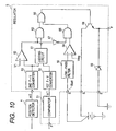
- the fourth embodiment comprises the comparator 51, the first F-V converter 52, the second F-V converter 53, the low-pass filter 56, the power transistor 58, and the flywheel diode 59 which are structurally and functionally identical with those of the first embodiment disclosed in Fig. 1.
- a judging circuit 61 judges whether or not the rotational speed ⁇ 2 of the external wheel 33 is equal to the internal speed ⁇ 1 of the internal wheel 31.
- a comparator 62 judges whether or not the rotational speed ⁇ 2 of the external wheel 33 is equal to or larger than a predetermined value.
- An AND gate 63 produces the output signal of the judging circuit 61 in response to the output of the comparator 62. More specifically, when the rotational speed ⁇ 2 of the external wheel 33 becomes smaller than the predetermined value, the comparator 62 produces a Hi-level signal.
- the output of the judging circuit 61 is supplied to the power transistor 58 via an OR circuit 66.
- a comparator 64 compares the battery voltage Vbatt with a predetermined regulated voltage Vreg.
- An AND gate 65 produces the output signal of the comparator 64 in response to an output of an inverter 67. More specifically, when the rotational speed ⁇ 2 of the external wheel 33 becomes smaller than the predetermined value, the inverter 67 produces a Lo-level signal. Thus, the output of the comparator 64 is not supplied to the power transistor 58 via the OR circuit 66.
- the OR circuit 66 functions as a means for calculating a logical sum of the outputs of two AND gates 63 and 65. In response to the output signal of the OR gate 66, the power transistor 58 turns on or off the field current.
- the above-described fourth embodiment operates in the following manner.
- the comparator 62 supplies a Hi-level signal to the AND gate 63 so as to validate the output transmission of the judging circuit 61. Meanwhile, the inverter 67 supplies a Lo-level signal to the AND gate 65 to invalidate the output transmission of the comparator 64.
- the predetermined value e.g., idling speed of the engine
- the on/off control of power transistor 58 is solely dependent on the engaged/disengaged state of the one-way clutch.
- the comparator 62 When the rotational speed exceeds the predetermined value, the comparator 62 produces a Lo-level signal so as to invalidate the output of the judging circuit 61.
- the on/off control of power transistor 58 is solely dependent on the comparison result between the battery voltage Vbatt and the regulated voltage Vreg, considering the situation that the engine speed has increased to a sufficiently high level. In other words, the rotational fluctuation induced by engagement/disengagement of the one-way clutch is no longer troublesome in the sufficiently high engine speed condition and is therefore negligible. The control should be rather performed considering the excessive charging of the battery caused when the power generation ability is increased.
- the power transistor 58 turns off when the battery voltage Vbatt exceeds the predetermined regulated voltage Vreg and turns on when the battery voltage Vbatt becomes smaller than the predetermined regulated voltage Vreg.
- the fourth embodiment easily prevents the battery from being excessively charged.
Description
Claims (4)
- An alternating-current generating apparatus for an automotive vehicle comprising:characterized in thata clutch (31, 33, 34);an automotive alternator (100) driven by an internal combustion engine;control means (5) for controlling a power generation amount of said automotive alternator,detecting means provided for detecting a rotational speed of either said internal combustion engine or said automotive alternator (100) as well as an electric amount relating to an on-off state of said clutch (31, 33, 34),said control means (5) performs at least one of two power controls when said internal combustion engine is in a low-rotational operating condition, one of said two power controls is to increase the power generation amount during an engaged state of said clutch (31, 33, 34) and the other of said two power controls is to decrease the power generation amount during a disengaged state of said clutch (31, 33, 34),a) said clutch (31, 33, 34) is a one-way clutch;b) said automotive alternator (100) is driven by said internal combustion engine via said one-way clutch (31, 33, 34); andc) said control means is formed for increasing the excitation current of the field winding when the one-way clutch (31, 33, 34) is in the engaged condition so as to increase the electric power generation torque, and for decreasing the excitation current of the field winding when the one-way clutch (31, 33, 34) is in the disengaged condition so as to decrease the electric power generation torque.
- The alternating-current generating apparatus for an automotive vehicle in accordance with claim 1, whereinsaid one-way clutch comprises a power input section (33) for receiving a driving power from said internal combustion engine and a power output section (31) mechanically connected to a rotor (2) of said automotive alternator which has a plurality of filed poles (21);said detecting means detects a rotational speed of said power output section based on a frequency component of an output voltage of a multiphase armature winding (1) of said automotive alternator; andsaid control means compares the rotational speed of said power output section (31) with a rotational speed of said power input section (33) and judges that said one-way clutch is in the engaged state when said rotational speed of said power output section is equal to the rotational speed of said power input section and judges that said one-way clutch is in the disengaged state when said rotational speed of said power output section is not equal to the rotational speed of said power input section.
- The alternating-current generating apparatus for an automotive vehicle in accordance with claim 2, wherein
said one-way clutch comprises an external wheel portion (33) constituting said power input section, an internal wheel portion (31) disposed coaxially with said external wheel portion and constituting said power output section, and a clutch portion (34) selectively engaging or disengaging said external wheel portion and said internal wheel portion. - The alternating-current generating apparatus for an automotive vehicle in accordance with any one of claims 1 to 3, wherein
said automotive alternator has a field winding (22), and
said control means is associated with switching means (58) connected in series with said field winding for on-off controlling power current supply to said field winding,
wherein said control means closes said switching means when said one-way clutch is in the engaged state and opens said switching means when said one-way clutch is in the disengaged state.
Applications Claiming Priority (4)
| Application Number | Priority Date | Filing Date | Title |
|---|---|---|---|
| JP2000072914 | 2000-03-15 | ||
| JP2000072914 | 2000-03-15 | ||
| JP2000316461 | 2000-10-17 | ||
| JP2000316461A JP4154848B2 (en) | 2000-03-15 | 2000-10-17 | AC generator for vehicle |
Publications (3)
| Publication Number | Publication Date |
|---|---|
| EP1137165A2 EP1137165A2 (en) | 2001-09-26 |
| EP1137165A3 EP1137165A3 (en) | 2002-10-09 |
| EP1137165B1 true EP1137165B1 (en) | 2005-12-14 |
Family
ID=26587615
Family Applications (1)
| Application Number | Title | Priority Date | Filing Date |
|---|---|---|---|
| EP01106162A Expired - Lifetime EP1137165B1 (en) | 2000-03-15 | 2001-03-13 | Alternating-current generating apparatus for an automotive vehicle |
Country Status (4)
| Country | Link |
|---|---|
| US (1) | US6455946B2 (en) |
| EP (1) | EP1137165B1 (en) |
| JP (1) | JP4154848B2 (en) |
| DE (1) | DE60115747T2 (en) |
Cited By (1)
| Publication number | Priority date | Publication date | Assignee | Title |
|---|---|---|---|---|
| US8362487B2 (en) | 2002-06-11 | 2013-01-29 | Semiconductor Energy Laboratory Co., Ltd. | Light emitting device comprising film having hygroscopic property and transparency |
Families Citing this family (7)
| Publication number | Priority date | Publication date | Assignee | Title |
|---|---|---|---|---|
| JP4000863B2 (en) * | 2002-02-15 | 2007-10-31 | 株式会社デンソー | Vehicle power generation system |
| JP3826822B2 (en) * | 2002-03-20 | 2006-09-27 | 株式会社デンソー | Vehicle power generation control device |
| JP4670720B2 (en) | 2006-04-21 | 2011-04-13 | 株式会社デンソー | Vehicle power generation control device |
| JP4556937B2 (en) | 2006-10-11 | 2010-10-06 | 株式会社デンソー | Generator control system |
| JP2009261084A (en) * | 2008-04-15 | 2009-11-05 | Yamaha Motor Electronics Co Ltd | Engine idling stabilizer |
| US8536725B2 (en) * | 2010-02-27 | 2013-09-17 | Mehboob Lakhani | Compact wind and water turbine systems |
| DE102016216519A1 (en) * | 2016-09-01 | 2018-03-01 | Robert Bosch Gmbh | Determining a clutch state of a coupled to a clutch to an internal combustion engine drive train of a motor vehicle |
Family Cites Families (14)
| Publication number | Priority date | Publication date | Assignee | Title |
|---|---|---|---|---|
| JPH0772585B2 (en) | 1985-03-29 | 1995-08-02 | バンドー化学株式会社 | Belt transmission for engine accessories |
| US5270575A (en) * | 1989-11-30 | 1993-12-14 | Mitsubishi Jidosha Kogyo Kabushiki Kaisha | Device for controlling change in idling |
| JP2528995B2 (en) * | 1990-03-19 | 1996-08-28 | 株式会社日立製作所 | In-vehicle generator control system |
| JPH0772585A (en) | 1993-07-06 | 1995-03-17 | Fuji Photo Film Co Ltd | Polyester substrate |
| US5402007A (en) * | 1993-11-04 | 1995-03-28 | General Motors Corporation | Method and apparatus for maintaining vehicle battery state-of-change |
| JPH08140308A (en) | 1994-11-10 | 1996-05-31 | Mitsubishi Electric Corp | Charging generator for vehicle |
| JPH08317599A (en) * | 1995-05-22 | 1996-11-29 | Mitsubishi Electric Corp | Generator for vehicle |
| JPH0988778A (en) * | 1995-07-17 | 1997-03-31 | Denso Corp | Starter generator |
| JPH09140196A (en) | 1995-11-14 | 1997-05-27 | Denso Corp | Power generation controller for vehicle |
| ATE248300T1 (en) * | 1997-05-07 | 2003-09-15 | Litens Automotive Inc | BELT DRIVE SYSTEM WITH GENERATOR CONNECTION ONE-WAY CLUTCH |
| JP3731702B2 (en) * | 1997-09-24 | 2006-01-05 | 光洋精工株式会社 | Pulley unit |
| JP3785259B2 (en) * | 1997-09-25 | 2006-06-14 | 株式会社ジェイテクト | Pulley unit |
| JP2000240461A (en) * | 1999-02-23 | 2000-09-05 | Nsk Ltd | One-way clutch built-in type pulley device for alternator and method for preventing creak of alternator driving endless belt |
| JP2001014135A (en) * | 1999-06-29 | 2001-01-19 | Seiko Epson Corp | Presentation system, presentation method and information storage medium |
-
2000
- 2000-10-17 JP JP2000316461A patent/JP4154848B2/en not_active Expired - Fee Related
-
2001
- 2001-03-13 DE DE60115747T patent/DE60115747T2/en not_active Expired - Lifetime
- 2001-03-13 EP EP01106162A patent/EP1137165B1/en not_active Expired - Lifetime
- 2001-03-15 US US09/808,364 patent/US6455946B2/en not_active Expired - Fee Related
Cited By (1)
| Publication number | Priority date | Publication date | Assignee | Title |
|---|---|---|---|---|
| US8362487B2 (en) | 2002-06-11 | 2013-01-29 | Semiconductor Energy Laboratory Co., Ltd. | Light emitting device comprising film having hygroscopic property and transparency |
Also Published As
| Publication number | Publication date |
|---|---|
| US20010022449A1 (en) | 2001-09-20 |
| JP4154848B2 (en) | 2008-09-24 |
| US6455946B2 (en) | 2002-09-24 |
| DE60115747T2 (en) | 2006-10-05 |
| JP2001333599A (en) | 2001-11-30 |
| EP1137165A3 (en) | 2002-10-09 |
| DE60115747D1 (en) | 2006-01-19 |
| EP1137165A2 (en) | 2001-09-26 |
Similar Documents
| Publication | Publication Date | Title |
|---|---|---|
| JP3810345B2 (en) | Transmission control device for vehicle | |
| US6109237A (en) | Apparatus for controlling the idling speed of an internal combustion engine | |
| US7528585B2 (en) | Vehicle-use power generation control apparatus | |
| US5033425A (en) | Internal combustion engine equipped with a torque controller | |
| US20040164560A1 (en) | Transmission gear apparatus for motor vehicle | |
| JP3982247B2 (en) | Control device for vehicle generator | |
| EP1137165B1 (en) | Alternating-current generating apparatus for an automotive vehicle | |
| US4662496A (en) | System for controlling the clutch torque of an electromagnetic clutch for vehicles | |
| GB2114707A (en) | Variable capacity flywheel | |
| JP4270445B2 (en) | Output generator for synchronous generator | |
| US5266836A (en) | Method and apparatus for operating a motor vehicle alternator | |
| US20030015927A1 (en) | Vehicle AC generator | |
| US20040067803A1 (en) | Belt-drive system driven by internal combustion engine mounted on automotive vehicle | |
| JP3938747B2 (en) | Output generator for synchronous generator | |
| JP3258055B2 (en) | Alternator power generation controller | |
| JP4973639B2 (en) | Charge control device and charge control system | |
| JPS6035926A (en) | Controller of automotive generator | |
| JP3517981B2 (en) | Idle speed control device | |
| JP3004296B2 (en) | Control device for vehicle alternator | |
| JP4947033B2 (en) | Vehicle power generation control device and vehicle power generation control system | |
| JP3028867B2 (en) | Alternator power generation controller | |
| EP0652626A1 (en) | An electrical generator assembly | |
| JPH0588157U (en) | Alternator power generation control device | |
| US6371887B1 (en) | Electrical power drive device | |
| JPH0213792Y2 (en) |
Legal Events
| Date | Code | Title | Description |
|---|---|---|---|
| PUAI | Public reference made under article 153(3) epc to a published international application that has entered the european phase |
Free format text: ORIGINAL CODE: 0009012 |
|
| AK | Designated contracting states |
Kind code of ref document: A2 Designated state(s): AT BE CH CY DE DK ES FI FR GB GR IE IT LI LU MC NL PT SE TR |
|
| AX | Request for extension of the european patent |
Free format text: AL;LT;LV;MK;RO;SI |
|
| PUAL | Search report despatched |
Free format text: ORIGINAL CODE: 0009013 |
|
| AK | Designated contracting states |
Kind code of ref document: A3 Designated state(s): AT BE CH CY DE DK ES FI FR GB GR IE IT LI LU MC NL PT SE TR |
|
| AX | Request for extension of the european patent |
Free format text: AL;LT;LV;MK;RO;SI |
|
| RIC1 | Information provided on ipc code assigned before grant |
Free format text: 7H 02P 9/30 A, 7H 02P 9/04 B |
|
| 17P | Request for examination filed |
Effective date: 20021029 |
|
| AKX | Designation fees paid |
Designated state(s): DE FR GB IT |
|
| 17Q | First examination report despatched |
Effective date: 20030811 |
|
| GRAP | Despatch of communication of intention to grant a patent |
Free format text: ORIGINAL CODE: EPIDOSNIGR1 |
|
| RTI1 | Title (correction) |
Free format text: ALTERNATING-CURRENT GENERATING APPARATUS FOR AN AUTOMOTIVE VEHICLE |
|
| GRAS | Grant fee paid |
Free format text: ORIGINAL CODE: EPIDOSNIGR3 |
|
| GRAA | (expected) grant |
Free format text: ORIGINAL CODE: 0009210 |
|
| RIN1 | Information on inventor provided before grant (corrected) |
Inventor name: TANIGUCHI, MAKOTO,C/O DENSO CORPORATION INT.PR.D. |
|
| AK | Designated contracting states |
Kind code of ref document: B1 Designated state(s): DE FR GB IT |
|
| REG | Reference to a national code |
Ref country code: GB Ref legal event code: FG4D |
|
| REF | Corresponds to: |
Ref document number: 60115747 Country of ref document: DE Date of ref document: 20060119 Kind code of ref document: P |
|
| ET | Fr: translation filed | ||
| REG | Reference to a national code |
Ref country code: GB Ref legal event code: 746 Effective date: 20060906 |
|
| PLBE | No opposition filed within time limit |
Free format text: ORIGINAL CODE: 0009261 |
|
| STAA | Information on the status of an ep patent application or granted ep patent |
Free format text: STATUS: NO OPPOSITION FILED WITHIN TIME LIMIT |
|
| 26N | No opposition filed |
Effective date: 20060915 |
|
| PGFP | Annual fee paid to national office [announced via postgrant information from national office to epo] |
Ref country code: GB Payment date: 20130313 Year of fee payment: 13 |
|
| PGFP | Annual fee paid to national office [announced via postgrant information from national office to epo] |
Ref country code: IT Payment date: 20130312 Year of fee payment: 13 |
|
| GBPC | Gb: european patent ceased through non-payment of renewal fee |
Effective date: 20140313 |
|
| PG25 | Lapsed in a contracting state [announced via postgrant information from national office to epo] |
Ref country code: GB Free format text: LAPSE BECAUSE OF NON-PAYMENT OF DUE FEES Effective date: 20140313 |
|
| PG25 | Lapsed in a contracting state [announced via postgrant information from national office to epo] |
Ref country code: IT Free format text: LAPSE BECAUSE OF NON-PAYMENT OF DUE FEES Effective date: 20140313 |
|
| REG | Reference to a national code |
Ref country code: FR Ref legal event code: PLFP Year of fee payment: 16 |
|
| PGFP | Annual fee paid to national office [announced via postgrant information from national office to epo] |
Ref country code: FR Payment date: 20160321 Year of fee payment: 16 |
|
| PGFP | Annual fee paid to national office [announced via postgrant information from national office to epo] |
Ref country code: DE Payment date: 20160330 Year of fee payment: 16 |
|
| REG | Reference to a national code |
Ref country code: DE Ref legal event code: R119 Ref document number: 60115747 Country of ref document: DE |
|
| REG | Reference to a national code |
Ref country code: FR Ref legal event code: ST Effective date: 20171130 |
|
| PG25 | Lapsed in a contracting state [announced via postgrant information from national office to epo] |
Ref country code: FR Free format text: LAPSE BECAUSE OF NON-PAYMENT OF DUE FEES Effective date: 20170331 Ref country code: DE Free format text: LAPSE BECAUSE OF NON-PAYMENT OF DUE FEES Effective date: 20171003 |