EP1138263A2 - Graft fixation device - Google Patents
Graft fixation device Download PDFInfo
- Publication number
- EP1138263A2 EP1138263A2 EP01302831A EP01302831A EP1138263A2 EP 1138263 A2 EP1138263 A2 EP 1138263A2 EP 01302831 A EP01302831 A EP 01302831A EP 01302831 A EP01302831 A EP 01302831A EP 1138263 A2 EP1138263 A2 EP 1138263A2
- Authority
- EP
- European Patent Office
- Prior art keywords
- implantation
- distal end
- members
- proximal
- distal
- Prior art date
- Legal status (The legal status is an assumption and is not a legal conclusion. Google has not performed a legal analysis and makes no representation as to the accuracy of the status listed.)
- Granted
Links
Images


Classifications
-
- A—HUMAN NECESSITIES
- A61—MEDICAL OR VETERINARY SCIENCE; HYGIENE
- A61B—DIAGNOSIS; SURGERY; IDENTIFICATION
- A61B17/00—Surgical instruments, devices or methods, e.g. tourniquets
- A61B17/068—Surgical staplers, e.g. containing multiple staples or clamps
-
- A—HUMAN NECESSITIES
- A61—MEDICAL OR VETERINARY SCIENCE; HYGIENE
- A61B—DIAGNOSIS; SURGERY; IDENTIFICATION
- A61B17/00—Surgical instruments, devices or methods, e.g. tourniquets
- A61B17/064—Surgical staples, i.e. penetrating the tissue
- A61B17/0642—Surgical staples, i.e. penetrating the tissue for bones, e.g. for osteosynthesis or connecting tendon to bone
-
- A—HUMAN NECESSITIES
- A61—MEDICAL OR VETERINARY SCIENCE; HYGIENE
- A61B—DIAGNOSIS; SURGERY; IDENTIFICATION
- A61B17/00—Surgical instruments, devices or methods, e.g. tourniquets
- A61B17/56—Surgical instruments or methods for treatment of bones or joints; Devices specially adapted therefor
- A61B17/58—Surgical instruments or methods for treatment of bones or joints; Devices specially adapted therefor for osteosynthesis, e.g. bone plates, screws, setting implements or the like
- A61B17/88—Osteosynthesis instruments; Methods or means for implanting or extracting internal or external fixation devices
- A61B17/92—Impactors or extractors, e.g. for removing intramedullary devices
-
- A—HUMAN NECESSITIES
- A61—MEDICAL OR VETERINARY SCIENCE; HYGIENE
- A61B—DIAGNOSIS; SURGERY; IDENTIFICATION
- A61B17/00—Surgical instruments, devices or methods, e.g. tourniquets
- A61B17/064—Surgical staples, i.e. penetrating the tissue
- A61B2017/0647—Surgical staples, i.e. penetrating the tissue having one single leg, e.g. tacks
-
- A—HUMAN NECESSITIES
- A61—MEDICAL OR VETERINARY SCIENCE; HYGIENE
- A61F—FILTERS IMPLANTABLE INTO BLOOD VESSELS; PROSTHESES; DEVICES PROVIDING PATENCY TO, OR PREVENTING COLLAPSING OF, TUBULAR STRUCTURES OF THE BODY, e.g. STENTS; ORTHOPAEDIC, NURSING OR CONTRACEPTIVE DEVICES; FOMENTATION; TREATMENT OR PROTECTION OF EYES OR EARS; BANDAGES, DRESSINGS OR ABSORBENT PADS; FIRST-AID KITS
- A61F2/00—Filters implantable into blood vessels; Prostheses, i.e. artificial substitutes or replacements for parts of the body; Appliances for connecting them with the body; Devices providing patency to, or preventing collapsing of, tubular structures of the body, e.g. stents
- A61F2/0063—Implantable repair or support meshes, e.g. hernia meshes
-
- A—HUMAN NECESSITIES
- A61—MEDICAL OR VETERINARY SCIENCE; HYGIENE
- A61F—FILTERS IMPLANTABLE INTO BLOOD VESSELS; PROSTHESES; DEVICES PROVIDING PATENCY TO, OR PREVENTING COLLAPSING OF, TUBULAR STRUCTURES OF THE BODY, e.g. STENTS; ORTHOPAEDIC, NURSING OR CONTRACEPTIVE DEVICES; FOMENTATION; TREATMENT OR PROTECTION OF EYES OR EARS; BANDAGES, DRESSINGS OR ABSORBENT PADS; FIRST-AID KITS
- A61F2/00—Filters implantable into blood vessels; Prostheses, i.e. artificial substitutes or replacements for parts of the body; Appliances for connecting them with the body; Devices providing patency to, or preventing collapsing of, tubular structures of the body, e.g. stents
- A61F2/02—Prostheses implantable into the body
- A61F2/08—Muscles; Tendons; Ligaments
- A61F2/0811—Fixation devices for tendons or ligaments
-
- A—HUMAN NECESSITIES
- A61—MEDICAL OR VETERINARY SCIENCE; HYGIENE
- A61F—FILTERS IMPLANTABLE INTO BLOOD VESSELS; PROSTHESES; DEVICES PROVIDING PATENCY TO, OR PREVENTING COLLAPSING OF, TUBULAR STRUCTURES OF THE BODY, e.g. STENTS; ORTHOPAEDIC, NURSING OR CONTRACEPTIVE DEVICES; FOMENTATION; TREATMENT OR PROTECTION OF EYES OR EARS; BANDAGES, DRESSINGS OR ABSORBENT PADS; FIRST-AID KITS
- A61F2/00—Filters implantable into blood vessels; Prostheses, i.e. artificial substitutes or replacements for parts of the body; Appliances for connecting them with the body; Devices providing patency to, or preventing collapsing of, tubular structures of the body, e.g. stents
- A61F2/02—Prostheses implantable into the body
- A61F2/28—Bones
- A61F2/2846—Support means for bone substitute or for bone graft implants, e.g. membranes or plates for covering bone defects
Definitions
- the field of art to which this invention relates is surgical fastening devices, in particular, surgical fastening devices for fixating tissue grafts to bone.
- the medical technology associated with tissue engineering has advanced at a rapid pace.
- tissue engineering has advanced at a rapid pace.
- cells from the human body for example, chondrocytes and fibrochrondrocytes from the knee joint.
- These autologous cells are then cultured in a laboratory environment on a bio-absorbable matrix.
- the matrix will typically have a shape substantially similar to the tissue section that needs to be replaced.
- the harvested cells will grow on the matrix to form an implantable section of tissue having substantially the same physical configuration as the section of tissue which needs to be replaced in the patient.
- tissue-engineered construct consisting of cells on the matrix (or, alternatively, consisting of a matrix alone without cells) is then affixed to the bone site using conventionally known surgical fasteners including sutures, periosteal coverings, or fibrin glue.
- tissue engineering are many, not the least of which is, for example, that it is now possible to replace cartilage with living cartilage tissue.
- the likelihood of rejection of the tissue implant is minimised since the cartilage tissue which has been grown in-vitro is identical to the autologous cartilage of the patient.
- the graft fixation device has first and second implantation members.
- the members are elongated and preferably have a cylindrical configuration.
- the members also have distal ends, proximal ends, and longitudinal axes. There are longitudinal passages extending through the entire length of each implantation member.
- the members have outer surfaces.
- the implantation members are connected to each other by a member having first and second ends and a central section.
- the member is preferably a rod member. The first end of the rod member extends from the proximal end of the first implantation member and the second end of the rod member extends from the proximal end of the second implantation member.
- the rod member is preferably relatively rigid and may be configured to have a variety of geometric shapes, for example, an inverted "U" shape. However, the rod member may also be flexible.
- the rod member maintains the implantation members at a relatively fixed distance from each other.
- the central section of the rod member is designed to engage a section of a tissue-engineered matrix implant.
- the implantation members have a series of ridges extending out from the outer surfaces of the implantation members to assist in preventing withdrawal from a bone site or other anchoring site after the implantation members are implanted into previously-created bore holes.
- Still yet another aspect of the present invention is a graft fixation device combination which is the combination of a fixation device and an insertion device.
- the fixation device has a first implantation member.
- the implantation member has a longitudinal axis, a proximal end, a distal end, an outer surface, and a longitudinal passage therethrough.
- the fixation device also has a second implantation member.
- the second implantation member has a longitudinal axis, a proximal end, a distal end, an outer surface, and a longitudinal passage therethrough.
- Each implantation member preferably has a proximal annular face on its proximal end surrounding the longitudinal passages.
- the connecting member has a central section, a first end extending from the first implantation member and a second end extending from the second implantation member.
- Each insertion device is a member having a proximal end, a distal tapered end and a longitudinal passage therethrough. The distal end of each implantation member is engageable with the proximal end of an insertion device.
- Another aspect of the present invention is the above described combination wherein an insertion device is mounted to the distal end of one of the, or each of the, implantation members.
- the instrument has a removable distal end housing and removable prongs.
- the instrument has an elongated member having a proximal end, a distal end, a distal end surface, and an outer surface. Outer screw threads extend out from the outer surface about the distal end.
- Inner screw threads extend out from the inner surface of the hollow member.
- a pair of spaced apart prong holes extend through the distal end of the hollow member, said prong holes being in communication with the cavity.
- a retention groove extends into the inner surface of the distal end of the hollow member.
- prongs There are a pair of prongs, said prongs having elongated members having distal ends and proximal ends. In a preferred embodiment, a piercing point extends distally from the distal end of each prong.
- a retention member is mounted to the proximal end of each prong, and the retention member has a proximal surface. The instrument is assembled by inserting the prongs through the prong holes, such that the prongs extend through the prong holes, and the proximal retention members are contained within the retention groove.
- the hollow member is then screwed onto the distal end of the elongated member, by engaging the mating inner threads with the outer threads, and rotating the hollow member until the distal end surface of the elongated member is in engagement with the proximal surfaces of the retention members.
- Still yet another aspect of the present invention is the combination of the insertion instrument as described above and a graft fixation device and/or combination of the present invention.
- Yet another aspect of the present invention is a method of using the graft fixation device of the present invention to affix a matrix containing tissue-engineered tissue to a bone.
- Yet another aspect of the present invention is a method of mounting a first article to a second article, in particular using the previously described device or combination.
- the combination of a graft fixation device and a pair of insertion devices may be provided.
- the fixation device has a first implantation member, said implantation member having a longitudinal axis, a proximal end, a distal end, an outer surface, and a longitudinal passage therethrough.
- the fixation device also has a second implantation member, said second implantation member having a longitudinal axis, a proximal end, a distal end, an outer surface, and a longitudinal passage therethrough.
- proximal annular face on the proximal ends of the first and second implantation members surrounding the proximal opening to the longitudinal passage.
- a connecting member connects the first and second implantation members, the connecting member has a central section, a first end extending from the first implantation member and a second end extending from the second implantation member.
- a pair of insertion devices may also be provided.
- Each insertion device consists of a member having a proximal end, a distal tapered end and a longitudinal passage therethrough. The distal end of each implantation member is engageable with the proximal end of an insertion device and, in use, is in engagement therewith.
- an insertion device is molded into the distal end of each implantation member.
- the combination of the fixation device and the insertion devices is mounted to an insertion instrument having a pair of spaced apart prongs, said prongs having distal ends and distal pointed tips extending therefrom, such that the prongs are contained within the passages of the implantation members and insertion members, and such that the distal tips of the prongs extend beyond the distal ends of the insertion members.
- the distal end of each implantation member is then engaged with the proximal end of each insertion device.
- a matrix is placed upon a bone. Then the implantation members and insertion devices are driven through the matrix into the bone, thereby securing the matrix to the bone.
- Yet another aspect of the present invention is the above-described method, wherein the insertion devices are mounted to the implantation members prior to mounting onto the prongs of the insertion instrument, such that the combination is mounted on the prongs in a single step.
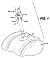
- FIGS. 3-6 illustrate a surgical procedure for affixing a matrix to bone using the graft fixation device of the present invention.
- FIG. 7 is an illustration of a graft fixation device of the present invention after the implantation members have been implanted in bore holes in bone illustrating the device affixing a matrix securely to the surface of a bone.
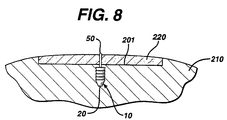
- FIG. 8 is a cross-sectional view of the graft fixation device of FIG. 7 implanted in bone, and taken along View Line 8-8.
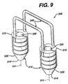
- FIG. 9 is an alternative embodiment of a graft fixation device of the present invention having two connecting members.
- FIG. 10 is a perspective view of an instrument useful for making bore holes in bone into which the implantable members of the graft fixation devices of the present invention may be emplaced.
- FIG. 11 is a perspective view of an instrument useful for implanting the device of the present invention into bore holes made in bone.
- FIG. 12 is a view of a tissue engineered matrix secured to a bone with several graft fixation devices of the present invention.
- FIG. 13 is a perspective view of an alternate embodiment of a graft fixation device of the present invention.
- FIG. 14 is a side view of the graft fixation device of FIG. 13.
- FIG. 15 is an end view of the graft fixation device of FIG. 14.
- FIG. 16 is a cross-sectional view of the graft fixation device of FIG. 14, taken along View-Line 16-16.
- FIG. 17 is a cross-sectional view of the tissue retention member of the graft fixation device of FIG. 14, taken along View-Line 17-17.
- FIG. 18 is a perspective view of an insertion device useful for a graft fixation device of the present invention.
- FIG. 19 is an exploded perspective view of an insertion instrument, a graft fixation device, and two insertion devices.
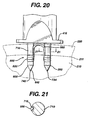
- FIG. 20 is a side view of the distal end of the insertion instrument, a graft fixation device, and insertion devices engaged in bone, prior to removal of the insertion instrument.
- FIG. 21 is a cross-sectional view taken along View-Line 21-21 of FIG. 20 of the prong of the insertion instrument, and a section of the retention member engaged in a longitudinal groove of the prong.
- FIG. 22 is an exploded perspective view of the distal end of an insertion instrument of the present invention, illustrating a removable distal end assembly for creating bore holes in bone for receiving the fixation devices of the present invention, wherein the assembly has an end member and pins.
- FIG. 23 is a cross-section of the assembly end member of FIG. 22, taken along View-Line 23.
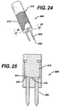
- FIG. 24 is a perspective view of the assembly end of FIG. 22, completely assembled and ready for use.
- FIG. 25 is a cross-sectional view of the end assembly of FIG. 24, taken along View-Line 25-25.
- FIG. 26 is an exploded perspective view of an insertion instrument of the present invention having a removable distal end assembly useful for inserting the graft retention members of the present invention into bore holes in a bone, having an end assembly member and two pins; when used with insertion devices, the instrument can be used to emplace the fixation device directly into bone without first forming bone bore holes.
- FIG. 27 is a cross-sectional view of the end assembly member of FIG. 26.
- FIG. 28 is a perspective view of the distal end of the insertion instrument of FIG. 26, having the end assembly member and prongs fully assembled and mounted.
- FIG. 29 is a cross-sectional view of the distal end of the insertion instrument of FIG. 28 take along View-Line 29-29.
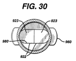
- FIG. 30 is a cross-sectional view of the instrument of FIG. 29 taken along View-Line 30-30.
- FIG. 31 illustrates a fixation device of the present member having an insertion device molded into the distal end of each implantation member.
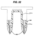
- FIG. 32 is a cross-sectional view of the fixation device of FIG 31.
- the graft fixation devices of the present invention can be made from conventional bio-compatible materials, including absorbable and non-absorbable materials, as well as biodegradable materials.
- the non-absorbable materials which can be utilised include conventional biocompatible materials such as stainless steel, polyethylene, Teflon (RTM), Nitinol (RTM), non-absorbable polymers, other bio-compatible metals, ceramics, combinations thereof and the like.
- the absorbable materials which can be used to manufacture the graft fixation devices of the present invention will typically include those conventional bio-absorbable or bio-resorbable materials known in this art which can be effectively molded or machined.
- the bio-absorbable and bio-resorbable materials include polylactic acid, polydioxanone, polycaprolactone, polyglycolic acid, polygalactic acid, other known biocompatible bio-absorbable and bio-resorbable polymers, ceramics, composites, combinations thereof and the like and equivalents thereof.
- the graft fixation device 10 is seen to have implantation members 20.
- the implantation members 20 are seen to be elongated members, preferably having a substantially cylindrical shape.
- the members 20 may have other geometric shapes including conical, pyramidal, polygonal, cubic, spherical, etc.
- the implantation members 20 are seen to have distal ends 22 and proximal ends 24.
- Each implantation member 20 is seen to have an outer surface 28 and a longitudinal axis 29.
- Each member 20 is also seen to have longitudinal passage 35 extending therethrough.
- the implantation members 20 are also seen to have optional frustoconical ends 30, and proximal endface surfaces 32.
- endface surfaces 32 be flat, endface surface 32 may also be angled, concave, convex, etc.
- Endface surface 32 is seen to have central circular opening 36 in communication with passage 35.
- central opening 36 will have a circular cross-section, but it may have other geometric cross-sections as well including elliptical, polygonal, square, rectangular, combinations thereof and the like.
- Members 20 are also seen to have distal end face surfaces 37 having circular openings 38 in communication with passages 35. As shown with the optional frustoconical end 30, the annular end face surface 37 is of de minimis thickness around opening 38, however this thickness would increase in the absence of a frustoconical end.
- Also seen to extend out from the surface 28 of member 20 are a series of optional projections 40 having tissue engagement edges 44. Without the projections 40, the surface 28 of the member 20 will be smooth.
- the device 10 is seen to have graft retention member 50 connecting the implantation members 20.
- Retention member 50 is seen to be a rod-like member having first end 52, second end 54 and central section 55.
- First end 52 is seen to extend from proximal endface surface 32 of the first member 20 while end 54 is seen to extend up from the proximal endface surface 32 of the other member 20.
- the ends 54 and 52 of retention member 50 may also if desired extend from or be mounted to any section of outer surface 28.
- the connecting member 50 is seen to be preferably bent or shaped into three segments including top segment 55 and leg segments 56.
- the top segment 55 is seen to be substantially perpendicular to the leg segments 56.
- connecting member 50 may have other geometric configurations including semicircular, arced, curved, triangular, polygonal, V-shaped, and the like and combinations thereof.
- the ends 52 and 54 of connecting member 50 may be permanently affixed to the implantation members 20, or may be removably attached thereto in a conventional manner.
- Member 50 may be rigid or flexible. Member 50 will have a sufficient surface area to effectively retain a tissue-engineered matrix in place on a bone or other body surface.
- connecting member 50 will have a circular cross section, but may have other geometric cross-sections as well including elliptical, polygonal, square, rectangular, combinations thereof and the like.
- Member 50 may be rigid or flexible, and may have a single filamentary structure or have multiple interconnected filaments or members.
- FIGS. 3-8 the use of the graft fixation devices 10 of the present invention in a surgical procedure is illustrated.
- the initial step prior to the installation of a matrix containing a tissue-engineered tissue using a graft fixation device 10 of the present invention, is to drill or "tap" two bore holes 200 into a bone 210, for example, subchondral bone in the knee joint.
- the bore holes 200 are seen to be cylindrical holes having a bottom 208 and an open top 202 and side walls 205.
- the bore holes may be bone tunnels with a continuous passage and no bottom, or an open bottom. It is particularly preferred to tap the holes in the bone by using an instrument 400 as illustrated in FIG. 10 which has a proximal section conventionally referred to in this art as a "slap hammer" section.
- tapping or “tap” as used herein is defined to mean a procedure wherein the distal pointed prongs 420 extending from the distal end 415 of the shaft 405 of instrument 400 are located over a bone site, and the proximal end 410 of instrument 400 is tapped or hit with slidable hammer handle 450 (of the "slap hammer"), which slides on shaft 460 between proximal end 410 and proximal stop 470, to form the bone bore holes 200.
- the distal end 465 of shaft 460 is connected to proximal end 410.
- Proximal stop 470 is mounted to proximal end 467.
- Hammer handle 450 is seen to have grasping section 451, collars 455 and longitudinal passage 457.
- a similar pointed instrument may be used to "tap" in the bore holes into bone, that is, any instrument having a nail-like distal end.
- one bone bore hole at a time may be “tapped” in. If the surgeon decides to drill the bore holes into bone, any conventional surgical drilling apparatus may be used. After the bore holes 200 are formed into the bone 210, the matrix 220 containing tissue-engineering tissue is placed upon the bone surface 201 by the surgeon as seen in FIG. 4.
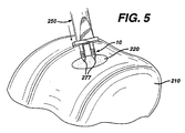
- the graft fixation device 10 is mounted on to the insertion instrument 250.
- Insertion instrument 250 is seen to be an elongated rod 260 having a proximal end 262 and a distal end 264. Mounted to the distal end 264 of the rod 260 is the depth stop 290.
- the depth stop 290 is seen to be a substantially rectangular member which is mounted perpendicular to the longitudinal axis 251 of the rod 260 (see Figure 7). Depth stop 290 is seen to have bottom 292. Extending distally from the bottom 292 of plate member 290 is a pair of parallel, spaced-apart, mounting prongs 270.
- the mounting prongs 270 are seen to be substantially rod-like members having distal pointed tips 277 and proximal ends 272.
- the prongs 270 are seen to have first section 273 and distal section 275.
- Section 273 is seen to have a greater cross-sectional dimension than distal section 275 such that the entire section 275 is insertable into passages 35 of members 20, while proximal section 273 is not insertable therein.
- Instrument 250 is also seen to have a "slap hammer section” consisting of proximal shaft 300 extending from proximal end 262, slidable hammer handle 320 (the “slap hammer") which is slidable upon shaft 300 between proximal end 262, and proximal stop 330.
- Hammer handle member 320 is seen to have grasping section 325, end collars 327 and longitudinal passage 329.
- the graft fixation device 10 is mounted to the insertion instrument 250 by sliding the implantation members 20 onto the prongs 270 such that the distal sections 275 of members 270 are engaged within the longitudinal passages 35 of members 20 and distal points 277 protrude beyond the end of distal endface surfaces 37. Then, as seen in FIGS.
- the instrument 250 is manipulated such that the graft fixation device 10 is inserted through matrix 220 and into bone 210 by moving the implantation members 20 mounted on prongs 270 into the bore holes 200 such that the members 20 are engaged in the bore holes 200, and such that the tissue engagement section 55 of the retention member 50 engages the matrix 220 such that the matrix 220 is firmly engaged against the surface 201 of the bone 210. If desired, holes may be cut into matrix 220 prior to insertion of device 10. Then, as seen in FIG.
- the insertion instrument 250 is withdrawn proximally causing the prongs 270 to be withdrawn from the passages 35 of the implantation members 20, thereby leaving the graft fixation device 10 engaged in the bone bore holes, and causing the matrix 220 to be maintained in engagement with the surface 201 of bone 210.
- the "slap hammer" section of instrument 250 may assist in removal of the prongs.
- FIG. 8 A cross-sectional view illustrating the device 10 engaged in bone 210 while maintaining the matrix 220 on bone surface 201 is seen in FIG. 8.
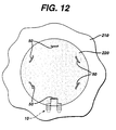
- FIG. 12 illustrates a matrix 220 mounted to bone surface 201 of bone 210 having multiple fixation devices of the present invention installed to secure the matrix 220.
- the number, anatomical location and orientation of fixation devices 10 necessary to provide sufficiently effective fixation will vary with the size and type of implant or matrix, the type of tissue, the age of the patient, the size of the patient's defect, the size of the fixation devices, the material of construction of the fixation devices, the load on the tissue at the repair site, etc.
- the size of the fixation devices of the present invention will vary in accordance with a number of variables including the specific design of the device, the materials of construction, the specific application for the devices, the type of surgical procedure, etc.
- the size of the matrices fixated with these devices will vary.
- the Figures which are part of this specification are merely schematic and illustrative of the device and method of the present invention; the actual dimensions of the devices and matrices may vary in practice.
- a punch tool 400 was used to create the two requisite bore holes in the subchondral bone to receive one graft fixation device of the present invention. Only one polydioxanone device (4mm tip-to-tip distance) was used to attach each matrix. To create the bore holes, the punch tool was centred in the defect, oriented in the sagittal plane, and hit or "tapped" with a slap hammer repeatedly until it penetrated several millimetres into the subchondral bone. Next, a 7mm diameter circular collagen matrix, saturated with saline, was placed in the defect and then blotted dry to remove excess saline.
- the inserter tool 250 When the inserter tool 250 was loaded with the graft fixation device 10 of the present invention, the device and inserter tool were centred above the matrix and oriented in the sagittal plane. The surgeon then located the previously created bore holes by slowly advancing the distal tips of the inserter through the matrix. Once the surgeon located the holes with the inserter tips, a hammer was used to advance fully the inserter tool (and implantation members 20 of the fixation device 10) through the matrix and into the subchondral bone. The inserter tool had a depth stop to prevent the implantation members 20 from being inserted too deeply, thereby assuring the proper placement of the implantation members through the matrix.
- FIG. 9 Another embodiment of the fixation device of the present invention having multiple retention members is seen in FIG. 9.
- the device 300 is seen to have a pair of implantation members 310.
- the implantation members 310 are substantially cylindrical members having longitudinal axis 311, distal ends 314 and proximal ends 312.
- Each implantation member 310 is seen to have a longitudinal passage 320.
- the members 310 are seen to have a distal frustoconical end 330, outer surface 350, and ridges 355 extending outward from surface 350.
- the members 310 are seen to be connected by a pair of retention members 340, having first and second ends 342 and 344 respectively.
- FIGS. 13-17 Yet another embodiment of a fixation device of the present invention is illustrated in FIGS. 13-17.
- the graft fixation device 500 is seen to have implantation members 520.
- the implantation members 520 are seen to be elongated members, preferably having a substantially cylindrical shape.
- the members 520 may have other geometric shapes including conical, pyramidal, polygonal, cubic, spherical, etc.
- the implantation members 520 are seen to have distal ends 522 and proximal ends 524.
- Each implantation member 520 is seen to have an outer surface 528 and a longitudinal axis 529.
- Each member 520 is also seen to have longitudinal passage 535 extending therethrough.
- the implantation members 520 are also seen to have optional frustoconical ends 530, and proximal end face surfaces 532. Although it is preferred that endface surfaces 532 be flat, endface surfaces 532 may also be angled, concave, convex, etc.
- Each endface surface 532 is seen to have central circular opening 536 in communication with passage 535.
- central opening 536 will have a circular cross-section, but it may have other geometric cross-sections as well including elliptical, polygonal, square, rectangular, combinations thereof and the like.
- Members 520 are also seen to have distal end face surfaces 537 having circular openings 538 in communication with passages 535.
- end face surfaces 537 have a sharp edge configuration, but may also have various widths with a rounded or flat configuration.
- the annular end face surface 537 is of de minimis thickness around opening 538, however this thickness would typically increase in the absence of a frustoconical end.
- the end surface 537 could have various widths as previously mentioned.
- Also seen to extend out from the surface 528 of member 520 are a series of optional projections 540 having tissue engagement edges 544.
- the surface 528 of the member 520 will be smooth, however, it will be appreciated that surface 528 could be rough, or could have a variety of conventional projections such as cones, hemispheres, rods, hooks, etc., and the like and equivalents thereof.
- the device 500 is seen to have graft retention member 550 connecting the implantation members 520.
- Retention member 550 is seen to be a band-like member preferably having an oval cross-section.
- the retention member 550 is seen to have first end 552, second end 554 and central section 555.
- First end 552 is seen to extend up from proximal endface surface 532 of the first member 520 while end 554 is seen to extend up from the proximal endface surface 532 of the other member 520.
- a section 557 of end 552 is seen to extend out from section 539 of surface 528, while section 558 of second end 554 is also seen to extend out from a section 539 of surface 528.
- the ends 554 and 552 of retention member 550 may if desired extend from or be mounted to any section of outer surface 528.
- the connecting member 550 is preferably seen to be bent or shaped into three segments including top segment 555 and leg segments 556.
- the top segment 555 is seen to an arc shaped member, and the leg segments 56 are seen to be preferably perpendicular to surfaces 532.
- connecting member 550 may have other geometric configurations including semicircular, arced, curved, triangular, polygonal, V-shaped, and the like and combinations thereof.
- connecting member 550 may be permanently affixed to the implantation members 520, or may be removably attached thereto in a variety of conventional manners, for example, a ball and socket joint, a plug joint, etc.
- Member 550 may be rigid or flexible. Member 550 will have a sufficient surface area to retain effectively a tissue-engineered matrix in place on a bone or other body surface.
- connecting member 550 will have an oval cross-section, but may have other geometric cross-sections as well including circular, elliptical, polygonal, square, rectangular, combinations thereof and the like. Member 550 may be rigid or flexible, and may have a single filamentary structure or have multiple interconnected filaments or members.
- the insertion device 600 is seen to be a substantially cylindrical member having proximal end 610 and distal end 620.
- Proximal end 610 is seen to have a flat end surface 612.
- Frustoconical end section 630 is seen to extend distally from distal end 620, although device 600 may have other configurations as well.
- distal end 620 can have any tapered or curved configuration, but it is preferred that it have a frustoconical end section extending therefrom.
- the frustoconical end section 630 is seen to have outer surface 632 and distal tip 640.
- the device 600 is also seen to have exterior surface 650. Extending through the device 600 is the longitudinal passage 660 having first circular opening 665 in communication therewith, and second circular opening 667 in tip 640 in communication therewith.
- the insertion devices 600 are used in combination with the fixation members of the present invention to engage the fixation member in bone simultaneously with tapping the bore holes into bone, thereby eliminating the need for a separate step to form the bore holes prior to inserting the fixation member.
- a fixation member 500 is mounted to prongs 700 extending from the distal end 415 of the shaft 405 of instrument 400.
- Each prong 700 is seen to have first cylindrical section 710 extending from the distal end 415 of the shaft 405.
- Each cylindrical section 710 is seen to have proximal end 711 and distal end 712, and receiving grooves 715.
- Extending from the distal end 712 of each first section 710 is the central pin section 720.
- Central pin section 720 is seen to have proximal end 722 and distal end 724.
- Extending distally from distal end 724 of central pin section 720 is the distal pin member 730.
- Distal pin member 730 is seen to have proximal end 732 and distal pointed end 734.
- the insertion device 600 may be molded into or affixed to the distal end of an implantation member 520, thereby forming a unitary structure as seen in FIG. 31 and FIG. 32.
- the insertion device 600 may be mounted to the distal end of an implantation member 520 in a conventional manner by gluing, cementing, mechanical fastening, friction fit, and the like and equivalents thereof.
- fixation member 500 of the present invention are used to affix a matrix to bone in the following manner.
- the implantation members 520 of a fixation device 500 are placed upon prongs 700 of an instrument 400 such that the leg members 556 are at least partially engaged in grooves 715 in first section 710 (see FIG. 21), and, intermediate sections 720 of pin members 700 are engaged in passages 535 of implantation members 520, while pin members 730 extend out from the distal ends of the implantation members 520.
- insertion devices 600 are placed over the pin members 730, such that the pin members 730 are engaged in passages 660, and such that the pointed piercing ends 734 extend beyond the distal ends 640 of the insertion devices 600.
- the tool 400 and the assembly consisting of fixation device 500 and insertion devices 600 are placed over a tissue matrix 220 placed upon a bone 210.
- the piercing points are then pressed through matrix 220 to contact the surface 211 of bone 210.
- a slap-hammer section of instrument 400 is engaged to drive the piercing points 734, insertion devices 600 and implantation members 520 into the bone 210 as bore holes 200 are formed in the bone.
- the instrument 400 is then withdrawn proximately, thereby removing the intermediate sections 720 of prongs 700 from the implantation members 520 and the pin members 730 from the insertion devices 600, leaving the insertion devices 600 and the implantation members 520 securely in the bone (as seen in FIG. 20).
- fixation devices of the present invention It is particularly preferred to use conventional remote visualisation surgical procedures when inserting the fixation devices of the present invention. For example, inserting a scope through a trocar cannula into the joint or body cavity, while insufflating the joint or body cavity.
- the insertion devices 600 will typically be made from a strong, hard, bio-absorbable material such that they can be driven into bone without fracturing or breaking.
- Examples of the types of materials which can be used to make the insertion devices 600 include polylactic acid, polyglycolic acid, tricalcium phosphate, calcium phosphate, tetracalcium phosphate and hydroxyapatite, and any copolymers, mixtures or blends thereof.
- the insertion devices 600 assist in forming the bore holes 200 while protecting the implantation members 520.
- FIGS. 22-23 illustrate a disposable distal end assembly 800 for an instrument 400 of the present invention.
- the distal end 415 of the shaft 405 of instrument 400 have screw threads 418, although other conventional detachable mounts may be used, for example a bayonet-type mount, locking levers and tabs, male and female mating sections, etc.
- the assembly 800 consists of housing 810 having proximal end 811 and distal end 817. Housing 810 is seen to have hollow cavity 815 therein. Cavity 815 is seen to be in communication with proximal end opening 812 and distal end openings 820. Member 810 is seen to have outer surface 822.
- Outer surface 822 is preferably knurled to facilitate the grasping and turning of the housing 810.
- Housing 810 is further seen to have distal end surface 825.
- the outer surface 822 is seen to have a tapered section 823 that tapers toward end face 825.
- Contained within cavity 815, on inner surface 818 are the screw threads 819.
- Assembly 800 is also seen to have driving pin members 830.
- Each driving pin member 830 is seen to have proximal disk member 832 mounted to proximal end 831, shaft section 834 and distal pointed end 838.
- Surrounding each opening 820 on the interior of the member 810 are the annular recesses 840.
- the assembly 800 is mounted to the distal end 415 of the instrument 400 in the following manner.
- the pins 830 are inserted into cavity 815 and through openings 820 such that the shafts 834 and distal piercing points 838 extend through end face 825, and the disk members 832 are contained within the annular recesses 840. Then, the housing 810 is mounted upon the threads of distal end 415 such that threads 418 engage mating threads 819, and screwed further such that the proximal end surfaces 833 of the disk members 832 are in contact with the distal end face 416 of distal end 415. After use in a surgical procedure, the assembly 800 is removed and discarded. A new sterile assembly 800 is utilised with a cleaned and sterilised instrument 400 for each new procedure.
- a disposable end assembly 900 for mounting to an insertion instrument 250 is illustrated.
- the insertion member 250 is seen to have distal end 264, having endface 265 and screw threads 266.
- the assembly 900 is seen to have housing 950.
- Housing 950 has proximal end 952 and distal end 956 and exterior surface 954. Extending from distal end 956 is the plate member 960.
- Plate member 960 is seen to have distal surface 962.
- the exterior surface 954 is seen to have optional knurling and distal tapered section 957 tapering into plate member 960.
- Housing 950 is seen to have internal cavity 955.
- Housing 950 is also seen to have proximal opening 951 in communication with cavity 955 and distal openings 970 also in communication therewith. Housing 950 is seen to have internal screw threads 959 extending from internal surface 958. Also contained within the interior of housing 950 in the distal end 956 is the recessed groove 980. Assembly 900 is mounted to the distal end 264 of instrument 250 in the following manner. Pins 910 are inserted through cavity 950 and openings 970 such that proximal members 922 are engaged in groove 980. Sections 920 and 930 of pins 910 extend through openings 970. Sections 920 are seen to have grooves 925.
- the housing 950 is screwed on to distal end 264 such that the threads 266 engage the mating internal threads 959 of housing 950.
- the housing is tightened until the distal end surface 265 of the distal end 264 engages the top surfaces 923 of members 922.
- fixation devices of the present invention and the combination of the fixation devices with insertion devices, and methods of using such devices and combinations, of the present invention have many advantages.
- the advantages include providing a fast and routine way to fixate a matrix of tissue engineered tissue or other tissue.
- the fixation devices and combinations because they eliminate the need for suture knot tying, can be utilized in arthroscopic surgical procedures that require a minimum of surgical incisions and thus greatly reduce patient morbidity.
- the fixation devices and combinations have been demonstrated to provide excellent matrix fixation without damaging the surrounding normal cartilaginous tissue, unlike the conventional fixation of chondral defect matrices with traditional suture that must be passed through (and thus damage) the surrounding tissue.
- the instruments of the present invention provide for a reusable section, and a disposable section that can be discarded.
Abstract
Description
- The field of art to which this invention relates is surgical fastening devices, in particular, surgical fastening devices for fixating tissue grafts to bone.
- The medical technology associated with tissue engineering has advanced at a rapid pace. In particular, it is now known to harvest cells from the human body, for example, chondrocytes and fibrochrondrocytes from the knee joint. These autologous cells are then cultured in a laboratory environment on a bio-absorbable matrix. The matrix will typically have a shape substantially similar to the tissue section that needs to be replaced. After a sufficient period of time in an appropriate culture medium at the proper environmental conditions, the harvested cells will grow on the matrix to form an implantable section of tissue having substantially the same physical configuration as the section of tissue which needs to be replaced in the patient. Such a tissue-engineered construct, consisting of cells on the matrix (or, alternatively, consisting of a matrix alone without cells), is then affixed to the bone site using conventionally known surgical fasteners including sutures, periosteal coverings, or fibrin glue.
- The advantages of tissue engineering are many, not the least of which is, for example, that it is now possible to replace cartilage with living cartilage tissue. In addition, the likelihood of rejection of the tissue implant is minimised since the cartilage tissue which has been grown in-vitro is identical to the autologous cartilage of the patient.
- Although existing matrix fixation devices are adequate for their intended use, there are also some disadvantages attendant with their use. First of all these fixation devices are generic in the sense that they are not specifically designed for matrix fixation to bone or soft tissue, but can be used for a variety of surgical procedures. Other disadvantages include the difficulty in using many of these devices in a minimally invasive arthroscopic procedure. Additional disadvantages include the difficulty and surgical challenge of harvesting a piece of periosteum for use as a periosteal flap, the significant patient morbidity associated with such harvesting, and the difficulty in suturing such a thin, compliant material to surrounding tissue.
- Accordingly, there is a need in this art for novel fixation devices that will effectively affix a matrix of tissue-engineered tissue to a bone or other anchoring site so that the tissue may continue to grow and regenerate in the patient's body.
- Therefore, it is an object of the present invention to provide a fixation device that effectively fixates a tissue-engineered matrix to a bone or other anchoring site, thereby enabling the implanted matrix to remain in place while the tissue continues to grow and regenerate.
- It is a further object of the present invention to provide such a device for fixating a matrix to a bone site which is easily installed using an arthroscopic procedure or an open procedure.
- It is yet a further object of the present invention to provide such a device for fixating a matrix to a bone site which does not require sutures or suture knot tying.
- It is still yet a further object of the present invention to provide a surgical method for fixating a matrix utilising such a device in a location within a patient's body.
- Accordingly, a graft fixation device is disclosed. The graft fixation device has first and second implantation members. The members are elongated and preferably have a cylindrical configuration. The members also have distal ends, proximal ends, and longitudinal axes. There are longitudinal passages extending through the entire length of each implantation member. The members have outer surfaces. The implantation members are connected to each other by a member having first and second ends and a central section. The member is preferably a rod member. The first end of the rod member extends from the proximal end of the first implantation member and the second end of the rod member extends from the proximal end of the second implantation member. The rod member is preferably relatively rigid and may be configured to have a variety of geometric shapes, for example, an inverted "U" shape. However, the rod member may also be flexible. The rod member maintains the implantation members at a relatively fixed distance from each other. The central section of the rod member is designed to engage a section of a tissue-engineered matrix implant. In a preferred embodiment, the implantation members have a series of ridges extending out from the outer surfaces of the implantation members to assist in preventing withdrawal from a bone site or other anchoring site after the implantation members are implanted into previously-created bore holes.
- Still yet another aspect of the present invention is a graft fixation device combination which is the combination of a fixation device and an insertion device. The fixation device has a first implantation member. The implantation member has a longitudinal axis, a proximal end, a distal end, an outer surface, and a longitudinal passage therethrough. The fixation device also has a second implantation member. The second implantation member has a longitudinal axis, a proximal end, a distal end, an outer surface, and a longitudinal passage therethrough. Each implantation member preferably has a proximal annular face on its proximal end surrounding the longitudinal passages. There is a connecting member connecting the first and second implantation members. The connecting member has a central section, a first end extending from the first implantation member and a second end extending from the second implantation member.
- Preferably there are a pair of insertion devices. Each insertion device is a member having a proximal end, a distal tapered end and a longitudinal passage therethrough. The distal end of each implantation member is engageable with the proximal end of an insertion device.
- Another aspect of the present invention is the above described combination wherein an insertion device is mounted to the distal end of one of the, or each of the, implantation members.
- Yet another aspect of the present invention is an insertion instrument for inserting the fixation devices and/or combinations of the present invention in bone. The instrument has a removable distal end housing and removable prongs. The instrument has an elongated member having a proximal end, a distal end, a distal end surface, and an outer surface. Outer screw threads extend out from the outer surface about the distal end. There is a hollow member having a cavity, a proximal end and a distal end, and an outer surface and an inner surface, said hollow member having an opening in the proximal end in communication with the hollow cavity. Inner screw threads extend out from the inner surface of the hollow member. A pair of spaced apart prong holes extend through the distal end of the hollow member, said prong holes being in communication with the cavity. A retention groove extends into the inner surface of the distal end of the hollow member. There are a pair of prongs, said prongs having elongated members having distal ends and proximal ends. In a preferred embodiment, a piercing point extends distally from the distal end of each prong. A retention member is mounted to the proximal end of each prong, and the retention member has a proximal surface. The instrument is assembled by inserting the prongs through the prong holes, such that the prongs extend through the prong holes, and the proximal retention members are contained within the retention groove. The hollow member is then screwed onto the distal end of the elongated member, by engaging the mating inner threads with the outer threads, and rotating the hollow member until the distal end surface of the elongated member is in engagement with the proximal surfaces of the retention members.
- Still yet another aspect of the present invention is the combination of the insertion instrument as described above and a graft fixation device and/or combination of the present invention.
- Yet another aspect of the present invention is a method of using the graft fixation device of the present invention to affix a matrix containing tissue-engineered tissue to a bone.
- Yet another aspect of the present invention is a method of mounting a first article to a second article, in particular using the previously described device or combination. The combination of a graft fixation device and a pair of insertion devices may be provided. The fixation device has a first implantation member, said implantation member having a longitudinal axis, a proximal end, a distal end, an outer surface, and a longitudinal passage therethrough. The fixation device also has a second implantation member, said second implantation member having a longitudinal axis, a proximal end, a distal end, an outer surface, and a longitudinal passage therethrough.
- There is an optional proximal annular face on the proximal ends of the first and second implantation members surrounding the proximal opening to the longitudinal passage.
- A connecting member connects the first and second implantation members, the connecting member has a central section, a first end extending from the first implantation member and a second end extending from the second implantation member. As mentioned above, a pair of insertion devices may also be provided. Each insertion device consists of a member having a proximal end, a distal tapered end and a longitudinal passage therethrough. The distal end of each implantation member is engageable with the proximal end of an insertion device and, in use, is in engagement therewith.
- Optionally, an insertion device is molded into the distal end of each implantation member.
- Next, the combination of the fixation device and the insertion devices is mounted to an insertion instrument having a pair of spaced apart prongs, said prongs having distal ends and distal pointed tips extending therefrom, such that the prongs are contained within the passages of the implantation members and insertion members, and such that the distal tips of the prongs extend beyond the distal ends of the insertion members. The distal end of each implantation member is then engaged with the proximal end of each insertion device.
- A matrix is placed upon a bone. Then the implantation members and insertion devices are driven through the matrix into the bone, thereby securing the matrix to the bone.
- Yet another aspect of the present invention is the above-described method, wherein the insertion devices are mounted to the implantation members prior to mounting onto the prongs of the insertion instrument, such that the combination is mounted on the prongs in a single step.
- These and other features and advantages of the present invention will become more apparent from the following description and accompanying drawings.
-
- FIG. 1 is a perspective view of a graft fixation device of the present invention.
- FIG. 2 is a cross-sectional view of the graft fixation device of FIG. 1 taken along view line 2-2.
-
- FIGS. 3-6 illustrate a surgical procedure for affixing a matrix to bone using the graft fixation device of the present invention.
- FIG. 7 is an illustration of a graft fixation device of the present invention after the implantation members have been implanted in bore holes in bone illustrating the device affixing a matrix securely to the surface of a bone.
- FIG. 8 is a cross-sectional view of the graft fixation device of FIG. 7 implanted in bone, and taken along View Line 8-8.
- FIG. 9 is an alternative embodiment of a graft fixation device of the present invention having two connecting members.
- FIG. 10 is a perspective view of an instrument useful for making bore holes in bone into which the implantable members of the graft fixation devices of the present invention may be emplaced.
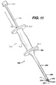
- FIG. 11 is a perspective view of an instrument useful for implanting the device of the present invention into bore holes made in bone.
- FIG. 12 is a view of a tissue engineered matrix secured to a bone with several graft fixation devices of the present invention.
- FIG. 13 is a perspective view of an alternate embodiment of a graft fixation device of the present invention.
- FIG. 14 is a side view of the graft fixation device of FIG. 13.
- FIG. 15 is an end view of the graft fixation device of FIG. 14.
- FIG. 16 is a cross-sectional view of the graft fixation device of FIG. 14, taken along View-Line 16-16.
- FIG. 17 is a cross-sectional view of the tissue retention member of the graft fixation device of FIG. 14, taken along View-Line 17-17.
- FIG. 18 is a perspective view of an insertion device useful for a graft fixation device of the present invention.
- FIG. 19 is an exploded perspective view of an insertion instrument, a graft fixation device, and two insertion devices.
- FIG. 20 is a side view of the distal end of the insertion instrument, a graft fixation device, and insertion devices engaged in bone, prior to removal of the insertion instrument.
- FIG. 21 is a cross-sectional view taken along View-Line 21-21 of FIG. 20 of the prong of the insertion instrument, and a section of the retention member engaged in a longitudinal groove of the prong.
- FIG. 22 is an exploded perspective view of the distal end of an insertion instrument of the present invention, illustrating a removable distal end assembly for creating bore holes in bone for receiving the fixation devices of the present invention, wherein the assembly has an end member and pins.
- FIG. 23 is a cross-section of the assembly end member of FIG. 22, taken along View-
Line 23. - FIG. 24 is a perspective view of the assembly end of FIG. 22, completely assembled and ready for use.
- FIG. 25 is a cross-sectional view of the end assembly of FIG. 24, taken along View-Line 25-25.
- FIG. 26 is an exploded perspective view of an insertion instrument of the present invention having a removable distal end assembly useful for inserting the graft retention members of the present invention into bore holes in a bone, having an end assembly member and two pins; when used with insertion devices, the instrument can be used to emplace the fixation device directly into bone without first forming bone bore holes.
- FIG. 27 is a cross-sectional view of the end assembly member of FIG. 26.
- FIG. 28 is a perspective view of the distal end of the insertion instrument of FIG. 26, having the end assembly member and prongs fully assembled and mounted.
- FIG. 29 is a cross-sectional view of the distal end of the insertion instrument of FIG. 28 take along View-Line 29-29.
- FIG. 30 is a cross-sectional view of the instrument of FIG. 29 taken along View-Line 30-30.
- FIG. 31 illustrates a fixation device of the present member having an insertion device molded into the distal end of each implantation member.
- FIG. 32 is a cross-sectional view of the fixation device of FIG 31.
- The graft fixation devices of the present invention can be made from conventional bio-compatible materials, including absorbable and non-absorbable materials, as well as biodegradable materials. The non-absorbable materials which can be utilised include conventional biocompatible materials such as stainless steel, polyethylene, Teflon (RTM), Nitinol (RTM), non-absorbable polymers, other bio-compatible metals, ceramics, combinations thereof and the like. The absorbable materials which can be used to manufacture the graft fixation devices of the present invention will typically include those conventional bio-absorbable or bio-resorbable materials known in this art which can be effectively molded or machined. The bio-absorbable and bio-resorbable materials include polylactic acid, polydioxanone, polycaprolactone, polyglycolic acid, polygalactic acid, other known biocompatible bio-absorbable and bio-resorbable polymers, ceramics, composites, combinations thereof and the like and equivalents thereof.
- Referring now to FIGS. 1-2, a preferred embodiment of a
graft fixation device 10 of the present invention is illustrated. Thegraft fixation device 10 is seen to haveimplantation members 20. Theimplantation members 20 are seen to be elongated members, preferably having a substantially cylindrical shape. Themembers 20 may have other geometric shapes including conical, pyramidal, polygonal, cubic, spherical, etc. Theimplantation members 20 are seen to havedistal ends 22 and proximal ends 24. Eachimplantation member 20 is seen to have an outer surface 28 and alongitudinal axis 29. Eachmember 20 is also seen to havelongitudinal passage 35 extending therethrough. Theimplantation members 20 are also seen to have optional frustoconical ends 30, and proximal endface surfaces 32. Although it is preferred that endface surfaces 32 be flat,endface surface 32 may also be angled, concave, convex, etc.Endface surface 32 is seen to have centralcircular opening 36 in communication withpassage 35. Preferably,central opening 36 will have a circular cross-section, but it may have other geometric cross-sections as well including elliptical, polygonal, square, rectangular, combinations thereof and the like.Members 20 are also seen to have distal end face surfaces 37 having circular openings 38 in communication withpassages 35. As shown with the optionalfrustoconical end 30, the annular end face surface 37 is of de minimis thickness around opening 38, however this thickness would increase in the absence of a frustoconical end. Also seen to extend out from the surface 28 ofmember 20 are a series ofoptional projections 40 having tissue engagement edges 44. Without theprojections 40, the surface 28 of themember 20 will be smooth. - The
device 10 is seen to havegraft retention member 50 connecting theimplantation members 20.Retention member 50 is seen to be a rod-like member havingfirst end 52,second end 54 andcentral section 55.First end 52 is seen to extend fromproximal endface surface 32 of thefirst member 20 whileend 54 is seen to extend up from theproximal endface surface 32 of theother member 20. The ends 54 and 52 ofretention member 50 may also if desired extend from or be mounted to any section of outer surface 28. The connectingmember 50 is seen to be preferably bent or shaped into three segments includingtop segment 55 andleg segments 56. Thetop segment 55 is seen to be substantially perpendicular to theleg segments 56. Although it is preferred that connectingmember 50 have an inverted "U" configuration, the connectingmember 50 may have other geometric configurations including semicircular, arced, curved, triangular, polygonal, V-shaped, and the like and combinations thereof. The ends 52 and 54 of connectingmember 50 may be permanently affixed to theimplantation members 20, or may be removably attached thereto in a conventional manner.Member 50 may be rigid or flexible.Member 50 will have a sufficient surface area to effectively retain a tissue-engineered matrix in place on a bone or other body surface. Preferably, connectingmember 50 will have a circular cross section, but may have other geometric cross-sections as well including elliptical, polygonal, square, rectangular, combinations thereof and the like.Member 50 may be rigid or flexible, and may have a single filamentary structure or have multiple interconnected filaments or members. - Referring now to FIGS. 3-8, the use of the
graft fixation devices 10 of the present invention in a surgical procedure is illustrated. Referring first to FIG. 3, the initial step, prior to the installation of a matrix containing a tissue-engineered tissue using agraft fixation device 10 of the present invention, is to drill or "tap" two boreholes 200 into abone 210, for example, subchondral bone in the knee joint. The bore holes 200 are seen to be cylindrical holes having a bottom 208 and anopen top 202 andside walls 205. - Optionally, the bore holes may be bone tunnels with a continuous passage and no bottom, or an open bottom. It is particularly preferred to tap the holes in the bone by using an
instrument 400 as illustrated in FIG. 10 which has a proximal section conventionally referred to in this art as a "slap hammer" section. The term "tapping" or "tap" as used herein is defined to mean a procedure wherein the distal pointedprongs 420 extending from thedistal end 415 of theshaft 405 ofinstrument 400 are located over a bone site, and theproximal end 410 ofinstrument 400 is tapped or hit with slidable hammer handle 450 (of the "slap hammer"), which slides on shaft 460 betweenproximal end 410 andproximal stop 470, to form the bone bore holes 200. Thedistal end 465 of shaft 460 is connected toproximal end 410.Proximal stop 470 is mounted toproximal end 467. Hammer handle 450 is seen to have grasping section 451,collars 455 andlongitudinal passage 457. Those skilled in the art will appreciate that a similar pointed instrument may be used to "tap" in the bore holes into bone, that is, any instrument having a nail-like distal end. In addition, although not preferred, one bone bore hole at a time may be "tapped" in. If the surgeon decides to drill the bore holes into bone, any conventional surgical drilling apparatus may be used. After the bore holes 200 are formed into thebone 210, thematrix 220 containing tissue-engineering tissue is placed upon thebone surface 201 by the surgeon as seen in FIG. 4. - Next, the
graft fixation device 10 is mounted on to theinsertion instrument 250. -
Insertion instrument 250, as illustrated in FIG. 11, is seen to be anelongated rod 260 having aproximal end 262 and adistal end 264. Mounted to thedistal end 264 of therod 260 is thedepth stop 290. Thedepth stop 290 is seen to be a substantially rectangular member which is mounted perpendicular to thelongitudinal axis 251 of the rod 260 (see Figure 7).Depth stop 290 is seen to have bottom 292. Extending distally from the bottom 292 ofplate member 290 is a pair of parallel, spaced-apart, mountingprongs 270. The mountingprongs 270 are seen to be substantially rod-like members having distal pointedtips 277 and proximal ends 272. Theprongs 270 are seen to havefirst section 273 anddistal section 275.Section 273 is seen to have a greater cross-sectional dimension thandistal section 275 such that theentire section 275 is insertable intopassages 35 ofmembers 20, whileproximal section 273 is not insertable therein. -
Instrument 250 is also seen to have a "slap hammer section" consisting ofproximal shaft 300 extending fromproximal end 262, slidable hammer handle 320 (the "slap hammer") which is slidable uponshaft 300 betweenproximal end 262, andproximal stop 330.Hammer handle member 320 is seen to have graspingsection 325,end collars 327 andlongitudinal passage 329. Thegraft fixation device 10 is mounted to theinsertion instrument 250 by sliding theimplantation members 20 onto theprongs 270 such that thedistal sections 275 ofmembers 270 are engaged within thelongitudinal passages 35 ofmembers 20 anddistal points 277 protrude beyond the end of distal endface surfaces 37. Then, as seen in FIGS. 5 and 6, theinstrument 250 is manipulated such that thegraft fixation device 10 is inserted throughmatrix 220 and intobone 210 by moving theimplantation members 20 mounted onprongs 270 into the bore holes 200 such that themembers 20 are engaged in the bore holes 200, and such that thetissue engagement section 55 of theretention member 50 engages thematrix 220 such that thematrix 220 is firmly engaged against thesurface 201 of thebone 210. If desired, holes may be cut intomatrix 220 prior to insertion ofdevice 10. Then, as seen in FIG. 7, theinsertion instrument 250 is withdrawn proximally causing theprongs 270 to be withdrawn from thepassages 35 of theimplantation members 20, thereby leaving thegraft fixation device 10 engaged in the bone bore holes, and causing thematrix 220 to be maintained in engagement with thesurface 201 ofbone 210. - The "slap hammer" section of
instrument 250 may assist in removal of the prongs. - A cross-sectional view illustrating the
device 10 engaged inbone 210 while maintaining thematrix 220 onbone surface 201 is seen in FIG. 8. - FIG. 12 illustrates a
matrix 220 mounted tobone surface 201 ofbone 210 having multiple fixation devices of the present invention installed to secure thematrix 220. The number, anatomical location and orientation offixation devices 10 necessary to provide sufficiently effective fixation will vary with the size and type of implant or matrix, the type of tissue, the age of the patient, the size of the patient's defect, the size of the fixation devices, the material of construction of the fixation devices, the load on the tissue at the repair site, etc. - Those skilled in the art will appreciate that the size of the fixation devices of the present invention will vary in accordance with a number of variables including the specific design of the device, the materials of construction, the specific application for the devices, the type of surgical procedure, etc. Similarly, the size of the matrices fixated with these devices will vary. The Figures which are part of this specification are merely schematic and illustrative of the device and method of the present invention; the actual dimensions of the devices and matrices may vary in practice.
- The following example is illustrative of the principles and practice of the present invention although not limited thereto.
- Six sheep were prepared for a surgical procedure using standard aseptic surgical techniques including the use of fully sterilised instruments and equipment, and conventional anaesthesia procedures and protocols. The surgeon then created 7mm diameter chondral (full thickness cartilage) defects on a weight-bearing area of the medial femoral condyle and in the trochlear groove in the right stifle (knee) in each of the six skeletally mature sheep. Defects were created using a specialised drill with a depth-stop to prevent subchondral bone exposure or penetration. The base surfaces of all the defects were then microfractured with a specialised micropick tool to provide access for cellular migration. The subjects were then separated into three groups of two subjects each:
- Group 1: defect filled with a collagen matrix, fixed with the graft fixation device of the present invention.
- Group 2: defect filled with a collagen matrix, fixed with 9-0 absorbable Vicryl (RTM) suture (interrupted stitch technique, approximately 12 strands per matrix).
- Group 3: unfilled defect (control group).
-
- Both defects in a given stifle received the same treatment or served as controls.
- For the two sheep in Group 1, after a defect had been created and micro fractured, a
punch tool 400 was used to create the two requisite bore holes in the subchondral bone to receive one graft fixation device of the present invention. Only one polydioxanone device (4mm tip-to-tip distance) was used to attach each matrix. To create the bore holes, the punch tool was centred in the defect, oriented in the sagittal plane, and hit or "tapped" with a slap hammer repeatedly until it penetrated several millimetres into the subchondral bone. Next, a 7mm diameter circular collagen matrix, saturated with saline, was placed in the defect and then blotted dry to remove excess saline. When theinserter tool 250 was loaded with thegraft fixation device 10 of the present invention, the device and inserter tool were centred above the matrix and oriented in the sagittal plane. The surgeon then located the previously created bore holes by slowly advancing the distal tips of the inserter through the matrix. Once the surgeon located the holes with the inserter tips, a hammer was used to advance fully the inserter tool (andimplantation members 20 of the fixation device 10) through the matrix and into the subchondral bone. The inserter tool had a depth stop to prevent theimplantation members 20 from being inserted too deeply, thereby assuring the proper placement of the implantation members through the matrix. The insertion was completed when the connecting retention member between the two implantation members initially started to compress the collagen matrix, thereby indicating secure fixation with the underlying subchondral bone. After the two defects in a given stifle had each been repaired with a matrix and fixation device, the stifle was closed and the sheep was allowed to recover. It was noted by the surgeon that it took approximately one minute to attach a matrix with a fixation device of the present invention (Group 1), versus approximately 15 minutes to attach a matrix with suture alone and the requisite suture manipulation and knot tying (Group 2). - Two weeks after the surgeries were completed, the knee joints were surgically opened for examination. Gross macroscopic assessment of the joints demonstrated that all four matrices held by the graft fixation device of the present invention were fully intact. However, all four matrices held by sutures alone were only partially intact with, on average, approximately 30% of the sutures broken on any given matrix.
- Another embodiment of the fixation device of the present invention having multiple retention members is seen in FIG. 9. The
device 300 is seen to have a pair ofimplantation members 310. Theimplantation members 310 are substantially cylindrical members havinglongitudinal axis 311, distal ends 314 and proximal ends 312. Eachimplantation member 310 is seen to have alongitudinal passage 320. Themembers 310 are seen to have a distalfrustoconical end 330, outer surface 350, and ridges 355 extending outward from surface 350. Themembers 310 are seen to be connected by a pair ofretention members 340, having first and second ends 342 and 344 respectively. - Yet another embodiment of a fixation device of the present invention is illustrated in FIGS. 13-17. The
graft fixation device 500 is seen to haveimplantation members 520. Theimplantation members 520 are seen to be elongated members, preferably having a substantially cylindrical shape. Themembers 520 may have other geometric shapes including conical, pyramidal, polygonal, cubic, spherical, etc. Theimplantation members 520 are seen to havedistal ends 522 and proximal ends 524. Eachimplantation member 520 is seen to have anouter surface 528 and alongitudinal axis 529. Eachmember 520 is also seen to havelongitudinal passage 535 extending therethrough. Theimplantation members 520 are also seen to have optional frustoconical ends 530, and proximal end face surfaces 532. Although it is preferred that endface surfaces 532 be flat, endface surfaces 532 may also be angled, concave, convex, etc. Eachendface surface 532 is seen to have centralcircular opening 536 in communication withpassage 535. Preferably,central opening 536 will have a circular cross-section, but it may have other geometric cross-sections as well including elliptical, polygonal, square, rectangular, combinations thereof and the like.Members 520 are also seen to have distal end face surfaces 537 havingcircular openings 538 in communication withpassages 535. Preferably, end face surfaces 537 have a sharp edge configuration, but may also have various widths with a rounded or flat configuration. As shown with the optionalfrustoconical end 530, the annularend face surface 537 is of de minimis thickness aroundopening 538, however this thickness would typically increase in the absence of a frustoconical end. However, although not preferred, even with a frustoconical, theend surface 537 could have various widths as previously mentioned. Also seen to extend out from thesurface 528 ofmember 520 are a series ofoptional projections 540 having tissue engagement edges 544. Without theprojections 540, thesurface 528 of themember 520 will be smooth, however, it will be appreciated thatsurface 528 could be rough, or could have a variety of conventional projections such as cones, hemispheres, rods, hooks, etc., and the like and equivalents thereof. - The
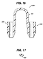
device 500 is seen to havegraft retention member 550 connecting theimplantation members 520.Retention member 550 is seen to be a band-like member preferably having an oval cross-section. Theretention member 550 is seen to havefirst end 552,second end 554 andcentral section 555.First end 552 is seen to extend up fromproximal endface surface 532 of thefirst member 520 whileend 554 is seen to extend up from theproximal endface surface 532 of theother member 520. Asection 557 ofend 552 is seen to extend out fromsection 539 ofsurface 528, whilesection 558 ofsecond end 554 is also seen to extend out from asection 539 ofsurface 528. The ends 554 and 552 ofretention member 550 may if desired extend from or be mounted to any section ofouter surface 528. The connectingmember 550 is preferably seen to be bent or shaped into three segments includingtop segment 555 andleg segments 556. Thetop segment 555 is seen to an arc shaped member, and theleg segments 56 are seen to be preferably perpendicular tosurfaces 532. Although it is preferred that connectingmember 550 have an inverted "U" configuration, the connectingmember 50 may have other geometric configurations including semicircular, arced, curved, triangular, polygonal, V-shaped, and the like and combinations thereof. The ends 552 and 554 of connectingmember 550 may be permanently affixed to theimplantation members 520, or may be removably attached thereto in a variety of conventional manners, for example, a ball and socket joint, a plug joint, etc.Member 550 may be rigid or flexible.Member 550 will have a sufficient surface area to retain effectively a tissue-engineered matrix in place on a bone or other body surface. Preferably, connectingmember 550 will have an oval cross-section, but may have other geometric cross-sections as well including circular, elliptical, polygonal, square, rectangular, combinations thereof and the like.Member 550 may be rigid or flexible, and may have a single filamentary structure or have multiple interconnected filaments or members. - Another aspect of the present invention is a distal insertion device (or member) useful with the fixation devices of the present invention. As seen in FIG. 18, the
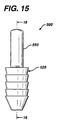
insertion device 600 is seen to be a substantially cylindrical member havingproximal end 610 anddistal end 620.Proximal end 610 is seen to have aflat end surface 612.Frustoconical end section 630 is seen to extend distally fromdistal end 620, althoughdevice 600 may have other configurations as well. If desired,distal end 620 can have any tapered or curved configuration, but it is preferred that it have a frustoconical end section extending therefrom. Thefrustoconical end section 630 is seen to haveouter surface 632 anddistal tip 640. Thedevice 600 is also seen to haveexterior surface 650. Extending through thedevice 600 is thelongitudinal passage 660 having firstcircular opening 665 in communication therewith, and secondcircular opening 667 intip 640 in communication therewith. Theinsertion devices 600 are used in combination with the fixation members of the present invention to engage the fixation member in bone simultaneously with tapping the bore holes into bone, thereby eliminating the need for a separate step to form the bore holes prior to inserting the fixation member. - Referring to FIGS. 19-21, the previously mentioned combination of an
insertion device 600 and afixation member 500 is illustrated. Initially, afixation member 500 is mounted toprongs 700 extending from thedistal end 415 of theshaft 405 ofinstrument 400. Eachprong 700 is seen to have firstcylindrical section 710 extending from thedistal end 415 of theshaft 405. Eachcylindrical section 710 is seen to haveproximal end 711 anddistal end 712, and receivinggrooves 715. Extending from thedistal end 712 of eachfirst section 710 is thecentral pin section 720.Central pin section 720 is seen to haveproximal end 722 anddistal end 724. Extending distally fromdistal end 724 ofcentral pin section 720 is thedistal pin member 730.Distal pin member 730 is seen to haveproximal end 732 and distalpointed end 734. - If desired, the
insertion device 600 may be molded into or affixed to the distal end of animplantation member 520, thereby forming a unitary structure as seen in FIG. 31 and FIG. 32. In addition, theinsertion device 600 may be mounted to the distal end of animplantation member 520 in a conventional manner by gluing, cementing, mechanical fastening, friction fit, and the like and equivalents thereof. - The combination of the
insertion devices 600 and fixation members, such asfixation member 500 of the present invention, are used to affix a matrix to bone in the following manner. Initially, theimplantation members 520 of afixation device 500 are placed uponprongs 700 of aninstrument 400 such that theleg members 556 are at least partially engaged ingrooves 715 in first section 710 (see FIG. 21), and,intermediate sections 720 ofpin members 700 are engaged inpassages 535 ofimplantation members 520, whilepin members 730 extend out from the distal ends of theimplantation members 520. Then,insertion devices 600 are placed over thepin members 730, such that thepin members 730 are engaged inpassages 660, and such that the pointed piercing ends 734 extend beyond the distal ends 640 of theinsertion devices 600. Then, thetool 400 and the assembly consisting offixation device 500 andinsertion devices 600 are placed over atissue matrix 220 placed upon abone 210. The piercing points are then pressed throughmatrix 220 to contact thesurface 211 ofbone 210. A slap-hammer section ofinstrument 400 is engaged to drive the piercingpoints 734,insertion devices 600 andimplantation members 520 into thebone 210 as bore holes 200 are formed in the bone. Theinstrument 400 is then withdrawn proximately, thereby removing theintermediate sections 720 ofprongs 700 from theimplantation members 520 and thepin members 730 from theinsertion devices 600, leaving theinsertion devices 600 and theimplantation members 520 securely in the bone (as seen in FIG. 20). This completes the affixation of thematrix 220 to thebone 210 using a single step, wherein the bore holes in the bone are formed simultaneously asinsertion devices 600 andfixation device 500 are emplaced in the bone. - It is particularly preferred to use conventional remote visualisation surgical procedures when inserting the fixation devices of the present invention. For example, inserting a scope through a trocar cannula into the joint or body cavity, while insufflating the joint or body cavity.
- The
insertion devices 600 will typically be made from a strong, hard, bio-absorbable material such that they can be driven into bone without fracturing or breaking. Examples of the types of materials which can be used to make theinsertion devices 600 include polylactic acid, polyglycolic acid, tricalcium phosphate, calcium phosphate, tetracalcium phosphate and hydroxyapatite, and any copolymers, mixtures or blends thereof. Although not preferred, it is possible to make theinsertion devices 600 from a conventional biocompatible material which is not bio-absorbable or biodegradable, such as titanium, stainless steel, ceramics, Nitinol and the like and equivalents thereof. Theinsertion devices 600 assist in forming the bore holes 200 while protecting theimplantation members 520. - FIGS. 22-23 illustrate a disposable
distal end assembly 800 for aninstrument 400 of the present invention. When using thedisposable assembly 800, it is preferable that thedistal end 415 of theshaft 405 ofinstrument 400 havescrew threads 418, although other conventional detachable mounts may be used, for example a bayonet-type mount, locking levers and tabs, male and female mating sections, etc. As seen in FIGS. 22-25, theassembly 800 consists ofhousing 810 havingproximal end 811 anddistal end 817.Housing 810 is seen to havehollow cavity 815 therein.Cavity 815 is seen to be in communication withproximal end opening 812 anddistal end openings 820.Member 810 is seen to haveouter surface 822.Outer surface 822 is preferably knurled to facilitate the grasping and turning of thehousing 810.Housing 810 is further seen to havedistal end surface 825. Theouter surface 822 is seen to have a taperedsection 823 that tapers towardend face 825. Contained withincavity 815, oninner surface 818 are thescrew threads 819.Assembly 800 is also seen to have drivingpin members 830. Each drivingpin member 830 is seen to haveproximal disk member 832 mounted toproximal end 831,shaft section 834 and distal pointed end 838. Surrounding each opening 820 on the interior of themember 810 are theannular recesses 840. Theassembly 800 is mounted to thedistal end 415 of theinstrument 400 in the following manner. Thepins 830 are inserted intocavity 815 and throughopenings 820 such that theshafts 834 and distal piercing points 838 extend throughend face 825, and thedisk members 832 are contained within theannular recesses 840. Then, thehousing 810 is mounted upon the threads ofdistal end 415 such thatthreads 418 engagemating threads 819, and screwed further such that the proximal end surfaces 833 of thedisk members 832 are in contact with thedistal end face 416 ofdistal end 415. After use in a surgical procedure, theassembly 800 is removed and discarded. A newsterile assembly 800 is utilised with a cleaned and sterilisedinstrument 400 for each new procedure. - Referring now to FIGS. 26-30, a
disposable end assembly 900 for mounting to aninsertion instrument 250 is illustrated. Theinsertion member 250 is seen to havedistal end 264, havingendface 265 andscrew threads 266. Theassembly 900 is seen to havehousing 950.Housing 950 hasproximal end 952 anddistal end 956 andexterior surface 954. Extending fromdistal end 956 is theplate member 960.Plate member 960 is seen to havedistal surface 962. Theexterior surface 954 is seen to have optional knurling and distal tapered section 957 tapering intoplate member 960.Housing 950 is seen to haveinternal cavity 955.Housing 950 is also seen to haveproximal opening 951 in communication withcavity 955 anddistal openings 970 also in communication therewith.Housing 950 is seen to haveinternal screw threads 959 extending frominternal surface 958. Also contained within the interior ofhousing 950 in thedistal end 956 is the recessedgroove 980.Assembly 900 is mounted to thedistal end 264 ofinstrument 250 in the following manner.Pins 910 are inserted throughcavity 950 andopenings 970 such thatproximal members 922 are engaged ingroove 980.Sections pins 910 extend throughopenings 970.Sections 920 are seen to have grooves 925. Then, thehousing 950 is screwed on todistal end 264 such that thethreads 266 engage the matinginternal threads 959 ofhousing 950. The housing is tightened until thedistal end surface 265 of thedistal end 264 engages thetop surfaces 923 ofmembers 922. After a surgical procedure, theassembly 900 is removed frominstrument 250 and discarded. A newsterile assembly 900 is utilised with a cleaned and sterilisedinstrument 250 for each new procedure. - The fixation devices of the present invention, and the combination of the fixation devices with insertion devices, and methods of using such devices and combinations, of the present invention have many advantages. The advantages include providing a fast and routine way to fixate a matrix of tissue engineered tissue or other tissue. The fixation devices and combinations, because they eliminate the need for suture knot tying, can be utilized in arthroscopic surgical procedures that require a minimum of surgical incisions and thus greatly reduce patient morbidity. In addition, the fixation devices and combinations have been demonstrated to provide excellent matrix fixation without damaging the surrounding normal cartilaginous tissue, unlike the conventional fixation of chondral defect matrices with traditional suture that must be passed through (and thus damage) the surrounding tissue. The instruments of the present invention provide for a reusable section, and a disposable section that can be discarded.
- Although this invention has been shown and described with respect to detailed embodiments thereof, it will be understood by those skilled in the art that various changes in form and detail may be made without departing from the scope of the claimed invention.
Claims (32)
- A graft fixation device comprising the combination of:i) a fixation device, comprising:a first implantation member, said implantation member having a longitudinal axis, a proximal end, a distal end, an outer surface, and a longitudinal passage therethrough;a second implantation member, said implantation member having a longitudinal axis, a proximal end, a distal end, an outer surface, and a longitudinal passage therethrough;a connecting member connecting the first and second implantation members, the connecting member having a central section, a first end extending from the first implantation member and a second end extending from the second implantation member; andii) at least one insertion device, the insertion device comprising a member having a proximal end, a distal tapered end and a longitudinal passage therethrough, wherein:
the distal end of one or each implantation member is in engagement with the proximal end of an insertion device. - The device of claim 1, wherein the implantation members have a series of ridges extending from the outer surfaces thereof.
- The device of claim 1 or 2, wherein the connecting member is shaped into a configuration having a central section and rod members, wherein the rod members are substantially parallel to the longitudinal axes of the implantation members, and the central section is substantially perpendicular to the rod members.
- The device of claim 1, 2 or 3, wherein the connecting member has a semi-circular configuration.
- The device of any one of the preceding claims, additionally comprising a frustoconical end extending from the distal end of the first implantation member and the distal end of the second implantation member.
- The device of any one claims 1 to 4, wherein the implantation members have a cylindrical configuration.
- The device of any one of the preceding claims, wherein the insertion device comprises a bio-absorbable material selected from the group consisting of polylactic acid, polyglycolic acid, tricalcium phosphate, calcium, phosphate, tetracalcium phosphate and hydroxyapatite, and copolymers, mixtures and blends thereof.
- The device of any one of claims 1 to 6, wherein the insertion device comprises a biocompatible material selected from the group consisting of titanium, stainless steel, ceramic, and Nitinol (RTM).
- The device of any one of the preceding claims, wherein the fixation device comprises a bio-absorbable polymer.
- The device of any one of the preceding claims, comprising a pair of insertion devices.
- An instrument for inserting a graft fixation device into bone, said instrument comprising:an elongated member having a proximal end, a distal end and an outer surface;an outer screw thread extending out from the outer surface about the distal end;a distal end surface adjacent to the distal end of the elongated member;a hollow member having a cavity, a proximal end, a distal end, an outer surface and an inner surface, said hollow member having an opening in the proximal end in communication with the cavity;inner screw threads extending out from the inner surface of the hollow member;a pair of spaced apart prong holes extending through the distal end of the hollow member, said prong holes being in communication with the cavity;a retention groove extending into the inner surface of the distal end of the hollow member;a pair of prongs, said prongs comprising elongated members having distal ends and proximal ends;a point extending distally from the distal end of each prong; anda retention member mounted to the proximal end of each prong, the retention member having a proximal surface;wherein the instrument is assembled by first inserting the prongs through the prong holes such that the prongs extend through the prong holes and the proximal retention members are contained within the retention groove, and the hollow member is then screwed onto the distal end of the elongated member, by engaging the mating inner threads with the outer threads, such that the distal end surface of the elongated member engages the proximal surface of each retention member.
- The instrument of claim 11, wherein the prongs have a first proximal section having a first diameter and a second distal section having a second diameter, and wherein the first diameter is greater than the second diameter.
- The instrument of claim 11 or 12, wherein the prongs each have a longitudinal groove for receiving at least a section of a connecting member of a retention device;
- The instrument of any one of claims 11 to 13, wherein the point of each prong comprises a piercing point.
- A combination comprising:i) an instrument for inserting a graft fixation device into bone, said instrument comprising:an elongated member having a proximal end and a distal end and an outer surface;outer screw threads extending out from the outer surface about the distal end;a distal end surface adjacent to the distal end of the elongated member;a hollow member having a cavity, a proximal end, a distal end, an outer surface and an inner surface, said hollow member having an opening in the proximal end in communication with the cavity;inner screw threads extending out from the inner surface of the hollow member;a pair of spaced apart prong holes extending through the distal end of the hollow member, said prong holes being in communication with the cavity;a retention groove extending into the inner surface of the distal end of the hollow member;a pair of prongs, said prongs comprising elongated members having distal ends and proximal ends;a point extending distally from the distal end of each prong; anda retention member mounted to the proximal end of each prong, the retention member having a proximal surface;wherein the instrument is assembled by first inserting the prongs through the prong holes, such that the prongs extend through the prong holes and the proximal retention members are contained within the retention groove, and the hollow member is then screwed onto the distal end of the elongated member, by engaging the mating inner threads with the outer threads, such that the distal end surface of the elongated member engages the proximal surface of each retention member; andii) a graft fixation device disposable on the prongs of the instrument.
- The combination of claim 15, wherein the instrument comprises the features of any one of claims 12 to 14.
- The combination of claim 15 or 16, wherein the graft fixation device comprises the features of any one of claims 1 to 10.
- A method of mounting a first article to a second article, comprising the steps of:providing a device comprising the combination of:i) a fixation device, comprising:a first implantation member, said implantation member having a longitudinal axis, a proximal end, a distal end, an outer surface, and a longitudinal passage therethrough;a second implantation member, said implantation member having a longitudinal axis, a proximal end, a distal end, an outer surface, and a longitudinal passage therethrough;a connecting member connecting the first and second implantation members, the connecting member having a central section, a first end extending from the first implantation member and a second end extending from the second implantation member; and,ii) a pair of insertion devices, each insertion device comprising:a member having a proximal end, a distal tapered end and a longitudinal passage therethrough,wherein the distal end of each implantation member is in engagement with the proximal end of an insertion device;mounting the combination to an insertion instrument having a pair of spaced apart prongs, said prongs having distal ends and distal tips extending therefrom, such that the prongs are contained within the passages of the implantation members, such that the distal tips of the prongs extend beyond the distal ends of the insertion members;placing a first article onto the surface of a second article;and inserting the implantation members through the first article and into the second article thereby forming bore holes while simultaneously emplacing the implantation members in the second article, thereby securing the first article to the second article.
- The method of claim 18, wherein the implantation members have a series of ridges extending from the outer surfaces thereof.
- The method of claim 18 or 19, wherein the connecting member is shaped into a configuration having a central section and leg members, wherein the leg members are substantially parallel to the longitudinal axes of the implantation members, and the central section is substantially perpendicular to the rod members.
- The method of claim 18, 19 or 20, wherein the connecting member has a semi-circular configuration.
- The method of any one of claims 18 to 21, wherein the implantation members additionally comprise a frustoconical end extending from the distal end of the first implantation member and the distal end of the second implantation member.
- The method of any one of claims 18 to 22, wherein the implantation members have a cylindrical configuration.
- The method of any one of claims 18 to 23, wherein the distal tip of each prong comprises a piercing point extending from the distal end.
- The method of any one of claims 18 to 24, wherein each prong comprises a distal section having a cross-section and a proximal section having a cross-section, wherein the cross-section of the proximal section is greater than the cross-section of the distal cross-section.
- The method of any one of claims 18 to 25, wherein each prong has a circular cross-section.
- The method of any one of claims 18 to 26, wherein the insertion devices comprise a bio-absorbable material selected from the group consisting of polylactic acid, polyglycolic acid, tricalcium phosphate, calcium phosphate, tetracalcium phosphate and hydroxyapatite, and copolymers, mixtures and blends thereof.
- The method of any one of claims 18 to 26, wherein the insertion devices comprise a biocompatible material selected from the group consisting of titanium, stainless steel, ceramic, and Nitinol.
- The method of any one of claims 18 to 28, wherein an insertion device is affixed to each implantation member prior to mounting on the prongs of the insertion instrument.
- The method of claim 29, wherein the insertion devices are affixed by gluing.
- The method of any one of claims 18 to 29, wherein the insertion devices are co-molded with the fixation device.
- The method of any one of claims 18 to 31, conducted by using a remote visualisation scope.
Applications Claiming Priority (6)
| Application Number | Priority Date | Filing Date | Title |
|---|---|---|---|
| US535183 | 1990-06-08 | ||
| US09/535,189 US6447517B1 (en) | 1999-07-23 | 2000-03-27 | Instrument for inserting graft fixation device |
| US535187 | 2000-03-27 | ||
| US09/535,187 US6364884B1 (en) | 1999-07-23 | 2000-03-27 | Method of securing a graft using a graft fixation device |
| US09/535,183 US6497707B1 (en) | 1999-07-23 | 2000-03-27 | Graft fixation device combination |
| US535189 | 2000-03-27 |
Publications (3)
| Publication Number | Publication Date |
|---|---|
| EP1138263A2 true EP1138263A2 (en) | 2001-10-04 |
| EP1138263A3 EP1138263A3 (en) | 2001-12-05 |
| EP1138263B1 EP1138263B1 (en) | 2006-03-01 |
Family
ID=27415169
Family Applications (1)
| Application Number | Title | Priority Date | Filing Date |
|---|---|---|---|
| EP20010302831 Expired - Lifetime EP1138263B1 (en) | 2000-03-27 | 2001-03-27 | Graft fixation system |
Country Status (2)
| Country | Link |
|---|---|
| EP (1) | EP1138263B1 (en) |
| DE (1) | DE60117474T2 (en) |
Cited By (8)
| Publication number | Priority date | Publication date | Assignee | Title |
|---|---|---|---|---|
| EP1234545A2 (en) * | 2001-02-26 | 2002-08-28 | Ethicon, Inc. | Instrument for inserting graft fixation device |
| EP1236438A2 (en) * | 2001-02-26 | 2002-09-04 | Ethicon, Inc. | Graft fixation device combination |
| EP1330985A1 (en) * | 2002-01-24 | 2003-07-30 | Ethicon, Inc. | Graft fixation device combination |
| US7214232B2 (en) | 1999-07-23 | 2007-05-08 | Ethicon, Inc. | Graft fixation device |
| WO2010132280A1 (en) * | 2009-05-12 | 2010-11-18 | Ethicon, Inc. | Surgical fasteners, applicator instruments, and methods for deploying surgical fasteners |
| US8016867B2 (en) | 1999-07-23 | 2011-09-13 | Depuy Mitek, Inc. | Graft fixation device and method |
| US8579920B2 (en) | 2009-05-12 | 2013-11-12 | Ethicon, Inc. | Surgical fasteners, applicator instruments, and methods for deploying surgical fasteners |
| WO2014163814A1 (en) * | 2013-03-09 | 2014-10-09 | Ethicon, Inc. | Surgical fasteners having articulating joints and deflectable tips |
Families Citing this family (6)
| Publication number | Priority date | Publication date | Assignee | Title |
|---|---|---|---|---|
| USD744646S1 (en) | 2009-05-12 | 2015-12-01 | Ethicon, Inc. | Surgical fastener |
| US8728098B2 (en) | 2009-05-12 | 2014-05-20 | Ethicon, Inc. | Surgical fasteners, applicator instruments, and methods for deploying surgical fasteners |
| USD698021S1 (en) | 2009-05-12 | 2014-01-21 | Ethicon, Inc. | Surgical fastener |
| US9055945B2 (en) | 2009-05-12 | 2015-06-16 | Ethicon, Inc. | Surgical fasteners having articulating joints and deflectable tips |
| US8920439B2 (en) | 2009-05-12 | 2014-12-30 | Ethicon, Inc. | Applicator instruments having curved and articulating shafts for deploying surgical fasteners and methods therefor |
| US8728099B2 (en) | 2009-05-12 | 2014-05-20 | Ethicon, Inc. | Surgical fasteners, applicator instruments, and methods for deploying surgical fasteners |
Citations (8)
| Publication number | Priority date | Publication date | Assignee | Title |
|---|---|---|---|---|
| US4438769A (en) * | 1982-04-15 | 1984-03-27 | Pratt Clyde R | Medical staple device |
| US4884572A (en) * | 1986-05-20 | 1989-12-05 | Concept, Inc. | Tack and applicator for treating torn bodily material in vivo |
| EP0390613A1 (en) * | 1989-03-31 | 1990-10-03 | United States Surgical Corporation | Absorbable surgical fastener with bone penetrating elements |
| US5059206A (en) * | 1989-04-12 | 1991-10-22 | Winters Thomas F | Method and apparatus for repairing a tear in a knee meniscus |
| EP0589306A2 (en) * | 1992-09-21 | 1994-03-30 | United States Surgical Corporation | Device for applying a meniscal staple |
| EP0770354A1 (en) * | 1995-10-20 | 1997-05-02 | United States Surgical Corporation | Meniscal fastener applying apparatus |
| WO1999052478A1 (en) * | 1998-04-16 | 1999-10-21 | Axya Medical, Inc. | Sutureless soft tissue fixation assembly |
| US6022352A (en) * | 1997-03-28 | 2000-02-08 | Biomet, Inc. | Bone fixation screw system |
-
2001
- 2001-03-27 EP EP20010302831 patent/EP1138263B1/en not_active Expired - Lifetime
- 2001-03-27 DE DE2001617474 patent/DE60117474T2/en not_active Expired - Lifetime
Patent Citations (8)
| Publication number | Priority date | Publication date | Assignee | Title |
|---|---|---|---|---|
| US4438769A (en) * | 1982-04-15 | 1984-03-27 | Pratt Clyde R | Medical staple device |
| US4884572A (en) * | 1986-05-20 | 1989-12-05 | Concept, Inc. | Tack and applicator for treating torn bodily material in vivo |
| EP0390613A1 (en) * | 1989-03-31 | 1990-10-03 | United States Surgical Corporation | Absorbable surgical fastener with bone penetrating elements |
| US5059206A (en) * | 1989-04-12 | 1991-10-22 | Winters Thomas F | Method and apparatus for repairing a tear in a knee meniscus |
| EP0589306A2 (en) * | 1992-09-21 | 1994-03-30 | United States Surgical Corporation | Device for applying a meniscal staple |
| EP0770354A1 (en) * | 1995-10-20 | 1997-05-02 | United States Surgical Corporation | Meniscal fastener applying apparatus |
| US6022352A (en) * | 1997-03-28 | 2000-02-08 | Biomet, Inc. | Bone fixation screw system |
| WO1999052478A1 (en) * | 1998-04-16 | 1999-10-21 | Axya Medical, Inc. | Sutureless soft tissue fixation assembly |
Cited By (20)
| Publication number | Priority date | Publication date | Assignee | Title |
|---|---|---|---|---|
| US8016867B2 (en) | 1999-07-23 | 2011-09-13 | Depuy Mitek, Inc. | Graft fixation device and method |
| US7214232B2 (en) | 1999-07-23 | 2007-05-08 | Ethicon, Inc. | Graft fixation device |
| EP1236438A2 (en) * | 2001-02-26 | 2002-09-04 | Ethicon, Inc. | Graft fixation device combination |
| EP1234545A3 (en) * | 2001-02-26 | 2003-01-15 | Ethicon, Inc. | Instrument for inserting graft fixation device |
| EP1236438A3 (en) * | 2001-02-26 | 2003-12-17 | Ethicon, Inc. | Graft fixation device combination |
| AU784747B2 (en) * | 2001-02-26 | 2006-06-08 | Ethicon Inc. | Instrument for inserting graft fixation device |
| EP1234545A2 (en) * | 2001-02-26 | 2002-08-28 | Ethicon, Inc. | Instrument for inserting graft fixation device |
| EP1330985A1 (en) * | 2002-01-24 | 2003-07-30 | Ethicon, Inc. | Graft fixation device combination |
| AU2003200043B2 (en) * | 2002-01-24 | 2009-04-23 | Ethicon, Inc. | Graft fixation device combination |
| CN102458266A (en) * | 2009-05-12 | 2012-05-16 | 伊西康公司 | Surgical fasteners, applicator instruments, and methods for deploying surgical fasteners |
| WO2010132280A1 (en) * | 2009-05-12 | 2010-11-18 | Ethicon, Inc. | Surgical fasteners, applicator instruments, and methods for deploying surgical fasteners |
| US8579920B2 (en) | 2009-05-12 | 2013-11-12 | Ethicon, Inc. | Surgical fasteners, applicator instruments, and methods for deploying surgical fasteners |
| AU2010247959B2 (en) * | 2009-05-12 | 2015-01-22 | Ethicon, Llc | Surgical fasteners, applicator instruments, and methods for deploying surgical fasteners |
| RU2551934C2 (en) * | 2009-05-12 | 2015-06-10 | Этикон, Инк. | Surgical fastening components, applicators and methods of installing surgical fastening components |
| US9855041B2 (en) | 2009-05-12 | 2018-01-02 | Ethicon, Llc | Surgical fasteners for securing prosthetic devices to tissue |
| EP3412220A1 (en) * | 2009-05-12 | 2018-12-12 | Ethicon, Inc. | Surgical fasteners, and applicator instruments for deploying surgical fasteners |
| US10729433B2 (en) | 2009-05-12 | 2020-08-04 | Ethicon, Inc. | Applicator instruments for dispensing surgical fasteners having distal end caps with castling for engaging opposing surfaces |
| US11413039B2 (en) | 2009-05-12 | 2022-08-16 | Ethicon, Inc. | Applicator instruments for dispensing surgical fasteners having firing systems with slower piloting stages and faster dispensing stages |
| WO2014163814A1 (en) * | 2013-03-09 | 2014-10-09 | Ethicon, Inc. | Surgical fasteners having articulating joints and deflectable tips |
| AU2014249964B2 (en) * | 2013-03-09 | 2018-04-26 | Ethicon, Llc | Surgical fasteners having articulating joints and deflectable tips |
Also Published As
| Publication number | Publication date |
|---|---|
| EP1138263A3 (en) | 2001-12-05 |
| DE60117474D1 (en) | 2006-04-27 |
| DE60117474T2 (en) | 2006-11-09 |
| EP1138263B1 (en) | 2006-03-01 |
Similar Documents
| Publication | Publication Date | Title |
|---|---|---|
| US6447517B1 (en) | Instrument for inserting graft fixation device | |
| US6364884B1 (en) | Method of securing a graft using a graft fixation device | |
| US6497707B1 (en) | Graft fixation device combination | |
| US6436110B2 (en) | Method of securing a graft using a graft fixation device | |
| US6402766B2 (en) | Graft fixation device combination | |
| CA2417362C (en) | Graft fixation device combination | |
| EP1234545B1 (en) | Instrument for inserting graft fixation device | |
| CA2428348C (en) | Graft fixation device | |
| EP1138263B1 (en) | Graft fixation system | |
| CA2342038C (en) | Method of securing a graft using a graft fixation device | |
| CA2342037C (en) | Graft fixation device combination | |
| CA2342041C (en) | Instrument for inserting graft fixation device | |
| AU785000B2 (en) | Method of securing a graft using a graft fixation device |
Legal Events
| Date | Code | Title | Description |
|---|---|---|---|
| PUAI | Public reference made under article 153(3) epc to a published international application that has entered the european phase |
Free format text: ORIGINAL CODE: 0009012 |
|
| AK | Designated contracting states |
Kind code of ref document: A2 Designated state(s): AT BE CH CY DE DK ES FI FR GB GR IE IT LI LU MC NL PT SE TR Kind code of ref document: A2 Designated state(s): DE FR GB IT |
|
| AX | Request for extension of the european patent |
Free format text: AL;LT;LV;MK;RO;SI |
|
| PUAL | Search report despatched |
Free format text: ORIGINAL CODE: 0009013 |
|
| AK | Designated contracting states |
Kind code of ref document: A3 Designated state(s): AT BE CH CY DE DK ES FI FR GB GR IE IT LI LU MC NL PT SE TR |
|
| AX | Request for extension of the european patent |
Free format text: AL;LT;LV;MK;RO;SI |
|
| RIC1 | Information provided on ipc code assigned before grant |
Free format text: 7A 61B 17/064 A, 7A 61F 2/08 B, 7A 61B 17/068 B, 7A 61B 17/92 B |
|
| RIN1 | Information on inventor provided before grant (corrected) |
Inventor name: JANAS, VICTOR F. Inventor name: BOWMAN, STEVEN M. Inventor name: TENHUISEN, KEVOR S. |
|
| 17P | Request for examination filed |
Effective date: 20020514 |
|
| AKX | Designation fees paid |
Free format text: DE FR GB IT |
|
| 17Q | First examination report despatched |
Effective date: 20030821 |
|
| GRAP | Despatch of communication of intention to grant a patent |
Free format text: ORIGINAL CODE: EPIDOSNIGR1 |
|
| RTI1 | Title (correction) |
Free format text: GRAFT FIXATION SYSTEM |
|
| GRAS | Grant fee paid |
Free format text: ORIGINAL CODE: EPIDOSNIGR3 |
|
| GRAA | (expected) grant |
Free format text: ORIGINAL CODE: 0009210 |
|
| AK | Designated contracting states |
Kind code of ref document: B1 Designated state(s): DE FR GB IT |
|
| REG | Reference to a national code |
Ref country code: GB Ref legal event code: FG4D |
|
| RIN1 | Information on inventor provided before grant (corrected) |
Inventor name: JANAS, VICTOR F. Inventor name: TENHUISEN, KEVOR S. Inventor name: BOWMAN, STEVEN M. |
|
| REF | Corresponds to: |
Ref document number: 60117474 Country of ref document: DE Date of ref document: 20060427 Kind code of ref document: P |
|
| ET | Fr: translation filed | ||
| PLBE | No opposition filed within time limit |
Free format text: ORIGINAL CODE: 0009261 |
|
| STAA | Information on the status of an ep patent application or granted ep patent |
Free format text: STATUS: NO OPPOSITION FILED WITHIN TIME LIMIT |
|
| 26N | No opposition filed |
Effective date: 20061204 |
|
| REG | Reference to a national code |
Ref country code: FR Ref legal event code: PLFP Year of fee payment: 15 |
|
| PGFP | Annual fee paid to national office [announced via postgrant information from national office to epo] |
Ref country code: DE Payment date: 20150324 Year of fee payment: 15 Ref country code: IT Payment date: 20150220 Year of fee payment: 15 |
|
| PGFP | Annual fee paid to national office [announced via postgrant information from national office to epo] |
Ref country code: FR Payment date: 20150309 Year of fee payment: 15 Ref country code: GB Payment date: 20150325 Year of fee payment: 15 |
|
| REG | Reference to a national code |
Ref country code: DE Ref legal event code: R119 Ref document number: 60117474 Country of ref document: DE |
|
| GBPC | Gb: european patent ceased through non-payment of renewal fee |
Effective date: 20160327 |
|
| REG | Reference to a national code |
Ref country code: FR Ref legal event code: ST Effective date: 20161130 |
|
| PG25 | Lapsed in a contracting state [announced via postgrant information from national office to epo] |
Ref country code: DE Free format text: LAPSE BECAUSE OF NON-PAYMENT OF DUE FEES Effective date: 20161001 Ref country code: FR Free format text: LAPSE BECAUSE OF NON-PAYMENT OF DUE FEES Effective date: 20160331 Ref country code: GB Free format text: LAPSE BECAUSE OF NON-PAYMENT OF DUE FEES Effective date: 20160327 |
|
| PG25 | Lapsed in a contracting state [announced via postgrant information from national office to epo] |
Ref country code: IT Free format text: LAPSE BECAUSE OF NON-PAYMENT OF DUE FEES Effective date: 20160327 |