EP1138492A1 - Ink jet head and fabrication method of the same - Google Patents
Ink jet head and fabrication method of the same Download PDFInfo
- Publication number
- EP1138492A1 EP1138492A1 EP01107047A EP01107047A EP1138492A1 EP 1138492 A1 EP1138492 A1 EP 1138492A1 EP 01107047 A EP01107047 A EP 01107047A EP 01107047 A EP01107047 A EP 01107047A EP 1138492 A1 EP1138492 A1 EP 1138492A1
- Authority
- EP
- European Patent Office
- Prior art keywords
- ink
- chambers
- silicon substrate
- substrate
- forming
- Prior art date
- Legal status (The legal status is an assumption and is not a legal conclusion. Google has not performed a legal analysis and makes no representation as to the accuracy of the status listed.)
- Withdrawn
Links
- 238000004519 manufacturing process Methods 0.000 title claims description 80
- 238000000034 method Methods 0.000 title claims description 79
- 239000000758 substrate Substances 0.000 claims abstract description 258
- 238000007639 printing Methods 0.000 claims abstract description 23
- 238000005192 partition Methods 0.000 claims abstract description 15
- 239000011159 matrix material Substances 0.000 claims abstract description 12
- 229910052710 silicon Inorganic materials 0.000 claims description 202
- XUIMIQQOPSSXEZ-UHFFFAOYSA-N Silicon Chemical compound [Si] XUIMIQQOPSSXEZ-UHFFFAOYSA-N 0.000 claims description 193
- 239000010703 silicon Substances 0.000 claims description 192
- 239000010408 film Substances 0.000 claims description 141
- 238000005530 etching Methods 0.000 claims description 119
- 239000013078 crystal Substances 0.000 claims description 97
- 238000009792 diffusion process Methods 0.000 claims description 78
- VYPSYNLAJGMNEJ-UHFFFAOYSA-N Silicium dioxide Chemical compound O=[Si]=O VYPSYNLAJGMNEJ-UHFFFAOYSA-N 0.000 claims description 63
- 229910052814 silicon oxide Inorganic materials 0.000 claims description 55
- ZOXJGFHDIHLPTG-UHFFFAOYSA-N Boron Chemical compound [B] ZOXJGFHDIHLPTG-UHFFFAOYSA-N 0.000 claims description 54
- 229910052796 boron Inorganic materials 0.000 claims description 54
- 230000007246 mechanism Effects 0.000 claims description 45
- 238000001312 dry etching Methods 0.000 claims description 42
- 229910021420 polycrystalline silicon Inorganic materials 0.000 claims description 28
- 229920005591 polysilicon Polymers 0.000 claims description 28
- 239000012535 impurity Substances 0.000 claims description 26
- 239000010409 thin film Substances 0.000 claims description 22
- 230000001590 oxidative effect Effects 0.000 claims description 9
- 238000003825 pressing Methods 0.000 claims description 7
- 230000000737 periodic effect Effects 0.000 claims description 6
- KRHYYFGTRYWZRS-UHFFFAOYSA-N Fluorane Chemical compound F KRHYYFGTRYWZRS-UHFFFAOYSA-N 0.000 description 58
- 238000000347 anisotropic wet etching Methods 0.000 description 26
- 230000003647 oxidation Effects 0.000 description 19
- 238000007254 oxidation reaction Methods 0.000 description 19
- 238000000206 photolithography Methods 0.000 description 17
- 229910052581 Si3N4 Inorganic materials 0.000 description 13
- ONRPGGOGHKMHDT-UHFFFAOYSA-N benzene-1,2-diol;ethane-1,2-diamine Chemical compound NCCN.OC1=CC=CC=C1O ONRPGGOGHKMHDT-UHFFFAOYSA-N 0.000 description 13
- HQVNEWCFYHHQES-UHFFFAOYSA-N silicon nitride Chemical compound N12[Si]34N5[Si]62N3[Si]51N64 HQVNEWCFYHHQES-UHFFFAOYSA-N 0.000 description 13
- XLYOFNOQVPJJNP-UHFFFAOYSA-N water Substances O XLYOFNOQVPJJNP-UHFFFAOYSA-N 0.000 description 13
- 230000000694 effects Effects 0.000 description 12
- 239000000463 material Substances 0.000 description 11
- 239000011295 pitch Substances 0.000 description 11
- 238000001039 wet etching Methods 0.000 description 10
- 239000000853 adhesive Substances 0.000 description 9
- 230000001070 adhesive effect Effects 0.000 description 9
- 238000012986 modification Methods 0.000 description 9
- 230000004048 modification Effects 0.000 description 9
- 239000011800 void material Substances 0.000 description 9
- 238000004891 communication Methods 0.000 description 8
- 239000011521 glass Substances 0.000 description 8
- 238000007641 inkjet printing Methods 0.000 description 8
- 238000007786 electrostatic charging Methods 0.000 description 7
- 238000002474 experimental method Methods 0.000 description 7
- 239000002184 metal Substances 0.000 description 7
- 239000011347 resin Substances 0.000 description 5
- 229920005989 resin Polymers 0.000 description 5
- 229910052681 coesite Inorganic materials 0.000 description 4
- 229910052906 cristobalite Inorganic materials 0.000 description 4
- 239000000377 silicon dioxide Substances 0.000 description 4
- 229910052682 stishovite Inorganic materials 0.000 description 4
- 229910052905 tridymite Inorganic materials 0.000 description 4
- RZVAJINKPMORJF-UHFFFAOYSA-N Acetaminophen Chemical compound CC(=O)NC1=CC=C(O)C=C1 RZVAJINKPMORJF-UHFFFAOYSA-N 0.000 description 3
- 239000005297 pyrex Substances 0.000 description 3
- NBIIXXVUZAFLBC-UHFFFAOYSA-N Phosphoric acid Chemical compound OP(O)(O)=O NBIIXXVUZAFLBC-UHFFFAOYSA-N 0.000 description 2
- 230000002411 adverse Effects 0.000 description 2
- 230000015572 biosynthetic process Effects 0.000 description 2
- 230000007423 decrease Effects 0.000 description 2
- 238000000638 solvent extraction Methods 0.000 description 2
- 238000004544 sputter deposition Methods 0.000 description 2
- 229910000147 aluminium phosphate Inorganic materials 0.000 description 1
- 238000005520 cutting process Methods 0.000 description 1
- 239000012212 insulator Substances 0.000 description 1
- 239000007788 liquid Substances 0.000 description 1
Images


Classifications
-
- B—PERFORMING OPERATIONS; TRANSPORTING
- B41—PRINTING; LINING MACHINES; TYPEWRITERS; STAMPS
- B41J—TYPEWRITERS; SELECTIVE PRINTING MECHANISMS, i.e. MECHANISMS PRINTING OTHERWISE THAN FROM A FORME; CORRECTION OF TYPOGRAPHICAL ERRORS
- B41J2/00—Typewriters or selective printing mechanisms characterised by the printing or marking process for which they are designed
- B41J2/005—Typewriters or selective printing mechanisms characterised by the printing or marking process for which they are designed characterised by bringing liquid or particles selectively into contact with a printing material
- B41J2/01—Ink jet
- B41J2/135—Nozzles
- B41J2/16—Production of nozzles
- B41J2/1621—Manufacturing processes
- B41J2/164—Manufacturing processes thin film formation
- B41J2/1646—Manufacturing processes thin film formation thin film formation by sputtering
-
- B—PERFORMING OPERATIONS; TRANSPORTING
- B41—PRINTING; LINING MACHINES; TYPEWRITERS; STAMPS
- B41J—TYPEWRITERS; SELECTIVE PRINTING MECHANISMS, i.e. MECHANISMS PRINTING OTHERWISE THAN FROM A FORME; CORRECTION OF TYPOGRAPHICAL ERRORS
- B41J2/00—Typewriters or selective printing mechanisms characterised by the printing or marking process for which they are designed
- B41J2/005—Typewriters or selective printing mechanisms characterised by the printing or marking process for which they are designed characterised by bringing liquid or particles selectively into contact with a printing material
- B41J2/01—Ink jet
- B41J2/135—Nozzles
- B41J2/14—Structure thereof only for on-demand ink jet heads
- B41J2/14016—Structure of bubble jet print heads
- B41J2/14032—Structure of the pressure chamber
- B41J2/1404—Geometrical characteristics
-
- B—PERFORMING OPERATIONS; TRANSPORTING
- B41—PRINTING; LINING MACHINES; TYPEWRITERS; STAMPS
- B41J—TYPEWRITERS; SELECTIVE PRINTING MECHANISMS, i.e. MECHANISMS PRINTING OTHERWISE THAN FROM A FORME; CORRECTION OF TYPOGRAPHICAL ERRORS
- B41J2/00—Typewriters or selective printing mechanisms characterised by the printing or marking process for which they are designed
- B41J2/005—Typewriters or selective printing mechanisms characterised by the printing or marking process for which they are designed characterised by bringing liquid or particles selectively into contact with a printing material
- B41J2/01—Ink jet
- B41J2/135—Nozzles
- B41J2/14—Structure thereof only for on-demand ink jet heads
- B41J2/14016—Structure of bubble jet print heads
- B41J2/14145—Structure of the manifold
-
- B—PERFORMING OPERATIONS; TRANSPORTING
- B41—PRINTING; LINING MACHINES; TYPEWRITERS; STAMPS
- B41J—TYPEWRITERS; SELECTIVE PRINTING MECHANISMS, i.e. MECHANISMS PRINTING OTHERWISE THAN FROM A FORME; CORRECTION OF TYPOGRAPHICAL ERRORS
- B41J2/00—Typewriters or selective printing mechanisms characterised by the printing or marking process for which they are designed
- B41J2/005—Typewriters or selective printing mechanisms characterised by the printing or marking process for which they are designed characterised by bringing liquid or particles selectively into contact with a printing material
- B41J2/01—Ink jet
- B41J2/135—Nozzles
- B41J2/14—Structure thereof only for on-demand ink jet heads
- B41J2/14201—Structure of print heads with piezoelectric elements
-
- B—PERFORMING OPERATIONS; TRANSPORTING
- B41—PRINTING; LINING MACHINES; TYPEWRITERS; STAMPS
- B41J—TYPEWRITERS; SELECTIVE PRINTING MECHANISMS, i.e. MECHANISMS PRINTING OTHERWISE THAN FROM A FORME; CORRECTION OF TYPOGRAPHICAL ERRORS
- B41J2/00—Typewriters or selective printing mechanisms characterised by the printing or marking process for which they are designed
- B41J2/005—Typewriters or selective printing mechanisms characterised by the printing or marking process for which they are designed characterised by bringing liquid or particles selectively into contact with a printing material
- B41J2/01—Ink jet
- B41J2/135—Nozzles
- B41J2/16—Production of nozzles
- B41J2/1601—Production of bubble jet print heads
- B41J2/1603—Production of bubble jet print heads of the front shooter type
-
- B—PERFORMING OPERATIONS; TRANSPORTING
- B41—PRINTING; LINING MACHINES; TYPEWRITERS; STAMPS
- B41J—TYPEWRITERS; SELECTIVE PRINTING MECHANISMS, i.e. MECHANISMS PRINTING OTHERWISE THAN FROM A FORME; CORRECTION OF TYPOGRAPHICAL ERRORS
- B41J2/00—Typewriters or selective printing mechanisms characterised by the printing or marking process for which they are designed
- B41J2/005—Typewriters or selective printing mechanisms characterised by the printing or marking process for which they are designed characterised by bringing liquid or particles selectively into contact with a printing material
- B41J2/01—Ink jet
- B41J2/135—Nozzles
- B41J2/16—Production of nozzles
- B41J2/1607—Production of print heads with piezoelectric elements
-
- B—PERFORMING OPERATIONS; TRANSPORTING
- B41—PRINTING; LINING MACHINES; TYPEWRITERS; STAMPS
- B41J—TYPEWRITERS; SELECTIVE PRINTING MECHANISMS, i.e. MECHANISMS PRINTING OTHERWISE THAN FROM A FORME; CORRECTION OF TYPOGRAPHICAL ERRORS
- B41J2/00—Typewriters or selective printing mechanisms characterised by the printing or marking process for which they are designed
- B41J2/005—Typewriters or selective printing mechanisms characterised by the printing or marking process for which they are designed characterised by bringing liquid or particles selectively into contact with a printing material
- B41J2/01—Ink jet
- B41J2/135—Nozzles
- B41J2/16—Production of nozzles
- B41J2/1621—Manufacturing processes
- B41J2/1623—Manufacturing processes bonding and adhesion
-
- B—PERFORMING OPERATIONS; TRANSPORTING
- B41—PRINTING; LINING MACHINES; TYPEWRITERS; STAMPS
- B41J—TYPEWRITERS; SELECTIVE PRINTING MECHANISMS, i.e. MECHANISMS PRINTING OTHERWISE THAN FROM A FORME; CORRECTION OF TYPOGRAPHICAL ERRORS
- B41J2/00—Typewriters or selective printing mechanisms characterised by the printing or marking process for which they are designed
- B41J2/005—Typewriters or selective printing mechanisms characterised by the printing or marking process for which they are designed characterised by bringing liquid or particles selectively into contact with a printing material
- B41J2/01—Ink jet
- B41J2/135—Nozzles
- B41J2/16—Production of nozzles
- B41J2/1621—Manufacturing processes
- B41J2/1626—Manufacturing processes etching
- B41J2/1628—Manufacturing processes etching dry etching
-
- B—PERFORMING OPERATIONS; TRANSPORTING
- B41—PRINTING; LINING MACHINES; TYPEWRITERS; STAMPS
- B41J—TYPEWRITERS; SELECTIVE PRINTING MECHANISMS, i.e. MECHANISMS PRINTING OTHERWISE THAN FROM A FORME; CORRECTION OF TYPOGRAPHICAL ERRORS
- B41J2/00—Typewriters or selective printing mechanisms characterised by the printing or marking process for which they are designed
- B41J2/005—Typewriters or selective printing mechanisms characterised by the printing or marking process for which they are designed characterised by bringing liquid or particles selectively into contact with a printing material
- B41J2/01—Ink jet
- B41J2/135—Nozzles
- B41J2/16—Production of nozzles
- B41J2/1621—Manufacturing processes
- B41J2/1626—Manufacturing processes etching
- B41J2/1629—Manufacturing processes etching wet etching
-
- B—PERFORMING OPERATIONS; TRANSPORTING
- B41—PRINTING; LINING MACHINES; TYPEWRITERS; STAMPS
- B41J—TYPEWRITERS; SELECTIVE PRINTING MECHANISMS, i.e. MECHANISMS PRINTING OTHERWISE THAN FROM A FORME; CORRECTION OF TYPOGRAPHICAL ERRORS
- B41J2/00—Typewriters or selective printing mechanisms characterised by the printing or marking process for which they are designed
- B41J2/005—Typewriters or selective printing mechanisms characterised by the printing or marking process for which they are designed characterised by bringing liquid or particles selectively into contact with a printing material
- B41J2/01—Ink jet
- B41J2/135—Nozzles
- B41J2/16—Production of nozzles
- B41J2/1621—Manufacturing processes
- B41J2/1631—Manufacturing processes photolithography
-
- B—PERFORMING OPERATIONS; TRANSPORTING
- B41—PRINTING; LINING MACHINES; TYPEWRITERS; STAMPS
- B41J—TYPEWRITERS; SELECTIVE PRINTING MECHANISMS, i.e. MECHANISMS PRINTING OTHERWISE THAN FROM A FORME; CORRECTION OF TYPOGRAPHICAL ERRORS
- B41J2/00—Typewriters or selective printing mechanisms characterised by the printing or marking process for which they are designed
- B41J2/005—Typewriters or selective printing mechanisms characterised by the printing or marking process for which they are designed characterised by bringing liquid or particles selectively into contact with a printing material
- B41J2/01—Ink jet
- B41J2/135—Nozzles
- B41J2/16—Production of nozzles
- B41J2/1621—Manufacturing processes
- B41J2/164—Manufacturing processes thin film formation
- B41J2/1642—Manufacturing processes thin film formation thin film formation by CVD [chemical vapor deposition]
-
- B—PERFORMING OPERATIONS; TRANSPORTING
- B41—PRINTING; LINING MACHINES; TYPEWRITERS; STAMPS
- B41J—TYPEWRITERS; SELECTIVE PRINTING MECHANISMS, i.e. MECHANISMS PRINTING OTHERWISE THAN FROM A FORME; CORRECTION OF TYPOGRAPHICAL ERRORS
- B41J2/00—Typewriters or selective printing mechanisms characterised by the printing or marking process for which they are designed
- B41J2/005—Typewriters or selective printing mechanisms characterised by the printing or marking process for which they are designed characterised by bringing liquid or particles selectively into contact with a printing material
- B41J2/01—Ink jet
- B41J2/135—Nozzles
- B41J2/14—Structure thereof only for on-demand ink jet heads
- B41J2002/14419—Manifold
-
- B—PERFORMING OPERATIONS; TRANSPORTING
- B41—PRINTING; LINING MACHINES; TYPEWRITERS; STAMPS
- B41J—TYPEWRITERS; SELECTIVE PRINTING MECHANISMS, i.e. MECHANISMS PRINTING OTHERWISE THAN FROM A FORME; CORRECTION OF TYPOGRAPHICAL ERRORS
- B41J2/00—Typewriters or selective printing mechanisms characterised by the printing or marking process for which they are designed
- B41J2/005—Typewriters or selective printing mechanisms characterised by the printing or marking process for which they are designed characterised by bringing liquid or particles selectively into contact with a printing material
- B41J2/01—Ink jet
- B41J2/135—Nozzles
- B41J2/14—Structure thereof only for on-demand ink jet heads
- B41J2002/14459—Matrix arrangement of the pressure chambers
Definitions
- the present invention relates to an ink jet head for recording an image, etc., by jetting ink droplets to a recording medium and a fabrication method of the ink jet head.
- Main portions constituting an ink jet head are nozzles for jetting ink droplets, ink chambers provided below the respective nozzles, for pressuring ink therein to jet ink droplets through the nozzles, and ink pools for supplying ink to the ink chambers. Further, ink passages are provided between the ink pools and the ink chambers. An ink pressuring mechanism is provided in each of the ink chambers and a cover plate of the ink chamber exists between the pressuring mechanism and the ink chamber.
- JP H09-57981A and JP H04-312853A disclose structures in each of which nozzles and ink chambers are formed in one substrate.
- the nozzles are provided in one face of a crystalline plate and the ink chambers forming tapered or bell-shaped spaces are provided below the nozzles.
- ink chambers, ink pools and ink passages are formed in one substrate.
- ink chambers and a cover plate are formed in one substrate.
- the nozzles and the ink chambers are formed in one substrate and, thereafter, ink pools and the ink passages, which are formed in another substrate, are bonded to the one substrate.
- the ink chambers, the ink pools and the ink passages are formed in one substrate and, thereafter, the nozzles formed in another substrate are connected thereto.
- the ink chambers and the cover plate are formed in one substrate and, thereafter, opening portions of the nozzles, which are formed in another substrate, are bonded thereto.
- the present invention was made in view of the above mentioned circumstances and an object of the present invention is to provide an ink jet head having superior producibility, which is realized by improving the reliability and the yield of parts by forming nozzles, ink chambers, ink pools and ink passages, which are main portions of the ink jet head, in one substrate.
- Another object of the present invention is to provide an ink jet head capable of avoiding electrostatic charging of nozzle portions.
- Another object of the present invention is to provide an ink jet head in which the density of nozzles can be increased and whose outer size can be reduced.
- a further object of the present invention is to provide an ink jet head with which the number of ink jet heads, which are obtainable from a single substrate, can be increased and the cost of the ink jet head can be reduced.
- an ink jet head comprises nozzles formed in a silicon substrate for jetting ink droplets, ink chambers formed in the silicon substrate and connected to the respective nozzles for pressurizing ink filling the ink chambers and ink pools for supplying ink to the ink chambers through partition walls, the partition wall being formed at a predetermined angle with respect to a surface of the silicon substrate.
- the ink pools are provided adjacent to the ink chambers through thin partition walls, respectively.
- the nozzles of the ink jet head extend perpendicularly to crystal face ⁇ 100 ⁇ of the silicon substrate.
- the ink chambers connected to the nozzles for pressurizing ink filling the ink chambers are formed as wall faces including crystal face ⁇ 111 ⁇ and wall faces of the ink pools provided adjacent to the ink chambers for supplying ink to the ink chambers are in crystal face ⁇ 111 ⁇ .
- the ink jet head may have a structure including the nozzles formed in the silicon substrate and extending perpendicularly to a surface of the silicon substrate and the ink chambers formed in the silicon substrate and connected to the respective nozzles, for pressurizing ink filling the ink chambers.
- a cross section of the ink chamber is tapered toward the related nozzle.
- the structure includes the ink pools each for supplying ink to a plurality of the ink chambers are connected to the ink chambers through the partition walls and a cross section of each ink pool is tapered in a direction which is reverse to the tapering of the ink chambers.
- the tapering of the cross section of the ink chamber and the tapering of the cross section of the ink pool are opposite each other, so that it is possible to reduce the area occupied by the ink chamber and the related ink pool when they are provided adjacently each other.
- the ink jet head may have a structure including the nozzles formed in the silicon substrate and extending perpendicularly to the surface of the silicon substrate and the ink chambers formed in the silicon substrate and connected to the respective nozzles for pressurizing ink filling the ink chambers.
- Cross sections of the ink chamber and the ink pool are tapered with respect to the surface of the substrate in which the nozzles are formed.
- a portion of the ink chamber may be tapered in a reverse direction.
- the ink jet head may have a structure including the nozzles formed in the silicon substrate and extending perpendicularly to the surface of the silicon substrate and the ink chambers formed in the silicon substrate and connected to the respective nozzles, for pressurizing ink filling the ink chambers.
- the structure further includes the ink pools provided adjacent to the ink chambers, for supplying ink to the ink chambers and the wall faces of the ink chamber and the ink pool are formed substantially perpendicularly to the substrate.
- the diameter of the nozzle may be stepped such that the diameter thereof is reduced toward the nozzle opening.
- ink jet head of the present invention it is preferable to form an ink supply port between an ink chamber and an ink pool or it is preferable to bond a cover plate formed with ink supply grooves each connecting the ink pool to the ink chamber to the substrate. Further, it is preferable to provide a pressure generating mechanism for pressurizing ink in an ink chamber on a bottom of the ink chamber.
- a fabrication method of an ink jet head comprises the steps of forming a high density impurity diffusion layer on one surface of a silicon substrate, forming an etching resistive mask film on the one surface of the silicon substrate, forming opening portions in the etching resistive mask film at locations thereof corresponding to the ink chambers and the ink pools to be formed in the silicon substrate, forming the ink chambers and the ink pools by performing anisotropic etching of the substrate through the opening portions and closing open portions of the thus formed ink chambers and the ink pools.
- the step of forming the opening portions for forming the ink chambers and ink pools includes, for example, the step of forming periodic grooves.
- the step of closing the open portions of the ink chambers and the ink pools includes, for example, the step of oxidizing residual silicon on the open portions.
- the step of forming the ink chambers and the ink pools by anisotropic etching may include the step of forming ink supply ports between the ink chambers and the ink pools.
- the step of forming the ink chambers and the ink pools by anisotropic etching includes the step of forming ink supply ports between the ink chambers and the ink pools and may include the step of bonding a cover plate to the silicon substrate formed with the ink supply ports connecting the ink pools to the ink chambers.
- the step of closing the open portions of the ink chambers and the ink pools may include the step of bonding a cover plate formed with ink supply grooves connecting the ink pools to the ink chambers to the silicon substrate.
- the fabrication method may further include the step of providing a piezo electric element for applying jet pressure to ink within each ink chamber on a bottom of the ink chamber.
- the fabrication method may comprise the steps of forming high density impurity diffusion layers on both surfaces of a silicon substrate, forming etching resistive mask films on the surfaces of the silicon substrate, forming opening portions in the etching resistive mask film on one surface of the substrate, in which nozzles are opened, at locations thereof corresponding to the ink pools and opening portions in the etching resistive mask film on the other surface of the substrate at locations thereof corresponding to the ink chambers, forming the ink chambers and the ink pools by performing anisotropic etching of the substrate through the opening portions, closing the thus formed open portions of the ink pools and closing open portions of the thus formed ink chambers.
- the step of forming the opening portions for forming the ink chambers and the ink pools includes, for example, the step of providing periodic grooves in the opening portions of the ink pools.
- Each of the steps of closing the open portions of the ink chambers and the ink pools includes, for example, the step of oxidizing residual silicon on the open portions of the ink pools.
- the step of forming the ink chambers and the ink pools by anisotropic etching may include the step of forming ink supply ports between the ink chambers and the ink pools.
- the step of forming the ink chambers and the ink pools by anisotropic etching includes the step of forming ink supply ports between the ink chambers and the ink pools and may include the step of bonding a cover plate to the silicon substrate formed with the ink supply ports connecting the ink pools to the ink chambers.
- the step of closing the open portions of the ink chambers and the ink pools may include the step of forming ink supply ports between the ink chambers and the ink pools and may include the step of bonding a cover plate to the silicon substrate formed with the ink supply ports connecting the ink pools to the ink chambers.
- the step of forming the ink chambers and the ink pools by anisotropic etching may include the step of forming ink supply ports between the ink chambers and the ink pools and the step of closing the open portions of the ink chambers and the ink pools may include the step of oxidizing residual silicon on the open portions of the ink chambers.
- the fabrication method preferably comprises the step of providing a piezo electric element for applying jet pressure to ink within each ink chamber on an opposite side of the ink chamber to the nozzle.
- the fabrication method comprises the steps of forming etching resistive protection films on both surfaces of a silicon substrate, forming opening portions in the etching resistive protection films on both surfaces of the silicon substrate at locations thereof corresponding to the ink chambers and the ink pools to be formed, for etching the ink chambers and the ink pools therethrough, forming the ink chambers and the ink pools to predetermined depths from one of the surfaces of the substrate, which is opposite to a surface in which the nozzles are to be opened, by dry-etching and closing the open portions of the ink pools and the ink chambers.
- the fabrication method further includes the step of forming the nozzles by dry-etching and, in the step of forming the ink chambers, each ink chamber can be formed such that an upper portion of the ink chamber is stepped.
- the step of forming the ink chambers and the ink pools includes the step of forming ink supply ports between the ink chambers and the ink pools and may include the step of bonding a cover plate to the silicon substrate formed with the ink supply ports connecting the ink pools to the ink chambers.
- the step of closing the open portions of the ink chambers and the ink pools may include the step of bonding a cover plate formed with the ink supply ports connecting the ink pools to the ink chambers to the silicon substrate.
- the fabrication method preferably comprises the step of providing a piezo electric element for applying jet pressure to ink within each ink chamber on an opposite side of the ink chamber to the nozzle.
- the ink pools are provided adjacent to the ink chambers and the wall faces of the ink chamber and the ink pool are formed substantially perpendicularly to the substrate.
- the fabrication method comprises the steps of forming a high density impurity diffusion layer on one surface of a silicon substrate, forming an etching resistive mask films on the one surface of the silicon substrate, forming opening portions in the etching resistive mask film on the one surface of the silicon substrate at locations thereof corresponding to the ink chambers and the ink pools, forming the ink chambers and the ink pools by anisotropic etching of the substrate through the opening portions and closing the thus formed open portions of the ink chambers and the ink pools.
- the step of forming the opening portions for forming the ink chambers and the ink pools includes, for example, the step of providing periodic grooves in the silicon substrate.
- Each of the steps of closing the open portions of the ink chambers and the ink pools includes, for example, the step of oxidizing residual silicon on the open portions of the ink chambers and the ink pools.
- the step of forming the ink chambers and the ink pools by anisotropic etching may include the step of forming ink supply ports between the ink chambers and the ink pools.
- the step of forming the ink chambers and the ink pools by anisotropic etching includes the step of forming ink supply ports between the ink chambers and the ink pools and may include the step of bonding a cover plate to the silicon substrate formed with the ink supply ports connecting the ink pools to the ink chambers.
- the step of closing the open portions of the ink chambers and the ink pools may include the step of bonding a cover plate formed with ink supply grooves between the ink chambers and the ink pools to the silicon substrate.
- the fabrication method may include the step of providing a piezo electric element for applying jet pressure to ink within each ink chamber on an opposite side of the ink chamber to the nozzle.
- an ink jet head in which nozzles are arranged in a matrix of lines tilted with respect to a main scan direction (printing direction) by a constant angle and rows orthogonal to the main scan direction and the line direction of the nozzle arrangement or a lengthwise direction of the ink pools is coincident with the crystal orientation of the substrate.
- the ink jet head is featured by comprising a plurality of nozzles arranged in a matrix of a plurality of lines tilted with respect to a main scan direction by a constant angle and a plurality of rows orthogonal to the main scan lines, a plurality of ink chambers provided correspondingly to the respective nozzles and pressurizing ink filling them, a plurality of ink pools provided along the respective lines for supplying ink to the respective ink chambers, ink passages communicating the ink pools with the ink chambers and a pressure generating mechanism provided in each ink chamber for generating pressure therein, wherein at least the ink chambers and the ink pools are formed in a crystalline plate and sides of the ink pools forming a longitudinal direction is coincident with crystal orientation of the crystalline plate.
- the crystalline plate is a silicon substrate having a surface in crystal face ⁇ 100 ⁇ and the sides of the ink pools forming the longitudinal direction of the ink pools are preferably formed in crystal face ⁇ 111 ⁇ .
- the ink chamber takes in the form of a pyramid having crystal face ⁇ 111 ⁇ as wall faces with respect to the nozzle and, preferably, wall faces of the other sides of the ink pool are in parallel to the wall faces of the ink chamber and a cross section of the ink pool is reverse-tapered.
- the ink jet head is preferably moved in parallel to or perpendicularly to the sides constituting the outer configuration thereof when a printing is performed.
- the ink chambers and the ink pools are efficiently arranged in the ink jet head, so that it is possible to arrange the nozzles at high density to thereby make the ink jet head compact. Further, since it is possible to efficiently arrange a plurality of ink jet heads in one silicon substrate with minimum loss thereof and to cut it to separate the ink jet heads each other, it is possible to increase the number of ink jet heads obtainable from the silicon substrate to thereby reduce the cost of the ink jet head. Since the rows of the nozzles are arranged perpendicularly to the printing direction on a printing sheet, the amount of movement of the ink jet head during printing is small, so that it is possible to make a printing drive control simple.
- an ink jet head comprises a substrate, nozzle opening portions provided in a surface of the substrate for jetting ink, ink chambers provided in the substrate and connected to the respective nozzle opening portions for pressurizing ink filling them and a pressure generating mechanism for applying pressure to ink in each ink chamber, the pressure generating mechanism being provided through a thinned substrate portions on an opposite surface of the substrate to the surface in which the nozzle opening portions are formed.
- this ink jet head according to the present invention is featured by that the nozzle opening portions for jetting ink and the ink chambers connected to the opening portions for applying pressure to ink filling them are formed in the substrate and the thinned substrate portion is provided on the surface of the substrate opposite to the surface in which the opening portions are formed.
- the nozzle opening portions extending vertically of the substrate are formed in one surface of the substrate and the ink chamber connected to each nozzle opening portion for applying pressure to ink filling the ink chamber is provided in the substrate.
- a cross section of the ink chamber is tapered with respect to the nozzle opening portion and a bottom of the ink chamber is covered by a thinned portion of the substrate.
- the nozzle opening portions are formed perpendicularly to crystal face ⁇ 100 ⁇ of the silicon substrate and the ink chamber connected to each nozzle opening portion for applying pressure to ink filling the same ink chamber is provided as a wall face in crystal face ⁇ 111 ⁇ .
- the ink chambers are covered by a residual portion of the silicon substrate on the other surface of the silicon substrate.
- the nozzle opening portions extending vertically of the silicon substrate are formed in one surface of the silicon substrate and the ink chamber connected to each nozzle opening portion for applying pressure to ink filling the same ink chamber is provided in the silicon substrate.
- the cross section of the ink chamber is tapered toward the nozzle opening portion by etching and the bottom of the ink chamber is covered by thinned etching residue of the silicon substrate.
- the thin etching residue of the silicon substrate is formed by oxidizing silicon in the form of slits or formed by a high density introity diffusion layer, which is resistive to etching.
- a thin polysilicon film is formed on one surface of the silicon substrate, the nozzle opening portions are formed vertically of the silicon substrate from the other surface of the silicon substrate, the ink chambers, which are connected to the respective nozzle opening portions for applying pressure to ink filling the ink chambers, are provided.
- the cross section of the ink chamber is tapered toward the nozzle opening portion and the bottom surface of the ink chamber is covered by etching residue of the thin polysilicon film.
- a silicon film or a thin polysilicon film is formed on one surface of the silicon substrate through a silicon oxide film, the nozzle opening portions are formed vertically of the silicon substrate from the other surface of the silicon substrate, the ink chambers, which are connected to the respective nozzle opening portions, are provided.
- the cross section of the ink chamber is tapered toward the nozzle opening portion by etching and the bottom surface of the ink chamber is covered by etching residue of the silicon film or the thin polysilicon film.
- the ink pool for supplying ink to the ink chambers through ink supply ports adjacent to the ink chambers.
- a fabrication method of an ink jet head comprises the steps of forming a high density impurity diffusion layer on one surface of the silicon substrate, forming an etching resistive mask film on the one surface of the silicon substrate, providing etching openings in locations of the etching resistive mask film on the one surface of the silicon substrate, at which the ink chambers are to be formed, forming the ink chambers from the one surface by anisotropic etching and closing the opening portions of the thus formed ink chambers.
- the step of forming the opening portions for forming the ink chambers may include the step of forming periodic grooves.
- the step of closing the open portions of the ink chambers may include the step of oxidizing etching residue of silicon on the open portions.
- the fabrication method comprises the steps of forming a high density impurity diffusion layer on one surface of the silicon substrate, forming an etching resistive mask film on the surface of the silicon substrate, forming nozzle opening portions from the other surface of the silicon substrate and forming openings to a depth enough to form the ink chambers, by dry-etching, and forming the ink chambers through the nozzle opening portions by anisotropic etching such that the high density impurity diffusion layer is left on the other surface of the silicon substrate.
- the fabrication method comprises the steps of forming a polysilicon film on one surface of the silicon substrate, forming a high density impurity diffusion layer on the polysilicon film, forming nozzle opening portions from the other surface of the silicon substrate and forming openings to a depth enough to form the ink chambers, by dry-etching, and forming the ink chambers through the nozzle opening portions by anisotropic etching such that the high density impurity diffusion layer is left on the other surface of the silicon substrate.
- the fabrication method of the ink jet head comprises the steps of forming a silicon film or a polysilicon film on one surface of the silicon substrate through a silicon oxide film, forming a high density impurity diffusion layer on the silicon film or the polysilicon film and the other surface of the silicon substrate, forming nozzle opening portions from the other surface of the silicon substrate and forming openings to a depth enough to form the ink chambers, by dry-etching, and forming the ink chambers through the nozzle opening portions by anisotropic etching such that the high density impurity diffusion layer on the silicon film or the polysilicon film is left on the one surface of the silicon substrate
- the crystal orientation of the surfaces of the silicon substrate is [100] and the anisotropic etching is preferably performed such that crystal orientation of the wall faces of the ink chamber becomes [111].
- the high density impurity diffusion layer is preferably a high density boron diffusion layer.
- the bonding of the cover plate to the substrate becomes unnecessary, so that the ink jet head capable of improving the reliability and capable of improving the yield of parts can be realized. Further, when an electrically conductive layer is formed in the nozzle opening portion by the high density impurity diffusion layer, electrostatic charging can be avoided against friction by such as wiping.
- FIG. 1 is a plan view showing a whole ink jet head according to a first embodiment of the present invention, which includes a plurality of pairs 11 each of a nozzle and an ink chamber and a plurality of ink pools 12.
- the nozzle/ink chamber pairs llfor jetting ink are arranged adjacent to each other and the ink chambers are connected to a common ink pool 12 to form a unit matrix.
- FIG. 1 shows an example, which includes four unit matrices. In the unit matrix, the ink chambers are connected to a branch ink supply passage 13 and a plurality of the branch ink supply passages 13 are connected to a main ink supply passage 14, which is connected to an ink tank (not shown).
- FIG. 1 is a plan view showing a whole ink jet head according to a first embodiment of the present invention, which includes a plurality of pairs 11 each of a nozzle and an ink chamber and a plurality of ink pools 12.
- the nozzle/ink chamber pairs llfor jetting ink
- FIG. 3 shows a portion of the unit matrix in a first and fourth embodiments of the present ink jet head in an enlarged scale and FIG. 4 shows a portion of the unit matrix in a second, third and fifth embodiments of the present invention in an enlarged scale. Portions shown by dotted lines in FIG. 3 show an ink pool on the nozzle side.
- FIG. 2 is a cross section of the ink jet head according to the first embodiment of the present invention taken along a line B-B' in FIG. 3, showing a structural feature of the first embodiment
- FIG. 3 is a plan view of the nozzles on a plane taken along a line A-A' in FIG. 2, when looked from the side of a pressure generating mechanism, in which nozzles are not provided.
- the nozzle 100, the ink chamber 101 and the ink pool 103 are formed in one substrate, as shown in FIG. 2.
- the ink chamber 101 has a tapered configuration and an upper end of the ink chamber 101 is connected to the nozzle 100.
- the ink pool 103 has a reverse-tapered configuration with respect to the ink chamber.
- the substrate is a silicon (Si) substrate, in which the ink chamber 101 is constructed with four crystal faces ⁇ 111 ⁇ 105 and provides a square configuration in horizontal cross section as shown in FIG. 3.
- the crystal face ⁇ 111 ⁇ 105 include (-1 -1 -1), (-1 -1 1), (-1 1 1) and (-1 1 -1).
- the crystal face ⁇ 111 ⁇ 105 include (-1 -1 -1), (-1 -1 1), (1 -1 1) and (1 -1 -1) and, when the surface of the substrate is (001), the crystal face ⁇ 111 ⁇ 105 include (-1 - 1 -1), (1 -1 -1), (1 1 -1) and (-1 1 -1).
- the ink chamber 101 and the ink pool 103 are connected each other through an ink supply port 102.
- the ink pool 103 is arranged adjacent to the ink chamber 101 and has a V grove structure constituted with two crystal face ⁇ 111 ⁇ 104.
- the crystal face ⁇ 111 ⁇ 104 include (1 1 1) and (1 -1 -1) or (1 1 -1) and (1 -1 1).
- the crystal face ⁇ 111 ⁇ 104 include (1 1 1) and (-1 1 - 1) or (-1 1 1) and (1 1 -1) and, when the surface of the silicon substrate is (001), the crystal face ⁇ 111 ⁇ 104 include (1 1 1) and (-1 -1 1) or (1 -1 1) and (-1 1 1).
- any one of the two crystal face ⁇ 111 ⁇ 104 is substantially in parallel to a certain face of the four crystal face ⁇ 111 ⁇ 105 constituting the ink chamber 101, it is possible to reduce a gap between the ink chamber 101 and the ink pool 103, that is, to arrange them at high density.
- a partition wall separating the ink chamber 101 from the ink pool 103 is constituted with crystal face ⁇ 111 ⁇ , it is possible to form the wall having high aspect ratio precisely to thereby make the gap between the ink chamber 101 and the ink pool 103 extremely small.
- the crystal face ⁇ 111 ⁇ provided by anisotropic wet-etching are very smooth, the problem of void discharge and/or ink stagnation in the ink chamber 101 and/or the ink pool 103 do not occur.
- Ap pieo electric element 107 having a wiring (not shown) is arranged in a position in a thin film 106, which forms a bottom of the nozzle/ink chamber pair 11, corresponding to the ink chamber 101 as the pressure generating mechanism.
- Ink is supplied from an ink tank (not shown) to the ink pools 103.
- ink jetting performance of the piezo electric element 107 when a voltage is applied to the piezo electric element 107 is similar to that obtained conventionally.
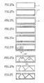
- FIG's. 5a to 5i are cross sections of the ink jet head in the respective fabrication steps thereof.
- a high density boron diffusion layer 2 is formed on a Si wafer 1, which is shown in Fig. 5a and has crystal face ⁇ 100 ⁇ , (FIG. 5b).
- the Si wafer 1 used here is 300 ⁇ m thick and the high density boron diffusion layer 2 has a thickness of 10 ⁇ m.
- a silicon oxide film 3 which is 2 ⁇ m thick and becomes an etching resistive mask, is formed on a surface of the Si wafer 1 by thermal oxidation of the latter as shown in FIG. 5c.
- the silicon oxide film is used as the etching resistive mask, that is, the resist film.
- the etching resistive mask is not limited to the silicon oxide film and any film such as a silicon nitride film or a metal film, which is durable against Si etching liquid, can be used therefor in the present invention including other embodiments to be described later.
- the resist is selectively removed by etching the silicon oxide film 3 with using buffered hydrofluoric acid solution, resulting in a nozzle pattern 110 and an ink pool pattern 113 such as shown in FIG. 5d and FIG. 6, respectively.
- the ink pool pattern 113 takes in the form of a plurality of thin grooves tilted with respect to an orientation flat by 45°, as shown in FIG. 6.
- Width of the groove is 1 ⁇ m and pitch of the pattern is 11 ⁇ m.
- the configuration of thin groove is not limited to the straight groove and any other configuration such as V-groove shown in FIG. 7 may be employed, provided that etchant can enter into the wafer through the groove to etch the inside of the wafer such that the wafer is hollowed out while leaving beams having width in the order of several microns.
- openings for forming the ink pools 103 and the nozzles 100 are formed in the high density boron diffusion layer 2 by dry-etching (FIG. 5e).
- the ink chamber 101 and the ink pool 103 are formed in the crystal face ⁇ 111 ⁇ by anisotropic wet-etching of Si, as shown in FIG. 5f.
- the wet-etching is performed in ethylenediamine pyrocatechol water (EPW) heated to about 100°C.
- EPW ethylenediamine pyrocatechol water
- beams each 10 ⁇ m wide are arranged on the ink pool 103 with an interval of 1 ⁇ m.
- the space (1 ⁇ m) between the beams arranged on the ink pool 103 is buried by a thermal oxide film newly formed on the Si wafer by thermal oxidation.
- the vibration plate is a thin silicon film.
- FIG. 8a An example of a fabrication method of the vibration plate will be described with reference to FIG. 8.
- the silicon oxide film 3 which is 5 ⁇ m thick and becomes the etching resistive mask, is formed on the surface of the Si wafer 1 as shown in FIG. 8a.
- the resist film is painted on the Si wafer 1 and a resist mask pattern defining the ink supply ports 102 is formed on the wafer surface by photolithography
- the resist is selectively removed by etching the silicon oxide film 3 with using buffered hydrofluoric acid solution, resulting in a nozzle pattern shown in FIG. 8c.
- the ink supply ports 102 are formed by dry-etching of silicon (FIG. 8d).
- the ink supply port 102 takes in the form of a groove having rectangular cross section, which is 100 ⁇ m long, 30 ⁇ m deep and 50 ⁇ m wide.
- the silicon oxide film 3 is removed by using hydrofluoric acid solution (FIG. 8e) and, then, the high density boron diffusion layer 2 having thickness of 10 ⁇ m is formed (FIG. 8f).
- the configuration of the boron diffusion layer depends upon the surface configuration of the wafer.
- a Pyrex glass 4 having thickness of 3 ⁇ m is deposited on the boron diffusion layer 2 by sputtering and is patterned by using hydrofluoric acid (FIG. 8g).
- the wafer is mated with the plate formed with the nozzles and the ink pools and electrostatic bonding is performed by applying a voltage of 400V at 400°C (FIG. 8h). In this electrostatic bonding, a negative voltage is applied to the side of the vibration plate (the side of the wafer on which the Pyrex glass is painted).
- the vibration plate is completed by removing a portion of the wafer, in which high density boron is not diffused, by etching it with using KOH solution, etc.
- the material of the vibration plate is not limited to silicon. Any other material such as glass, resin or metal may be used therefor, provided that it can efficiently transmit pressure to the ink chamber 101. Further, although the bonding of the parts is performed by electrostatic bonding method, similar effect can be obtained by using adhesive.
- the piezo electric element (not shown) is arranged in a predetermined position and wired suitably and the ink jet head is completed by connecting the wafer to the ink tank (not shown). Since it is possible to form the electrically conductive layer by forming the high density boron diffusion layer, it is possible to avoid electrostatic charging when the nozzles 100 are wiped.
- a high density boron diffusion layer 2 is formed on a Si wafer 1 shown in FIG. 9a and having crystal face ⁇ 100 ⁇ (FIG. 9b).
- the Si wafer 1 used here is 300 ⁇ m thick and the high density boron diffusion layer 2 has a thickness of 10 ⁇ m.
- a silicon oxide film 3 which is 2 ⁇ m thick and becomes an etching resistive mask, is formed on a surface of the Si wafer 1 by thermal oxidation thereof as shown in FIG. 9c.
- the ink supply ports 102 and the ink pools 103 is formed on the wafer surface by photolithography, the resist is selectively removed by etching the silicon oxide film 3 with using buffered hydrofluoric acid solution, resulting in a pattern such as shown in FIG. 9d.
- the pattern of the ink pools 103 takes in the form of a plurality of thin grooves tilted with respect to an orientation flat by 45° as shown in FIG. 6.
- Width of the groove is 1 ⁇ m and pitch of the pattern is 11 ⁇ m.
- the configuration of thin groove is not limited to the straight groove and any other configuration such as V-groove shown in FIG. 7 may be employed, provided that etchant can enter into the wafer through the groove to etch the inside of the wafer such that the wafer is hollowed out while leaving beams having width in the order of several microns.
- openings for forming the ink pools 103 and the nozzles 100 are formed in the high density boron diffusion layer 2 by dry-etching (FIG. 9e).
- the ink chambers 101, the ink supply ports 102 and the ink pools 103 are formed in the crystal face ⁇ 111 ⁇ by anisotropic wet-etching of Si, as shown in FIG. 9f.
- the wet-etching is performed in ethylenediamine pyrocatechol water (EPW) heated to about 100°C.
- EPW ethylenediamine pyrocatechol water
- beams each 10 ⁇ m wide are arranged on the ink pool 103 with an interval of 1 ⁇ m.
- the pattern formed on a lower surface of the substrate is shown in FIG. 10 and FIG. 11 shows it in more detail.
- the space (1 ⁇ m) between adjacent beams arranged on the ink pool 103 is buried by a thermal oxide film newly formed on the Si wafer by thermal oxidation.
- a vibration plate formed with the ink supply ports 102 is bonded to the Si wafer (FIG. 9i).
- the vibration plate having no ink supply ports is obtained.
- the electrostatic boding method is performed. That is, Pyrex glass 3 ⁇ m thick is deposited by sputtering and, after it is patterned by hydrofluoric acid, the vibration plate is mated with the plate formed with the nozzles and the ink pools. Then, a voltage of 400V is applied thereto at 400°C. Thereafter, the portion of the wafer, which has no high density boron diffused, is etched away with using KOH solution, etc.
- the piezo electric element (not shown) is arranged in a predetermined position and wired suitably and the ink jet head is completed by connecting the wafer to the ink tank (not shown).
- high density boron diffusion layers 2 are formed on both surfaces of a Si wafer 1 shown in FIG. 12a and having crystal face ⁇ 100 ⁇ (FIG. 12b).
- the Si wafer 1 used here is 300 ⁇ m thick and the high density boron diffusion layers 2 each has a thickness of 10 ⁇ m.
- a silicon oxide film 3 which is 2 ⁇ m thick and becomes an etching resistive mask, is formed on the surfaces of the Si wafer 1 by thermal oxidation thereof as shown in FIG. 12c.
- the resist is selectively removed by etching the silicon oxide film 3 with using buffered hydrofluoric acid solution, resulting in a pattern such as shown in FIG. 12d.
- the patterns 111 and 112 of the ink chambers 101 and the ink supply ports 102 take in the form of a plurality of thin grooves tilted with respect to an orientation flat by 45° as shown in FIG. 6.
- Width of the groove is 1 ⁇ m and pitch of the pattern is 11 ⁇ m.
- the configuration of thin groove is not limited to the straight groove and any other configuration such as V-groove shown in FIG. 7 may be employed, provided that etchant can enter into the wafer through the groove to etch the inside of the wafer such that the wafer is hollowed out while leaving beams having width in the order of several microns.
- the nozzles 100 and openings for forming the ink chambers 101, the ink supply ports 102 and the ink pools 103 are formed in the high density boron diffusion layer 2 by dry-etching (FIG. 12e).
- the ink chambers 101, the ink supply ports 102 and the ink pools 103 are formed in the crystal face ⁇ 111 ⁇ by anisotropic wet-etching of Si, as shown in FIG. 12f.
- the wet-etching is performed in ethylenediamine pyrocatechol water (EPW) heated to about 100°C.
- EPW ethylenediamine pyrocatechol water
- beams each 10 ⁇ m wide are arranged on the ink chambers 101, the ink supply ports 102 and the ink pool 103 with an interval of 1 ⁇ m.
- the space (1 ⁇ m) between adjacent beams arranged on the ink chambers 101, the ink supply ports 102 and the ink pool 103 is buried by a thermal oxide film newly formed on the Si wafer by thermal oxidation.
- the piezo electric element (not shown) is arranged in a predetermined position and wired suitably and the ink jet head is completed by connecting the wafer to the ink tank (not shown).
- FIG. 14 is a cross section of the ink jet head according to the second embodiment of the present invention taken along a line B-B' in FIG. 4.
- Nozzles 400 are formed on a surface of a substrate and in communication with ink chambers 201, respectively.
- the ink chamber 201 is constructed with four crystal face ⁇ 111 ⁇ 205 and has a square cross section.
- the faces constituting the crystal face ⁇ 111 ⁇ 105 are (-1 -1 -1), (-1 -1 1), (-1 1 1) and (-1 1 -1).
- the faces constituting the crystal face ⁇ 111 ⁇ 105 are (-1 -1 -1), (-1 -1 1), (1 -1 1) and (1 -1 -1) and, when the surface of the substrate is (001), the faces constituting the crystal face ⁇ 111 ⁇ 105 are (-1 -1 -1), (1 -1 -1), (1 1 -1) and (-1 1 -1).
- the ink chamber 201 and the ink pool 203 are connected each other through an ink supply port 202.
- the ink pool 203 is arranged adjacent to the ink chamber 201 and has a V groove structure constituted with two faces of the crystal face ⁇ 111 ⁇ 204.
- the faces constituting the crystal face ⁇ 111 ⁇ 204 are (-1 -1 -1) and (-1 1 1) or (-1 -1 1) and (-1 1 1).
- the faces constituting the crystal face ⁇ 111 ⁇ 204 are (-1 -1 -1) and (1 -1 1) or (1 -1 -1) and (-1 -1 1) and, when the surface of the silicon substrate is (001), the faces constituting the crystal face ⁇ 111 ⁇ 204 are (-1 -1 -1) and (1 1 -1) or (-1 1 -1) and (1 -1 -1).
- the ink chambers 201 and ink pools 203 Since it is possible to simultaneously form the ink chambers 201 and ink pools 203 from one of the surfaces of the substrate, it is possible to substantially reduce the process cost. Further, since it is possible to simultaneously pattern the ink chambers 201 and the ink pools 203 by photolithography, it is possible to reduce the positional error of the ink chambers 201 and the ink pools 203.
- a pressure generating mechanism 207 which is wired suitably (not shown), is arranged in a position on a thin film 206 corresponding to each of the ink chambers. Ink is supplied from an ink tank (not shown) to the ink pools 203.
- the piezo electric element is used as the pressure generating mechanism in this embodiment, it is possible to obtain similar effect by providing an ink heater in the thin film as the pressure generating mechanism.
- FIG's. 15a to 15h are cross sections of the ink jet head in the respective fabrication steps according to a first and second examples thereof.
- a high density boron diffusion layer 2 is formed on a Si wafer 1, which is shown in Fig. 15a and has crystal face ⁇ 100 ⁇ (FIG. 15b).
- the Si wafer 1 used here is 300 ⁇ m thick and the high density boron diffusion layer 2 has a thickness of 10 ⁇ m.
- a silicon oxide film 3 which is 2 ⁇ m thick and becomes an etching resistive mask, is formed on a surface of the wafer by thermal oxidation of the Si wafer 1 as shown in FIG. 15c.
- the resist is selectively removed by etching the silicon oxide film 3 with using buffered hydrofluoric acid solution, resulting in a pattern shown in FIG. 15d.
- the nozzles 200 are formed by dry-etching of the silicon (FIG. 15e).
- the ink chambers 201 and the ink pools 203 are formed in the crystal face ⁇ 111 ⁇ by anisotropic wet-etching of Si, as shown in FIG. 15f.
- the wet-etching is performed in ethylenediamine pyrocatechol water (EPW) heated to about 100°C.
- the silicon oxide film 3 is removed by using hydrofluoric acid solution (FIG. 15g) and the vibration plate formed with the ink supply ports 202 is bonded to the Si wafer 1 (FIG. 15h).
- the method for forming the vibration plate is the same as that mentioned with respect to the first embodiment.
- the ink supply ports 202 are formed in the substrate formed with the ink chambers 201 and the ink pools 203, by forming the pattern of the ink supply ports simultaneously at the time shown in FIG. 15d. In such case, since the vibration plate having no ink supply ports is to be used, the vibration plate may be fabricated without the steps shown in FIG's. 8b to 8e.
- the material of the vibration plate is not limited to silicon. Any other material such as glass, resin or metal may be used therefor, provided that it can efficiently transmit pressure to the ink chamber 201. Further, although the bonding of the parts is performed by electrostatic bonding method, similar effect can be obtained by using adhesive.
- the piezo electric element (not shown) is arranged in a predetermined position and wired suitably and the ink jet head is completed by connecting the wafer to the ink tank (not shown).
- high density boron diffusion layers 2 are formed on both surfaces of a Si wafer 1 shown in FIG. 16a and having orientations ⁇ 100 ⁇ faces (FIG. 16b).
- the Si wafer 1 used here is 300 ⁇ m thick and the high density boron diffusion layers 2 each has a thickness of 10 ⁇ m.
- a silicon oxide film 3 which is 2 ⁇ m thick and becomes an etching resistive mask, is formed on the surfaces of the Si wafer 1 by thermal oxidation thereof as shown in FIG. 12c.
- the resist is selectively removed by etching the silicon oxide film 3 with using buffered hydrofluoric acid solution, resulting in a pattern such as shown in FIG. 16d.
- the patterns 211, 212 and 213 of the ink chambers 201, the ink supply ports 202 and the ink pools 203 take in the form of a plurality of thin grooves tilted with respect to an orientation flat by 45° as shown in FIG. 17.
- Width of the groove is 1 ⁇ m and pitch of the pattern is 11 ⁇ m.
- the configuration of thin groove is not limited to the straight groove and any other configuration such as V-groove shown in FIG. 7 may be employed, provided that etchant can enter into the wafer through the groove to etch the inside of the wafer such that the wafer is hollowed out while leaving beams having width in the order of several microns.
- the nozzles 200 and openings for forming the ink chambers 201, the ink supply ports 202 and the ink pools 203 are formed in the high density boron diffusion layer 2 by dry-etching (FIG. 16e).
- the ink chambers 201, the ink supply ports 202 and the ink pools 203 are formed in the crystal face ⁇ 111 ⁇ by anisotropic wet-etching of Si, as shown in FIG. 16f.
- the wet-etching is performed in ethylenediamine pyrocatechol water (EPW) heated to about 100°C.
- EPW ethylenediamine pyrocatechol water
- beams each 10 ⁇ m wide are arranged on the ink chambers 201, the ink supply ports 202 and the ink pool 203 with an interval of 1 ⁇ m.
- the space (1 ⁇ m) between adjacent beams arranged on the ink chambers 201, the ink supply ports 202 and the ink pool 203 is buried by a thermal oxide film newly formed on the Si wafer by thermal oxidation.
- the piezo electric element (not shown) is arranged in a predetermined position and wired suitably and the ink jet head is completed by connecting the wafer to the ink tank (not shown).
- FIG. 18 is a cross section of the ink jet head according to a third embodiment of the present invention, taken along a line B-B' in FIG. 4.
- the surface of a substrate is any.
- Nozzles 300 are formed in a surface of the substrate and are in communication with ink chambers 301, respectively.
- the ink chamber 301 is constructed with face 305 perpendicular to the surface of the substrate and a horizontal cross section thereof is polygonal.
- the ink chamber 301 is in communication with the corresponding nozzle through at least one step portion 308.
- the horizontal cross section of the ink chamber may be circular.
- the ink chamber 301 and the ink pool 303 are connected each other through the ink supply port 302.
- the ink pool 303 is arranged adjacent to the ink chamber 301.
- the ink pool 303 is constructed with face 304 perpendicular to the surface of the substrate. Since the ink chamber 301 and the ink pool 303 can be partitioned by a partition wall perpendicular to the surface of the substrate, it is possible to reduce a distance between the ink chamber 301 and the ink pool 303. That is, the nozzles can be arranged at high density.
- the face formed by dry-etching is very smooth, the problem of void discharge and/or ink stagnation in the ink chamber 301 and/or the ink pool 303 do not occur.
- a pressure generating mechanism 307 having wiring (not shown) is arranged in a position on a thin film 306 corresponding to each of the ink chambers. Ink is supplied from an ink tank (not shown) to the ink pools 303. According to the experiments conducted by the present inventors, it has been confirmed that, when a voltage is applied to the pressure generating mechanism 307, ink jetting performance of the pressure generating mechanism 307 is similar to that obtained conventionally. Although the piezo electric element is used in this embodiment as the pressure generating mechanism, it is possible to obtain similar effect by providing an ink heater in the thin film as the pressure generating mechanism.
- FIG's. 19a to 19i are cross sections of the ink jet head in the respective fabrication steps according to a first and second fabrication methods.
- silicon nitride films 4 having thickness of 0.5 ⁇ m are formed (FIG. 19b) on both surfaces of a Si wafer 1, which is shown in Fig. 19a and is 300 ⁇ m thick.
- the silicon nitride film 4 is selectively removed by dry-etching, resulting in a pattern shown in FIG. 19c.
- a silicon oxide film 3 having thickness of 2.5 ⁇ m is formed on the surface, in which the pattern of the ink chambers 301 and the ink pools 303 are formed, by CVD, as shown in FIG. 19d.
- the silicon oxide film 3 is selectively etched away by buffered hydrofluoric acid solution, resulting in a pattern shown in FIG. 19e.
- a deep silicon etching (dry-etching) is performed from the surface of the wafer, on which the pattern of the ink chambers 301 and the ink pools 303 is formed, by ICP system. Since, in the same etching, selective etching ratio of silicon for the silicon oxide film 3 and the silicon nitride film 4 is about 100, the silicon nitride film 4 having thickness of 0.5 ⁇ m provided in the step shown in FIG. 19b is broken (portion shown by broken line in FIG. 19f) at the time when the step portion 50 ⁇ m high in the ink chamber 301 is formed.
- the etching of the pattern formed in the step shown in FIG. 19e is performed.
- the ink chambers 301 are etched while the step portions thereof are kept as they are.
- the etching down to a depth of 240 ⁇ m is performed (FIG. 19g).
- a resist is painted on the Si wafer 1 and a resist pattern for forming the nozzles 300 in the predetermined locations on the wafer surface is formed by photolithography, the silicon nitride film 4 and the Si wafer 1 are dry-etched to remove the resist, resulting in the nozzles 300 as shown in FIG. 19h.
- the silicon oxide film 3 is removed by using hydrofluoric acid solution and the vibration plate formed with the ink supply ports 302 is bonded to the Si wafer 1 (FIG. 19i).
- the method for forming the vibration plate is the same as that mentioned with respect to the first embodiment.
- the ink supply ports 302 are formed in the substrate formed with the ink chambers 301 and the ink pools 303, by adding the forming step of the pattern of the ink supply ports after the step shown in FIG. 19g. In such case, since the vibration plate having no ink supply ports is to be used, the vibration plate may be fabricated without the steps shown in FIG's. 8b to 8e.
- the material of the vibration plate is not limited to silicon. Any other material such as glass, resin or metal may be used therefor, provided that it can efficiently transmit pressure to the ink chamber 301. Further, although the bonding of the parts is performed by electrostatic bonding method, similar effect can be obtained by using adhesive.
- the piezo electric element (not shown) is arranged in a predetermined position and wired suitably and the ink jet head is completed by connecting the wafer to the ink tank (not shown).
- FIG. 21 is a cross section of the ink jet head according to the fourth embodiment of the present invention taken along a line B-B' in FIG. 3.
- Nozzles 400 are formed on a surface of a substrate and in communication with ink chambers 401, respectively.
- the ink chamber 401 is constructed with eight faces including four faces 405 and four faces 409 of crystal face ⁇ 111 ⁇ and has a square horizontal cross section.
- the faces 405 of the crystal face ⁇ 111 ⁇ are (-1 -1 -1), (-1 -1 1), (-1 1 1) and (-1 1 -1) and the faces 409 of the crystal face ⁇ 111 ⁇ are (1 1 1), (1 1 -1), (1 -1 -1) and ((1 -1 1).
- the faces 405 of the crystal face ⁇ 111 ⁇ are (-1 -1 -1), (-1 -1 1), (1 - 1 1) and (1 -1 -1) and the faces 409 of the crystal face ⁇ 111 ⁇ are (1 1 1), (-1 1 1), (-1 1 -1) and (1 1 -1).
- the faces 405 of the crystal face ⁇ 111 ⁇ are (-1 -1 -1), (1 -1 -1), (1 1 -1) and (-1 1 -1) and the faces 409 of the crystal face ⁇ 111 ⁇ are (1 1 1), (1 -1 1), (-1 -1 1) and (-1 1 1).
- the ink chamber 401 has a configuration that a cross sectional area thereof gradually increases from a level of the nozzle 400 and gradually decreases from a certain level below the level of the nozzle 400. Since portions of the ink chamber 401, at which wall faces constructing the ink chamber 401 are put together, are formed as obtuse angles, ejection of void is so good that ink stagnation does not occur.
- the ink chamber 401 and the ink pool 403 are connected each other through an ink supply port 402.
- the ink pool 403 is arranged adjacent to the ink chamber 401 and has a V grove structure constituted with two faces 404 of the crystal face ⁇ 111 ⁇ .
- the two faces 404 are (1 1 1) and (1 -1 -1) or (1 1 -1) and (1 -1 -1).
- the faces 404 are (1 1 1) and (-1 1 -1) or (-1 1 1) and (1 1 -1) and, when the surface of the silicon substrate is (001), the faces 404 are (1 11) and (-1 -1 1) or (1 -1 1) and (-1 1 1).
- either one of the two faces 404 of the crystal face ⁇ 111 ⁇ is substantially in parallel to a certain one of the faces 405 of the crystal face ⁇ 111 ⁇ constructing the ink chamber 401, it is possible to reduce the distance between the ink chamber 401 and the ink pool 403, that is, a high density arrangement of the ink chambers.
- the partition wall partitioning the ink chamber 401 from the ink pool 403 is in the crystal face ⁇ 111 ⁇ , it is possible to form the wall having high aspect ratio with high precision to thereby reduce the distance between the ink chamber 401 and the ink pool 403.
- this configuration allows the plate thickness to make larger compared with the configuration broaden toward the bottom, the workability such as handling, etc., is improved. Since a Si wafer having standard thickness can be used even when a 6" Si wafer is used, it is possible to restrict the cost (thickness of 300 ⁇ m is not standard for the 6" wafer).
- Apressure generating mechanism 407 wired (not shown) is arranged in a position on a thin film 406 corresponding to each of the ink chambers. Ink is supplied from an ink tank (not shown) to the ink pools 403. According to the experiments conducted by the present inventors, it has been confirmed that, when a voltage is applied to the pressure generating mechanism, ink jetting performance of the pressure generating mechanism 407 is similar to that obtained conventionally. Although the piezo electric element is used as the pressure generating mechanism in this embodiment, it is possible to obtain similar effect by providing an ink heater in the thin film as the pressure generating mechanism.
- FIG's. 22a to 22i are cross sections of the ink jet head in the respective fabrication steps according to a first and second examples thereof.
- a high density boron diffusion layer 2 is formed on a Si wafer 1 having a surface in crystal face (100) and shown in Fig. 22a (FIG. 22b).
- the Si wafer 1 used here is 485 ⁇ m thick and the high density boron diffusion layer 2 has a thickness of 10 ⁇ m.
- a silicon oxide film 3 which is 2 ⁇ m thick and becomes an etching resistive mask, is formed on a surface of the wafer by thermal oxidation of the Si wafer 1 as shown in FIG. 22c.
- the ink chambers 401 and the ink pools 403 is formed on the wafer surface by photolithography, the resist is selectively removed by etching the silicon oxide film 3 with using buffered hydrofluoric acid solution, resulting in a pattern shown in FIG. 22d.
- the pattern of the ink pool 403 takes in the form of a plurality of thin grooves tilted with respect to an orientation flat by 45° as mentioned previously.
- Width of the groove is 1 ⁇ m and pitch of the pattern is 11 ⁇ m.
- the configuration of thin groove is not limited to the straight groove and any other configuration such as V-groove may be employed, provided that etchant can enter into the wafer through the groove to etch the inside of the wafer such that the wafer is hollowed out while leaving beams having width in the order of several microns
- the nozzles 400 and openings for forming the ink pools 403 are formed by dry-etching of the silicon and deep openings for forming the ink chambers 401 are also formed by dry-etching of silicon (FIG. 22e).
- the ink chamber 401 such as shown in FIG.
- the formation of the ink chambers 401 is shown in FIG's. 23a to 23c and, since a portion immediately below the nozzle 400 protrudes, the etching rate is high.
- the ink chambers 401 and the ink pools 403 are formed in the crystal face ⁇ 111 ⁇ by anisotropic wet-etching of Si, as shown in FIG. 22f.
- the wet-etching is performed in ethylenediamine pyrocatechol water (EPW) heated to about 100°C.
- EPW ethylenediamine pyrocatechol water
- beams each 10 ⁇ m wide are juxtaposed on the ink pool 403 with an internal of 1 ⁇ m.
- the space (1 ⁇ m) between adjacent beams arranged on the ink pool 403 is buried by a thermal oxide film newly formed on the Si wafer by thermal oxidation.
- the vibration plate formed with the ink supply ports 402 is bonded to the Si wafer 1 (FIG. 22i).
- the method for forming the vibration plate is the same as that mentioned with respect to the first embodiment.
- the ink supply ports 402 are formed in the substrate formed with the ink chambers 401 and the ink pools 403, by forming the pattern of the ink supply ports simultaneously at the time shown in FIG. 22d. In such case, since the vibration plate having no ink supply port is to be used, the vibration plate may be fabricated without the steps shown in FIG's. 8b to 8e.
- the material of the vibration plate is not limited to silicon. Any other material such as glass, resin or metal may be used therefor, provided that it can efficiently transmit pressure to the ink chamber 201. Further, although the bonding of the parts is performed by electrostatic bonding method, similar effect can be obtained by using adhesive.
- the piezo electric element (not shown) is arranged in a predetermined position and wired suitably and the ink jet head is completed by connecting the wafer to the ink tank (not shown).
- high density boron diffusion layers 2 are formed on both surfaces of a Si wafer 1, which are in crystal face ⁇ 100 ⁇ (FIG. 24b).
- the Si wafer 1 used here is 485 ⁇ m thick and the high density boron diffusion layers 2 each has a thickness of 10 ⁇ m.
- a silicon oxide film 3 which is 2 ⁇ m thick and becomes an etching resistive mask, is formed on the surfaces of the Si wafer 1 by thermal oxidation thereof as shown in FIG. 24c.
- the resist is selectively removed by etching the silicon oxide film 3 with using buffered hydrofluoric acid solution, resulting in a pattern such as shown in FIG. 24d.
- the patterns of the ink chambers 401, the ink supply ports 402 and the ink pools 403 take in the form of a plurality of thin grooves tilted with respect to an orientation flat by 45° as shown in FIG. 13. Width of the groove is 1 ⁇ m and pitch of the pattern is 11 ⁇ m.
- the configuration of thin groove is not limited to the straight groove and any other configuration such as V-groove shown in FIG. 7 may be employed, provided that etchant can enter into the wafer through the groove to etch the inside of the wafer such that the wafer is hollowed out while leaving beams having width in the order of several microns.
- the nozzles 400 and openings for forming the ink chambers 401, the ink supply ports 402 and the ink pools 403 are formed in the high density boron diffusion layer 2 by dry-etching (FIG. 24e) and deep opening for forming the ink chambers 401 is also formed by dry-etching of silicon (FIG. 24f).
- FIG. 24e dry-etching
- FIG. 24f dry-etching of silicon
- the ink chambers 401, the ink supply ports 402 and the ink pools 403 are formed in the crystal face ⁇ 111 ⁇ by anisotropic wet-etching of Si, as shown in FIG. 24g.
- the wet-etching is performed in ethylenediamine pyrocatechol water (EPW) heated to about 100°C.
- EPW ethylenediamine pyrocatechol water
- beams each 10 ⁇ m wide are juxtaposed on the ink chambers 401, the ink supply ports 402 and the ink pools 403 with an internal of 1 ⁇ m.
- the space (1 ⁇ m) between adjacent beams arranged on the ink chambers 401, the ink supply ports 402 and the ink pool 403 is buried by a thermal oxide film newly formed on the Si wafer by thermal oxidation..
- the piezo electric element (not shown) is arranged in a predetermined position and wired suitably and the ink jet head is completed by connecting the wafer to the ink tank (not shown).
- FIG. 25 is a cross section of the ink jet head according to the fifth embodiment of the present invention taken along a line B-B' in FIG. 4.
- Nozzles 500 are formed on a surface of a substrate and in communication with ink chambers 501, respectively.
- the ink chamber 401 is constructed with eight crystal faces including four faces 505 and four faces 509 of the crystal face ⁇ 111 ⁇ and has a square horizontal cross section.
- the faces 505 are (-1 -1 -1), (-1 -1 1), (-1 1 1) and (-1 1 -1) and the faces 509 are (1 1 1), (1 1 -1), (1 -1 -1) and ((1 - 1 1).
- the faces 505 are (-1 -1 -1), (-1 - 1 1), (1 -1 1) and (1 -1 -1) and the faces 509 are (1 1 1), (-1 1 1), (-1 1 -1) and (1 1 -1).
- the faces 505 are (-1 -1 -1), (1 -1 -1), (1 1 -1) and (-1 1 -1) and the faces 509 are (1 1 1), (1 -1 1), (-1 -1 1) and (-1 1 1).
- the ink chamber 501 has a configuration that a cross sectional area thereof gradually increases from a level of the nozzle 500 and gradually decreases from a certain level below the level of the nozzle 500. Since portions of the ink chamber 501, at which wall faces constructing the ink chamber 501 are put together, are formed as obtuse angles, ejection of void is so good that ink stagnation does not occur.
- the ink chamber 501 and the ink pool 503 are connected each other through an ink supply port 502.
- the ink pool 503 is arranged adjacent to the ink chamber 501 and has a V grove structure constituted with two walls in two faces 504 of the crystal face ⁇ 111 ⁇ .
- the faces 504 are (-1 -1 -1) and (-1 1 1) or (-1 -1 1) and (-1 1 -1).
- the faces 504 are (-1 -1 -1) and (1 -1 1) or (1 -1 -1) and (-1 -1 1) and, when the surface of the silicon substrate is (001), the faces 504 are (-1 -1 -1) and (1 1 -1) or (-1 1 -1) and (1 -1 -1).
- either one of the two faces 504 is substantially in parallel to a certain one of the faces 509 constructing the ink chamber 401, it is possible to reduce the distance between the ink chamber 501 and the ink pool 503, to thereby make a high density arrangement of the ink chambers possible.
- the partition wall partitioning the ink chamber 501 from the ink pool 503 is in the crystal face ⁇ 111 ⁇ , it is possible to form the wall having high aspect ratio with high precision to thereby reduce the distance between the ink chamber 501 and the ink pool 503.
- this configuration can increase the plate thickness compared with the configuration broaden toward the bottom, the workability such as handling, etc., is improved. Since a Si wafer having standard thickness can be used even when a 6" Si wafer is used, it is possible to restrict the cost (thickness of 300 ⁇ m is not standard for the 6" wafer).
- the crystal face ⁇ 111 ⁇ formed by anisotropic wet-etching are very smooth, the problem of void discharge and/or ink stagnation in the ink chamber 501 and/or the ink pool 503 do not occur.
- a pressure generating mechanism 507 having wiring (not shown) is arranged in a position on a thin film 506 corresponding to each of the ink chambers. Ink is supplied from an ink tank (not shown) to the ink pools 503.
- FIG's. 26a to 26h are cross sections of the ink jet head in the respective fabrication steps according to a first and second examples thereof.
- a high density boron diffusion layer 2 is formed on a surface of a Si wafer 1, which is in crystal face ⁇ 100 ⁇ and shown in Fig. 26a (FIG. 26b).
- the Si wafer 1 used here is 485 ⁇ m thick and the high density boron diffusion layer 2 has a thickness of 10 ⁇ m.
- a silicon oxide film 3 which is 2 ⁇ m thick and becomes an etching resistive mask, is formed on a surface of the wafer by thermal oxidation of the Si wafer 1 as shown in FIG. 26c.
- the ink chambers 501 and the ink pools 503 is formed on the wafer surface by photolithography, the silicon oxide film 3 is selectively removed by etching with using buffered hydrofluoric acid solution, resulting in a pattern shown in FIG. 26d.
- the nozzles 500 are formed by dry-etching of silicon and deep openings for forming the ink chambers 501 is also formed by dry-etching of silicon (FIG. 26e).
- the ink chambers 501 and the ink pools 503 are formed in the crystal face ⁇ 111 ⁇ by anisotropic wet-etching of Si, as shown in FIG. 26f.
- the wet-etching is performed in ethylenediamine pyrocatechol water (EPW) heated to about 100°C.
- the silicon oxide film 3 is removed by using hydrofluoric acid solution (FIG. 26g) and the vibration plate formed with the ink supply ports 502 is bonded to the Si wafer 1 (FIG. 26h).
- the method for forming the vibration plate is the same as that mentioned with respect to the first embodiment.
- the ink supply ports 502 are formed in the substrate formed with the ink chambers 501 and the ink pools 503, by forming the pattern of the ink supply ports simultaneously at the time shown in FIG. 26d. In such case, since the vibration plate having no ink supply port is to be used, the vibration plate may be fabricated without the steps shown in FIG's. 8b to 8e.
- the material of the vibration plate is not limited to silicon. Any other material such as glass, resin or metal may be used therefor, provided that it can efficiently transmit pressure to the ink chamber 501. Further, although the bonding of the parts is performed by electrostatic bonding method, similar effect can be obtained by using adhesive.
- the piezo electric element (not shown) is arranged in a predetermined position and wired suitably and the ink jet head is completed by connecting the wafer to the ink tank (not shown).
- high density boron diffusion layers 2 are formed on both surfaces of a Si wafer 1 having crystal face ⁇ 100 ⁇ and shown in FIG. 27a (FIG. 27b).
- the Si wafer 1 used here is 300 ⁇ m thick and the high density boron diffusion layers 2 each has a thickness of 10 ⁇ m.
- the silicon oxide film 3 is selectively removed by etching with using buffered hydrofluoric acid solution, resulting in a pattern such as shown in FIG. 27d.
- the patterns of the ink chambers 501, the ink supply ports 502 and the ink pools 503 take in the form of a plurality of thin grooves tilted by 45° with respect to an orientation flat as shown in FIG. 13. Width of the groove is 1 ⁇ m and pitch of the pattern is 11 ⁇ m.
- the configuration of thin groove is not limited to the straight groove and any other configuration such as V-groove shown in FIG. 7 may be employed, provided that etchant can enter into the wafer through the groove to etch the inside of the wafer such that the wafer is hollowed out while leaving beams having width in the order of several microns.
- the nozzles 500 and openings for forming the ink chambers 501, the ink supply ports 502 and the ink pools 503 are formed in the high density boron diffusion layer 2 by dry-etching (FIG. 27e) and deep opening for forming the ink chambers 501 is also formed by dry-etching of silicon (FIG. 27f).
- the following equation must be satisfied: de + 1/2(d + di) ⁇ tan 54.7° > t - b
- d nozzle size
- di size of opening for dry-etching for forming the ink chamber
- de depth of opening for dry-etching for forming the ink chamber (except total thickness of silicon oxide film/high density boron diffusion layer)
- t thickness of the substrate
- b total thickness of the high density boron diffusion layer.
- the ink chambers 501, the ink supply ports 502 and the ink pools 503 are formed in the crystal face ⁇ 111 ⁇ by anisotropic wet-etching of Si, as shown in FIG. 27g.
- the wet-etching is performed in ethylenediamine pyrocatechol water (EPW) heated to about 100°C.
- EPW ethylenediamine pyrocatechol water
- beams each 10 ⁇ m wide are juxtaposed on the ink chambers 501, the ink supply ports 502 and the ink pools 503 with an internal of 1 ⁇ m.
- the space (1 ⁇ m) between adjacent beams arranged on the ink chambers 501, the ink supply ports 502 and the ink pool 503 is buried by a thermal oxide film newly formed on the Si wafer by thermal oxidation..
- the piezo electric element (not shown) is arranged in a predetermined position and wired suitably and the ink jet head is completed by connecting the wafer to the ink tank (not shown).
- an ink jet head includes nozzles and ink chambers, which are arranged in matrix. Cross sections of the nozzle 100, the ink chamber 101 and the ink pool 103 are the same as those described with reference to the first embodiment shown in FIG. 2.
- FIG. 28 is a view of the whole ink jet head when looked from a side thereof in which nozzles are not formed.
- the ink chambers, the ink pools (ink branch passages) and the common ink pool (ink main passage) are substantially the same as those in the embodiment shown in FIG. 1.
- FIG. 29 shows the angle of the main scan direction with respect to the line of the nozzles (or ink chambers) or the side direction of the ink pool, when the ink jet head is printing.
- the ink jet head comprises the nozzles 100 for jetting ink droplets, the ink chambers 101, which are provided correspondingly to the respective nozzles and in communication therewith, the ink pools 103 for supplying ink to the ink chambers 101, the ink supply ports 102 for connecting the ink chambers 101 to the ink pool 103 and the pressure generating mechanisms 107 for pressurizing the ink chambers 101, as shown in FIG. 2.
- the ink pool 103 forms a comb shaped ink passage such that a plurality of the ink pools 103 are jointed and connected to a common ink pool 108, which is connected to the ink tank (not shown).
- the nozzles 100 are arranged in a line and row matrix as shown in FIG. 28 and the line of nozzles (or ink chambers) makes a constant angle ⁇ with respect to the main scan direction of the head during the printing as shown in FIG. 29.
- the cross section of the ink chamber 101 is square as shown in FIG. 4 and one of the sides forming its opening is in parallel to the side of the ink pool 103. Further, the side of the ink pool 103 and the wall face (partition wall face) of the ink chamber 101 are in the crystal face ⁇ 111 ⁇ of the silicon substrate and a longitudinal axis of the ink pool is in parallel to the crystal face ⁇ 111 ⁇ .
- the extreme ends (extreme ends opposite to the common ink pool) of the nozzles 100 (or ink chambers 101) forming the lines are arranged on a straight line perpendicular to the main scan direction during the printing and the longitudinal axis of the common ink pool 108 to which the ink pools 103 are connected is in a direction perpendicular to the printing scan direction similarly to the row direction of the nozzles.
- the angle ⁇ between the line direction of the nozzles (or sides of the ink pools) and the printing scan direction and the resolution of the head will be described with reference to a case where the resolution N of the head is 300 dpi (or ppi), the nozzle pitch of the nozzles adjacent to the longitudinal direction of the ink pools 103 is 0.515 mm, the axis of the ink pool is tilted with respect to the printing scan direction by 9.46° and the nozzles positioned at the extreme ends are arranged on an axis tilted with respect to the crystal face ⁇ 111 ⁇ by 9.46°.
- the nozzles and the ink chambers are arranged in a 36 (lines) x 8 (rows) matrix and the line direction is tilted with respect to the main scan direction during printing by 9.466°
- the lateral and vertical pitches of the nozzles (ink chambers) are 0.15 mm and 0.6681 mm, respectively. Therefore, in one ink jet head, 288 dots are arranged in a width of 23.7055 mm in the row direction.
- the fabrication method of the ink jet head according to this embodiment is the same as that described with reference to the first embodiment. However, it is possible to perform the etching with high precision if the anisotropic etching is performed by facing the mask faces of the ink chambers arranged in the matrix and the corresponding ink pool mask face in parallel to the crystal face (crystal orientation [111]).
- the ink jet head Since, in this embodiment, it is possible to efficiently arrange the nozzles, the in chambers and the ink pools with high density by utilizing the crystal faces, it is possible to make the ink jet head compact. Further, in cutting the ink jet head such that an outer configuration thereof extends along the main scan direction, it is possible to minimize the residual amount of function of the nozzles and the ink pools, which is necessary to perform the printing. Therefore, it is possible to reduce the loss on the silicon substrate to thereby reduce the fabrication cost.
- the row direction of the nozzles is perpendicular to the printing direction, it is possible to jet ink droplets from the nozzles simultaneously in row direction. Therefore, the ink jetting control in the row direction is simpler compared with the case wherein the direction of nozzle rows is tilted with respect to the printing direction. Further, since the printing ends (printing start points on the left side of the printing sheet) are made aligned, the amount of movement of heads during printing is minimized.
- the nozzles and the ink pools are formed in one substrate, it is possible to improve the reliability of the head and the yield of parts to thereby realize the ink jet head having superior producibility. It is further possible to avoid electrostatic charging of the nozzles. Further, since the nozzles and the ink chambers can be arranged at high density, it is possible to make the high resolution ink jet head compact and to reduce the fabrication cost.
- FIG. 30 is a cross section of the ink jet head according to the seventh embodiment of the present invention taken along a line perpendicular to the line B-B' in FIG. 4.
- Nozzles 700 are formed on a surface of a substrate and in communication with ink chambers 701, respectively.
- the ink chamber 701 is constructed with four faces 704 of crystal face ⁇ 111 ⁇ and has a square cross section.
- the ink chamber 701 is connected to an ink pool (not shown) through an ink supply port (not shown).
- a bottom of the ink chamber 701, which is opposing to the nozzle 700, is a thin film 706, which is etching residue when the ink chamber 701 is etched.
- the thin film 706 contains silicon diffused with boron at high density and silicon oxide or silicon nitride. Since such thin film 706 can be formed without necessity of specific bonding step by an adhesive, the number of fabrication steps can be reduced and ejection of void is not influenced adversely by pressed out portion of adhesive.
- a wired piezo electric element 707 is arranged in a position of the thin film 706 corresponding to the chamber as the pressure generating mechanism and ink is supplied from an ink tank (not shown) to the ink pool. According to the experiments conducted by the present inventors by applying a voltage to the pressure generating mechanism 707, it has been confirmed that ink jetting performance of the pressure generating mechanism 707 is similar to that obtained conventionally. Although the piezo electric element is used as the pressure generating mechanism in this embodiment, it is possible to obtain similar effect by providing an ink heater in the thin film as the pressure generating mechanism.
- FIG's. 31a to 31h are cross sections of the ink jet head in the respective fabrication steps.
- a high density boron diffusion layer 2 is formed on both surfaces of a Si wafer 1 having crystal orientation [100] and shown in Fig. 31a (FIG. 31b).
- the Si wafer 1 used here is 300 ⁇ m thick and the high density boron diffusion layer 2 has a thickness of 10 ⁇ m.
- a silicon oxide film 3 which is 2 ⁇ m thick and becomes an etching resistive mask, is formed on a surface of the wafer by thermal oxidation of the Si wafer 1 as shown in FIG. 31c.
- the silicon oxide film is used as the etching resistive mask in this embodiment, the etching resistive mask is not limited to the silicon oxide film and any film formed of a material silicon nitride or metal, which is durable against an etchant for silicon. This is true for embodiments to be described later.
- the silicon oxide film 3 is selectively removed by etching with using buffered hydrofluoric acid solution, resulting in a pattern shown in FIG. 31d.
- the pattern of the ink chambers 701 is a thin groove pattern tilted with respect to the orientation flat by 45°. With of the groove is 1 ⁇ m and the pitch of the groove pattern is 11 ⁇ m.
- the configuration of thin groove is not limited to the straight groove and any other configuration such as V-groove shown in FIG.
- the nozzles 700 and openings for forming the ink chambers 701 are formed by dry-etching (FIG. 31e).
- the ink chambers 701 are formed in the crystal face ⁇ 111 ⁇ by anisotropic wet-etching of Si, as shown in FIG. 31f.
- the wet-etching is performed in ethylenediamine pyrocatechol water (EPW) heated to about 100°C.
- EPW ethylenediamine pyrocatechol water
- the space (1 ⁇ m) between adjacent beams arranged on the ink chambers 701 is buried by a thermal oxide film newly formed on the Si wafer by thermal oxidation.
- the piezo electric element (not shown) is arranged in a predetermined position and wired suitably and the ink jet head is completed by connecting the wafer to the ink tank (not shown).
- FIG. 32 is a cross section of the ink jet head according to the eighth embodiment of the present invention taken along a line perpendicular to the line B-B' in FIG. 3 or 4.
- Nozzles 800 are formed on a surface of a substrate and in communication with ink chambers 801, respectively.
- the ink chamber 801 is constructed with four faces 804 having crystal orientation [111] and has a square cross section.
- the ink chamber 801 is connected to an ink pool (not shown) through an ink supply port (not shown).
- a high density boron diffusion layer 806, which is provided as an etch stop layer, is used as a thin film for transmitting pressure. Since it is possible to form the thin film without any bonding with using an adhesive, the number of fabricating steps can be reduced and ejection of void is not influenced adversely by pressed out portion of adhesive.
- a wired piezo electric element 807 is arranged in a position of the high density boron diffusion layer 806 corresponding to the chamber as the pressure generating mechanism and ink is supplied from an ink tank (not shown) to the ink pool. According to the experiments conducted by the present inventors by applying a voltage to the pressure generating mechanism 807, it has been confirmed that ink jetting performance of the pressure generating mechanism 807 is similar to that obtained conventionally. Although the piezo electric element is used as the pressure generating mechanism in this embodiment, it is possible to obtain similar effect by providing an ink heater in the thin film as the pressure generating mechanism.
- FIG. 33 is a cross section of an ink chamber, which is a modification of the eighth embodiment shown in FIG. 32.
- the high density boron diffusion layer 806 is provided through a polysilicon layer 808.
- a fabrication method of the ink jet head according to this modification will be described with reference to FIG's. 34a to 34j, which are cross sections of the ink jet head in the respective fabrication steps.
- a polysilicon layer 811 is deposited on one surface of a Si wafer 1 having crystal orientation [100] shown in Fig. 34a (FIG. 34b).
- the Si wafer 1 used here is 300 ⁇ m thick and the polysilicon layer 811 has a thickness of 15 ⁇ m.
- high density boron diffusion layers 2 and 812 each 10 ⁇ m thick are formed on the both surfaces of the Si wafer 1, as shown in FIG. 34c.
- the silicon oxide film 3 is selectively removed by etching with using buffered hydrofluoric acid solution, resulting in a pattern shown in FIG. 34e.
- the nozzles 800 are formed by dry-etching (FIG. 34f).
- the following equation in order to form the ink chamber 801 such as shown in FIG. 34i, the following equation must be satisfied: de + 1/2 ⁇ d ⁇ tan 54.7° > t - b
- d nozzle size
- de depth of opening for dry-etching for forming the ink chamber (except total thickness of silicon oxide film/high density boron diffusion layer)
- t thickness of the substrate
- b is total thickness of the high density boron diffusion layer.
- FIG. 34g a space surrounded by crystal faces having crystal orientation [111] is obtained as shown in FIG. 34g.
- a bottom of the space reaches the polysilicon layer 811.
- the polysilicon layer 811 is etched laterally since the polysilicon has no crystal orientation. Protrusions appearing with the lateral etching are selectively etched (FIG. 34h) and, ultimately, flat faces having crystal orientation [111] appear (FIG. 34i), resulting in a desired polysilicon layer 808.
- the silicon oxide film 3 is removed by using hydrofluoric acid solution (FIG. 34j) and the piezo electric element (not shown) is arranged in a predetermined position and wired suitably and the ink jet head is completed by connecting the wafer to the ink tank (not shown).
- FIG. 35 is a cross section of an ink chamber, which is another modification of the eighth embodiment shown in FIG. 32.
- the high density boron diffusion layer 806 is provided through a SiO 2 layer 809.
- FIG's. 36a to 36j are cross sections of the ink jet head in the respective fabrication steps.
- a SOI (silicon-on-insulator) wafer having faces in crystal orientation [100] such as shown in FIG. 36a.
- the SOI wafer is composed of a silicon layer 821 having thickness of 300 ⁇ m, a silicon layer 823 having thickness of 10 ⁇ m and a SiO 2 layer 822 having thickness of 5 ⁇ m disposed between the silicon layers 821 and 823.
- High density boron diffusion layers 2 each 10 ⁇ m thick are formed on both surfaces of the SOI wafer, as shown in FIG. 36b.
- a silicon nitride film 4 which is 0.5 ⁇ m thick and becomes an etching resistive mask, is formed on the whole surface of the SOI wafer, as shown in FIG. 36c.
- a resist film is painted on the SOI wafer and a resist mask pattern defining the nozzles 800 is formed on the wafer surface by photolithography, the silicon nitride film 4 is selectively removed by dry-etching, resulting in a pattern shown in FIG. 36d.
- the nozzles 800 are formed by dry-etching (FIG. 36e).
- the following equation in order to form the ink chamber 801 such as shown in FIG. 36i, the following equation must be satisfied: de + 1/2 ⁇ d ⁇ tan 54.7° > t1 - b
- d nozzle size
- de depth of opening for dry-etching for forming the ink chamber (except total thickness of silicon oxide film/high density boron diffusion layer)
- t1 is thickness of the substrate on the side of the nozzles
- b is total thickness of the high density boron diffusion layer.
- the silicon nitride film 4 is removed by using phosphoric acid solution (FIG. 36j) and the piezo electric element (not shown) is arranged in a predetermined position and wired suitably and the ink jet head is completed by connecting the wafer to the ink tank (not shown).
- the high density boron diffusion layer 2 is electrically conductive and, therefore, it is possible to avoid electrostatic charging of the head when the nozzles 800 are wiped, etc.
- the bonding of the cover plate becomes unnecessary and the reliability of the head and the yield of parts thereof can be improved. Further, it is possible to avoid electrostatic charging of the opening portions of the nozzles.
Abstract
Description
- The present invention relates to an ink jet head for recording an image, etc., by jetting ink droplets to a recording medium and a fabrication method of the ink jet head.
- Main portions constituting an ink jet head are nozzles for jetting ink droplets, ink chambers provided below the respective nozzles, for pressuring ink therein to jet ink droplets through the nozzles, and ink pools for supplying ink to the ink chambers. Further, ink passages are provided between the ink pools and the ink chambers. An ink pressuring mechanism is provided in each of the ink chambers and a cover plate of the ink chamber exists between the pressuring mechanism and the ink chamber.
- Among the prior arts, JP H09-57981A and JP H04-312853A disclose structures in each of which nozzles and ink chambers are formed in one substrate. In each of the prior arts, the nozzles are provided in one face of a crystalline plate and the ink chambers forming tapered or bell-shaped spaces are provided below the nozzles. In each of JP H5-309835A and JP H6-31914A, ink chambers, ink pools and ink passages are formed in one substrate. Further, in JP H6-218932A, ink chambers and a cover plate are formed in one substrate.
- In one of the prior arts, the nozzles and the ink chambers are formed in one substrate and, thereafter, ink pools and the ink passages, which are formed in another substrate, are bonded to the one substrate. In another of the prior arts, the ink chambers, the ink pools and the ink passages are formed in one substrate and, thereafter, the nozzles formed in another substrate are connected thereto. In a further example of the prior arts, the ink chambers and the cover plate are formed in one substrate and, thereafter, opening portions of the nozzles, which are formed in another substrate, are bonded thereto.
- Therefore, in the prior arts, there may be a case where the peeling occurs in the bonded portions, so that there is a problem that it is impossible to maintain air-tightness of spaces. Further, the preciseness and producibility of the ink jet head is lowered by the required bonding or connecting steps.
- The present invention was made in view of the above mentioned circumstances and an object of the present invention is to provide an ink jet head having superior producibility, which is realized by improving the reliability and the yield of parts by forming nozzles, ink chambers, ink pools and ink passages, which are main portions of the ink jet head, in one substrate.
- Another object of the present invention is to provide an ink jet head capable of avoiding electrostatic charging of nozzle portions.
- Another object of the present invention is to provide an ink jet head in which the density of nozzles can be increased and whose outer size can be reduced.
- A further object of the present invention is to provide an ink jet head with which the number of ink jet heads, which are obtainable from a single substrate, can be increased and the cost of the ink jet head can be reduced.
- According to a first aspect of the present invention, an ink jet head comprises nozzles formed in a silicon substrate for jetting ink droplets, ink chambers formed in the silicon substrate and connected to the respective nozzles for pressurizing ink filling the ink chambers and ink pools for supplying ink to the ink chambers through partition walls, the partition wall being formed at a predetermined angle with respect to a surface of the silicon substrate. The ink pools are provided adjacent to the ink chambers through thin partition walls, respectively.
- The nozzles of the ink jet head extend perpendicularly to crystal face {100} of the silicon substrate. The ink chambers connected to the nozzles for pressurizing ink filling the ink chambers are formed as wall faces including crystal face {111} and wall faces of the ink pools provided adjacent to the ink chambers for supplying ink to the ink chambers are in crystal face {111}.
- In more detail, the ink jet head may have a structure including the nozzles formed in the silicon substrate and extending perpendicularly to a surface of the silicon substrate and the ink chambers formed in the silicon substrate and connected to the respective nozzles, for pressurizing ink filling the ink chambers. A cross section of the ink chamber is tapered toward the related nozzle. Further, the structure includes the ink pools each for supplying ink to a plurality of the ink chambers are connected to the ink chambers through the partition walls and a cross section of each ink pool is tapered in a direction which is reverse to the tapering of the ink chambers.
- In this structure, the tapering of the cross section of the ink chamber and the tapering of the cross section of the ink pool are opposite each other, so that it is possible to reduce the area occupied by the ink chamber and the related ink pool when they are provided adjacently each other.
- Alternatively, the ink jet head may have a structure including the nozzles formed in the silicon substrate and extending perpendicularly to the surface of the silicon substrate and the ink chambers formed in the silicon substrate and connected to the respective nozzles for pressurizing ink filling the ink chambers. Cross sections of the ink chamber and the ink pool are tapered with respect to the surface of the substrate in which the nozzles are formed.
- In each of the above mentioned structures of the ink jet head of the present invention, a portion of the ink chamber may be tapered in a reverse direction.
- Alternatively, the ink jet head may have a structure including the nozzles formed in the silicon substrate and extending perpendicularly to the surface of the silicon substrate and the ink chambers formed in the silicon substrate and connected to the respective nozzles, for pressurizing ink filling the ink chambers. The structure further includes the ink pools provided adjacent to the ink chambers, for supplying ink to the ink chambers and the wall faces of the ink chamber and the ink pool are formed substantially perpendicularly to the substrate. The diameter of the nozzle may be stepped such that the diameter thereof is reduced toward the nozzle opening.
- In each of these structures of the ink jet head of the present invention, it is preferable to form an ink supply port between an ink chamber and an ink pool or it is preferable to bond a cover plate formed with ink supply grooves each connecting the ink pool to the ink chamber to the substrate. Further, it is preferable to provide a pressure generating mechanism for pressurizing ink in an ink chamber on a bottom of the ink chamber.
- According to a second aspect of the present invention, a fabrication method of an ink jet head comprises the steps of forming a high density impurity diffusion layer on one surface of a silicon substrate, forming an etching resistive mask film on the one surface of the silicon substrate, forming opening portions in the etching resistive mask film at locations thereof corresponding to the ink chambers and the ink pools to be formed in the silicon substrate, forming the ink chambers and the ink pools by performing anisotropic etching of the substrate through the opening portions and closing open portions of the thus formed ink chambers and the ink pools.
- The step of forming the opening portions for forming the ink chambers and ink pools includes, for example, the step of forming periodic grooves. The step of closing the open portions of the ink chambers and the ink pools includes, for example, the step of oxidizing residual silicon on the open portions.
- The step of forming the ink chambers and the ink pools by anisotropic etching may include the step of forming ink supply ports between the ink chambers and the ink pools.
- The step of forming the ink chambers and the ink pools by anisotropic etching includes the step of forming ink supply ports between the ink chambers and the ink pools and may include the step of bonding a cover plate to the silicon substrate formed with the ink supply ports connecting the ink pools to the ink chambers.
- The step of closing the open portions of the ink chambers and the ink pools may include the step of bonding a cover plate formed with ink supply grooves connecting the ink pools to the ink chambers to the silicon substrate.
- The fabrication method may further include the step of providing a piezo electric element for applying jet pressure to ink within each ink chamber on a bottom of the ink chamber.
- According to this fabrication method, it is possible to form the ink chambers and the ink pools from one surface of the substrate.
- Alternatively, the fabrication method may comprise the steps of forming high density impurity diffusion layers on both surfaces of a silicon substrate, forming etching resistive mask films on the surfaces of the silicon substrate, forming opening portions in the etching resistive mask film on one surface of the substrate, in which nozzles are opened, at locations thereof corresponding to the ink pools and opening portions in the etching resistive mask film on the other surface of the substrate at locations thereof corresponding to the ink chambers, forming the ink chambers and the ink pools by performing anisotropic etching of the substrate through the opening portions, closing the thus formed open portions of the ink pools and closing open portions of the thus formed ink chambers.
- In this case, the step of forming the opening portions for forming the ink chambers and the ink pools includes, for example, the step of providing periodic grooves in the opening portions of the ink pools.
- Each of the steps of closing the open portions of the ink chambers and the ink pools includes, for example, the step of oxidizing residual silicon on the open portions of the ink pools.
- The step of forming the ink chambers and the ink pools by anisotropic etching may include the step of forming ink supply ports between the ink chambers and the ink pools.
- Alternatively, the step of forming the ink chambers and the ink pools by anisotropic etching includes the step of forming ink supply ports between the ink chambers and the ink pools and may include the step of bonding a cover plate to the silicon substrate formed with the ink supply ports connecting the ink pools to the ink chambers.
- The step of closing the open portions of the ink chambers and the ink pools may include the step of forming ink supply ports between the ink chambers and the ink pools and may include the step of bonding a cover plate to the silicon substrate formed with the ink supply ports connecting the ink pools to the ink chambers.
- The step of forming the ink chambers and the ink pools by anisotropic etching may include the step of forming ink supply ports between the ink chambers and the ink pools and the step of closing the open portions of the ink chambers and the ink pools may include the step of oxidizing residual silicon on the open portions of the ink chambers.
- The fabrication method preferably comprises the step of providing a piezo electric element for applying jet pressure to ink within each ink chamber on an opposite side of the ink chamber to the nozzle.
- According to this fabrication method, it is possible to form the ink chambers and the ink pools from both surfaces of the silicon substrate. Therefore, it is possible to provide the structure in which the tapering of the ink chamber and the tapering of the ink pool are opposite each other.
- Alternatively, the fabrication method comprises the steps of forming etching resistive protection films on both surfaces of a silicon substrate, forming opening portions in the etching resistive protection films on both surfaces of the silicon substrate at locations thereof corresponding to the ink chambers and the ink pools to be formed, for etching the ink chambers and the ink pools therethrough, forming the ink chambers and the ink pools to predetermined depths from one of the surfaces of the substrate, which is opposite to a surface in which the nozzles are to be opened, by dry-etching and closing the open portions of the ink pools and the ink chambers.
- The fabrication method further includes the step of forming the nozzles by dry-etching and, in the step of forming the ink chambers, each ink chamber can be formed such that an upper portion of the ink chamber is stepped.
- The step of forming the ink chambers and the ink pools includes the step of forming ink supply ports between the ink chambers and the ink pools and may include the step of bonding a cover plate to the silicon substrate formed with the ink supply ports connecting the ink pools to the ink chambers.
- The step of closing the open portions of the ink chambers and the ink pools may include the step of bonding a cover plate formed with the ink supply ports connecting the ink pools to the ink chambers to the silicon substrate.
- The fabrication method preferably comprises the step of providing a piezo electric element for applying jet pressure to ink within each ink chamber on an opposite side of the ink chamber to the nozzle.
- According to this fabrication method, it is possible to provide a structure in which the ink pools are provided adjacent to the ink chambers and the wall faces of the ink chamber and the ink pool are formed substantially perpendicularly to the substrate.
- Alternatively, the fabrication method comprises the steps of forming a high density impurity diffusion layer on one surface of a silicon substrate, forming an etching resistive mask films on the one surface of the silicon substrate, forming opening portions in the etching resistive mask film on the one surface of the silicon substrate at locations thereof corresponding to the ink chambers and the ink pools, forming the ink chambers and the ink pools by anisotropic etching of the substrate through the opening portions and closing the thus formed open portions of the ink chambers and the ink pools.
- The step of forming the opening portions for forming the ink chambers and the ink pools includes, for example, the step of providing periodic grooves in the silicon substrate.
- Each of the steps of closing the open portions of the ink chambers and the ink pools includes, for example, the step of oxidizing residual silicon on the open portions of the ink chambers and the ink pools.
- The step of forming the ink chambers and the ink pools by anisotropic etching may include the step of forming ink supply ports between the ink chambers and the ink pools.
- The step of forming the ink chambers and the ink pools by anisotropic etching includes the step of forming ink supply ports between the ink chambers and the ink pools and may include the step of bonding a cover plate to the silicon substrate formed with the ink supply ports connecting the ink pools to the ink chambers.
- The step of closing the open portions of the ink chambers and the ink pools may include the step of bonding a cover plate formed with ink supply grooves between the ink chambers and the ink pools to the silicon substrate.
- The fabrication method may include the step of providing a piezo electric element for applying jet pressure to ink within each ink chamber on an opposite side of the ink chamber to the nozzle.
- According to this fabrication method, it is possible to provide a structure of the ink chamber in which a portion of the ink chamber is tapered in an opposite direction.
- By providing the nozzles and the ink pools in one substrate in this manner, it is possible to realize an ink jet head having high producibility due to improved reliability of head and the yield of parts. Further, since an electrically conductive layer is formed on the nozzle by the high density impurity diffusion layer, it is possible to prevent electrostatic charging due to friction caused by wiping from occurring.
- According to another aspect of the present invention, an ink jet head is provided, in which nozzles are arranged in a matrix of lines tilted with respect to a main scan direction (printing direction) by a constant angle and rows orthogonal to the main scan direction and the line direction of the nozzle arrangement or a lengthwise direction of the ink pools is coincident with the crystal orientation of the substrate.
- That is, the ink jet head is featured by comprising a plurality of nozzles arranged in a matrix of a plurality of lines tilted with respect to a main scan direction by a constant angle and a plurality of rows orthogonal to the main scan lines, a plurality of ink chambers provided correspondingly to the respective nozzles and pressurizing ink filling them, a plurality of ink pools provided along the respective lines for supplying ink to the respective ink chambers, ink passages communicating the ink pools with the ink chambers and a pressure generating mechanism provided in each ink chamber for generating pressure therein, wherein at least the ink chambers and the ink pools are formed in a crystalline plate and sides of the ink pools forming a longitudinal direction is coincident with crystal orientation of the crystalline plate.
- The crystalline plate is a silicon substrate having a surface in crystal face {100} and the sides of the ink pools forming the longitudinal direction of the ink pools are preferably formed in crystal face {111}.
- The ink chamber takes in the form of a pyramid having crystal face {111} as wall faces with respect to the nozzle and, preferably, wall faces of the other sides of the ink pool are in parallel to the wall faces of the ink chamber and a cross section of the ink pool is reverse-tapered.
- Assuming that a required resolution is N(dpi (dot per inch) or ppi (pixel per inch)) and a pitch between nozzles, which are adjacent in the lengthwise direction of the ink pool, is L (mm), one of axes of the ink pool is tilted by = arcsin 25.4/N/L with respect to the main scan direction.
- It is preferable that the direction of the nozzle rows in extreme ends of the respective nozzle lines is arranged on an axis tilted with respect to the crystal orientation of the crystalline plate by = arcsin 25.4 /N/L.
- The ink pools formed along the nozzle lines are connected to a common ink pool and a lengthwise axis of the common ink pool is preferably tilted with respect to the main scan direction by = arcsin 25.4/N/L.
- An outer configuration of the ink jet head is constructed with four sides tilted with respect to the crystal orientation of the crystalline plate by = arcsin 25.4/N/L.
- Further, the ink jet head is preferably moved in parallel to or perpendicularly to the sides constituting the outer configuration thereof when a printing is performed.
- In such structure, the ink chambers and the ink pools are efficiently arranged in the ink jet head, so that it is possible to arrange the nozzles at high density to thereby make the ink jet head compact. Further, since it is possible to efficiently arrange a plurality of ink jet heads in one silicon substrate with minimum loss thereof and to cut it to separate the ink jet heads each other, it is possible to increase the number of ink jet heads obtainable from the silicon substrate to thereby reduce the cost of the ink jet head. Since the rows of the nozzles are arranged perpendicularly to the printing direction on a printing sheet, the amount of movement of the ink jet head during printing is small, so that it is possible to make a printing drive control simple.
- According another aspect of the present invention, an ink jet head comprises a substrate, nozzle opening portions provided in a surface of the substrate for jetting ink, ink chambers provided in the substrate and connected to the respective nozzle opening portions for pressurizing ink filling them and a pressure generating mechanism for applying pressure to ink in each ink chamber, the pressure generating mechanism being provided through a thinned substrate portions on an opposite surface of the substrate to the surface in which the nozzle opening portions are formed.
- That is, this ink jet head according to the present invention is featured by that the nozzle opening portions for jetting ink and the ink chambers connected to the opening portions for applying pressure to ink filling them are formed in the substrate and the thinned substrate portion is provided on the surface of the substrate opposite to the surface in which the opening portions are formed.
- In detail, the nozzle opening portions extending vertically of the substrate are formed in one surface of the substrate and the ink chamber connected to each nozzle opening portion for applying pressure to ink filling the ink chamber is provided in the substrate. A cross section of the ink chamber is tapered with respect to the nozzle opening portion and a bottom of the ink chamber is covered by a thinned portion of the substrate.
- In more detail, the nozzle opening portions are formed perpendicularly to crystal face {100} of the silicon substrate and the ink chamber connected to each nozzle opening portion for applying pressure to ink filling the same ink chamber is provided as a wall face in crystal face {111}. The ink chambers are covered by a residual portion of the silicon substrate on the other surface of the silicon substrate.
- In a concrete structure, the nozzle opening portions extending vertically of the silicon substrate are formed in one surface of the silicon substrate and the ink chamber connected to each nozzle opening portion for applying pressure to ink filling the same ink chamber is provided in the silicon substrate. The cross section of the ink chamber is tapered toward the nozzle opening portion by etching and the bottom of the ink chamber is covered by thinned etching residue of the silicon substrate.
- The thin etching residue of the silicon substrate is formed by oxidizing silicon in the form of slits or formed by a high density impunity diffusion layer, which is resistive to etching.
- Alternatively, a thin polysilicon film is formed on one surface of the silicon substrate, the nozzle opening portions are formed vertically of the silicon substrate from the other surface of the silicon substrate, the ink chambers, which are connected to the respective nozzle opening portions for applying pressure to ink filling the ink chambers, are provided. The cross section of the ink chamber is tapered toward the nozzle opening portion and the bottom surface of the ink chamber is covered by etching residue of the thin polysilicon film.
- Alternatively, a silicon film or a thin polysilicon film is formed on one surface of the silicon substrate through a silicon oxide film, the nozzle opening portions are formed vertically of the silicon substrate from the other surface of the silicon substrate, the ink chambers, which are connected to the respective nozzle opening portions, are provided. The cross section of the ink chamber is tapered toward the nozzle opening portion by etching and the bottom surface of the ink chamber is covered by etching residue of the silicon film or the thin polysilicon film.
- In such structure, it is preferable to provide the ink pool for supplying ink to the ink chambers through ink supply ports adjacent to the ink chambers.
- According to another aspect of the present invention, a fabrication method of an ink jet head comprises the steps of forming a high density impurity diffusion layer on one surface of the silicon substrate, forming an etching resistive mask film on the one surface of the silicon substrate, providing etching openings in locations of the etching resistive mask film on the one surface of the silicon substrate, at which the ink chambers are to be formed, forming the ink chambers from the one surface by anisotropic etching and closing the opening portions of the thus formed ink chambers.
- The step of forming the opening portions for forming the ink chambers may include the step of forming periodic grooves. The step of closing the open portions of the ink chambers may include the step of oxidizing etching residue of silicon on the open portions.
- Alternatively, the fabrication method comprises the steps of forming a high density impurity diffusion layer on one surface of the silicon substrate, forming an etching resistive mask film on the surface of the silicon substrate, forming nozzle opening portions from the other surface of the silicon substrate and forming openings to a depth enough to form the ink chambers, by dry-etching, and forming the ink chambers through the nozzle opening portions by anisotropic etching such that the high density impurity diffusion layer is left on the other surface of the silicon substrate.
- Alternatively, the fabrication method comprises the steps of forming a polysilicon film on one surface of the silicon substrate, forming a high density impurity diffusion layer on the polysilicon film, forming nozzle opening portions from the other surface of the silicon substrate and forming openings to a depth enough to form the ink chambers, by dry-etching, and forming the ink chambers through the nozzle opening portions by anisotropic etching such that the high density impurity diffusion layer is left on the other surface of the silicon substrate.
- Alternatively, the fabrication method of the ink jet head comprises the steps of forming a silicon film or a polysilicon film on one surface of the silicon substrate through a silicon oxide film, forming a high density impurity diffusion layer on the silicon film or the polysilicon film and the other surface of the silicon substrate, forming nozzle opening portions from the other surface of the silicon substrate and forming openings to a depth enough to form the ink chambers, by dry-etching, and forming the ink chambers through the nozzle opening portions by anisotropic etching such that the high density impurity diffusion layer on the silicon film or the polysilicon film is left on the one surface of the silicon substrate
- In this case, the crystal orientation of the surfaces of the silicon substrate is [100] and the anisotropic etching is preferably performed such that crystal orientation of the wall faces of the ink chamber becomes [111]. Further, the high density impurity diffusion layer is preferably a high density boron diffusion layer.
- With such structure, the bonding of the cover plate to the substrate becomes unnecessary, so that the ink jet head capable of improving the reliability and capable of improving the yield of parts can be realized. Further, when an electrically conductive layer is formed in the nozzle opening portion by the high density impurity diffusion layer, electrostatic charging can be avoided against friction by such as wiping.
- Preferred embodiments of the present invention will be described with reference to the accompanying drawings, in which:
- FIG. 1 is a plan view showing a whole ink jet head schematically;
- FIG. 2 is a cross section of an ink jet head according to a first embodiment of the present invention;
- FIG. 3 shows, in an enlarged scale, a portion of the ink jet head according to the first embodiment as well as the fourth embodiment of the present invention;
- FIG. 4 shows, in an enlarged scale, a portion of the ink jet head according to the second, the third and the fifth embodiments of the present invention;
- FIG's. 5a to 5i are cross sections showing fabrication steps of a first fabrication method for fabricating the ink jet head according to the first embodiment of the present invention;
- FIG. 6 shows a pattern of straight lined ink pools;
- FIG. 7 shows a pattern of V-shaped ink pools;
- FIG's. 8a to 8h illustrate a fabrication method for fabricating a vibration plate;
- FIG's. 9a to 9i are cross sections showing fabrication steps of a second fabrication method for fabricating the ink jet head according to the first embodiment of the present invention;
- FIG. 10 shows a pattern of a lower surface of a substrate in the second fabrication method;
- FIG. 11 shows a state of the lower surface of the substrate in the second fabrication method;
- FIG's. 12a to 12h are cross sections showing fabrication steps of a third fabrication method for fabricating the ink jet head according to the first embodiment of the present invention;
- FIG. 13 shows a pattern for forming ink chambers and ink supply ports in the third fabrication method;
- FIG. 14 is a cross section of an ink jet head according to a second embodiment of the present invention;
- FIG's. 15a to 15h are cross sections of the ink jet head according to the second embodiment, showing a first and second fabrication methods;
- FIG's. 16a to 16h are cross sections of the ink jet head according to the second embodiment, showing a third fabrication method;
- FIG. 17 shows patterns of ink chambers, ink supply ports and ink pools in the third fabrication method for fabricating the ink jet head according to the second embodiment of the present invention;
- FIG. 18 is a cross section of an ink jet head according to a third embodiment of the present invention;
- FIG's. 19a to 19i are cross sections showing fabrication steps of a first and second fabrication methods for fabricating the ink jet head according to the third embodiment of the present invention;
- FIG. 20 is a dimensional figure of a portion of the ink jet head according to the third embodiment of the present invention, which is in the vicinity of a nozzle thereof;
- FIG. 21 is a cross section of an ink jet head according to a fourth embodiment of the present invention;
- FIG's. 22a to 22i are cross sections showing fabrication steps of a first and second fabrication methods for fabricating the ink jet head according to the fourth embodiment of the present invention;
- FIG's. 23a to 23c are cross sections of the ink jet head according to the fourth embodiment of the present invention, illustrating the formation of the ink chambers;
- FIG's. 24a to 24i are cross sections showing fabrication steps of a third fabrication method for fabricating the ink jet head according to the fourth embodiment of the present invention;
- FIG. 25 is a cross section of an ink jet head according to a fifth embodiment of the present invention;
- FIG's. 26a to 26h are cross sections showing fabrication steps of a first and second fabrication methods for fabricating the ink jet head according to the fifth embodiment of the present invention;
- FIG's. 27a to 27i are cross sections showing fabrication steps of a third fabrication method for fabricating the ink jet head according to the fifth embodiment of the present invention;
- FIG. 28 shows a whole ink jet head according to a sixth embodiment of the present invention;
- FIG. 29 is a figure, showing an angle of a line of ink pools or ink chambers with respect to a main scan direction;
- FIG. 30 is a cross section of an ink jet head according to a seventh embodiment of the present invention;
- FIG's. 31a to 31h are cross sections of the ink jet head of the first embodiment of the present invention, showing fabrication steps thereof;
- FIG. 32 is a cross section of an ink jet head according to an eighth embodiment of the present invention;
- FIG. 33 is a cross section of a polysilicon vibration plate head, which is a modification of the eighth embodiment of the present invention;
- FIG's. 34a to 34j are cross sections of the polysilicon vibration plate head, showing the fabrication steps of the modification;
- FIG. 35 is a cross section of an SOI head, which is another modification of the eighth embodiment of the present invention; and
- FIG's. 36a to 36j are cross sections of the SOI head, showing the fabrication steps thereof.
-
- FIG. 1 is a plan view showing a whole ink jet head according to a first embodiment of the present invention, which includes a plurality of pairs 11 each of a nozzle and an ink chamber and a plurality of ink pools 12. In FIG. 1, the nozzle/ink chamber pairs llfor jetting ink are arranged adjacent to each other and the ink chambers are connected to a common ink pool 12 to form a unit matrix. FIG. 1 shows an example, which includes four unit matrices. In the unit matrix, the ink chambers are connected to a branch ink supply passage 13 and a plurality of the branch ink supply passages 13 are connected to a main ink supply passage 14, which is connected to an ink tank (not shown). FIG. 3 shows a portion of the unit matrix in a first and fourth embodiments of the present ink jet head in an enlarged scale and FIG. 4 shows a portion of the unit matrix in a second, third and fifth embodiments of the present invention in an enlarged scale. Portions shown by dotted lines in FIG. 3 show an ink pool on the nozzle side.
- FIG. 2 is a cross section of the ink jet head according to the first embodiment of the present invention taken along a line B-B' in FIG. 3, showing a structural feature of the first embodiment, and FIG. 3 is a plan view of the nozzles on a plane taken along a line A-A' in FIG. 2, when looked from the side of a pressure generating mechanism, in which nozzles are not provided. In the first embodiment of the present invention, the
nozzle 100, theink chamber 101 and theink pool 103 are formed in one substrate, as shown in FIG. 2. Theink chamber 101 has a tapered configuration and an upper end of theink chamber 101 is connected to thenozzle 100. Theink pool 103 has a reverse-tapered configuration with respect to the ink chamber. In this embodiment, the substrate is a silicon (Si) substrate, in which theink chamber 101 is constructed with four crystal faces {111} 105 and provides a square configuration in horizontal cross section as shown in FIG. 3. When the surface of the silicon substrate is face (100), the crystal face {111} 105 include (-1 -1 -1), (-1 -1 1), (-1 1 1) and (-1 1 -1). When the surface of the silicon substrate is (010), the crystal face {111} 105 include (-1 -1 -1), (-1 -1 1), (1 -1 1) and (1 -1 -1) and, when the surface of the substrate is (001), the crystal face {111} 105 include (-1 - 1 -1), (1 -1 -1), (1 1 -1) and (-1 1 -1). - The
ink chamber 101 and theink pool 103 are connected each other through anink supply port 102. Theink pool 103 is arranged adjacent to theink chamber 101 and has a V grove structure constituted with two crystal face {111} 104. When the surface of the silicon substrate is (100), the crystal face {111} 104 include (1 1 1) and (1 -1 -1) or (1 1 -1) and (1 -1 1). When the surface of the silicon substrate is (010), the crystal face {111} 104 include (1 1 1) and (-1 1 - 1) or (-1 1 1) and (1 1 -1) and, when the surface of the silicon substrate is (001), the crystal face {111} 104 include (1 1 1) and (-1 -1 1) or (1 -1 1) and (-1 1 1). - Since any one of the two crystal face {111} 104 is substantially in parallel to a certain face of the four crystal face {111} 105 constituting the
ink chamber 101, it is possible to reduce a gap between theink chamber 101 and theink pool 103, that is, to arrange them at high density. - Since a partition wall separating the
ink chamber 101 from theink pool 103 is constituted with crystal face {111}, it is possible to form the wall having high aspect ratio precisely to thereby make the gap between theink chamber 101 and theink pool 103 extremely small. - Since the crystal face {111} provided by anisotropic wet-etching are very smooth, the problem of void discharge and/or ink stagnation in the
ink chamber 101 and/or theink pool 103 do not occur. - Apiezo
electric element 107 having a wiring (not shown) is arranged in a position in athin film 106, which forms a bottom of the nozzle/ink chamber pair 11, corresponding to theink chamber 101 as the pressure generating mechanism. Ink is supplied from an ink tank (not shown) to the ink pools 103. According to the experiments conducted by the present inventors, it has been confirmed that ink jetting performance of the piezoelectric element 107 when a voltage is applied to the piezoelectric element 107 is similar to that obtained conventionally. In this embodiment, it is possible to obtain similar effect by providing an ink heater in the thin film as the pressure generating mechanism, instead of the piezo electric element. - Now, a fabrication method of the ink jet head according to the first embodiment of the present invention will be described with reference to FIG's. 5a to 5i, which are cross sections of the ink jet head in the respective fabrication steps thereof. First, a high density
boron diffusion layer 2 is formed on aSi wafer 1, which is shown in Fig. 5a and has crystal face {100}, (FIG. 5b). TheSi wafer 1 used here is 300µm thick and the high densityboron diffusion layer 2 has a thickness of 10µm. - Next, a
silicon oxide film 3, which is 2µm thick and becomes an etching resistive mask, is formed on a surface of theSi wafer 1 by thermal oxidation of the latter as shown in FIG. 5c. In this embodiment, the silicon oxide film is used as the etching resistive mask, that is, the resist film. However, the etching resistive mask is not limited to the silicon oxide film and any film such as a silicon nitride film or a metal film, which is durable against Si etching liquid, can be used therefor in the present invention including other embodiments to be described later. - Next, after a resist film is painted on the
Si wafer 1 and a resist mask pattern defining thenozzles 100 and the ink pools 103 is formed on the wafer surface by photolithography, the resist is selectively removed by etching thesilicon oxide film 3 with using buffered hydrofluoric acid solution, resulting in anozzle pattern 110 and anink pool pattern 113 such as shown in FIG. 5d and FIG. 6, respectively. - In this case, the
ink pool pattern 113 takes in the form of a plurality of thin grooves tilted with respect to an orientation flat by 45°, as shown in FIG. 6. Width of the groove is 1µm and pitch of the pattern is 11µm. The configuration of thin groove is not limited to the straight groove and any other configuration such as V-groove shown in FIG. 7 may be employed, provided that etchant can enter into the wafer through the groove to etch the inside of the wafer such that the wafer is hollowed out while leaving beams having width in the order of several microns. Thereafter, openings for forming the ink pools 103 and thenozzles 100 are formed in the high densityboron diffusion layer 2 by dry-etching (FIG. 5e). - Next, the
ink chamber 101 and theink pool 103 are formed in the crystal face {111} by anisotropic wet-etching of Si, as shown in FIG. 5f. The wet-etching is performed in ethylenediamine pyrocatechol water (EPW) heated to about 100°C. At a time when the anisotropic wet-etching is completed, beams each 10µm wide are arranged on theink pool 103 with an interval of 1µm. - Thereafter, the
silicon oxide film 3 is removed by using hydrofluoric acid solution (FIG. 5g) and theSi wafer 1 is thermal-oxidized again at 1100°C for about 3 hours in atmosphere of H2 : O2 = 1 : 1 (FIG. 5h). The space (1µm) between the beams arranged on theink pool 103 is buried by a thermal oxide film newly formed on the Si wafer by thermal oxidation. - Thereafter, a vibration plate formed with the
ink supply ports 102 is bonded to the Si wafer (FIG. 5i). In this embodiment, the vibration plate is a thin silicon film. An example of a fabrication method of the vibration plate will be described with reference to FIG. 8. First, thesilicon oxide film 3, which is 5µm thick and becomes the etching resistive mask, is formed on the surface of theSi wafer 1 as shown in FIG. 8a. - Then, after the resist film is painted on the
Si wafer 1 and a resist mask pattern defining theink supply ports 102 is formed on the wafer surface by photolithography, the resist is selectively removed by etching thesilicon oxide film 3 with using buffered hydrofluoric acid solution, resulting in a nozzle pattern shown in FIG. 8c. Thereafter, theink supply ports 102 are formed by dry-etching of silicon (FIG. 8d). Theink supply port 102 takes in the form of a groove having rectangular cross section, which is 100µm long, 30µm deep and 50µm wide. - Thereafter, the
silicon oxide film 3 is removed by using hydrofluoric acid solution (FIG. 8e) and, then, the high densityboron diffusion layer 2 having thickness of 10µm is formed (FIG. 8f). In this case, the configuration of the boron diffusion layer depends upon the surface configuration of the wafer. - Thereafter, a
Pyrex glass 4 having thickness of 3µm is deposited on theboron diffusion layer 2 by sputtering and is patterned by using hydrofluoric acid (FIG. 8g). The wafer is mated with the plate formed with the nozzles and the ink pools and electrostatic bonding is performed by applying a voltage of 400V at 400°C (FIG. 8h). In this electrostatic bonding, a negative voltage is applied to the side of the vibration plate (the side of the wafer on which the Pyrex glass is painted). - The vibration plate is completed by removing a portion of the wafer, in which high density boron is not diffused, by etching it with using KOH solution, etc.
- The material of the vibration plate is not limited to silicon. Any other material such as glass, resin or metal may be used therefor, provided that it can efficiently transmit pressure to the
ink chamber 101. Further, although the bonding of the parts is performed by electrostatic bonding method, similar effect can be obtained by using adhesive. - Finally, the piezo electric element (not shown) is arranged in a predetermined position and wired suitably and the ink jet head is completed by connecting the wafer to the ink tank (not shown). Since it is possible to form the electrically conductive layer by forming the high density boron diffusion layer, it is possible to avoid electrostatic charging when the
nozzles 100 are wiped. - Next, a second fabrication method of the ink jet head according to the first embodiment of the present invention will be described with reference to FIG's. 9a to 9i. First, a high density
boron diffusion layer 2 is formed on aSi wafer 1 shown in FIG. 9a and having crystal face {100} (FIG. 9b). TheSi wafer 1 used here is 300µm thick and the high densityboron diffusion layer 2 has a thickness of 10µm. - Next, a
silicon oxide film 3, which is 2µm thick and becomes an etching resistive mask, is formed on a surface of theSi wafer 1 by thermal oxidation thereof as shown in FIG. 9c. - Next, after a resist film is painted on the
Si wafer 1 and a resist mask pattern defining thenozzles 100, theink supply ports 102 and the ink pools 103 is formed on the wafer surface by photolithography, the resist is selectively removed by etching thesilicon oxide film 3 with using buffered hydrofluoric acid solution, resulting in a pattern such as shown in FIG. 9d. - In this case, the pattern of the ink pools 103 takes in the form of a plurality of thin grooves tilted with respect to an orientation flat by 45° as shown in FIG. 6. Width of the groove is 1µm and pitch of the pattern is 11µm. The configuration of thin groove is not limited to the straight groove and any other configuration such as V-groove shown in FIG. 7 may be employed, provided that etchant can enter into the wafer through the groove to etch the inside of the wafer such that the wafer is hollowed out while leaving beams having width in the order of several microns.
- Thereafter, openings for forming the ink pools 103 and the
nozzles 100 are formed in the high densityboron diffusion layer 2 by dry-etching (FIG. 9e). - Next, the
ink chambers 101, theink supply ports 102 and the ink pools 103 are formed in the crystal face {111} by anisotropic wet-etching of Si, as shown in FIG. 9f. The wet-etching is performed in ethylenediamine pyrocatechol water (EPW) heated to about 100°C. At a time when the anisotropic wet-etching is completed, beams each 10µm wide are arranged on theink pool 103 with an interval of 1µm. The pattern formed on a lower surface of the substrate is shown in FIG. 10 and FIG. 11 shows it in more detail. - Thereafter, the
silicon oxide film 3 is removed by using hydrofluoric acid solution (FIG. 9g) and theSi wafer 1 is thermal-oxidized again at 1100°C for about 3 hours in atmosphere of H2 : O2 = 1 : 1 (FIG. 9h). The space (1µm) between adjacent beams arranged on theink pool 103 is buried by a thermal oxide film newly formed on the Si wafer by thermal oxidation. - Thereafter, a vibration plate formed with the
ink supply ports 102 is bonded to the Si wafer (FIG. 9i). In this case, by eliminating the steps shown in FIG's. 8b to 8e, the vibration plate having no ink supply ports is obtained. As described previously, the electrostatic boding method is performed. That is, Pyrex glass 3µm thick is deposited by sputtering and, after it is patterned by hydrofluoric acid, the vibration plate is mated with the plate formed with the nozzles and the ink pools. Then, a voltage of 400V is applied thereto at 400°C. Thereafter, the portion of the wafer, which has no high density boron diffused, is etched away with using KOH solution, etc. - Finally, the piezo electric element (not shown) is arranged in a predetermined position and wired suitably and the ink jet head is completed by connecting the wafer to the ink tank (not shown).
- Next, a third fabrication method of the ink jet head according to the first embodiment of the present invention will be described with reference to FIG's. 12a to 12h. First, high density boron diffusion layers 2 are formed on both surfaces of a
Si wafer 1 shown in FIG. 12a and having crystal face {100} (FIG. 12b). TheSi wafer 1 used here is 300µm thick and the high density boron diffusion layers 2 each has a thickness of 10µm. - Next, a
silicon oxide film 3, which is 2µm thick and becomes an etching resistive mask, is formed on the surfaces of theSi wafer 1 by thermal oxidation thereof as shown in FIG. 12c. - Next, after a resist film is painted on the
Si wafer 1 and a resist mask pattern defining thenozzles 100, theink chambers 101, theink supply ports 102 and the ink pools 103 is formed on the wafer surface by photolithography, the resist is selectively removed by etching thesilicon oxide film 3 with using buffered hydrofluoric acid solution, resulting in a pattern such as shown in FIG. 12d. - In this case, the
patterns ink chambers 101 and theink supply ports 102 take in the form of a plurality of thin grooves tilted with respect to an orientation flat by 45° as shown in FIG. 6. Width of the groove is 1µm and pitch of the pattern is 11µm. The configuration of thin groove is not limited to the straight groove and any other configuration such as V-groove shown in FIG. 7 may be employed, provided that etchant can enter into the wafer through the groove to etch the inside of the wafer such that the wafer is hollowed out while leaving beams having width in the order of several microns. - Thereafter, the
nozzles 100 and openings for forming theink chambers 101, theink supply ports 102 and the ink pools 103 are formed in the high densityboron diffusion layer 2 by dry-etching (FIG. 12e). - Next, the
ink chambers 101, theink supply ports 102 and the ink pools 103 are formed in the crystal face {111} by anisotropic wet-etching of Si, as shown in FIG. 12f. The wet-etching is performed in ethylenediamine pyrocatechol water (EPW) heated to about 100°C. At a time when the anisotropic wet-etching is completed, beams each 10µm wide are arranged on theink chambers 101, theink supply ports 102 and theink pool 103 with an interval of 1µm. - Thereafter, the
silicon oxide film 3 is removed by using hydrofluoric acid solution (FIG. 12g) and theSi wafer 1 is thermal-oxidized again at 1100°C for about 3 hours in atmosphere of H2 : O2 = 1 : 1 (FIG. 12h). The space (1µm) between adjacent beams arranged on theink chambers 101, theink supply ports 102 and theink pool 103 is buried by a thermal oxide film newly formed on the Si wafer by thermal oxidation. - Finally, the piezo electric element (not shown) is arranged in a predetermined position and wired suitably and the ink jet head is completed by connecting the wafer to the ink tank (not shown).
- FIG. 14 is a cross section of the ink jet head according to the second embodiment of the present invention taken along a line B-B' in FIG. 4.
Nozzles 400 are formed on a surface of a substrate and in communication withink chambers 201, respectively. Theink chamber 201 is constructed with four crystal face {111} 205 and has a square cross section. - When the surface of the substrate is (100), the faces constituting the crystal face {111} 105 are (-1 -1 -1), (-1 -1 1), (-1 1 1) and (-1 1 -1). When the surface of the substrate is (010), the faces constituting the crystal face {111} 105 are (-1 -1 -1), (-1 -1 1), (1 -1 1) and (1 -1 -1) and, when the surface of the substrate is (001), the faces constituting the crystal face {111} 105 are (-1 -1 -1), (1 -1 -1), (1 1 -1) and (-1 1 -1).
- The
ink chamber 201 and theink pool 203 are connected each other through anink supply port 202. - The
ink pool 203 is arranged adjacent to theink chamber 201 and has a V groove structure constituted with two faces of the crystal face {111} 204. When the surface of the silicon substrate is (100), the faces constituting the crystal face {111} 204 are (-1 -1 -1) and (-1 1 1) or (-1 -1 1) and (-1 1 1). When the surface of the silicon substrate is (010), the faces constituting the crystal face {111} 204 are (-1 -1 -1) and (1 -1 1) or (1 -1 -1) and (-1 -1 1) and, when the surface of the silicon substrate is (001), the faces constituting the crystal face {111} 204 are (-1 -1 -1) and (1 1 -1) or (-1 1 -1) and (1 -1 -1). - Since it is possible to simultaneously form the
ink chambers 201 andink pools 203 from one of the surfaces of the substrate, it is possible to substantially reduce the process cost. Further, since it is possible to simultaneously pattern theink chambers 201 and the ink pools 203 by photolithography, it is possible to reduce the positional error of theink chambers 201 and the ink pools 203. - Since the crystal face {111} formed by anisotropic wet etching are very smooth, the problem of void discharge and/or ink stagnation in the
ink chamber 201 and/or theink pool 203 do not occur. - A
pressure generating mechanism 207, which is wired suitably (not shown), is arranged in a position on athin film 206 corresponding to each of the ink chambers. Ink is supplied from an ink tank (not shown) to the ink pools 203. - According to the experiments conducted by the present inventors, it has been confirmed that, when a voltage is applied to the
pressure generating mechanism 207, ink jetting performance of thepressure generating mechanism 207 is similar to that obtained conventionally. - Although the piezo electric element is used as the pressure generating mechanism in this embodiment, it is possible to obtain similar effect by providing an ink heater in the thin film as the pressure generating mechanism.
- Now, a fabrication method of the ink jet head according to the second embodiment of the present invention will be described with reference to FIG's. 15a to 15h, which are cross sections of the ink jet head in the respective fabrication steps according to a first and second examples thereof. First, a high density
boron diffusion layer 2 is formed on aSi wafer 1, which is shown in Fig. 15a and has crystal face {100} (FIG. 15b). TheSi wafer 1 used here is 300µm thick and the high densityboron diffusion layer 2 has a thickness of 10µm. - Next, a
silicon oxide film 3, which is 2µm thick and becomes an etching resistive mask, is formed on a surface of the wafer by thermal oxidation of theSi wafer 1 as shown in FIG. 15c. - Next, after a resist film is painted on the
Si wafer 1 and a resist mask pattern defining thenozzles 200, theink chambers 201 and the ink pools 103 is formed on the wafer surface by photolithography, the resist is selectively removed by etching thesilicon oxide film 3 with using buffered hydrofluoric acid solution, resulting in a pattern shown in FIG. 15d. - Thereafter, the
nozzles 200 are formed by dry-etching of the silicon (FIG. 15e). - Next, the
ink chambers 201 and the ink pools 203 are formed in the crystal face {111} by anisotropic wet-etching of Si, as shown in FIG. 15f. The wet-etching is performed in ethylenediamine pyrocatechol water (EPW) heated to about 100°C. - Thereafter, the
silicon oxide film 3 is removed by using hydrofluoric acid solution (FIG. 15g) and the vibration plate formed with theink supply ports 202 is bonded to the Si wafer 1 (FIG. 15h). The method for forming the vibration plate is the same as that mentioned with respect to the first embodiment. - The
ink supply ports 202 are formed in the substrate formed with theink chambers 201 and the ink pools 203, by forming the pattern of the ink supply ports simultaneously at the time shown in FIG. 15d. In such case, since the vibration plate having no ink supply ports is to be used, the vibration plate may be fabricated without the steps shown in FIG's. 8b to 8e. - The material of the vibration plate is not limited to silicon. Any other material such as glass, resin or metal may be used therefor, provided that it can efficiently transmit pressure to the
ink chamber 201. Further, although the bonding of the parts is performed by electrostatic bonding method, similar effect can be obtained by using adhesive. - Finally, the piezo electric element (not shown) is arranged in a predetermined position and wired suitably and the ink jet head is completed by connecting the wafer to the ink tank (not shown).
- Next, a third fabrication method of the ink jet head according to the second embodiment of the present invention will be described with reference to FIG's. 16a to 16h. First, high density boron diffusion layers 2 are formed on both surfaces of a
Si wafer 1 shown in FIG. 16a and having orientations {100} faces (FIG. 16b). TheSi wafer 1 used here is 300µm thick and the high density boron diffusion layers 2 each has a thickness of 10µm. - Next, a
silicon oxide film 3, which is 2µm thick and becomes an etching resistive mask, is formed on the surfaces of theSi wafer 1 by thermal oxidation thereof as shown in FIG. 12c. - Next, after a resist film is painted on the
Si wafer 1 and a resist mask pattern defining thenozzles 200, theink chambers 201, theink supply ports 202 and the ink pools 203 is formed on the wafer surface by photolithography, the resist is selectively removed by etching thesilicon oxide film 3 with using buffered hydrofluoric acid solution, resulting in a pattern such as shown in FIG. 16d. - In this case, the
patterns ink chambers 201, theink supply ports 202 and the ink pools 203 take in the form of a plurality of thin grooves tilted with respect to an orientation flat by 45° as shown in FIG. 17. Width of the groove is 1µm and pitch of the pattern is 11µm. The configuration of thin groove is not limited to the straight groove and any other configuration such as V-groove shown in FIG. 7 may be employed, provided that etchant can enter into the wafer through the groove to etch the inside of the wafer such that the wafer is hollowed out while leaving beams having width in the order of several microns. - Thereafter, the
nozzles 200 and openings for forming theink chambers 201, theink supply ports 202 and the ink pools 203 are formed in the high densityboron diffusion layer 2 by dry-etching (FIG. 16e). - Next, the
ink chambers 201, theink supply ports 202 and the ink pools 203 are formed in the crystal face {111} by anisotropic wet-etching of Si, as shown in FIG. 16f. The wet-etching is performed in ethylenediamine pyrocatechol water (EPW) heated to about 100°C. At a time when the anisotropic wet-etching is completed, beams each 10µm wide are arranged on theink chambers 201, theink supply ports 202 and theink pool 203 with an interval of 1µm. - Thereafter, the
silicon oxide film 3 is removed by using hydrofluoric acid solution (FIG. 16g) and theSi wafer 1 is thermal-oxidized again at 1100°C for about 3 hours in atmosphere of H2 : O2 = 1 : 1 (FIG. 16h). The space (1µm) between adjacent beams arranged on theink chambers 201, theink supply ports 202 and theink pool 203 is buried by a thermal oxide film newly formed on the Si wafer by thermal oxidation. - Finally, the piezo electric element (not shown) is arranged in a predetermined position and wired suitably and the ink jet head is completed by connecting the wafer to the ink tank (not shown).
- FIG. 18 is a cross section of the ink jet head according to a third embodiment of the present invention, taken along a line B-B' in FIG. 4. In this embodiment, the surface of a substrate is any.
Nozzles 300 are formed in a surface of the substrate and are in communication withink chambers 301, respectively. Theink chamber 301 is constructed withface 305 perpendicular to the surface of the substrate and a horizontal cross section thereof is polygonal. Theink chamber 301 is in communication with the corresponding nozzle through at least onestep portion 308. The horizontal cross section of the ink chamber may be circular. Theink chamber 301 and theink pool 303 are connected each other through theink supply port 302. Theink pool 303 is arranged adjacent to theink chamber 301. Theink pool 303 is constructed withface 304 perpendicular to the surface of the substrate. Since theink chamber 301 and theink pool 303 can be partitioned by a partition wall perpendicular to the surface of the substrate, it is possible to reduce a distance between theink chamber 301 and theink pool 303. That is, the nozzles can be arranged at high density. The face formed by dry-etching is very smooth, the problem of void discharge and/or ink stagnation in theink chamber 301 and/or theink pool 303 do not occur. - A
pressure generating mechanism 307 having wiring (not shown) is arranged in a position on athin film 306 corresponding to each of the ink chambers. Ink is supplied from an ink tank (not shown) to the ink pools 303. According to the experiments conducted by the present inventors, it has been confirmed that, when a voltage is applied to thepressure generating mechanism 307, ink jetting performance of thepressure generating mechanism 307 is similar to that obtained conventionally. Although the piezo electric element is used in this embodiment as the pressure generating mechanism, it is possible to obtain similar effect by providing an ink heater in the thin film as the pressure generating mechanism. - Now, a fabrication method of the ink jet head according to the third embodiment of the present invention will be described with reference to FIG's. 19a to 19i, which are cross sections of the ink jet head in the respective fabrication steps according to a first and second fabrication methods. First,
silicon nitride films 4 having thickness of 0.5µm are formed (FIG. 19b) on both surfaces of aSi wafer 1, which is shown in Fig. 19a and is 300µm thick. - Next, after a resist film is painted on the
Si wafer 1 and a resist mask pattern defining the step portions provided within theink chambers 301 and the ink pools 303 is formed on the wafer surface by photolithography, thesilicon nitride film 4 is selectively removed by dry-etching, resulting in a pattern shown in FIG. 19c. - Thereafter, a
silicon oxide film 3 having thickness of 2.5µm is formed on the surface, in which the pattern of theink chambers 301 and the ink pools 303 are formed, by CVD, as shown in FIG. 19d. - Next, after a resist film is painted again on the
Si wafer 1 and a resist mask pattern definingink chambers 301 and the ink pools 303 are formed by photolithography, thesilicon oxide film 3 is selectively etched away by buffered hydrofluoric acid solution, resulting in a pattern shown in FIG. 19e. - A deep silicon etching (dry-etching) is performed from the surface of the wafer, on which the pattern of the
ink chambers 301 and the ink pools 303 is formed, by ICP system. Since, in the same etching, selective etching ratio of silicon for thesilicon oxide film 3 and thesilicon nitride film 4 is about 100, thesilicon nitride film 4 having thickness of 0.5µm provided in the step shown in FIG. 19b is broken (portion shown by broken line in FIG. 19f) at the time when the step portion 50µm high in theink chamber 301 is formed. - After the
silicon nitride film 4 is broken, the etching of the pattern formed in the step shown in FIG. 19e is performed. Theink chambers 301 are etched while the step portions thereof are kept as they are. After thesilicon nitride film 4 is broken, the etching down to a depth of 240µm is performed (FIG. 19g). - Thereafter, after a resist is painted on the
Si wafer 1 and a resist pattern for forming thenozzles 300 in the predetermined locations on the wafer surface is formed by photolithography, thesilicon nitride film 4 and theSi wafer 1 are dry-etched to remove the resist, resulting in thenozzles 300 as shown in FIG. 19h. Dimensions a, b and c of the ink chamber shown in FIG. 20 in this case are a = 100µm, b = 50µm and c = 240µm. - Thereafter, the
silicon oxide film 3 is removed by using hydrofluoric acid solution and the vibration plate formed with theink supply ports 302 is bonded to the Si wafer 1 (FIG. 19i). The method for forming the vibration plate is the same as that mentioned with respect to the first embodiment. - The
ink supply ports 302 are formed in the substrate formed with theink chambers 301 and the ink pools 303, by adding the forming step of the pattern of the ink supply ports after the step shown in FIG. 19g. In such case, since the vibration plate having no ink supply ports is to be used, the vibration plate may be fabricated without the steps shown in FIG's. 8b to 8e. - The material of the vibration plate is not limited to silicon. Any other material such as glass, resin or metal may be used therefor, provided that it can efficiently transmit pressure to the
ink chamber 301. Further, although the bonding of the parts is performed by electrostatic bonding method, similar effect can be obtained by using adhesive. - Finally, the piezo electric element (not shown) is arranged in a predetermined position and wired suitably and the ink jet head is completed by connecting the wafer to the ink tank (not shown).
- FIG. 21 is a cross section of the ink jet head according to the fourth embodiment of the present invention taken along a line B-B' in FIG. 3.
-
Nozzles 400 are formed on a surface of a substrate and in communication withink chambers 401, respectively. Theink chamber 401 is constructed with eight faces including fourfaces 405 and fourfaces 409 of crystal face {111} and has a square horizontal cross section. - When the surface of the substrate is (100), the
faces 405 of the crystal face {111} are (-1 -1 -1), (-1 -1 1), (-1 1 1) and (-1 1 -1) and thefaces 409 of the crystal face {111} are (1 1 1), (1 1 -1), (1 -1 -1) and ((1 -1 1). When the surface of the substrate is (010), thefaces 405 of the crystal face {111} are (-1 -1 -1), (-1 -1 1), (1 - 1 1) and (1 -1 -1) and thefaces 409 of the crystal face {111} are (1 1 1), (-1 1 1), (-1 1 -1) and (1 1 -1). When the surface of the substrate is (001), thefaces 405 of the crystal face {111} are (-1 -1 -1), (1 -1 -1), (1 1 -1) and (-1 1 -1) and thefaces 409 of the crystal face {111} are (1 1 1), (1 -1 1), (-1 -1 1) and (-1 1 1). - The
ink chamber 401 has a configuration that a cross sectional area thereof gradually increases from a level of thenozzle 400 and gradually decreases from a certain level below the level of thenozzle 400. Since portions of theink chamber 401, at which wall faces constructing theink chamber 401 are put together, are formed as obtuse angles, ejection of void is so good that ink stagnation does not occur. - The
ink chamber 401 and theink pool 403 are connected each other through anink supply port 402. Theink pool 403 is arranged adjacent to theink chamber 401 and has a V grove structure constituted with twofaces 404 of the crystal face {111}. When the surface of the silicon substrate is (100), the two faces 404 are (1 1 1) and (1 -1 -1) or (1 1 -1) and (1 -1 -1). When the surface of the silicon substrate is (010), thefaces 404 are (1 1 1) and (-1 1 -1) or (-1 1 1) and (1 1 -1) and, when the surface of the silicon substrate is (001), thefaces 404 are (1 11) and (-1 -1 1) or (1 -1 1) and (-1 1 1). Since either one of the two faces 404 of the crystal face {111} is substantially in parallel to a certain one of thefaces 405 of the crystal face {111} constructing theink chamber 401, it is possible to reduce the distance between theink chamber 401 and theink pool 403, that is, a high density arrangement of the ink chambers. - Since the partition wall partitioning the
ink chamber 401 from theink pool 403 is in the crystal face {111}, it is possible to form the wall having high aspect ratio with high precision to thereby reduce the distance between theink chamber 401 and theink pool 403. - Since, assuming that the bottom area of the
ink chamber 401 is constant, this configuration allows the plate thickness to make larger compared with the configuration broaden toward the bottom, the workability such as handling, etc., is improved. Since a Si wafer having standard thickness can be used even when a 6" Si wafer is used, it is possible to restrict the cost (thickness of 300µm is not standard for the 6" wafer). - Since the crystal face {111} formed by anisotropic wet etching are very smooth, the problem of void discharge and/or ink stagnation in the
ink chamber 401 and/or theink pool 403 do not occur. -
Apressure generating mechanism 407 wired (not shown) is arranged in a position on athin film 406 corresponding to each of the ink chambers. Ink is supplied from an ink tank (not shown) to the ink pools 403. According to the experiments conducted by the present inventors, it has been confirmed that, when a voltage is applied to the pressure generating mechanism, ink jetting performance of thepressure generating mechanism 407 is similar to that obtained conventionally. Although the piezo electric element is used as the pressure generating mechanism in this embodiment, it is possible to obtain similar effect by providing an ink heater in the thin film as the pressure generating mechanism. - Now, a fabrication method of the ink jet head according to the fourth embodiment of the present invention will be described with reference to FIG's. 22a to 22i, which are cross sections of the ink jet head in the respective fabrication steps according to a first and second examples thereof. First, a high density
boron diffusion layer 2 is formed on aSi wafer 1 having a surface in crystal face (100) and shown in Fig. 22a (FIG. 22b). TheSi wafer 1 used here is 485µm thick and the high densityboron diffusion layer 2 has a thickness of 10µm. - Next, a
silicon oxide film 3, which is 2µm thick and becomes an etching resistive mask, is formed on a surface of the wafer by thermal oxidation of theSi wafer 1 as shown in FIG. 22c. - Next, after a resist film is painted on the
Si wafer 1 and a resist mask pattern defining thenozzles 400, theink chambers 401 and the ink pools 403 is formed on the wafer surface by photolithography, the resist is selectively removed by etching thesilicon oxide film 3 with using buffered hydrofluoric acid solution, resulting in a pattern shown in FIG. 22d. - In this case, the pattern of the
ink pool 403 takes in the form of a plurality of thin grooves tilted with respect to an orientation flat by 45° as mentioned previously. Width of the groove is 1µm and pitch of the pattern is 11µm. The configuration of thin groove is not limited to the straight groove and any other configuration such as V-groove may be employed, provided that etchant can enter into the wafer through the groove to etch the inside of the wafer such that the wafer is hollowed out while leaving beams having width in the order of several microns - Thereafter, the
nozzles 400 and openings for forming the ink pools 403 are formed by dry-etching of the silicon and deep openings for forming theink chambers 401 are also formed by dry-etching of silicon (FIG. 22e). In this case, in order to form theink chamber 401 such as shown in FIG. 22f, the following equation must be satisfied: - In this embodiment, di = 440µm and de = 155µm. Incidentally, the formation of the
ink chambers 401 is shown in FIG's. 23a to 23c and, since a portion immediately below thenozzle 400 protrudes, the etching rate is high. - Next, the
ink chambers 401 and the ink pools 403 are formed in the crystal face {111} by anisotropic wet-etching of Si, as shown in FIG. 22f. The wet-etching is performed in ethylenediamine pyrocatechol water (EPW) heated to about 100°C. At a time when anisotropic wet-etching is completed, beams each 10µm wide are juxtaposed on theink pool 403 with an internal of 1µm. - Thereafter, the
silicon oxide film 3 is removed by using hydrofluoric acid solution (FIG. 22g) and theSi wafer 1 is thermal-oxidized again at 1100°C for about 3 hours in atmosphere of H2 : O2 = 1 : 1 (FIG. 22h). The space (1µm) between adjacent beams arranged on theink pool 403 is buried by a thermal oxide film newly formed on the Si wafer by thermal oxidation. - Thereafter, the vibration plate formed with the
ink supply ports 402 is bonded to the Si wafer 1 (FIG. 22i). The method for forming the vibration plate is the same as that mentioned with respect to the first embodiment. - The
ink supply ports 402 are formed in the substrate formed with theink chambers 401 and the ink pools 403, by forming the pattern of the ink supply ports simultaneously at the time shown in FIG. 22d. In such case, since the vibration plate having no ink supply port is to be used, the vibration plate may be fabricated without the steps shown in FIG's. 8b to 8e. - The material of the vibration plate is not limited to silicon. Any other material such as glass, resin or metal may be used therefor, provided that it can efficiently transmit pressure to the
ink chamber 201. Further, although the bonding of the parts is performed by electrostatic bonding method, similar effect can be obtained by using adhesive. - Finally, the piezo electric element (not shown) is arranged in a predetermined position and wired suitably and the ink jet head is completed by connecting the wafer to the ink tank (not shown).
- Next, a third fabrication method of the ink jet head according to the fourth embodiment of the present invention will be described with reference to FIG's. 24a to 24i. First, high density boron diffusion layers 2 are formed on both surfaces of a
Si wafer 1, which are in crystal face {100} (FIG. 24b). TheSi wafer 1 used here is 485µm thick and the high density boron diffusion layers 2 each has a thickness of 10µm. - Next, a
silicon oxide film 3, which is 2µm thick and becomes an etching resistive mask, is formed on the surfaces of theSi wafer 1 by thermal oxidation thereof as shown in FIG. 24c. - Next, after a resist film is painted on the
Si wafer 1 and a resist mask pattern defining thenozzles 400, theink chambers 401, theink supply ports 402 and the ink pools 403 is formed on the wafer surface by photolithography, the resist is selectively removed by etching thesilicon oxide film 3 with using buffered hydrofluoric acid solution, resulting in a pattern such as shown in FIG. 24d. - In this case, the patterns of the
ink chambers 401, theink supply ports 402 and the ink pools 403 take in the form of a plurality of thin grooves tilted with respect to an orientation flat by 45° as shown in FIG. 13. Width of the groove is 1µm and pitch of the pattern is 11µm. The configuration of thin groove is not limited to the straight groove and any other configuration such as V-groove shown in FIG. 7 may be employed, provided that etchant can enter into the wafer through the groove to etch the inside of the wafer such that the wafer is hollowed out while leaving beams having width in the order of several microns. - Thereafter, the
nozzles 400 and openings for forming theink chambers 401, theink supply ports 402 and the ink pools 403 are formed in the high densityboron diffusion layer 2 by dry-etching (FIG. 24e) and deep opening for forming theink chambers 401 is also formed by dry-etching of silicon (FIG. 24f). In order to form theink chamber 401 such as shown in FIG. 24g, the following equation must be satisfied: - In this embodiment, di = 440µm and de = 155µm.
- Next, the
ink chambers 401, theink supply ports 402 and the ink pools 403 are formed in the crystal face {111} by anisotropic wet-etching of Si, as shown in FIG. 24g. The wet-etching is performed in ethylenediamine pyrocatechol water (EPW) heated to about 100°C. At a time when anisotropic wet-etching is completed, beams each 10µm wide are juxtaposed on theink chambers 401, theink supply ports 402 and the ink pools 403 with an internal of 1µm. - Thereafter, the
silicon oxide film 3 is removed by using hydrofluoric acid solution (FIG. 24h) and theSi wafer 1 is thermal-oxidized again at 1100°C for about 3 hours in atmosphere of H2 : O2 = 1 : 1 (FIG. 24i). The space (1µm) between adjacent beams arranged on theink chambers 401, theink supply ports 402 and theink pool 403 is buried by a thermal oxide film newly formed on the Si wafer by thermal oxidation.. - Finally, the piezo electric element (not shown) is arranged in a predetermined position and wired suitably and the ink jet head is completed by connecting the wafer to the ink tank (not shown).
- FIG. 25 is a cross section of the ink jet head according to the fifth embodiment of the present invention taken along a line B-B' in FIG. 4.
-
Nozzles 500 are formed on a surface of a substrate and in communication withink chambers 501, respectively. Theink chamber 401 is constructed with eight crystal faces including fourfaces 505 and fourfaces 509 of the crystal face {111} and has a square horizontal cross section. - When the surface of the substrate is (100), the
faces 505 are (-1 -1 -1), (-1 -1 1), (-1 1 1) and (-1 1 -1) and thefaces 509 are (1 1 1), (1 1 -1), (1 -1 -1) and ((1 - 1 1). When the surface of the substrate is (010), thefaces 505 are (-1 -1 -1), (-1 - 1 1), (1 -1 1) and (1 -1 -1) and thefaces 509 are (1 1 1), (-1 1 1), (-1 1 -1) and (1 1 -1). When the surface of the substrate is (001), thefaces 505 are (-1 -1 -1), (1 -1 -1), (1 1 -1) and (-1 1 -1) and thefaces 509 are (1 1 1), (1 -1 1), (-1 -1 1) and (-1 1 1). - The
ink chamber 501 has a configuration that a cross sectional area thereof gradually increases from a level of thenozzle 500 and gradually decreases from a certain level below the level of thenozzle 500. Since portions of theink chamber 501, at which wall faces constructing theink chamber 501 are put together, are formed as obtuse angles, ejection of void is so good that ink stagnation does not occur. - The
ink chamber 501 and theink pool 503 are connected each other through anink supply port 502. Theink pool 503 is arranged adjacent to theink chamber 501 and has a V grove structure constituted with two walls in twofaces 504 of the crystal face {111}. When the surface of the silicon substrate is (100), thefaces 504 are (-1 -1 -1) and (-1 1 1) or (-1 -1 1) and (-1 1 -1). When the surface of the silicon substrate is (010), thefaces 504 are (-1 -1 -1) and (1 -1 1) or (1 -1 -1) and (-1 -1 1) and, when the surface of the silicon substrate is (001), thefaces 504 are (-1 -1 -1) and (1 1 -1) or (-1 1 -1) and (1 -1 -1). - Since either one of the two faces 504 is substantially in parallel to a certain one of the
faces 509 constructing theink chamber 401, it is possible to reduce the distance between theink chamber 501 and theink pool 503, to thereby make a high density arrangement of the ink chambers possible. - Since the partition wall partitioning the
ink chamber 501 from theink pool 503 is in the crystal face {111}, it is possible to form the wall having high aspect ratio with high precision to thereby reduce the distance between theink chamber 501 and theink pool 503. - Since, assuming that the bottom area of the
ink chamber 501 is constant, this configuration can increase the plate thickness compared with the configuration broaden toward the bottom, the workability such as handling, etc., is improved. Since a Si wafer having standard thickness can be used even when a 6" Si wafer is used, it is possible to restrict the cost (thickness of 300µm is not standard for the 6" wafer). - Since the crystal face {111} formed by anisotropic wet-etching are very smooth, the problem of void discharge and/or ink stagnation in the
ink chamber 501 and/or theink pool 503 do not occur. - A
pressure generating mechanism 507 having wiring (not shown) is arranged in a position on athin film 506 corresponding to each of the ink chambers. Ink is supplied from an ink tank (not shown) to the ink pools 503. - According to the experiments conducted by the present inventors, it has been confirmed that, when a voltage is applied to the
pressure generating mechanism 407, ink jetting performance of thepressure generating mechanism 407 is similar to that obtained conventionally. Although the piezo electric element is used as the pressure generating mechanism in this embodiment, it is possible to obtain similar effect by providing an ink heater in the thin film as the pressure generating mechanism. - Now, a fabrication method of the ink jet head according to the fifth embodiment of the present invention will be described with reference to FIG's. 26a to 26h, which are cross sections of the ink jet head in the respective fabrication steps according to a first and second examples thereof.
- First, a high density
boron diffusion layer 2 is formed on a surface of aSi wafer 1, which is in crystal face {100} and shown in Fig. 26a (FIG. 26b). TheSi wafer 1 used here is 485µm thick and the high densityboron diffusion layer 2 has a thickness of 10µm. - Next, a
silicon oxide film 3, which is 2µm thick and becomes an etching resistive mask, is formed on a surface of the wafer by thermal oxidation of theSi wafer 1 as shown in FIG. 26c. - Next, after a resist film is painted on the
Si wafer 1 and a resist mask pattern defining thenozzles 500, theink chambers 501 and the ink pools 503 is formed on the wafer surface by photolithography, thesilicon oxide film 3 is selectively removed by etching with using buffered hydrofluoric acid solution, resulting in a pattern shown in FIG. 26d. - Thereafter, the
nozzles 500 are formed by dry-etching of silicon and deep openings for forming theink chambers 501 is also formed by dry-etching of silicon (FIG. 26e). - In this case, in order to form the
ink chamber 501 such as shown in FIG. 26f, the following equation must be satisfied: - In this embodiment, di = 440µm and de = 155µm.
- Next, the
ink chambers 501 and the ink pools 503 are formed in the crystal face {111} by anisotropic wet-etching of Si, as shown in FIG. 26f. The wet-etching is performed in ethylenediamine pyrocatechol water (EPW) heated to about 100°C. - Thereafter, the
silicon oxide film 3 is removed by using hydrofluoric acid solution (FIG. 26g) and the vibration plate formed with theink supply ports 502 is bonded to the Si wafer 1 (FIG. 26h). The method for forming the vibration plate is the same as that mentioned with respect to the first embodiment. - The
ink supply ports 502 are formed in the substrate formed with theink chambers 501 and the ink pools 503, by forming the pattern of the ink supply ports simultaneously at the time shown in FIG. 26d. In such case, since the vibration plate having no ink supply port is to be used, the vibration plate may be fabricated without the steps shown in FIG's. 8b to 8e. - The material of the vibration plate is not limited to silicon. Any other material such as glass, resin or metal may be used therefor, provided that it can efficiently transmit pressure to the
ink chamber 501. Further, although the bonding of the parts is performed by electrostatic bonding method, similar effect can be obtained by using adhesive. - Finally, the piezo electric element (not shown) is arranged in a predetermined position and wired suitably and the ink jet head is completed by connecting the wafer to the ink tank (not shown).
- Next, a third fabrication method of the ink jet head according to the fifth embodiment of the present invention will be described with reference to FIG's. 27a to 27h. First, high density boron diffusion layers 2 are formed on both surfaces of a
Si wafer 1 having crystal face {100} and shown in FIG. 27a (FIG. 27b). TheSi wafer 1 used here is 300µm thick and the high density boron diffusion layers 2 each has a thickness of 10µm. - Next, a
silicon oxide film 3 having a thickness of 2µm, which becomes an etching resistive mask, is formed on the surfaces of theSi wafer 1 by thermal oxidation thereof as shown in FIG. 27c. - Next, after a resist film is painted on the
Si wafer 1 and a resist mask pattern defining thenozzles 500, theink chambers 501, theink supply ports 502 and the ink pools 503 is formed on the wafer surface by photolithography, thesilicon oxide film 3 is selectively removed by etching with using buffered hydrofluoric acid solution, resulting in a pattern such as shown in FIG. 27d. - In this case, the patterns of the
ink chambers 501, theink supply ports 502 and the ink pools 503 take in the form of a plurality of thin grooves tilted by 45° with respect to an orientation flat as shown in FIG. 13. Width of the groove is 1µm and pitch of the pattern is 11µm. The configuration of thin groove is not limited to the straight groove and any other configuration such as V-groove shown in FIG. 7 may be employed, provided that etchant can enter into the wafer through the groove to etch the inside of the wafer such that the wafer is hollowed out while leaving beams having width in the order of several microns. - Thereafter, the
nozzles 500 and openings for forming theink chambers 501, theink supply ports 502 and the ink pools 503 are formed in the high densityboron diffusion layer 2 by dry-etching (FIG. 27e) and deep opening for forming theink chambers 501 is also formed by dry-etching of silicon (FIG. 27f). - In order to form the
ink chamber 501 such as shown in FIG. 27g, the following equation must be satisfied: - In this embodiment, di = 440µm and de = 155µm.
- Next, the
ink chambers 501, theink supply ports 502 and the ink pools 503 are formed in the crystal face {111} by anisotropic wet-etching of Si, as shown in FIG. 27g. The wet-etching is performed in ethylenediamine pyrocatechol water (EPW) heated to about 100°C. At a time when anisotropic wet-etching is completed, beams each 10µm wide are juxtaposed on theink chambers 501, theink supply ports 502 and the ink pools 503 with an internal of 1µm. - Thereafter, the
silicon oxide film 3 is removed by using hydrofluoric acid solution (FIG. 27h) and theSi wafer 1 is thermal-oxidized again at 1100°C for about 3 hours in atmosphere of H2 : O2 = 1 : 1 (FIG. 27i). The space (1µm) between adjacent beams arranged on theink chambers 501, theink supply ports 502 and theink pool 503 is buried by a thermal oxide film newly formed on the Si wafer by thermal oxidation.. - Finally, the piezo electric element (not shown) is arranged in a predetermined position and wired suitably and the ink jet head is completed by connecting the wafer to the ink tank (not shown).
- Next, a sixth embodiment of the present invention will be described. According to the sixth embodiment, an ink jet head includes nozzles and ink chambers, which are arranged in matrix. Cross sections of the
nozzle 100, theink chamber 101 and theink pool 103 are the same as those described with reference to the first embodiment shown in FIG. 2. FIG. 28 is a view of the whole ink jet head when looked from a side thereof in which nozzles are not formed. The ink chambers, the ink pools (ink branch passages) and the common ink pool (ink main passage) are substantially the same as those in the embodiment shown in FIG. 1. FIG. 29 shows the angle of the main scan direction with respect to the line of the nozzles (or ink chambers) or the side direction of the ink pool, when the ink jet head is printing. - That is, the ink jet head according to the sixth embodiment comprises the
nozzles 100 for jetting ink droplets, theink chambers 101, which are provided correspondingly to the respective nozzles and in communication therewith, the ink pools 103 for supplying ink to theink chambers 101, theink supply ports 102 for connecting theink chambers 101 to theink pool 103 and thepressure generating mechanisms 107 for pressurizing theink chambers 101, as shown in FIG. 2. Theink pool 103 forms a comb shaped ink passage such that a plurality of the ink pools 103 are jointed and connected to acommon ink pool 108, which is connected to the ink tank (not shown). - The
nozzles 100 are arranged in a line and row matrix as shown in FIG. 28 and the line of nozzles (or ink chambers) makes a constant angle with respect to the main scan direction of the head during the printing as shown in FIG. 29. - In this embodiment, the cross section of the
ink chamber 101 is square as shown in FIG. 4 and one of the sides forming its opening is in parallel to the side of theink pool 103. Further, the side of theink pool 103 and the wall face (partition wall face) of theink chamber 101 are in the crystal face {111} of the silicon substrate and a longitudinal axis of the ink pool is in parallel to the crystal face {111}. - The extreme ends (extreme ends opposite to the common ink pool) of the nozzles 100 (or ink chambers 101) forming the lines are arranged on a straight line perpendicular to the main scan direction during the printing and the longitudinal axis of the
common ink pool 108 to which the ink pools 103 are connected is in a direction perpendicular to the printing scan direction similarly to the row direction of the nozzles. - Next, a relation between the angle between the line direction of the nozzles (or sides of the ink pools) and the printing scan direction and the resolution of the head will be described with reference to a case where the resolution N of the head is 300 dpi (or ppi), the nozzle pitch of the nozzles adjacent to the longitudinal direction of the ink pools 103 is 0.515 mm, the axis of the ink pool is tilted with respect to the printing scan direction by 9.46° and the nozzles positioned at the extreme ends are arranged on an axis tilted with respect to the crystal face {111} by 9.46°.
- Therefore, the angle between the side of the ink pool on which the crystal face {111} appears and the printing scan direction becomes as follow:
- When, for example, the nozzles and the ink chambers are arranged in a 36 (lines) x 8 (rows) matrix and the line direction is tilted with respect to the main scan direction during printing by 9.466°, the lateral and vertical pitches of the nozzles (ink chambers) are 0.15 mm and 0.6681 mm, respectively. Therefore, in one ink jet head, 288 dots are arranged in a width of 23.7055 mm in the row direction.
- The fabrication method of the ink jet head according to this embodiment is the same as that described with reference to the first embodiment. However, it is possible to perform the etching with high precision if the anisotropic etching is performed by facing the mask faces of the ink chambers arranged in the matrix and the corresponding ink pool mask face in parallel to the crystal face (crystal orientation [111]).
- Since, in this embodiment, it is possible to efficiently arrange the nozzles, the in chambers and the ink pools with high density by utilizing the crystal faces, it is possible to make the ink jet head compact. Further, in cutting the ink jet head such that an outer configuration thereof extends along the main scan direction, it is possible to minimize the residual amount of function of the nozzles and the ink pools, which is necessary to perform the printing. Therefore, it is possible to reduce the loss on the silicon substrate to thereby reduce the fabrication cost.
- Further, since the row direction of the nozzles is perpendicular to the printing direction, it is possible to jet ink droplets from the nozzles simultaneously in row direction. Therefore, the ink jetting control in the row direction is simpler compared with the case wherein the direction of nozzle rows is tilted with respect to the printing direction. Further, since the printing ends (printing start points on the left side of the printing sheet) are made aligned, the amount of movement of heads during printing is minimized.
- In the sixth embodiment in which the nozzles and the ink pools are formed in one substrate, it is possible to improve the reliability of the head and the yield of parts to thereby realize the ink jet head having superior producibility. It is further possible to avoid electrostatic charging of the nozzles. Further, since the nozzles and the ink chambers can be arranged at high density, it is possible to make the high resolution ink jet head compact and to reduce the fabrication cost.
- Next, a structure of the ink jet head, in which the pressure generating mechanisms for pressurizing ink in the ink chambers are provided on faces opposing to the nozzle openings through a thin-filmed portions of the substrate, will e described.
- FIG. 30 is a cross section of the ink jet head according to the seventh embodiment of the present invention taken along a line perpendicular to the line B-B' in FIG. 4.
-
Nozzles 700 are formed on a surface of a substrate and in communication withink chambers 701, respectively. Theink chamber 701 is constructed with fourfaces 704 of crystal face {111} and has a square cross section. Theink chamber 701 is connected to an ink pool (not shown) through an ink supply port (not shown). A bottom of theink chamber 701, which is opposing to thenozzle 700, is athin film 706, which is etching residue when theink chamber 701 is etched. Thethin film 706 contains silicon diffused with boron at high density and silicon oxide or silicon nitride. Since suchthin film 706 can be formed without necessity of specific bonding step by an adhesive, the number of fabrication steps can be reduced and ejection of void is not influenced adversely by pressed out portion of adhesive. - A wired piezo electric element 707 is arranged in a position of the
thin film 706 corresponding to the chamber as the pressure generating mechanism and ink is supplied from an ink tank (not shown) to the ink pool. According to the experiments conducted by the present inventors by applying a voltage to the pressure generating mechanism 707, it has been confirmed that ink jetting performance of the pressure generating mechanism 707 is similar to that obtained conventionally. Although the piezo electric element is used as the pressure generating mechanism in this embodiment, it is possible to obtain similar effect by providing an ink heater in the thin film as the pressure generating mechanism. - Now, a fabrication method of the ink jet head according to the seventh embodiment of the present invention will be described with reference to FIG's. 31a to 31h, which are cross sections of the ink jet head in the respective fabrication steps.
- First, a high density
boron diffusion layer 2 is formed on both surfaces of aSi wafer 1 having crystal orientation [100] and shown in Fig. 31a (FIG. 31b). TheSi wafer 1 used here is 300µm thick and the high densityboron diffusion layer 2 has a thickness of 10µm. - Next, a
silicon oxide film 3, which is 2µm thick and becomes an etching resistive mask, is formed on a surface of the wafer by thermal oxidation of theSi wafer 1 as shown in FIG. 31c. Although the silicon oxide film is used as the etching resistive mask in this embodiment, the etching resistive mask is not limited to the silicon oxide film and any film formed of a material silicon nitride or metal, which is durable against an etchant for silicon. This is true for embodiments to be described later. - Next, after a resist film is painted on the
Si wafer 1 and a resist mask pattern defining thenozzles 700 and theink chambers 701 is formed on the wafer surface by photolithography, thesilicon oxide film 3 is selectively removed by etching with using buffered hydrofluoric acid solution, resulting in a pattern shown in FIG. 31d. In this case, the pattern of theink chambers 701 is a thin groove pattern tilted with respect to the orientation flat by 45°. With of the groove is 1µm and the pitch of the groove pattern is 11µm. The configuration of thin groove is not limited to the straight groove and any other configuration such as V-groove shown in FIG. 7 may be employed, provided that etchant can enter into the wafer through the groove to etch the inside of the wafer such that the wafer is hollowed out while leaving beams having width in the order of several microns. Thereafter, thenozzles 700 and openings for forming theink chambers 701 are formed by dry-etching (FIG. 31e). - Next, the
ink chambers 701 are formed in the crystal face {111} by anisotropic wet-etching of Si, as shown in FIG. 31f. The wet-etching is performed in ethylenediamine pyrocatechol water (EPW) heated to about 100°C. At a time when the anisotropic wet-etching is completed, beams each 10µm wide and juxtaposed on theink chamber 701 with interval of 1µm. - Thereafter, the
silicon oxide film 3 is removed by using hydrofluoric acid solution (FIG. 31g) and theSi wafer 1 is thermal-oxidized again at 1100°C for about 3 hours in atmosphere of H2 : O2 = 1 : 1 (FIG. 31i). The space (1µm) between adjacent beams arranged on theink chambers 701 is buried by a thermal oxide film newly formed on the Si wafer by thermal oxidation. - Finally, the piezo electric element (not shown) is arranged in a predetermined position and wired suitably and the ink jet head is completed by connecting the wafer to the ink tank (not shown).
- FIG. 32 is a cross section of the ink jet head according to the eighth embodiment of the present invention taken along a line perpendicular to the line B-B' in FIG. 3 or 4.
Nozzles 800 are formed on a surface of a substrate and in communication withink chambers 801, respectively. Theink chamber 801 is constructed with fourfaces 804 having crystal orientation [111] and has a square cross section. Theink chamber 801 is connected to an ink pool (not shown) through an ink supply port (not shown). In this embodiment, a high densityboron diffusion layer 806, which is provided as an etch stop layer, is used as a thin film for transmitting pressure. Since it is possible to form the thin film without any bonding with using an adhesive, the number of fabricating steps can be reduced and ejection of void is not influenced adversely by pressed out portion of adhesive. - A wired piezo
electric element 807 is arranged in a position of the high densityboron diffusion layer 806 corresponding to the chamber as the pressure generating mechanism and ink is supplied from an ink tank (not shown) to the ink pool. According to the experiments conducted by the present inventors by applying a voltage to thepressure generating mechanism 807, it has been confirmed that ink jetting performance of thepressure generating mechanism 807 is similar to that obtained conventionally. Although the piezo electric element is used as the pressure generating mechanism in this embodiment, it is possible to obtain similar effect by providing an ink heater in the thin film as the pressure generating mechanism. - FIG. 33 is a cross section of an ink chamber, which is a modification of the eighth embodiment shown in FIG. 32. In the modification shown in FIG. 33, the high density
boron diffusion layer 806 is provided through apolysilicon layer 808. A fabrication method of the ink jet head according to this modification will be described with reference to FIG's. 34a to 34j, which are cross sections of the ink jet head in the respective fabrication steps. - First, a
polysilicon layer 811 is deposited on one surface of aSi wafer 1 having crystal orientation [100] shown in Fig. 34a (FIG. 34b). TheSi wafer 1 used here is 300µm thick and thepolysilicon layer 811 has a thickness of 15µm. - Next, high density boron diffusion layers 2 and 812 each 10µm thick are formed on the both surfaces of the
Si wafer 1, as shown in FIG. 34c. Asilicon oxide film 3, which is 2µm thick and becomes an anti-etching mask, is formed on the whole surface of thesilicon wafer 1 by thermal oxidation of the latter as shown in FIG. 34d. - Next, after a resist film is painted on the
Si wafer 1 and a resist mask pattern defining thenozzles 800 is formed on the wafer surface by photolithography, thesilicon oxide film 3 is selectively removed by etching with using buffered hydrofluoric acid solution, resulting in a pattern shown in FIG. 34e. - Thereafter, the
nozzles 800 are formed by dry-etching (FIG. 34f). In this case, in order to form theink chamber 801 such as shown in FIG. 34i, the following equation must be satisfied: - In this embodiment, d = 30µm and de = 270µm.
- Thereafter, by performing anisotropic wet-etching of silicon with using ethylenediamine pyrocatechol water (EPW) heated to about 100°C, a space surrounded by crystal faces having crystal orientation [111] is obtained as shown in FIG. 34g. In FIG. 34g, a bottom of the space reaches the
polysilicon layer 811. By further performing the anisotropic wet-etching, thepolysilicon layer 811 is etched laterally since the polysilicon has no crystal orientation. Protrusions appearing with the lateral etching are selectively etched (FIG. 34h) and, ultimately, flat faces having crystal orientation [111] appear (FIG. 34i), resulting in a desiredpolysilicon layer 808. - Finally, the
silicon oxide film 3 is removed by using hydrofluoric acid solution (FIG. 34j) and the piezo electric element (not shown) is arranged in a predetermined position and wired suitably and the ink jet head is completed by connecting the wafer to the ink tank (not shown). - FIG. 35 is a cross section of an ink chamber, which is another modification of the eighth embodiment shown in FIG. 32. In the modification shown in FIG. 35, the high density
boron diffusion layer 806 is provided through a SiO2 layer 809. A fabrication method of the ink jet head according to this modification will be described with reference to FIG's. 36a to 36j, which are cross sections of the ink jet head in the respective fabrication steps. - First, a SOI (silicon-on-insulator) wafer having faces in crystal orientation [100] such as shown in FIG. 36a. The SOI wafer is composed of a
silicon layer 821 having thickness of 300µm, asilicon layer 823 having thickness of 10µm and a SiO2 layer 822 having thickness of 5µm disposed between the silicon layers 821 and 823. High density boron diffusion layers 2 each 10µm thick are formed on both surfaces of the SOI wafer, as shown in FIG. 36b. - Next, a
silicon nitride film 4, which is 0.5µm thick and becomes an etching resistive mask, is formed on the whole surface of the SOI wafer, as shown in FIG. 36c. After a resist film is painted on the SOI wafer and a resist mask pattern defining thenozzles 800 is formed on the wafer surface by photolithography, thesilicon nitride film 4 is selectively removed by dry-etching, resulting in a pattern shown in FIG. 36d. - Thereafter, the
nozzles 800 are formed by dry-etching (FIG. 36e). In this case, in order to form theink chamber 801 such as shown in FIG. 36i, the following equation must be satisfied: - In this embodiment, d = 30µm and de = 270µm.
- Thereafter, by performing anisotropic wet-etching of silicon with using ethylenediamine pyrocatechol water (EPW) heated to about 100°C, a space surrounded by faces in crystal orientation [111] is obtained as shown in FIG. 36f. In FIG. 36f, a bottom of the space reaches the SiO2 layer 822. By further performing the etching by changing the etchant to hydrofluoric acid solution, the SiO2 layer 822 is etched laterally (FIG. 36g).
- After the etching of the bottom area of the ink chamber, which is obtained by the time management, is completed, the etchant is changed to ethylenediamine pyrocatechol water (EPW) heated to about 100°C, again, and the anisotropic wet-etching is continued. Protrusions appearing with the lateral etching are selectively etched (FIG. 36h) and, ultimately, flat faces having crystal orientation [111] appear (FIG. 36i), resulting in a desired
polysilicon layer 808. - Finally, the
silicon nitride film 4 is removed by using phosphoric acid solution (FIG. 36j) and the piezo electric element (not shown) is arranged in a predetermined position and wired suitably and the ink jet head is completed by connecting the wafer to the ink tank (not shown). The high densityboron diffusion layer 2 is electrically conductive and, therefore, it is possible to avoid electrostatic charging of the head when thenozzles 800 are wiped, etc. - As described hereinbefore, according to the seventh and eighth embodiments, the bonding of the cover plate becomes unnecessary and the reliability of the head and the yield of parts thereof can be improved. Further, it is possible to avoid electrostatic charging of the opening portions of the nozzles.
Claims (48)
- An ink jet head comprising:a substrate;a plurality of ink nozzles formed in said substrate, for jetting ink droplets;a plurality of ink chambers formed in said substrate and communicating with said ink nozzles, respectively, ink filling said ink chambers being pressurized; anda plurality of ink pools each provided for a plurality of said ink chambers through partition walls, for supplying ink to said ink chambers, said partition walls being formed at a predetermined angle with respect to a surface of said substrate.
- An ink jet head comprising:a substrate;a plurality of ink nozzles formed in said substrate, for jetting ink droplets;a plurality of ink chambers formed in said substrate and communicating with said ink nozzles, respectively, ink filling said ink chambers being pressurized; anda plurality of ink pools each provided adjacent to a plurality of said ink chambers through thin partition walls, for supplying ink to said ink chambers.
- An ink jet head comprising:a silicon substrate;a plurality of nozzles provided in said silicon substrate perpendicularly to {100} face of said silicon substrate;a plurality of ink chambers provided in said silicon substrate as wall faces including {111} faces of said silicon substrate, said ink chambers communicating with said nozzles, respectively, ink filling said ink chambers being pressurized;a plurality of ink pools each provided adjacent to said ink chambers as wall faces in {111} faces of said silicon substrate, for supplying ink to said ink chambers.
- An ink jet head comprising:a substrate;a plurality of nozzles formed in said substrate perpendicularly thereto;a plurality of ink chambers formed in said substrate and communicating with said nozzles, respectively, ink filling said ink chambers being pressurized, each said ink chamber having a cross section tapered toward said nozzle;a plurality of ink pools each provided for a plurality of said ink chambers through partition walls, for supplying ink to said ink chambers, said ink pool having a cross section tapered reversely to said ink chamber.
- An ink jet head comprising:a substrate;a plurality of nozzles formed in said substrate perpendicularly thereto;a plurality of ink chambers formed in said substrate and communicating with said nozzles, respectively, ink filling said ink chambers being pressurized, each said ink chamber having a cross section tapered toward said nozzle; anda plurality of ink pools provided adjacent to said ink chambers, for supplying ink to said ink chambers, said ink chambers and said ink pools having cross sections tapered toward a surface of said substrate, in which said nozzles are formed.
- An ink jet head as claimed in claim 4 or 5, wherein a portion of said ink chamber is tapered reversely.
- An ink jet head comprising:a substrate;a plurality of nozzles formed in said substrate perpendicularly thereto;a plurality of ink chambers formed in said substrate and communicating with said nozzles, respectively, ink filling said ink chambers being pressurized; anda plurality of ink pools provided adjacent to said ink chambers, for supplying ink to said ink chambers, wall faces of said ink chambers and said ink pools being formed substantially perpendicularly to said substrate.
- An ink jet head as claimed in claim 7, wherein said nozzle is stepped such that a diameter thereof is reduced from said ink chamber to said nozzle.
- An ink jet head as claimed in claim 4, 5 or 7, wherein an ink supply port is provided between said ink chamber and said ink pool.
- An ink jet head as claimed in claim 4, 5 or 7, wherein a cover plate formed with a plurality of ink supply grooves provided between said ink chamber and said ink pool is bonded to said substrate.
- An ink jet head as claimed in claim 9 or 10, wherein a pressure generating mechanism is provided on the side of said ink chamber opposite to said nozzle, for pressurizing ink in said ink chamber.
- A fabrication method for fabricating an ink jet head comprising the steps of:forming a high density impurity diffusion layer on one surface of a silicon substrate;forming an etching resistive mask film on the one surface of said silicon substrate;forming opening portions for etching portions of said etching resistive mask film on said silicon substrate, in which ink chambers and ink pools are to be formed;forming said ink chambers and said ink pools by anisotropic etching of said silicon substrate through said opening portions; andclosing said opening portions of said ink chambers and said ink pools thus formed.
- A fabrication method for fabricating an ink jet head comprising the steps of:forming high density impurity diffusion layers on both surfaces of a silicon substrate;forming etching resistive mask films on the surfaces of said silicon substrate;forming opening portions for etching, in portions of said etching resistive mask film on one of the surfaces of said silicon substrate, in which nozzles and ink pools are to be opened, and in portions of said etching resistive mask film on the other surface of said silicon substrate, in which ink chambers are to be formed;forming said ink chambers and said ink pools by anisotropic etching of said silicon substrate through said opening portions;closing said opening portions of said ink pools thus formed; andclosing said openings of said ink chambers thus formed.
- A method as claimed in claim 13, wherein the step of forming said ink chambers and said ink pools by anisotropic etching includes the step of forming ink supply ports between said ink chambers and said ink pools and the step of closing said opening portions of said ink chambers and said ink pools includes the step of oxidizing residual silicon in said opening portions of said ink pools.
- A fabrication method for fabricating an ink jet head, comprising the steps of:forming etching resistive protection films on both surfaces of a silicon substrate;forming opening portions for etching, in portions of said etching resistive mask film on the surfaces of said silicon substrate, in which ink chambers and ink pools are to be opened;forming said ink chambers and said ink pools by dry-etching of said silicon substrate from an opposite surface of said silicon substrate to the surface thereof, in which nozzles are to be formed, to a predetermined depth through said opening portions; andclosing said opening portions of said ink chambers and said ink pools thus formed.
- A method as claimed in claim 15, further comprising the step of forming nozzles by dry-etching, wherein, in the step of forming said ink chambers, top ends of said ink chambers have stepped portions.
- A fabrication method for fabricating an ink jet head, comprising the steps of:forming a high density impurity diffusion layer on one surface of a silicon substrate;forming an etching resistive mask film on said high density impurity diffusion layer;forming opening portions for etching, in portions of said etching resistive mask film on the one surface of said silicon substrate, in which ink chambers and ink pools are to be formed;dry-etching said portions of said silicon substrate, in which said ink chambers are to be formed;forming said ink chambers and said ink pools by anisotropic etching; andclosing said opening portions of said ink chambers and said ink pools thus formed.
- A method as claimed in claim 13 or 17, wherein the step of forming said opening portions for forming said ink chambers and said ink pools includes the step of forming periodic grooves.
- A method as claimed in claim 12 or 17, wherein the step of forming said ink chambers and said ink pools by anisotropic etching includes the step of forming ink supply ports between said ink chambers and said ink pools.
- A method as claimed in claim 12, 13, 15 or 17, wherein the step of forming said ink chambers and said ink pools by anisotropic etching includes the step of forming ink supply ports between said ink chambers and said ink pools, further comprising the step of bonding a cover plate to said silicon substrate formed with ink supply ports between said ink chambers and said ink pools.
- A method as claimed in claim 12, 13, 15 or 17, wherein the step of closing said opening portions of said ink chambers and said ink pools includes the step of bonding a cover plate formed with ink supply grooves in portions thereof corresponding to portions of said silicon substrate between said ink chambers and said ink pools to said silicon substrate.
- A method as claimed in any of claims 12, 13, 15 and 17, further comprising the step of forming piezo electric elements for exerting jetting pressure on ink filling said ink chambers on the sides of said ink chambers opposite to said nozzles.
- An ink jet head comprising:wherein at least said ink chambers and said ink pools are formed in a monocrystalline plate and longer sides of said ink pools are coincident with a crystal face of said crystalline plate.a plurality of nozzles arranged in a matrix of lines and rows, the lines being tilted with respect to a main scan direction of said head by a constant angle and the rows being perpendicular to the main scan direction;a plurality of ink chambers provided correspondingly to said nozzles, respectively, ink filling said ink chambers being pressurized;a plurality of ink pools each provided along each line of said nozzles, for supplying ink to said ink chambers;an ink supply passage connecting said ink chambers to said ink pool corresponding thereto;a plurality of pressure generating mechanisms provided for generating pressure in said ink chambers,
- An ink jet head as claimed in claim 23, wherein said crystalline plate is a silicon substrate having surfaces coincident with a {100} crystal face of the silicon and said longer sides of said ink pool are in a {111} crystal face of the silicon.
- An ink jet head as claimed in claim 24, wherein each said ink chamber forms a pyramid having wall faces in {111} crystal face of silicon toward said nozzle and wall faces of each said ink pool in a shorter side direction are in parallel to said wall faces of said ink chamber and reverse tapered.
- An ink jet head as claimed in claim 23, wherein one axis of each said ink pool is tilted with respect to the main scan direction by
- An ink jet head as claimed in claim 23, wherein the direction of rows of said nozzles positioned at the extreme ends in the nozzle lines is on an axis tilted with respect to the crystal orientation of said crystalline plate by
- An ink jet head as claimed in claim 23, wherein said ink pools formed along the nozzle lines are connected to a common ink pool and the longer side axis of said common ink pool is tilted with respect to the main scan direction by
- An ink jet head as claimed in claim 23, wherein the outer configuration of said ink jet head is constructed with four sides tilted with respect to the crystal orientation of the crystalline plate by
- An ink jet head as claimed in claim 23, wherein said ink jet head is moved in parallel to or perpendicularly to the sides constituting the outer configuration thereof when a printing is performed.
- An ink jet head comprising:a substrate;a plurality of nozzle opening portions provided in one surface of said substrate for jetting ink droplets;a plurality of ink chambers provided in said substrate and connected to said respective nozzle opening portions, ink filling said ink chambers being pressurized; andpressure generating mechanisms for applying pressure to ink in said ink chambers, each said pressure generating mechanism being provided on the other surface of said substrate through a thinned portion of said substrate.
- An ink jet head comprising:a substrate;a plurality of nozzle opening portions provided in one surface of said substrate, for jetting ink droplets; anda plurality of ink chambers provided in said substrate and connected to said nozzle opening portions, ink in said ink chambers being pressurized, thinned portions of said substrate being left on bottoms of said ink chambers.
- An ink jet head comprising:a substrate;a plurality of nozzle opening portions provided in one of surfaces of said substrate and extending perpendicularly to said substrate; anda plurality of ink chambers provided in said substrate and connected to said nozzle opening portions, ink in said ink chambers being pressurized, wherein each said ink chamber has a cross section tapered to said nozzle opening portion and a bottom covered by residual portion of said substrate.
- An ink jet head comprising:a silicon substrate;a plurality of nozzle opening portions provided in one of surfaces of said silicon substrate and extending in a crystal orientation [100] perpendicular to a {100} face of said substrate; anda plurality of ink chambers provided in said silicon substrate as wall faces including a {111} face and connected to said nozzle opening portions, ink in said ink chambers being pressurized, each said ink chamber being covered by residual silicon substrate on the other surface of said silicon substrate.
- An ink jet head comprising:a silicon substrate;a plurality of nozzle opening portions provided in one of surfaces of said silicon substrate and extending from said one surface perpendicularly into said silicon substrate; anda plurality of ink chambers provided in said silicon substrate and connected to said nozzle opening portions, ink in said ink chambers being pressurized, each said ink chamber having a cross section tapered toward said nozzle opening portion by etching and a bottom covered by a thin etching residue of said silicon substrate.
- An ink jet head as claimed in claim 35, wherein said thin etching residue is formed by oxidizing silicon in the form of slits.
- An ink jet head as claimed in claim 35, wherein said thin etching residue is formed by a high density impurity diffusion layer resistive to etching.
- An ink jet head comprising:a silicon substrate;a polysilicon thin film formed on one of surfaces of said silicon substrate;a plurality of nozzle opening portions provided in the other surface of said silicon substrate and extending from said the other surface perpendicularly into said silicon substrate; anda plurality of ink chambers provided in said silicon substrate and connected to said nozzle opening portions, ink in said ink chambers being pressurized, each said ink chamber having a cross section tapered toward said nozzle opening portion by etching and a bottom covered by thin etching residue of said polysilicon thin film.
- A ink jet head comprising:a silicon substrate;a silicon film or a polysilicon thin film formed on one of surfaces of said silicon substrate through a silicon oxide film;a plurality of nozzle opening portions provided in the other surface of said silicon substrate and extending from said the other surface perpendicularly into said silicon substrate; anda plurality of ink chambers provided in said silicon substrate and connected to said nozzle opening portions, ink in said ink chambers being pressurized, each said ink chamber having a cross section tapered toward said nozzle opening portion by etching and a bottom covered by thin etching residue of said silicon film or said polysilicon thin film.
- An ink jet head as claimed in claim 34, 35, 38 or 39, further comprising a plurality of ink pools each connected to adjacent ones of said ink chambers through a plurality of ink supply ports, for supplying ink to said ink chambers.
- A fabrication method for fabricating an ink jet head, comprising the steps of:forming a high density impurity diffusion layer on one surface of said silicon substrate;forming an etching resistive mask film on said one surface of said silicon substrate;providing openings for etching in locations of said etching resistive mask film on said one surface of said silicon substrate, at which a plurality of ink chambers are to be formed;forming said ink chambers from said one surface by anisotropic etching; andclosing said opening portions of said ink chambers.
- An ink jet head as claimed in claim 12 or 41, wherein the step of forming said opening portions for forming said ink chambers includes the step of forming periodic grooves.
- A method as claimed in claim 18 or 42, wherein the step of closing said open portions of said ink chambers includes the step of oxidizing residual silicon on said open portions.
- A fabrication method for fabricating an ink jet head, comprising the steps of:forming a high density impurity diffusion layer on one surface of said silicon substrate;forming an etching resistive mask film on said one surface of a silicon substrate;providing openings for etching portions of the other surface of said silicon substrate, at which a plurality of ink chambers are to be formed, and forming openings deep enough to form said ink chambers in said silicon substrate by dry-etching; andforming said ink chambers through said nozzle opening portions by anisotropic etching such that said high density impurity diffusion layer is left on the other surface of said silicon substrate.
- A fabrication method for fabricating an ink jet head, comprising the steps of:forming a polysilicon film on one surface of said silicon substrate;forming a high density impurity diffusion layer on said polysilicon film;forming nozzle opening portions from the other surface of a silicon substrate and forming openings deep enough to form ink chambers in said silicon substrate by dry-etching; andforming said ink chambers through said nozzle opening portions by anisotropic etching such that said high density impurity diffusion layer is left on the other surface of said silicon substrate.
- A fabrication method for fabricating an inkjet head, comprising the steps of:forming a silicon film or a polysilicon film on one surface of a silicon substrate through a silicon oxide film;forming a high density impurity diffusion layer on said silicon film or said polysilicon film and the other surface of said silicon substrate;forming nozzle opening portions from the other surface of said silicon substrate and forming openings deep enough to form ink chambers in said silicon substrate by dry-etching; andforming said ink chambers through said nozzle opening portions by anisotropic etching such that said high density impurity diffusion layer on said silicon film or said polysilicon film is left on said one of said silicon substrate.
- A method as claimed in claim 41, 44, 45 or 46, wherein the crystal orientation of said surface of said silicon substrate is [100] and the step of anisotropic etching is performed such that crystal orientation of wall faces of each said ink chamber is [111].
- A method as claimed in claim 41, 44, 45 or 46, wherein said high density impurity diffusion layer is a high density boron diffusion layer.
Applications Claiming Priority (6)
| Application Number | Priority Date | Filing Date | Title |
|---|---|---|---|
| JP2000078953 | 2000-03-21 | ||
| JP2000078871 | 2000-03-21 | ||
| JP2000078953 | 2000-03-21 | ||
| JP2000078871A JP2001260355A (en) | 2000-03-21 | 2000-03-21 | Ink jet head and method of manufacture |
| JP2000307049 | 2000-10-06 | ||
| JP2000307049A JP3422320B2 (en) | 2000-03-21 | 2000-10-06 | Ink jet head and method of manufacturing the same |
Publications (1)
| Publication Number | Publication Date |
|---|---|
| EP1138492A1 true EP1138492A1 (en) | 2001-10-04 |
Family
ID=27342744
Family Applications (1)
| Application Number | Title | Priority Date | Filing Date |
|---|---|---|---|
| EP01107047A Withdrawn EP1138492A1 (en) | 2000-03-21 | 2001-03-21 | Ink jet head and fabrication method of the same |
Country Status (3)
| Country | Link |
|---|---|
| US (1) | US20010033313A1 (en) |
| EP (1) | EP1138492A1 (en) |
| CN (1) | CN1314246A (en) |
Cited By (7)
| Publication number | Priority date | Publication date | Assignee | Title |
|---|---|---|---|---|
| WO2004005030A2 (en) * | 2002-07-03 | 2004-01-15 | Spectra, Inc. | Printhead |
| EP1712515A2 (en) * | 2005-04-15 | 2006-10-18 | Delphi Technologies, Inc. | Technique for manufacturing micro-electro mechanical structures |
| WO2009147231A1 (en) * | 2008-06-06 | 2009-12-10 | Oce-Technologies B.V. | Method of forming a nozzle and an ink chamber of an ink jet device by etching a single-crystal substrate |
| US7988247B2 (en) | 2007-01-11 | 2011-08-02 | Fujifilm Dimatix, Inc. | Ejection of drops having variable drop size from an ink jet printer |
| US8459768B2 (en) | 2004-03-15 | 2013-06-11 | Fujifilm Dimatix, Inc. | High frequency droplet ejection device and method |
| US8491076B2 (en) | 2004-03-15 | 2013-07-23 | Fujifilm Dimatix, Inc. | Fluid droplet ejection devices and methods |
| US8708441B2 (en) | 2004-12-30 | 2014-04-29 | Fujifilm Dimatix, Inc. | Ink jet printing |
Families Citing this family (7)
| Publication number | Priority date | Publication date | Assignee | Title |
|---|---|---|---|---|
| JP2006321101A (en) * | 2005-05-18 | 2006-11-30 | Fujifilm Holdings Corp | Liquid ejection head and image forming apparatus |
| JP4539549B2 (en) | 2005-12-09 | 2010-09-08 | ブラザー工業株式会社 | Inkjet head, inkjet head sub-assembly, inkjet head assembly, and inkjet printer |
| JP4758946B2 (en) * | 2007-05-24 | 2011-08-31 | 大日本スクリーン製造株式会社 | Threshold matrix generation method, image data generation method, image data generation device, image recording device, and threshold value matrix |
| JP5861815B2 (en) * | 2011-08-10 | 2016-02-16 | セイコーエプソン株式会社 | Ink composition, recording unit and ink jet recording apparatus using the same, and recorded matter |
| US10328699B2 (en) * | 2015-07-27 | 2019-06-25 | Kyocera Corporation | Liquid ejection head and recording device using same |
| JP2019130825A (en) * | 2018-01-31 | 2019-08-08 | セイコーエプソン株式会社 | Print head |
| JP7415644B2 (en) * | 2020-02-20 | 2024-01-17 | セイコーエプソン株式会社 | Liquid ejection head and liquid ejection device |
Citations (13)
| Publication number | Priority date | Publication date | Assignee | Title |
|---|---|---|---|---|
| JPS60218932A (en) | 1984-04-13 | 1985-11-01 | Mitsubishi Electric Corp | Test device for mobile radio station |
| JPH0431054A (en) * | 1990-05-29 | 1992-02-03 | Seiko Epson Corp | Ink jet head |
| US5124717A (en) * | 1990-12-06 | 1992-06-23 | Xerox Corporation | Ink jet printhead having integral filter |
| JPH04312853A (en) | 1991-04-11 | 1992-11-04 | Seiko Epson Corp | Manufacture of ink jet nozzle array |
| JPH0631914A (en) | 1992-07-14 | 1994-02-08 | Seiko Epson Corp | Inkjet head and its manufacture |
| JPH06316069A (en) * | 1993-05-07 | 1994-11-15 | Seiko Epson Corp | Ink jet head |
| EP0709200A1 (en) * | 1994-10-26 | 1996-05-01 | Mita Industrial Co. Ltd. | A printing head for an ink jet printer and a method for producing the same |
| JPH0957981A (en) | 1995-08-22 | 1997-03-04 | Seiko Epson Corp | Nozzle plate for ink jet head and manufacture thereof |
| JPH09207341A (en) * | 1996-02-07 | 1997-08-12 | Seiko Epson Corp | Nozzle plate for ink jet head and manufacture thereof |
| US5757400A (en) * | 1996-02-01 | 1998-05-26 | Spectra, Inc. | High resolution matrix ink jet arrangement |
| US5781212A (en) * | 1993-10-20 | 1998-07-14 | Tektronix, Inc. | Purgeable multiple-orifice drop-on-demand ink jet print head having improved jetting performance and methods of operating it |
| EP0886307A2 (en) * | 1997-06-20 | 1998-12-23 | Canon Kabushiki Kaisha | A through hole formation method and a substrate provided with a through hole |
| EP0949079A1 (en) * | 1998-04-02 | 1999-10-13 | Nec Corporation | Method of producing an ink jet head |
-
2001
- 2001-03-20 CN CN01109186.XA patent/CN1314246A/en active Pending
- 2001-03-21 US US09/813,010 patent/US20010033313A1/en not_active Abandoned
- 2001-03-21 EP EP01107047A patent/EP1138492A1/en not_active Withdrawn
Patent Citations (13)
| Publication number | Priority date | Publication date | Assignee | Title |
|---|---|---|---|---|
| JPS60218932A (en) | 1984-04-13 | 1985-11-01 | Mitsubishi Electric Corp | Test device for mobile radio station |
| JPH0431054A (en) * | 1990-05-29 | 1992-02-03 | Seiko Epson Corp | Ink jet head |
| US5124717A (en) * | 1990-12-06 | 1992-06-23 | Xerox Corporation | Ink jet printhead having integral filter |
| JPH04312853A (en) | 1991-04-11 | 1992-11-04 | Seiko Epson Corp | Manufacture of ink jet nozzle array |
| JPH0631914A (en) | 1992-07-14 | 1994-02-08 | Seiko Epson Corp | Inkjet head and its manufacture |
| JPH06316069A (en) * | 1993-05-07 | 1994-11-15 | Seiko Epson Corp | Ink jet head |
| US5781212A (en) * | 1993-10-20 | 1998-07-14 | Tektronix, Inc. | Purgeable multiple-orifice drop-on-demand ink jet print head having improved jetting performance and methods of operating it |
| EP0709200A1 (en) * | 1994-10-26 | 1996-05-01 | Mita Industrial Co. Ltd. | A printing head for an ink jet printer and a method for producing the same |
| JPH0957981A (en) | 1995-08-22 | 1997-03-04 | Seiko Epson Corp | Nozzle plate for ink jet head and manufacture thereof |
| US5757400A (en) * | 1996-02-01 | 1998-05-26 | Spectra, Inc. | High resolution matrix ink jet arrangement |
| JPH09207341A (en) * | 1996-02-07 | 1997-08-12 | Seiko Epson Corp | Nozzle plate for ink jet head and manufacture thereof |
| EP0886307A2 (en) * | 1997-06-20 | 1998-12-23 | Canon Kabushiki Kaisha | A through hole formation method and a substrate provided with a through hole |
| EP0949079A1 (en) * | 1998-04-02 | 1999-10-13 | Nec Corporation | Method of producing an ink jet head |
Cited By (14)
| Publication number | Priority date | Publication date | Assignee | Title |
|---|---|---|---|---|
| WO2004005030A3 (en) * | 2002-07-03 | 2004-05-06 | Spectra Inc | Printhead |
| CN100352652C (en) * | 2002-07-03 | 2007-12-05 | 迪马蒂克斯股份有限公司 | Print head |
| JP2010076453A (en) * | 2002-07-03 | 2010-04-08 | Fujifilm Dimatix Inc | Printing head |
| WO2004005030A2 (en) * | 2002-07-03 | 2004-01-15 | Spectra, Inc. | Printhead |
| US8162466B2 (en) | 2002-07-03 | 2012-04-24 | Fujifilm Dimatix, Inc. | Printhead having impedance features |
| US8491076B2 (en) | 2004-03-15 | 2013-07-23 | Fujifilm Dimatix, Inc. | Fluid droplet ejection devices and methods |
| US8459768B2 (en) | 2004-03-15 | 2013-06-11 | Fujifilm Dimatix, Inc. | High frequency droplet ejection device and method |
| US9381740B2 (en) | 2004-12-30 | 2016-07-05 | Fujifilm Dimatix, Inc. | Ink jet printing |
| US8708441B2 (en) | 2004-12-30 | 2014-04-29 | Fujifilm Dimatix, Inc. | Ink jet printing |
| EP1712515A2 (en) * | 2005-04-15 | 2006-10-18 | Delphi Technologies, Inc. | Technique for manufacturing micro-electro mechanical structures |
| EP1712515A3 (en) * | 2005-04-15 | 2011-09-14 | Delphi Technologies, Inc. | Technique for manufacturing micro-electro mechanical structures |
| US7988247B2 (en) | 2007-01-11 | 2011-08-02 | Fujifilm Dimatix, Inc. | Ejection of drops having variable drop size from an ink jet printer |
| US8377321B2 (en) | 2008-06-06 | 2013-02-19 | Oce Technologies B.V. | Method of forming a nozzle and an ink chamber of an ink jet device by etching a single crystal substrate |
| WO2009147231A1 (en) * | 2008-06-06 | 2009-12-10 | Oce-Technologies B.V. | Method of forming a nozzle and an ink chamber of an ink jet device by etching a single-crystal substrate |
Also Published As
| Publication number | Publication date |
|---|---|
| CN1314246A (en) | 2001-09-26 |
| US20010033313A1 (en) | 2001-10-25 |
Similar Documents
| Publication | Publication Date | Title |
|---|---|---|
| EP1138492A1 (en) | Ink jet head and fabrication method of the same | |
| US5922218A (en) | Method of producing ink jet recording head | |
| AU2003247683B2 (en) | Printhead | |
| US4639748A (en) | Ink jet printhead with integral ink filter | |
| US5581861A (en) | Method for making a solid-state ink jet print head | |
| JPH0717064B2 (en) | Ink jet print head and method of manufacturing the same | |
| US5992974A (en) | Ink-jet head having nozzle openings with a constant width and manufacturing method thereof | |
| US6254222B1 (en) | Liquid jet recording apparatus with flow channels for jetting liquid and a method for fabricating the same | |
| EP0897801B1 (en) | Ink-jet recording head | |
| US7578943B2 (en) | Liquid discharge head and producing method therefor | |
| US7213908B2 (en) | Fluid ejector having an anisotropic surface chamber etch | |
| EP0839654B1 (en) | Ink-jet printing head and method of manufacturing the same | |
| EP2473354B1 (en) | Method of manufacturing substrate for liquid discharge head | |
| JP3422320B2 (en) | Ink jet head and method of manufacturing the same | |
| EP0950525A2 (en) | Ink jet recording head | |
| US8329047B2 (en) | Method for producing liquid discharge head | |
| US5867192A (en) | Thermal ink jet printhead with pentagonal ejector channels | |
| JP6900182B2 (en) | Liquid discharge head and manufacturing method of liquid discharge head | |
| US20020154191A1 (en) | Ink jet recording head and fabrication method thereof | |
| KR100499119B1 (en) | method for manufacturing of Monolithic nozzle assembly for ink-jet printhead using mono-crystalline silicon wafer | |
| GB2302842A (en) | Nozzle plate, ink jet head and manufacturing method thereof | |
| US7354522B2 (en) | Substrate etching method for forming connected features | |
| CN101284263A (en) | Liquid showerhead based on piezoelectric bridge type beam | |
| JP2001010047A (en) | Ink jet head and its manufacture | |
| JPH03158242A (en) | Ink jet printer head |
Legal Events
| Date | Code | Title | Description |
|---|---|---|---|
| PUAI | Public reference made under article 153(3) epc to a published international application that has entered the european phase |
Free format text: ORIGINAL CODE: 0009012 |
|
| 17P | Request for examination filed |
Effective date: 20010725 |
|
| AK | Designated contracting states |
Kind code of ref document: A1 Designated state(s): DE GB Kind code of ref document: A1 Designated state(s): AT BE CH CY DE DK ES FI FR GB GR IE IT LI LU MC NL PT SE TR |
|
| AX | Request for extension of the european patent |
Free format text: AL;LT;LV;MK;RO;SI |
|
| AKX | Designation fees paid |
Free format text: DE GB |
|
| STAA | Information on the status of an ep patent application or granted ep patent |
Free format text: STATUS: THE APPLICATION HAS BEEN WITHDRAWN |
|
| 18W | Application withdrawn |
Effective date: 20030115 |