EP1139292A2 - Game system, image drawing method for game system, and computer-readable storage medium storing game program - Google Patents
Game system, image drawing method for game system, and computer-readable storage medium storing game program Download PDFInfo
- Publication number
- EP1139292A2 EP1139292A2 EP01302722A EP01302722A EP1139292A2 EP 1139292 A2 EP1139292 A2 EP 1139292A2 EP 01302722 A EP01302722 A EP 01302722A EP 01302722 A EP01302722 A EP 01302722A EP 1139292 A2 EP1139292 A2 EP 1139292A2
- Authority
- EP
- European Patent Office
- Prior art keywords
- texture
- polygon
- drawn
- dimensional coordinates
- dimensional
- Prior art date
- Legal status (The legal status is an assumption and is not a legal conclusion. Google has not performed a legal analysis and makes no representation as to the accuracy of the status listed.)
- Granted
Links
Images


Classifications
-
- G—PHYSICS
- G06—COMPUTING; CALCULATING OR COUNTING
- G06T—IMAGE DATA PROCESSING OR GENERATION, IN GENERAL
- G06T15/00—3D [Three Dimensional] image rendering
- G06T15/04—Texture mapping
Definitions
- the present invention relates to a game system which projects and displays polygons having three-dimensional coordinates on a two-dimensional plane.
- models and characters which are independent objects to be displayed on a screen, are formed by a plurality of polygons which are two-dimensional imaginary graphic elements of triangular or quadrangular shape.
- polygons which are two-dimensional imaginary graphic elements of triangular or quadrangular shape.
- textures which are two-dimensional image data
- a game system for projectively transforming a plurality of polygons, which form three-dimensional object located in an imaginary three-dimensional space, to a viewpoint coordinate system to draw the polygons on a projection plane, including: a polygon drawing unit for drawing a polygon with a first texture which affects drawing of other texture; a second texture drawing unit for drawing a second texture, prepared in advance, on the polygon drawn by the polygon drawing unit based on two-dimensional coordinates of the second texture; and a texture moving unit for simulatively moving the second texture, drawn by the second texture drawing unit, on the polygon drawn by the polygon drawing unit by varying the two-dimensional coordinates in time-series.
- the polygon with the first texture which affects drawing of other texture is drawn.
- the second texture prepared in advance, is drawn on the polygon based on the two-dimensional coordinates thereof.
- the second texture thus drawn is simulatively moved on the polygon drawn. Therefore, it appears that the image of the second texture is moving, and specific representation may be achieved in association with the first texture.
- the two-dimensional coordinates of the second texture may be calculated by transforming three-dimensional coordinates of vertexes of the polygon.
- the coordinates of the second texture are stored as data for the vertexes of the polygon, and the coordinates of the second texture can be calculated by transforming the coordinates of the vertexes of the polygon. Therefore, data amount to be stored may be reduced.
- the two-dimensional coordinates of the second texture may be calculated by projectively transforming three-dimensional coordinates of vertexes of the polygon on an imaginary two-dimensional plane which is prepared in advance and corresponds to the two-dimensional coordinates.
- the coordinates of the second texture are stored as data for the vertexes of the polygon, and the coordinates of the second texture can be calculated by projectively transforming the coordinates of the vertexes of the polygon on the imaginary two-dimensional plane. Therefore, data amount to be stored may be reduced.
- the luminance of colors of the second texture may be different in different areas in the second texture.
- the luminance of the colors of the image are varied by moving the second texture, thereby enabling specific visual representation of the polygons with texture.
- the luminance of colors of the second texture may vary in proportion to coordinate value in either one direction of the two-dimensional coordinates if the two-dimensional coordinates are fixed. Therefore, by moving the second texture in either one direction of the two-dimensional coordinates, the image having bright color (e.g., lighting portion) and moving in a certain direction may be visually shown.
- a part of the second texture may undergo an affect of gradation by the first texture. Therefore, in the area where the gradation is applied, the light of the second texture is shown as moving with slightly leaking out.
- the gradation may be executed by mixing the colors of the first texture and the colors of the second texture with a predetermined mixing ratio. Therefore, various gradation may be achieved by controlling the mixing ratio.
- an image drawing method for projectively transforming a plurality of polygons, which form three-dimensional object located in an imaginary three-dimensional space, to a viewpoint coordinate system to draw the polygons on a projection plane, including the steps of: drawing a polygon with a first texture which affects drawing of other texture; drawing a second texture, prepared in advance, on the polygon drawn by the polygon drawing step based on two-dimensional coordinates of the second texture; and simulatively moving the second texture, drawn by the second texture drawing step, on the polygon drawn by the polygon drawing step by varying the two-dimensional coordinates in time-series.
- the image of the second texture can be shown as moving, and specific visual representation may be achieved in association with the first texture.
- an image drawing method for projectively transforming a plurality of polygons, which form three-dimensional object located in an imaginary three-dimensional space, to a viewpoint coordinate system to draw the polygons on a projection plane, including the steps of: drawing a polygon with a first texture which affects drawing of other texture; projectively transforming three-dimensional coordinates of vertexes of the polygon on an imaginary two-dimensional plane, prepared in advance, to calculate two-dimensional coordinates of the second texture; drawing the second texture on the drawn polygon based on the calculated two-dimensional coordinates; and simulatively moving the second texture, drawn by the second texture drawing step, on the polygon drawn by the polygon drawing step by varying the two-dimensional coordinates in time-series.
- the image of the second texture can be shown as moving, and specific visual representation may be achieved in association with the first texture.
- the coordinates of the second texture are stored as data for the vertexes of the polygon, and the coordinates of the second texture can be calculated by projectively transforming the coordinates of the vertexes of the polygon on the imaginary two-dimensional plane. Therefore, data amount to be stored may be reduced.
- a computer-readable storage medium carrying a game program for projectively transforming a plurality of polygons, which form three-dimensional object located in an imaginary three-dimensional space, to a viewpoint coordinate system to draw the polygons on a projection plane
- the game program controls a computer to function as: a polygon drawing unit for drawing a polygon with a first texture which affects drawing of other texture; a second texture drawing unit for drawing a second texture, prepared in advance, on the polygon drawn by the polygon drawing unit based on two-dimensional coordinates of the second texture; and a texture moving unit for simulatively moving the second texture, drawn by the second texture drawing unit, on the polygon drawn by the polygon drawing unit by varying the two-dimensional coordinates in time-series.
- a computer-readable storage medium carrying a game program for projectively transforming a plurality of polygons, which form three-dimensional object located in an imaginary three-dimensional space, to a viewpoint coordinate system to draw the polygons on a projection plane
- the game program controls a computer to function as: a unit for drawing a polygon with a first texture which affects drawing of other texture; a unit for projectively transforming three-dimensional coordinates of vertexes of the polygon on an imaginary two-dimensional plane, prepared in advance, to calculate two-dimensional coordinates of the second texture; a unit for drawing the second texture on the drawn polygon based on the calculated two-dimensional coordinates; and a unit for simulatively moving the second texture, drawn by the second texture drawing unit, on the polygon drawn by the polygon drawing unit by varying the two-dimensional coordinates in time-series.
- the game system By executing the program stored in those storage medium by a computer, the game system according to the present invention may be achieved.
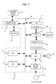
- FIG. 1 is a block diagram showing a control unit of a home-use game system to which the present invention is applied.
- the home-use game system executes predetermined games according to the game programs recorded on a CD-ROM 15 serving as a storage medium.
- the game system includes a CPU 1 mainly constituted by a microprocessor, a ROM 2 and a RAM 3 serving as main storage devices for the CPU 1, a graphics processing unit (GPU) for image processing, a frame buffer 5a and a Z-buffer 5b used by the GPU 4, and a CD-ROM reading device 8.
- GPU graphics processing unit
- the ROM 2 stores an operation system which is a program necessary for the operational control of the whole game system.
- the RAM 3 stores game program and image data read out, as needed, from the CD-ROM 15 serving as a storage medium.
- the image data includes polygon data for a plurality of polygons forming three-dimensional objects arranged in an imaginary three-dimensional space, and texture data to be put or pasted on the polygons to form two-dimensional images.
- Each polygon data includes information of vertex coordinates (x p , y p , z p ), texture coordinates (u p , v p ) of each vertex, and luminance information.
- the polygon vertex coordinate z (hereinafter referred to as "Z-value") represents depth of the vertex from the viewpoint of the game-player, and displaying the polygon with small Z-value is effective for opaque polygons.
- polygon is a polygonal two-dimensional imaginary graphic element forming objects set in the game space such as models and characters.
- the GPU 4 receives the polygon data from the CPU 1 and transforms the polygon of local coordinate system (x p , y p , z p ) to the data of world coordinate system.
- the GPU 4 transforms the polygon data of world coordinate system to the data of viewpoint coordinate system (x s , y s , z s ) (hereinafter referred to as "screen coordinate system (x s , y s , z s )”) by applying perspective projection transformation onto the positional coordinate data of the polygons in the world coordinate system.
- the GPU 4 thus draws the polygons on the frame buffer 5a and the Z-buffer 5b, transforms the drawn image data to a video signal and outputs it to the monitor 9 at appropriate timings.
- the Z-value is written onto the Z-buffer 5b.
- the "local coordinate system” is a coordinate system peculiar to each polygon, and moves if the polygon moves.
- the "world coordinate system” is fixed even if the polygon moves.
- the "screen coordinate system” represents the position on the screen where the polygon is eventually displayed.
- the texture put or pasted on the polygon by the texture mapping is determined based on the texture coordinate (u p , v p ) of each vertex.
- the texture has RGB channels (three primitive colors), and the design of the texture and optical density of the color are determined by the setting of the RGB channels.
- the texture also has A-(alpha) channel, by which the texture can be set to be transparent and the permissibility of drawing other (i.e., second) texture over the (first) texture can be set (such setting can be made by the texture area unit). For example, if the A-(alpha) channel is set such that the drawing of other texture is permitted, the design or pattern of second texture is displayed in the area where the second texture overlaps the first texture.
- the A-(alpha) channel is set such that the drawing is not permitted (i.e., inhibited)
- drawing the second texture is inhibited in the area where the second texture overlaps the first texture, and the design or pattern of the first texture is displayed.
- an intermediate levels between the drawing permitted level and the drawing inhibited level may be set.
- gradation may be set.
- the alpha value of a certain pixel is set to A1 and RGB values of the pixel are set to R1, R2 and R3, respectively, and that RGB values of another pixel are set to R2, G2 and B2, respectively
- the game system shown in FIG. 1 further includes a sound processing unit (SPU) 6 and a sound buffer 7.
- the SPU 6 reproduces voice and/or sound data and music source data read out from the CD-ROM 15 and stored in the sound buffer 7, and outputs the sound from the speaker 10.
- the CD-ROM reading device 8 reads out program and/or data recorded on the CD-ROM 15 in accordance with the instruction from the CPU 1, and outputs a signal corresponding to the contents thus read out. On the CD-ROM 15, program and data necessary for the execution of the game are recorded.
- a home-use television receiver may be used as the monitor 9.
- the communication control device 11 is connected to the CPU 1 via the bus 14, and the controller 12 and the auxiliary storage device 13 are detachably connected to the communication control device 11.
- the controller 12 functions as an input device, on which manipulation members to be manipulated by the game-player are provided.
- the communication control device 11 repeatedly scans the manipulation state of the controller 12 with a predetermined interval, and outputs the signal corresponding to the scanning result to the CPU 1.
- the CPU 1 judges the manipulation state of the controller 12 based on the signal from the controller 12.
- the components other than the monitor 9, the speaker 10, the controller 12, the CD-ROM 15 and the auxiliary storage device 13 are integrally accommodated in a single housing which constitutes the body unit 16 of the game system.
- the game program recorded on the CD-ROM 15 is loaded to the RAM 3 and executed by the CPU 1, and thus the game-player may play game of various genre on the screen of the monitor 9.
- the game is an action game, and program necessary for executing the action game by the game system as well as image data corresponding to the various scenes appearing in the action game are recorded on the CD-ROM 15.
- the character controlled by the game-player moves here and there in the imaginary three-dimensional space drawn on the monitor 9 and manipulates weapons such as guns to fight against enemy characters.
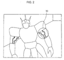
- FIG. 2 shows an example of image of a character displayed on the monitor 9.
- the character shown in FIG. 2 is a three-dimensional object formed by a plurality of polygons.
- FIG. 3 shows the magnified view of the arm portion 30 of the character shown in FIG. 2.
- the light movement lines 41 are formed on the surface of the arm portion 30, and the lighting portion 40 moves on the light movement lines 41 in the direction of the arrows. This is realized by varying the texture coordinate put (drawn) on the polygons of the arm portion 30 in order.
- the CPU 1 reads out the polygon data stored in the RAM 4, and transforms the local coordinates (x p , y p , z p ) of the vertexes of the polygons to the world coordinates and then to the screen coordinates (x s , y s , z s ) in step S1. Then, based on the texture coordinates (u p , v p ) that the polygons have, the RGB channels and the A-(alpha) channel of the first texture are written on the frame buffer 5a (step S2).
- the polygons with the first textures are displayed on the screen.
- the calculation amount may be reduced.
- the drawing permitted area for other texture and gradation area are set in the A-channel, and these data are written onto the A-channel area of the frame buffer 5a and the Z-buffer 5b.
- the object formed by a plurality of polygons is displayed on the screen of the monitor 9.
- FIG. 5 shows the object 50 of the arm portion 30 shown on the screen of the monitor 9.
- the object 50 of the arm portion is formed by the polygons 51, 52 and 53. Out of them, the portions 51a of the polygon 51 are gradation areas where gradation with other texture is made.
- the portion denoted by the reference number 51b is a drawing permitted area for other texture, and corresponds to the light movement line 41 in FIG. 2.
- the local coordinates (x p , y p , z p ) of the vertexes of the polygons drawn in step S1 are projected onto a predefined imaginary plane (e.g., an imaginary parallelogram plane) 55 as shown in FIG. 6 to calculate the second texture coordinate (u, v) (step S3).
- the texture coordinate (u, v) obtained by such projection may be calculated by the following predetermined equation, for example:
- P x , P y and P z are reference position vectors determining the position on which the second texture is to be put or pasted.
- the u bx , u by and u bz are u-direction reference vectors with respect to the reference position vector
- the v bx , v by and v bz are v-direction reference vectors with respect to the reference position vector.
- step S4 dynamically changing value (u', v') is added to the texture coordinates (u, v) obtained in step S3 to calculate the final second texture coordinates (u1, v1) (step S4).
- the second texture is read out from the RAM 4 and is drawn on the first texture of the polygon 51 with alpha-blending based on the final second texture coordinate (u1, v1) and the screen coordinate (x s , y s , z s ) of the polygon 51 transformed in step S1 (step S5).
- the screen coordinates (x s , y s , z s ) of the polygon 51 transformed in step S1 may be used in drawing the second texture thereby to reduce the calculation amount.
- FIG. 7 shows an example of the texture 60 read out at this time.
- the second texture 60 has their own coordinates and corresponds to the coordinate position of the imaginary plane 55.
- the optical density of the color increases.
- the colors of the area 60a and 60b are set to be black.
- the coordinate position of the second texture 60 drawn on the first texture of the polygon 51 is determined, by the texture coordinate (u1, v1) of the final second texture, as the four comers (A, B, C, D) of the area 60c shown in FIG. 7.
- FIG. 8 shows the state when the second texture 60 is put or pasted on the polygon 51.
- the texture put or pasted has an area larger than that of the polygon 51, but the area of the texture 60 overlapping the polygon 51 is actually displayed on the screen of the monitor 9.
- the gradation area 51 a is shown in such a manner that the light of the image of the second texture 60 is slightly mixed.
- the drawing permitted area 51b the image of the second texture 60 is displayed.
- the gradation area 51a may be set in such a manner that the aforementioned alpha value decreases as the distance from the drawing permitted area 51b increases. By this, as the distance from the drawing permitted area 51b increases, the image is shown in such a manner that the light of the image of the second texture 60 is gradually reduced.
- step S6 the value (u', v') of the coordinate of the second texture 60 is varied. Namely, for the subsequent drawing, the texture coordinate (u1, v1) is moved. Then, the process returns to step S1 for the next frame to execute the same processing, thereby the second texture is drawn based on the coordinate (u1, v1) of the second texture after the value (u', v') is varied. Then, by varying the value (u', v') in each frame, in order, the design or pattern of the second texture may be displayed as if it is moving.
- the texture 60 may be displayed as if it is moving on the polygon 51 in the u-direction as seen in FIG. 9. Further, since the color is getting denser as the value u in the u-direction increases as shown in FIG. 7, image can be displayed as if the lighting portion 40 is moving along the light movement line 41 (51b in FIG. 9) as shown in FIG. 3 and the light of the lighting portion 40 is moving in the gradation areas 51a with slightly leaking out.
- the lighting portion 40 can be moved on the polygons forming the character. While only the value u' is varied in the above description, both of the values u' and v' may be varied.
- the application of the invention is not limited to such case, and liquid, for example, may be moved. Further, by the appropriate combination of the color of the texture 60, the setting of the pattern and the setting of the mask area 51 on the polygon 51a, various expression may be achieved on the screen of the monitor 9.
- the present invention is applicable to the games of any genre, such as role-playing game, simulation game and action game.
- the texture put or pasted on the polygons displayed on the game screen may be moved by the coordinate transformation, and this enables specific representation or expression on the polygons. Further, by specifically setting the area on a part of the polygon where putting or pasting the texture is inhibited, more complicated representation or expression may be realized on the polygons.
Abstract
Description
- The present invention relates to a game system which projects and displays polygons having three-dimensional coordinates on a two-dimensional plane.
- Generally, in such a game system, models and characters, which are independent objects to be displayed on a screen, are formed by a plurality of polygons which are two-dimensional imaginary graphic elements of triangular or quadrangular shape. There is known a technique to visually represent specific images of models and characters by putting textures, which are two-dimensional image data, on the polygons. However, since the textures put on the polygons are still images, specific representation or expression is difficult to achieve.
- It is an object of the present invention to provide a game system capable of realizing specific visual representation or expression on polygons displayed on a screen of a game system.
- According to one aspect of the present invention, there is provided a game system for projectively transforming a plurality of polygons, which form three-dimensional object located in an imaginary three-dimensional space, to a viewpoint coordinate system to draw the polygons on a projection plane, including: a polygon drawing unit for drawing a polygon with a first texture which affects drawing of other texture; a second texture drawing unit for drawing a second texture, prepared in advance, on the polygon drawn by the polygon drawing unit based on two-dimensional coordinates of the second texture; and a texture moving unit for simulatively moving the second texture, drawn by the second texture drawing unit, on the polygon drawn by the polygon drawing unit by varying the two-dimensional coordinates in time-series.
- In accordance with the game system, the polygon with the first texture which affects drawing of other texture is drawn. Then, the second texture, prepared in advance, is drawn on the polygon based on the two-dimensional coordinates thereof. Then, by varying the two-dimensional coordinates of the second texture in time-series, the second texture thus drawn is simulatively moved on the polygon drawn. Therefore, it appears that the image of the second texture is moving, and specific representation may be achieved in association with the first texture.
- The two-dimensional coordinates of the second texture may be calculated by transforming three-dimensional coordinates of vertexes of the polygon. Thus, it is unnecessary that the coordinates of the second texture are stored as data for the vertexes of the polygon, and the coordinates of the second texture can be calculated by transforming the coordinates of the vertexes of the polygon. Therefore, data amount to be stored may be reduced.
- The two-dimensional coordinates of the second texture may be calculated by projectively transforming three-dimensional coordinates of vertexes of the polygon on an imaginary two-dimensional plane which is prepared in advance and corresponds to the two-dimensional coordinates. Thus, it is unnecessary that the coordinates of the second texture are stored as data for the vertexes of the polygon, and the coordinates of the second texture can be calculated by projectively transforming the coordinates of the vertexes of the polygon on the imaginary two-dimensional plane. Therefore, data amount to be stored may be reduced.
- The luminance of colors of the second texture may be different in different areas in the second texture. Thus, the luminance of the colors of the image are varied by moving the second texture, thereby enabling specific visual representation of the polygons with texture.
- The luminance of colors of the second texture may vary in proportion to coordinate value in either one direction of the two-dimensional coordinates if the two-dimensional coordinates are fixed. Therefore, by moving the second texture in either one direction of the two-dimensional coordinates, the image having bright color (e.g., lighting portion) and moving in a certain direction may be visually shown.
- A part of the second texture may undergo an affect of gradation by the first texture. Therefore, in the area where the gradation is applied, the light of the second texture is shown as moving with slightly leaking out.
- The gradation may be executed by mixing the colors of the first texture and the colors of the second texture with a predetermined mixing ratio. Therefore, various gradation may be achieved by controlling the mixing ratio.
- According to another aspect of the present invention, there is provided an image drawing method for projectively transforming a plurality of polygons, which form three-dimensional object located in an imaginary three-dimensional space, to a viewpoint coordinate system to draw the polygons on a projection plane, including the steps of: drawing a polygon with a first texture which affects drawing of other texture; drawing a second texture, prepared in advance, on the polygon drawn by the polygon drawing step based on two-dimensional coordinates of the second texture; and simulatively moving the second texture, drawn by the second texture drawing step, on the polygon drawn by the polygon drawing step by varying the two-dimensional coordinates in time-series.
- In accordance with this method, the image of the second texture can be shown as moving, and specific visual representation may be achieved in association with the first texture.
- According to still another aspect of the present invention, there is provided an image drawing method for projectively transforming a plurality of polygons, which form three-dimensional object located in an imaginary three-dimensional space, to a viewpoint coordinate system to draw the polygons on a projection plane, including the steps of: drawing a polygon with a first texture which affects drawing of other texture; projectively transforming three-dimensional coordinates of vertexes of the polygon on an imaginary two-dimensional plane, prepared in advance, to calculate two-dimensional coordinates of the second texture; drawing the second texture on the drawn polygon based on the calculated two-dimensional coordinates; and simulatively moving the second texture, drawn by the second texture drawing step, on the polygon drawn by the polygon drawing step by varying the two-dimensional coordinates in time-series.
- In accordance with this method, the image of the second texture can be shown as moving, and specific visual representation may be achieved in association with the first texture. In addition, it is unnecessary that the coordinates of the second texture are stored as data for the vertexes of the polygon, and the coordinates of the second texture can be calculated by projectively transforming the coordinates of the vertexes of the polygon on the imaginary two-dimensional plane. Therefore, data amount to be stored may be reduced.
- According to still another aspect of the present invention, there is provided a computer-readable storage medium carrying a game program for projectively transforming a plurality of polygons, which form three-dimensional object located in an imaginary three-dimensional space, to a viewpoint coordinate system to draw the polygons on a projection plane, the game program controls a computer to function as: a polygon drawing unit for drawing a polygon with a first texture which affects drawing of other texture; a second texture drawing unit for drawing a second texture, prepared in advance, on the polygon drawn by the polygon drawing unit based on two-dimensional coordinates of the second texture; and a texture moving unit for simulatively moving the second texture, drawn by the second texture drawing unit, on the polygon drawn by the polygon drawing unit by varying the two-dimensional coordinates in time-series.
- According to still another aspect of the present invention, there is provided a computer-readable storage medium carrying a game program for projectively transforming a plurality of polygons, which form three-dimensional object located in an imaginary three-dimensional space, to a viewpoint coordinate system to draw the polygons on a projection plane, the game program controls a computer to function as: a unit for drawing a polygon with a first texture which affects drawing of other texture; a unit for projectively transforming three-dimensional coordinates of vertexes of the polygon on an imaginary two-dimensional plane, prepared in advance, to calculate two-dimensional coordinates of the second texture; a unit for drawing the second texture on the drawn polygon based on the calculated two-dimensional coordinates; and a unit for simulatively moving the second texture, drawn by the second texture drawing unit, on the polygon drawn by the polygon drawing unit by varying the two-dimensional coordinates in time-series.
- By executing the program stored in those storage medium by a computer, the game system according to the present invention may be achieved.
- The nature, utility, and further features of this invention will be more clearly apparent from the following detailed description with respect to preferred embodiment of the invention when read in conjunction with the accompanying drawings briefly described below.
- In the Drawings;
- FIG. 1 is a block diagram showing a schematic configuration of a game system according to the present invention;
- FIG. 2 is a diagram showing an example of image of a character displayed on a screen;
- FIG. 3 is a magnified view of an arm portion of the character shown in FIG. 2, wherein lighting portions are moving;
- FIG. 4 is a flowchart showing image drawing process executed by the game system according to the present invention;
- FIG. 5 shows an object of the arm portion of the character shown on the screen;
- FIG. 6 is an explanatory view showing the manner that a polygon is projected onto a predefined imaginary plane;
- FIG. 7 shows an example of texture;
- FIG. 8 shows a manner the texture is put or pasted onto the polygon; and
- FIG. 9 shows the manner the texture put or pasted on the polygon moves.
-
- The preferred embodiment of the present invention will now be described below with reference to the attached drawings.
- FIG. 1 is a block diagram showing a control unit of a home-use game system to which the present invention is applied. The home-use game system executes predetermined games according to the game programs recorded on a CD-
ROM 15 serving as a storage medium. The game system includes aCPU 1 mainly constituted by a microprocessor, aROM 2 and a RAM 3 serving as main storage devices for theCPU 1, a graphics processing unit (GPU) for image processing, aframe buffer 5a and a Z-buffer 5b used by theGPU 4, and a CD-ROM reading device 8. - The
ROM 2 stores an operation system which is a program necessary for the operational control of the whole game system. The RAM 3 stores game program and image data read out, as needed, from the CD-ROM 15 serving as a storage medium. The image data includes polygon data for a plurality of polygons forming three-dimensional objects arranged in an imaginary three-dimensional space, and texture data to be put or pasted on the polygons to form two-dimensional images. Each polygon data includes information of vertex coordinates (xp, yp, zp), texture coordinates (up, vp) of each vertex, and luminance information. The polygon vertex coordinate z (hereinafter referred to as "Z-value") represents depth of the vertex from the viewpoint of the game-player, and displaying the polygon with small Z-value is effective for opaque polygons. It is noted that "polygon" is a polygonal two-dimensional imaginary graphic element forming objects set in the game space such as models and characters. TheGPU 4 receives the polygon data from theCPU 1 and transforms the polygon of local coordinate system (xp, yp, zp) to the data of world coordinate system. Then, theGPU 4 transforms the polygon data of world coordinate system to the data of viewpoint coordinate system (xs, ys, zs) (hereinafter referred to as "screen coordinate system (xs, ys, zs)") by applying perspective projection transformation onto the positional coordinate data of the polygons in the world coordinate system. TheGPU 4 thus draws the polygons on theframe buffer 5a and the Z-buffer 5b, transforms the drawn image data to a video signal and outputs it to themonitor 9 at appropriate timings. The Z-value is written onto the Z-buffer 5b. In drawing the polygons on theframe buffer 5a and the Z-buffer 5b, processing necessary for drawing, such as size variation corresponding to distance, texture mapping and lighting, are executed. The "local coordinate system" is a coordinate system peculiar to each polygon, and moves if the polygon moves. The "world coordinate system" is fixed even if the polygon moves. The "screen coordinate system" represents the position on the screen where the polygon is eventually displayed. - The texture put or pasted on the polygon by the texture mapping is determined based on the texture coordinate (up, vp) of each vertex. The texture has RGB channels (three primitive colors), and the design of the texture and optical density of the color are determined by the setting of the RGB channels. The texture also has A-(alpha) channel, by which the texture can be set to be transparent and the permissibility of drawing other (i.e., second) texture over the (first) texture can be set (such setting can be made by the texture area unit). For example, if the A-(alpha) channel is set such that the drawing of other texture is permitted, the design or pattern of second texture is displayed in the area where the second texture overlaps the first texture. Conversely, if the A-(alpha) channel is set such that the drawing is not permitted (i.e., inhibited), drawing the second texture is inhibited in the area where the second texture overlaps the first texture, and the design or pattern of the first texture is displayed. Further, in the A (alpha) channel, an intermediate levels between the drawing permitted level and the drawing inhibited level may be set. In other words, gradation may be set. By this, it is possible to express such a state that the light of second texture is slightly mixed into the first texture (not so completely like the drawing permitted area, but dimly visible). For example, assuming that the alpha value of a certain pixel is set to A1 and RGB values of the pixel are set to R1, R2 and R3, respectively, and that RGB values of another pixel are set to R2, G2 and B2, respectively, the colors (R,G,B) displayed on the screen are expressed as: R = R1 + A1 × R2, G = G1 + A1 × G2, B = B1 + A1 × B2. The alpha value A1 represents the mixing ratio of the first texture and the second texture, and the drawing the first texture is completely inhibited if A1=0. Namely, based on the value A1, the optical density of the second texture is determined. This is called "alpha blending" utilizing destination alpha.
- The game system shown in FIG. 1 further includes a sound processing unit (SPU) 6 and a
sound buffer 7. TheSPU 6 reproduces voice and/or sound data and music source data read out from the CD-ROM 15 and stored in thesound buffer 7, and outputs the sound from thespeaker 10. The CD-ROM reading device 8 reads out program and/or data recorded on the CD-ROM 15 in accordance with the instruction from theCPU 1, and outputs a signal corresponding to the contents thus read out. On the CD-ROM 15, program and data necessary for the execution of the game are recorded. A home-use television receiver may be used as themonitor 9. - Further, the
communication control device 11 is connected to theCPU 1 via thebus 14, and the controller 12 and theauxiliary storage device 13 are detachably connected to thecommunication control device 11. The controller 12 functions as an input device, on which manipulation members to be manipulated by the game-player are provided. Thecommunication control device 11 repeatedly scans the manipulation state of the controller 12 with a predetermined interval, and outputs the signal corresponding to the scanning result to theCPU 1. TheCPU 1 judges the manipulation state of the controller 12 based on the signal from the controller 12. In the above arrangement, the components other than themonitor 9, thespeaker 10, the controller 12, the CD-ROM 15 and theauxiliary storage device 13 are integrally accommodated in a single housing which constitutes thebody unit 16 of the game system. - In the above-described game system, the game program recorded on the CD-
ROM 15 is loaded to the RAM 3 and executed by theCPU 1, and thus the game-player may play game of various genre on the screen of themonitor 9. According to this embodiment, the game is an action game, and program necessary for executing the action game by the game system as well as image data corresponding to the various scenes appearing in the action game are recorded on the CD-ROM 15. In the action game of the embodiment, the character controlled by the game-player moves here and there in the imaginary three-dimensional space drawn on themonitor 9 and manipulates weapons such as guns to fight against enemy characters. - FIG. 2 shows an example of image of a character displayed on the
monitor 9. The character shown in FIG. 2 is a three-dimensional object formed by a plurality of polygons. FIG. 3 shows the magnified view of thearm portion 30 of the character shown in FIG. 2. As shown in FIG. 3, the light movement lines 41 are formed on the surface of thearm portion 30, and thelighting portion 40 moves on the light movement lines 41 in the direction of the arrows. This is realized by varying the texture coordinate put (drawn) on the polygons of thearm portion 30 in order. - The operation of the game system for displaying such image will be described with reference to the flowchart of FIG. 4 and explanatory diagrams of FIGS. 5 to 9. According to the progress of the game program, the
CPU 1 reads out the polygon data stored in theRAM 4, and transforms the local coordinates (xp, yp, zp) of the vertexes of the polygons to the world coordinates and then to the screen coordinates (xs, ys, zs) in step S1. Then, based on the texture coordinates (up, vp) that the polygons have, the RGB channels and the A-(alpha) channel of the first texture are written on theframe buffer 5a (step S2). By this, the polygons with the first textures are displayed on the screen. By simultaneously writing the RGB channels and the A-(alpha) channel on theframe buffer 5a, the calculation amount may be reduced. For the first texture, the drawing permitted area for other texture and gradation area are set in the A-channel, and these data are written onto the A-channel area of theframe buffer 5a and the Z-buffer 5b. Thus, the object formed by a plurality of polygons is displayed on the screen of themonitor 9. - FIG. 5 shows the
object 50 of thearm portion 30 shown on the screen of themonitor 9. Theobject 50 of the arm portion is formed by thepolygons portions 51a of thepolygon 51 are gradation areas where gradation with other texture is made. The portion denoted by thereference number 51b is a drawing permitted area for other texture, and corresponds to thelight movement line 41 in FIG. 2. - Subsequently, the local coordinates (xp, yp, zp) of the vertexes of the polygons drawn in step S1 are projected onto a predefined imaginary plane (e.g., an imaginary parallelogram plane) 55 as shown in FIG. 6 to calculate the second texture coordinate (u, v) (step S3). The texture coordinate (u, v) obtained by such projection may be calculated by the following predetermined equation, for example:Here, Px, Py and Pz are reference position vectors determining the position on which the second texture is to be put or pasted. The ubx, uby and ubz are u-direction reference vectors with respect to the reference position vector, and the vbx, vby and vbz are v-direction reference vectors with respect to the reference position vector. Thus, it is unnecessary to store texture coordinates of the second texture as the data for each vertexes of polygons, but they can be generated by projecting the polygon coordinates according to the above equation. This enables reduction of data amount to be stored. In addition, since the

imaginary plane 55 can be used in common for a plurality of polygons, the data amount may be reduced in comparison with the case where each polygon has an imaginary plane. Further, the second texture may be properly drawn even if the texture covers plural polygons. - Next, dynamically changing value (u', v') is added to the texture coordinates (u, v) obtained in step S3 to calculate the final second texture coordinates (u1, v1) (step S4). Namely, the calculation: (u1, v1) = (u, v) + (u', v') is executed. Here, the value (u', v') is being set as (u', v') = (0, 0), for example, at the initial setting stage.
- Next, the second texture is read out from the
RAM 4 and is drawn on the first texture of thepolygon 51 with alpha-blending based on the final second texture coordinate (u1, v1) and the screen coordinate (xs, ys, zs) of thepolygon 51 transformed in step S1 (step S5). Thus, the screen coordinates (xs, ys, zs) of thepolygon 51 transformed in step S1 may be used in drawing the second texture thereby to reduce the calculation amount. - FIG. 7 shows an example of the
texture 60 read out at this time. As seen in FIG. 7, thesecond texture 60 has their own coordinates and corresponds to the coordinate position of theimaginary plane 55. In the example of FIG. 7, as the value u in the u-direction increases, the optical density of the color increases. The colors of thearea second texture 60 drawn on the first texture of thepolygon 51 is determined, by the texture coordinate (u1, v1) of the final second texture, as the four comers (A, B, C, D) of thearea 60c shown in FIG. 7. - FIG. 8 shows the state when the
second texture 60 is put or pasted on thepolygon 51. In the example of FIG. 8, the texture put or pasted has an area larger than that of thepolygon 51, but the area of thetexture 60 overlapping thepolygon 51 is actually displayed on the screen of themonitor 9. As shown in FIG. 8, thegradation area 51 a is shown in such a manner that the light of the image of thesecond texture 60 is slightly mixed. In the drawing permittedarea 51b, the image of thesecond texture 60 is displayed. Thegradation area 51a may be set in such a manner that the aforementioned alpha value decreases as the distance from the drawing permittedarea 51b increases. By this, as the distance from the drawing permittedarea 51b increases, the image is shown in such a manner that the light of the image of thesecond texture 60 is gradually reduced. - Next, the value (u', v') of the coordinate of the
second texture 60 is varied (step S6). Namely, for the subsequent drawing, the texture coordinate (u1, v1) is moved. Then, the process returns to step S1 for the next frame to execute the same processing, thereby the second texture is drawn based on the coordinate (u1, v1) of the second texture after the value (u', v') is varied. Then, by varying the value (u', v') in each frame, in order, the design or pattern of the second texture may be displayed as if it is moving. For example, by varying the value u' from 0 to 10 stepwise in each frame, thetexture 60 may be displayed as if it is moving on thepolygon 51 in the u-direction as seen in FIG. 9. Further, since the color is getting denser as the value u in the u-direction increases as shown in FIG. 7, image can be displayed as if thelighting portion 40 is moving along the light movement line 41 (51b in FIG. 9) as shown in FIG. 3 and the light of thelighting portion 40 is moving in thegradation areas 51a with slightly leaking out. - In this way, by controlling the value (u', v'), the
lighting portion 40 can be moved on the polygons forming the character. While only the value u' is varied in the above description, both of the values u' and v' may be varied. - While the above described embodiment is directed to the movement of the lighting portion on the surface of the character's
arm portion 30, the application of the invention is not limited to such case, and liquid, for example, may be moved. Further, by the appropriate combination of the color of thetexture 60, the setting of the pattern and the setting of themask area 51 on thepolygon 51a, various expression may be achieved on the screen of themonitor 9. The present invention is applicable to the games of any genre, such as role-playing game, simulation game and action game. - As described above, according to the present invention, the texture put or pasted on the polygons displayed on the game screen may be moved by the coordinate transformation, and this enables specific representation or expression on the polygons. Further, by specifically setting the area on a part of the polygon where putting or pasting the texture is inhibited, more complicated representation or expression may be realized on the polygons.
Claims (11)
- A game system (16) for projectively transforming a plurality of polygons (50), which form three-dimensional object located in an imaginary three-dimensional space, to a viewpoint coordinate system to draw the polygons on a projection plane, comprising:a polygon drawing means (1, 4) for drawing a polygon with a first texture (51) which affects drawing of other texture;a second texture drawing means (1, 4) for drawing a second texture (60), prepared in advance, on the polygon drawn by the polygon drawing means based on two-dimensional coordinates of the second texture; anda texture moving means (1, 4) for simulatively moving the second texture, drawn by the second texture drawing means, on the polygon drawn by the polygon drawing means by varying the two-dimensional coordinates in time-series.
- The game system (16) according to claim 1, wherein the two-dimensional coordinates of the second texture are calculated by transforming three-dimensional coordinates of vertexes of the polygon.
- The game system (16) according to claim 1, wherein the two-dimensional coordinates of the second texture are calculated by projectively transforming three-dimensional coordinates of vertexes of the polygon on an imaginary two-dimensional plane which is prepared in advance and corresponds to the two-dimensional coordinates.
- The game system (16) according to any one of claims 1 to 3, wherein luminance of colors of the second texture are different in different areas in the second texture.
- The game system (16) according to any one of claims 1 to 3, wherein luminance of colors of the second texture vary in proportion to coordinate value in either one direction of the two-dimensional coordinates if the two-dimensional coordinates are fixed.
- The game system (16) according to any one of claims 1 to 5, wherein a part of the second texture undergoes an affect of gradation by the first texture.
- The game system (16) according to claim 6, wherein the gradation is executed by mixing the colors of the first texture and the colors of the second texture with a predetermined mixing ratio (A1).
- An image drawing method for projectively transforming a plurality of polygons (50), which form three-dimensional object located in an imaginary three-dimensional space, to a viewpoint coordinate system to draw the polygons on a projection plane, comprising the steps of:drawing a polygon with a first texture (51) which affects drawing of other texture;drawing a second texture (60), prepared in advance, on the polygon drawn by the polygon drawing step based on two-dimensional coordinates of the second texture; andsimulatively moving the second texture, drawn by the second texture drawing step, on the polygon drawn by the polygon drawing step by varying the two-dimensional coordinates in time-series.
- An image drawing method for projectively transforming a plurality of polygons (50), which form three-dimensional object located in an imaginary three-dimensional space, to a viewpoint coordinate system to draw the polygons on a projection plane, comprising the steps of:drawing a polygon with a first texture (51) which affects drawing of other texture;projectively transforming three-dimensional coordinates of vertexes of the polygon on an imaginary two-dimensional plane, prepared in advance, to calculate two-dimensional coordinates of second texture (60);drawing the second texture on the drawn polygon based on the calculated two-dimensional coordinates; andsimulatively moving the second texture, drawn by the second texture drawing step on the polygon drawn by the polygon drawing step by varying the two-dimensional coordinates in time-series.
- A computer-readable storage medium (15) carrying a game program for projectively transforming a plurality of polygons (50), which form three-dimensional object located in an imaginary three-dimensional space, to a viewpoint coordinate system to draw the polygons on a projection plane, the game program controls a computer to function as:a polygon drawing means (1, 4) for drawing a polygon (50) with a first texture (51) which affects drawing of other texture;a second texture drawing means (1, 4) for drawing a second texture (60), prepared in advance, on the polygon drawn by the polygon drawing means based on two-dimensional coordinates of the second texture; anda texture moving means (1, 4) for simulatively moving the second texture, drawn by the second texture drawing means, on the polygon drawn by the polygon drawing means by varying the two-dimensional coordinates in time-series.
- A computer-readable storage medium (15) carrying a game program for projectively transforming a plurality of polygons (50), which form three-dimensional object located in an imaginary three-dimensional space, to a viewpoint coordinate system to draw the polygons on a projection plane, the game program controls a computer to function as:a means (1, 4) for drawing a polygon with a first texture (51) which affects drawing of other texture;a means (1, 4) for projectively transforming three-dimensional coordinates of vertexes of the polygon on an imaginary two-dimensional plane, prepared in advance, to calculate two-dimensional coordinates of second texture;a means (1, 4) for drawing the second texture on the drawn polygon based on the calculated two-dimensional coordinates; anda means (1, 4) for simulatively moving the second texture, drawn by the second texture drawing means, on the polygon drawn by the polygon drawing means by varying the two-dimensional coordinates in time-series.
Applications Claiming Priority (2)
| Application Number | Priority Date | Filing Date | Title |
|---|---|---|---|
| JP2000088603A JP3367934B2 (en) | 2000-03-24 | 2000-03-24 | Game system, image drawing method in game system, and computer-readable recording medium storing game program |
| JP2000088603 | 2000-03-24 |
Publications (3)
| Publication Number | Publication Date |
|---|---|
| EP1139292A2 true EP1139292A2 (en) | 2001-10-04 |
| EP1139292A3 EP1139292A3 (en) | 2003-01-29 |
| EP1139292B1 EP1139292B1 (en) | 2006-08-02 |
Family
ID=18604459
Family Applications (1)
| Application Number | Title | Priority Date | Filing Date |
|---|---|---|---|
| EP01302722A Expired - Lifetime EP1139292B1 (en) | 2000-03-24 | 2001-03-23 | Game system, image drawing method for game system, and computer-readable storage medium storing game program |
Country Status (4)
| Country | Link |
|---|---|
| US (1) | US7245298B2 (en) |
| EP (1) | EP1139292B1 (en) |
| JP (1) | JP3367934B2 (en) |
| DE (1) | DE60121845T2 (en) |
Cited By (1)
| Publication number | Priority date | Publication date | Assignee | Title |
|---|---|---|---|---|
| WO2004107270A1 (en) * | 2003-05-30 | 2004-12-09 | Konami Corporation | Image processor and image processing method |
Families Citing this family (6)
| Publication number | Priority date | Publication date | Assignee | Title |
|---|---|---|---|---|
| JP3527489B2 (en) * | 2001-08-03 | 2004-05-17 | 株式会社ソニー・コンピュータエンタテインメント | Drawing processing method and apparatus, recording medium storing drawing processing program, drawing processing program |
| JP2005521123A (en) * | 2001-10-22 | 2005-07-14 | ライカ ミクロジュステムス ヴェツラー ゲーエムベーハー | Method and apparatus for generating three-dimensional image detected by optical microscope |
| US20050149992A1 (en) * | 2003-12-30 | 2005-07-07 | Lippincott Louis A. | Media center based multiple player game mode |
| JP2010033367A (en) * | 2008-07-29 | 2010-02-12 | Canon Inc | Information processor and information processing method |
| CN105597321B (en) * | 2015-12-18 | 2020-07-10 | 武汉斗鱼网络科技有限公司 | Bullet screen display method and system in full-screen game state |
| US10657698B2 (en) * | 2017-06-22 | 2020-05-19 | Microsoft Technology Licensing, Llc | Texture value patch used in GPU-executed program sequence cross-compilation |
Citations (3)
| Publication number | Priority date | Publication date | Assignee | Title |
|---|---|---|---|---|
| WO1998022911A1 (en) * | 1996-11-21 | 1998-05-28 | Philips Electronics N.V. | Method and apparatus for generating a computer graphics image |
| JPH10198819A (en) * | 1997-01-10 | 1998-07-31 | Konami Co Ltd | Water surface image display device, its image displaying method, and machine-readable recording medium recording computer program |
| US5949426A (en) * | 1997-01-28 | 1999-09-07 | Integrated Device Technology, Inc. | Non-linear texture map blending |
Family Cites Families (7)
| Publication number | Priority date | Publication date | Assignee | Title |
|---|---|---|---|---|
| US5537224A (en) * | 1992-11-24 | 1996-07-16 | Sony Corporation | Texture mapping image processing method and apparatus |
| US5790950A (en) * | 1994-03-18 | 1998-08-04 | Fujitsu Limited | Computer graphics apparatus having an improved walk-through function |
| JP3723301B2 (en) * | 1996-11-21 | 2005-12-07 | 任天堂株式会社 | Image creation device, image display device, and game device |
| US6320580B1 (en) * | 1997-11-07 | 2001-11-20 | Sega Enterprises, Ltd. | Image processing apparatus |
| JP2000176176A (en) * | 1998-09-18 | 2000-06-27 | Sega Enterp Ltd | Game machine |
| JP3809294B2 (en) * | 1999-03-31 | 2006-08-16 | 株式会社スクウェア・エニックス | GAME DEVICE, GAME METHOD, COMPUTER-READABLE RECORDING MEDIUM |
| JP2001204964A (en) * | 2000-01-28 | 2001-07-31 | Square Co Ltd | Computer-readable recording medium wherein program of game for ball game is recorded, method of displaying and processing image of game for ball game, and video game apparatus |
-
2000
- 2000-03-24 JP JP2000088603A patent/JP3367934B2/en not_active Expired - Fee Related
-
2001
- 2001-03-23 US US09/816,204 patent/US7245298B2/en not_active Expired - Lifetime
- 2001-03-23 DE DE60121845T patent/DE60121845T2/en not_active Expired - Lifetime
- 2001-03-23 EP EP01302722A patent/EP1139292B1/en not_active Expired - Lifetime
Patent Citations (3)
| Publication number | Priority date | Publication date | Assignee | Title |
|---|---|---|---|---|
| WO1998022911A1 (en) * | 1996-11-21 | 1998-05-28 | Philips Electronics N.V. | Method and apparatus for generating a computer graphics image |
| JPH10198819A (en) * | 1997-01-10 | 1998-07-31 | Konami Co Ltd | Water surface image display device, its image displaying method, and machine-readable recording medium recording computer program |
| US5949426A (en) * | 1997-01-28 | 1999-09-07 | Integrated Device Technology, Inc. | Non-linear texture map blending |
Non-Patent Citations (1)
| Title |
|---|
| PATENT ABSTRACTS OF JAPAN vol. 1998, no. 12, 31 October 1998 (1998-10-31) & JP 10 198819 A (KONAMI CO LTD), 31 July 1998 (1998-07-31) * |
Cited By (2)
| Publication number | Priority date | Publication date | Assignee | Title |
|---|---|---|---|---|
| WO2004107270A1 (en) * | 2003-05-30 | 2004-12-09 | Konami Corporation | Image processor and image processing method |
| US7199801B2 (en) | 2003-05-30 | 2007-04-03 | Konami Corporation | Image processing apparatus and image processing method |
Also Published As
| Publication number | Publication date |
|---|---|
| US7245298B2 (en) | 2007-07-17 |
| EP1139292B1 (en) | 2006-08-02 |
| US20010024206A1 (en) | 2001-09-27 |
| DE60121845T2 (en) | 2006-12-07 |
| DE60121845D1 (en) | 2006-09-14 |
| JP2001273519A (en) | 2001-10-05 |
| EP1139292A3 (en) | 2003-01-29 |
| JP3367934B2 (en) | 2003-01-20 |
Similar Documents
| Publication | Publication Date | Title |
|---|---|---|
| US8602888B2 (en) | Video game device and image processing program | |
| US6738061B2 (en) | Method, apparatus, storage medium, program, and program product for generating image data of virtual three-dimensional space | |
| US20090244064A1 (en) | Program, information storage medium, and image generation system | |
| US7046242B2 (en) | Game system, program and image generating method | |
| EP1191482A2 (en) | Three-dimensional image processing method and apparatus | |
| EP1312047B1 (en) | Apparatus and method for rendering antialiased image | |
| JP2006195882A (en) | Program, information storage medium and image generation system | |
| EP0948979B1 (en) | Image creating apparatus, image creating method, and computer-readable recording medium containing image creating program | |
| EP1139292B1 (en) | Game system, image drawing method for game system, and computer-readable storage medium storing game program | |
| US6828969B2 (en) | Game system, program and image generating method | |
| EP0948978B1 (en) | Image creating apparatus, image creating method, and computer-readable recording medium containing image creating program | |
| JP3502796B2 (en) | 3D model display method and apparatus in video game, game apparatus, and computer-readable recording medium storing 3D model display program for video game | |
| JP2005032140A (en) | Image generation system, program, and information storage medium | |
| JP4749064B2 (en) | Program, information storage medium, and image generation system | |
| EP1362622B1 (en) | Video game apparatus and control method thereof | |
| JP4749198B2 (en) | Program, information storage medium, and image generation system | |
| JPH09245191A (en) | Transparency transformation method, its device and image processor | |
| JP2009129167A (en) | Program, information storage medium, and image generation system | |
| JP4073031B2 (en) | Program, information storage medium, and image generation system | |
| US6680734B2 (en) | Game system, imaging method in the game system, and computer readable storage medium having game program stored therein | |
| JP4528008B2 (en) | Program, information storage medium, and image generation system | |
| JP4521811B2 (en) | Program, information storage medium, and image generation system | |
| JPH11238145A (en) | Two-dimensional display method of three-dimensional stereoscopic structure | |
| JP2000132707A (en) | Game system and displaying method in game system | |
| JP2005157541A (en) | Program, information storage medium, and image generating system |
Legal Events
| Date | Code | Title | Description |
|---|---|---|---|
| PUAI | Public reference made under article 153(3) epc to a published international application that has entered the european phase |
Free format text: ORIGINAL CODE: 0009012 |
|
| AK | Designated contracting states |
Kind code of ref document: A2 Designated state(s): AT BE CH CY DE DK ES FI FR GB GR IE IT LI LU MC NL PT SE TR |
|
| AX | Request for extension of the european patent |
Free format text: AL;LT;LV;MK;RO;SI |
|
| PUAL | Search report despatched |
Free format text: ORIGINAL CODE: 0009013 |
|
| AK | Designated contracting states |
Designated state(s): AT BE CH CY DE DK ES FI FR GB GR IE IT LI LU MC NL PT SE TR |
|
| AX | Request for extension of the european patent |
Extension state: AL LT LV MK RO SI |
|
| 17P | Request for examination filed |
Effective date: 20030711 |
|
| AKX | Designation fees paid |
Designated state(s): DE FR GB |
|
| GRAP | Despatch of communication of intention to grant a patent |
Free format text: ORIGINAL CODE: EPIDOSNIGR1 |
|
| GRAS | Grant fee paid |
Free format text: ORIGINAL CODE: EPIDOSNIGR3 |
|
| GRAA | (expected) grant |
Free format text: ORIGINAL CODE: 0009210 |
|
| AK | Designated contracting states |
Kind code of ref document: B1 Designated state(s): DE FR GB |
|
| REG | Reference to a national code |
Ref country code: GB Ref legal event code: FG4D |
|
| REF | Corresponds to: |
Ref document number: 60121845 Country of ref document: DE Date of ref document: 20060914 Kind code of ref document: P |
|
| ET | Fr: translation filed | ||
| PLBE | No opposition filed within time limit |
Free format text: ORIGINAL CODE: 0009261 |
|
| STAA | Information on the status of an ep patent application or granted ep patent |
Free format text: STATUS: NO OPPOSITION FILED WITHIN TIME LIMIT |
|
| 26N | No opposition filed |
Effective date: 20070503 |
|
| REG | Reference to a national code |
Ref country code: GB Ref legal event code: 732E |
|
| REG | Reference to a national code |
Ref country code: FR Ref legal event code: TP |
|
| REG | Reference to a national code |
Ref country code: FR Ref legal event code: PLFP Year of fee payment: 15 |
|
| PGFP | Annual fee paid to national office [announced via postgrant information from national office to epo] |
Ref country code: DE Payment date: 20150320 Year of fee payment: 15 |
|
| PGFP | Annual fee paid to national office [announced via postgrant information from national office to epo] |
Ref country code: GB Payment date: 20150319 Year of fee payment: 15 Ref country code: FR Payment date: 20150319 Year of fee payment: 15 |
|
| REG | Reference to a national code |
Ref country code: DE Ref legal event code: R119 Ref document number: 60121845 Country of ref document: DE |
|
| GBPC | Gb: european patent ceased through non-payment of renewal fee |
Effective date: 20160323 |
|
| REG | Reference to a national code |
Ref country code: FR Ref legal event code: ST Effective date: 20161130 |
|
| PG25 | Lapsed in a contracting state [announced via postgrant information from national office to epo] |
Ref country code: DE Free format text: LAPSE BECAUSE OF NON-PAYMENT OF DUE FEES Effective date: 20161001 Ref country code: GB Free format text: LAPSE BECAUSE OF NON-PAYMENT OF DUE FEES Effective date: 20160323 Ref country code: FR Free format text: LAPSE BECAUSE OF NON-PAYMENT OF DUE FEES Effective date: 20160331 |