EP1139443A1 - Method and apparatus for driving a piezoelectric fuel injector element - Google Patents
Method and apparatus for driving a piezoelectric fuel injector element Download PDFInfo
- Publication number
- EP1139443A1 EP1139443A1 EP00106988A EP00106988A EP1139443A1 EP 1139443 A1 EP1139443 A1 EP 1139443A1 EP 00106988 A EP00106988 A EP 00106988A EP 00106988 A EP00106988 A EP 00106988A EP 1139443 A1 EP1139443 A1 EP 1139443A1
- Authority
- EP
- European Patent Office
- Prior art keywords
- bank
- triac
- piezoelectric element
- drive circuit
- driving
- Prior art date
- Legal status (The legal status is an assumption and is not a legal conclusion. Google has not performed a legal analysis and makes no representation as to the accuracy of the status listed.)
- Granted
Links
- 239000000446 fuel Substances 0.000 title claims abstract description 44
- 238000000034 method Methods 0.000 title claims abstract description 12
- 238000007599 discharging Methods 0.000 claims abstract description 11
- 238000002347 injection Methods 0.000 description 41
- 239000007924 injection Substances 0.000 description 41
- 230000004913 activation Effects 0.000 description 17
- 238000006073 displacement reaction Methods 0.000 description 5
- 238000002485 combustion reaction Methods 0.000 description 3
- 230000007547 defect Effects 0.000 description 3
- 230000008602 contraction Effects 0.000 description 2
- 230000002950 deficient Effects 0.000 description 2
- 238000010304 firing Methods 0.000 description 2
- 238000013459 approach Methods 0.000 description 1
- 239000003990 capacitor Substances 0.000 description 1
- 230000001419 dependent effect Effects 0.000 description 1
- 238000011161 development Methods 0.000 description 1
- 230000018109 developmental process Effects 0.000 description 1
- 238000010586 diagram Methods 0.000 description 1
- 230000000694 effects Effects 0.000 description 1
- 239000012530 fluid Substances 0.000 description 1
- 239000000203 mixture Substances 0.000 description 1
- 239000004065 semiconductor Substances 0.000 description 1
- 230000001960 triggered effect Effects 0.000 description 1
Images


Classifications
-
- F—MECHANICAL ENGINEERING; LIGHTING; HEATING; WEAPONS; BLASTING
- F02—COMBUSTION ENGINES; HOT-GAS OR COMBUSTION-PRODUCT ENGINE PLANTS
- F02D—CONTROLLING COMBUSTION ENGINES
- F02D41/00—Electrical control of supply of combustible mixture or its constituents
- F02D41/22—Safety or indicating devices for abnormal conditions
- F02D41/221—Safety or indicating devices for abnormal conditions relating to the failure of actuators or electrically driven elements
-
- F—MECHANICAL ENGINEERING; LIGHTING; HEATING; WEAPONS; BLASTING
- F02—COMBUSTION ENGINES; HOT-GAS OR COMBUSTION-PRODUCT ENGINE PLANTS
- F02D—CONTROLLING COMBUSTION ENGINES
- F02D41/00—Electrical control of supply of combustible mixture or its constituents
- F02D41/20—Output circuits, e.g. for controlling currents in command coils
- F02D41/2096—Output circuits, e.g. for controlling currents in command coils for controlling piezoelectric injectors
Definitions
- the present invention relates to an apparatus as defined in the preamble of claim 1, and a method as defined in the preamble of claim 7, i.e. a method and an apparatus for driving piezoelectric fuel injector elements divided into a plurality of injector banks, each bank containing at least one piezoelectric element used as an fuel injector actuator.
- piezoelectric elements being considered in more detail are, in particular but not exclusively, piezoelectric elements used as actuators. Piezoelectric elements can be used for such purposes because, as is known, they possess the property of contracting or expanding as a function of a voltage applied thereto or occurring therein.
- piezoelectric elements as actuators proves to be advantageous, inter alia, in fuel injection nozzles for internal combustion engines.
- Piezoelectric elements are capacitative elements which, as already partially alluded to above, contract and expand in accordance with the particular charge state or the voltage occurring therein or applied thereto.
- expansion and contraction of piezoelectric elements is used to control valves that manipulate the linear strokes of injection needles.
- the multiple-acting valves are used to execute the opening and the closing of the fuel injection nozzles.
- a piezoelectric element may be used to actuate the multiple-acting valve.
- Fig. 6 is a schematic representation of a fuel injection system using a piezoelectric element 2010 as an actuator.
- the piezoelectric element 2010 is electrically energized to expand and contract in response to a given activation voltage.
- the piezoelectric element 2010 is coupled to a piston 2015.
- the piezoelectric element 2010 causes the piston 2015 to protrude into a hydraulic adapter 2020 which contains a hydraulic fluid, for example fuel.
- a double acting control valve 2025 is hydraulically pushed away from hydraulic adapter 2020 and the valve plug 2035 is extended away from a first closed position 2040.
- double acting control valve 2025 and hollow bore 2050 is often referred to as double acting, double seat valve for the reason that when piezoelectric element 2010 is in an unexcited state, the double acting control valve 2025 rests in its first closed position 2040. On the other hand, when the piezoelectric element 2010 is fully extended, it rests in its second closed position 2030.
- the later position of valve plug 2035 is schematically represented with ghost lines in Fig. 6.
- the fuel injection system comprises an injection needle 2070 allowing for injection of fuel from a pressurized fuel supply line 2060 into the cylinder (not shown).
- the double acting control valve 2025 rests respectively in its first closed position 2040 or in its second closed position 2030. In either case, the hydraulic rail pressure maintains injection needle 2070 at a closed position. Thus, the fuel mixture does not enter into the cylinder (not shown).
- the piezoelectric element 2010 is excited such that double acting control valve 2025 is in the so-called mid-position with respect to the hollow bore 2050, then there is a pressure drop in the pressurized fuel supply line 2060. This pressure drop results in a pressure differential in the pressurized fuel supply line 2060 between the top and the bottom of the injection needle 2070 so that the injection needle 2070 is lifted allowing for fuel injection into the cylinder (not shown).
- a fuel injection nozzle implemented as a double acting, double seat valve to control linear stroke of a needle for fuel injection into a cylinder of an internal combustion engine
- the amount of fuel injected into a corresponding cylinder is a function of the time the valve is open, and in the case of the use of a piezoelectric element, an activation voltage applied to the piezoelectric element.
- the piezoelectric element is to be expanded or contracted by the effect of an activation voltage so that a controlled valve plug is positioned midway between the two seats of the double seat valve to position the corresponding injection needle for maximum fuel flow during a set time period.
- the actuators are divided into two banks each having one or more piezoelectric elements in parallel, with bank select switches for selecting the bank that is to be charged or discharged.
- the bank select switches were implemented as semiconductor switches (e.g. IGBT or MOSFET switches) that either conducted or blocked current in one direction, depending on the drive signal.
- a back-to-back diode connection operated in the other current direction.
- overlapping injections i.e., overlapping voltage shapes
- the present invention provides for:
- Embodiments of the present invention make it possible to shut down a defective piezoelectric actuator, or bank of actuators, by using a special type of switch in place of the previous select switches. In the event of an error or defect, operation of the other banks is possible independently, and emergency operation of the fuel injection system and of the engine is also possible, thereby preventing a total failure of the vehicle.
- bank cylinder switches are not employed and an additional main switch is included in the circuitry. This makes is possible to realize overlapping voltage shapes for any cylinders.
- one bank selector switch is provided for each cylinder. This permits the realization of overlapping voltage shapes and therefore overlapping injections on any two or more cylinders.
- the present invention in some embodiments requires fewer electrical components for implementation, thereby saving cost and space.
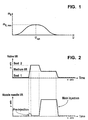
- Fig. 1 shows a graph depicting the relationship between activation voltage U and injected fuel volume m E during a preselected fixed time period, for an exemplary fuel injection system using piezoelectric elements acting upon double seat control valves.
- the y-axis represents volume of fuel injected into a cylinder chamber during the preselected fixed period of time.
- the x-axis represents the activation voltage applied to or stored in the corresponding piezoelectric element, used to displace a valve plug of the double seat control valve.
- the activation voltage U is zero, and the valve plug' is seated in a first closed version to prevent the flow of fuel during the preselected fixed period of time.
- the represented values of the activation voltage U cause the displacement of the valve plug away from the first seat and towards the second seat, in a manner that results in a greater volume of injected fuel for the fixed time period, as the activation voltage approaches U opt , up to the value for volume indicted on the y-axis by m E,max .
- the point m E,max corresponding to the greatest volume for the injected fuel during the fixed period of time, represents the value of the activation voltage for application to or charging of the piezoelectric element, that results in an optimal displacement of the valve plug between the first and second valve seats.
- the volume of fuel injected during the fixed period of time decrease until it reaches zero. This represents displacement of the valve plug from the optimal point and toward the second seat of the double acting control valve until the valve plug is seated in its second closed position.
- the graph of Fig. 1 illustrates that a maximum volume of fuel injection occurs when the activation voltage causes the piezoelectric element to displace the valve plug to the optimal point.
- the present invention teaches that the value for U opt at any given time for a particular piezoelectric element is influenced by the operating characteristics of the particular piezoelectric element at that time. That is, the amount of displacement caused by the piezoelectric element for a certain activation voltage varies as a function of the operating characteristics of the particular piezoelectric element. Accordingly, in order to achieve a maximum volume of fuel injection, m E,max , during a given fixed period of time, the activation voltage applied to or occurring in the piezoelectric element should be set to a value relevant to current operating characteristics of the particular piezoelectric element, to achieve U opt .
- Fig. 2 shows a double graph representing a schematic profile of an exemplary control valve stroke, to illustrate the double seat valve operation discussed above.
- the x-axis represents time
- the y-axis represents displacement of the valve plug (valve lift).
- the x-axis once again represents time
- the y-axis represents a nozzle needle lift to provide fuel flow, resulting from the valve lift of the upper graph.
- the upper and lower graphs are aligned with one another to coincide in time, as represented by the respective x-axises.
- the piezoelectric element is charged resulting in an expansion of the piezoelectric element, as will be described in greater detail, and causing the corresponding valve plug to move from the first seat to the second seat for a pre-injection stroke, as shown in the upper graph of Fig. 2.
- the lower graph of Fig. 2 shows a small injection of fuel that occurs as the valve plug moves between the two seats of the double seat valve, opening and closing the valve as the plug moves between the seats.
- the charging of the piezoelectric element can be done in two steps: the first one is to charge it to a certain voltage and cause the valve to open and the second one is to charge it further and cause the valve to close again at the second seat. Between these steps, in general, there can be a certain time delay.
- a discharging operation is then performed, as will be explained in greater detail below, to reduce the charge within the piezoelectric element so that it contracts, as will also be described in greater detail, causing the valve plug to move away from the second seat, and hold at a midway point between the two seats.
- the activation voltage within the piezoelectric element is to reach a value that equals U opt to correspond to an optimal point of the valve lift, and thereby obtain a maximum fuel flow, m E,max , during the period of time allocated to a main injection.
- the upper and lower graphs of Fig. 2 show the holding of the valve lift at a midway point, resulting in a main fuel injection.
- the piezoelectric element is discharged to an activation voltage of zero, resulting in further contraction of the piezoelectric element, to cause the valve plug to move away from the optimal position, towards the first seat, closing the valve and stopping fuel flow, as shown in the upper and lower graphs of Fig. 2.
- the valve plug will once again be in a position to repeat another pre-injection, main injection cycle, as just described above, for example.
- any other injection cycle can be performed.
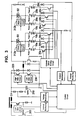
- each bank select switch S1 and S2 drive banks of piezoelectric elements 10, 20, wherein each bank contains more than one element 10a-10c, 20a-20c, and wherein each bank select switch is designed as a triac is shown.
- Triac driving circuits 312a, 312b are provided for driving switches S1 and S2, respectively.
- each piezoelectric element actuates an injection valve of a corresponding respective cylinder of an internal combustion engine.
- Cylinder select switches 30, 40 are provided for selectively controlling a given respective piezoelectric element 10, 20.
- battery 200 and capacitor 210 are used to charge and discharge piezoelectric elements 10, 20 via charging switch 220 and discharging switch 230, respectively.
- a bank select switch S1-S6 is provided for each respective cylinder.
- bank select switches S1-S6 are implemented as triacs, with triac driving circuit 312 being provided for driving the triacs.
- No cylinder select switches 30, 40 (Fig. 3) are required.
- each cylinder has its own piezoelectric element bank 10a-10c, 20a-20c, permitting maximum flexibility in control of the piezoelectric elements.
- main switch 39 is provided lowside.
- Main switch 39 may be an IGBT or a MOSFET.
- S1-S6 triac
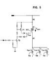
- Fig. 5 the drive circuit of the triac switch S1 is shown. This circuit must be provided once for each bank of piezoelectric elements 10. Voltages of either polarity can be applied to switch S1 (U A2A1 ). When not triggered, the triac S1 blocks the connected bank, i.e., piezoelectric elements 10a-10c in Fig. 3, and the connected bank cannot be operated. The triac does not conduct until a specific firing current is flowing at gate 313. When used as a bank select switch, reliable drive for the triac is necessary. The reasons for this are two-fold. First, reliable drive is necessary to prevent an unintended firing, regardless of the polarity of the main line (A1, A2). Second, reliable drive makes possible reliable switch-on during both the charging process (current flowing from A2 to A1) and during the discharging process (current flowing from A1 to A2).
- the drive circuit of the triac is specially adapted for use in the piezoelectric output stage, and is very simply designed with two transistors T1, T2, as is shown in Fig. 5.
- a positive voltage U A2A1 is set.
- transistor T2 (which, in one embodiment, is an npn transistor) conducts.
- transistor T1 (which, in one embodiment, is a pnp transistor) to conduct a positive gate current I Gate by way of its emitter-collector junction. This gate current fires the triac, and the corresponding piezoelectric element or bank of elements is charged.
- a negative voltage U A2A1 appears first. Again, driving the triac drive circuit causes transistor T2 to conduct.
- a negative gate current I Gate flows by way of its emitter-base junction. This gate current causes the triac to fire in the reverse direction and the corresponding piezoelectric element or bank of elements is discharged.
- transistor T1 has no function.
Abstract
Description
- it is possible to drive at least the other bank, or banks for systems with more than two banks, even in the presence of an error on one bank; and
- overlapping voltage shapes of injectors for any two or more injectors is made possible by providing a separate bank for each cylinder of the engine.
- designing the bank select switches S1 and S2 (or any bank select switches) as triacs; and
- shutting down the injector bank when the triac drive circuit is not driven; or
- providing one bank select switch for each cylinder as a triac and providing a main switch as an IGBT or a MOSFET, in which case cylinder select switches are not employed.
- Fig. 1
- shows a graph depicting the relationship between activation voltage and injected fuel volume in a fixed time period for a double acting control valve;
- Fig. 2
- shows a schematic profile of an exemplary control valve stroke;
- Fig. 3
- shows a schematic diagram of an exemplary piezoelectric element control system according to the present invention;
- Fig. 4
- shows another embodiment of a piezoelectric element control system according to the present invention;
- Fig. 5
- shows a schematic profile of a triac switch, including its drive circuit, for a bank of piezoelectric elements; and
- Fig. 6
- shows a schematic representation of an exemplary fuel injection system using a piezoelectric element as an actuator.
Claims (10)
- An apparatus for driving piezoelectric fuel injector elements divided into a plurality of injector banks, each bank containing at least one piezoelectric element (10, 20), each bank being selected for charging or discharging by a bank-selection switch (S1, S2, S3, S4, S5, S6), characterized in that a bank selection switch includes a triac with a triac drive circuit (312).
- The apparatus as defined in claim 1, characterized in that an injector bank is shut down when the triac drive circuit (312) is not driven.
- The apparatus as defined in claim 2 or 3, characterized in that the triac is driven by two transistors.
- The apparatus as defined in claim 3, characterized in that one transistor is an npn transistor, and the other transistor is a pnp transistor.
- The apparatus as defined in claim 1, characterized in that a main switch (39) low side is provided for stopping a charging or discharging current when an error occurs.
- The apparatus as defined in claim 5, characterized in that the main switch (39) is at least one of a MOSFET and an IGBT with reverse diode.
- A method for driving piezoelectric fuel injector elements divided into a plurality of injector banks, each bank containing at least one piezoelectric element, each bank being selected for charging or discharging by a bank selection-switch, characterized by driving a triac drive circuit.
- The method as defined in claim 7, characterized by shutting down an injector bank when the triac drive circuit is not driven.
- The method as defined in claim 7 or 8, characterized in that driving a triac drive circuit includes charging and discharging the circuit.
- The method as defined in claim 9, characterized in that charging the triac drive circuit includes setting a positive voltage across the triac drive circuit.
Priority Applications (4)
| Application Number | Priority Date | Filing Date | Title |
|---|---|---|---|
| EP00106988A EP1139443B1 (en) | 2000-04-01 | 2000-04-01 | Method and apparatus for driving a piezoelectric fuel injector element |
| DE60043000T DE60043000D1 (en) | 2000-04-01 | 2000-04-01 | Method and device for controlling a piezoelectric fuel injection valve |
| JP2001103951A JP2002021619A (en) | 2000-04-01 | 2001-04-02 | Driving device for piezoelectric fuel injection element and driving method thereof |
| US09/824,191 US20030205949A1 (en) | 2000-04-01 | 2001-04-02 | Method and apparatus for driving a plural bank piezoelectric fuel injector element with bank-selection switches and triac drive circuit |
Applications Claiming Priority (1)
| Application Number | Priority Date | Filing Date | Title |
|---|---|---|---|
| EP00106988A EP1139443B1 (en) | 2000-04-01 | 2000-04-01 | Method and apparatus for driving a piezoelectric fuel injector element |
Publications (2)
| Publication Number | Publication Date |
|---|---|
| EP1139443A1 true EP1139443A1 (en) | 2001-10-04 |
| EP1139443B1 EP1139443B1 (en) | 2009-09-23 |
Family
ID=8168328
Family Applications (1)
| Application Number | Title | Priority Date | Filing Date |
|---|---|---|---|
| EP00106988A Expired - Lifetime EP1139443B1 (en) | 2000-04-01 | 2000-04-01 | Method and apparatus for driving a piezoelectric fuel injector element |
Country Status (4)
| Country | Link |
|---|---|
| US (1) | US20030205949A1 (en) |
| EP (1) | EP1139443B1 (en) |
| JP (1) | JP2002021619A (en) |
| DE (1) | DE60043000D1 (en) |
Cited By (4)
| Publication number | Priority date | Publication date | Assignee | Title |
|---|---|---|---|---|
| FR2847001A1 (en) * | 2002-11-13 | 2004-05-14 | Renault Sa | Control of fuel injectors for motor vehicle engines, uses monitoring of electric signals in the excitation circuit to detect failures of piezoelectric cells in the injectors |
| WO2007009862A1 (en) * | 2005-07-19 | 2007-01-25 | Vdo Automotive Ag | Device for charging and discharging at least one piezoactuator for an injection valve of an internal combustion engine |
| DE102013216552A1 (en) * | 2013-08-21 | 2015-02-26 | Continental Automotive Gmbh | Device for operating at least one designed as a laser diode light-emitting diode |
| US10907567B2 (en) | 2018-01-03 | 2021-02-02 | Ford Global Technologies, Llc | System and method for operating a fuel injector |
Families Citing this family (11)
| Publication number | Priority date | Publication date | Assignee | Title |
|---|---|---|---|---|
| JP4604356B2 (en) * | 2001-01-23 | 2011-01-05 | 株式会社デンソー | Piezo actuator driving circuit and fuel injection device |
| US6912998B1 (en) * | 2004-03-10 | 2005-07-05 | Cummins Inc. | Piezoelectric fuel injection system with rate shape control and method of controlling same |
| ES2286926B1 (en) * | 2005-09-07 | 2008-12-01 | Kafloat, S.L. | FLOATING DEVICE, ASSEMBLY PROCEDURE AND OPERATION OF THE SAME. |
| JP4434248B2 (en) * | 2007-08-22 | 2010-03-17 | 株式会社デンソー | Piezo actuator drive unit |
| JP5007204B2 (en) * | 2007-11-12 | 2012-08-22 | ボッシュ株式会社 | Injector driver circuit |
| JP5083159B2 (en) * | 2008-10-03 | 2012-11-28 | 株式会社デンソー | Injector drive device |
| DE102014212377B4 (en) * | 2014-06-27 | 2016-07-21 | Continental Automotive Gmbh | Method for determining a state of an injection valve |
| JP2020088020A (en) * | 2018-11-16 | 2020-06-04 | ソニーセミコンダクタソリューションズ株式会社 | Detection circuit, drive circuit, and light-emitting device |
| JP7414729B2 (en) * | 2018-11-27 | 2024-01-16 | ソニーセミコンダクタソリューションズ株式会社 | Drive device and light emitting device |
| US11728621B2 (en) * | 2019-06-05 | 2023-08-15 | Stmicroelectronics (Research & Development) Limited | Voltage controlled steered VCSEL driver |
| US11579290B2 (en) | 2019-06-05 | 2023-02-14 | Stmicroelectronics (Research & Development) Limited | LIDAR system utilizing multiple networked LIDAR integrated circuits |
Citations (6)
| Publication number | Priority date | Publication date | Assignee | Title |
|---|---|---|---|---|
| US4127087A (en) | 1975-09-19 | 1978-11-28 | Plessey Handel Und Investments Ag | Electronic drive signal distribution arrangement for a fuel injection system |
| EP0379182B1 (en) | 1989-01-18 | 1994-04-13 | Toyota Jidosha Kabushiki Kaisha | Apparatus for driving piezoelectric element for closing and opening valve member |
| EP0371469B1 (en) | 1988-11-30 | 1995-02-08 | Toyota Jidosha Kabushiki Kaisha | Apparatus for driving piezoelectric element for closing and opening valve member |
| US5691592A (en) | 1995-09-14 | 1997-11-25 | Motorola, Inc. | Actuator drive and energy recovery system |
| DE19711903A1 (en) * | 1997-03-21 | 1998-09-24 | Siemens Ag | Device and method for controlling a piezo-controlled fuel injection valve |
| DE19810525A1 (en) * | 1998-03-11 | 1999-09-16 | Siemens Ag | Capacitive actuator excitation method e.g. for four-cylinder internal combustion (IC) engine fuel injection valves |
Family Cites Families (1)
| Publication number | Priority date | Publication date | Assignee | Title |
|---|---|---|---|---|
| DE19709717C1 (en) * | 1997-03-10 | 1998-09-24 | Siemens Ag | Piezoelectric fuel injector regulator for IC engine |
-
2000
- 2000-04-01 EP EP00106988A patent/EP1139443B1/en not_active Expired - Lifetime
- 2000-04-01 DE DE60043000T patent/DE60043000D1/en not_active Expired - Lifetime
-
2001
- 2001-04-02 JP JP2001103951A patent/JP2002021619A/en active Pending
- 2001-04-02 US US09/824,191 patent/US20030205949A1/en not_active Abandoned
Patent Citations (6)
| Publication number | Priority date | Publication date | Assignee | Title |
|---|---|---|---|---|
| US4127087A (en) | 1975-09-19 | 1978-11-28 | Plessey Handel Und Investments Ag | Electronic drive signal distribution arrangement for a fuel injection system |
| EP0371469B1 (en) | 1988-11-30 | 1995-02-08 | Toyota Jidosha Kabushiki Kaisha | Apparatus for driving piezoelectric element for closing and opening valve member |
| EP0379182B1 (en) | 1989-01-18 | 1994-04-13 | Toyota Jidosha Kabushiki Kaisha | Apparatus for driving piezoelectric element for closing and opening valve member |
| US5691592A (en) | 1995-09-14 | 1997-11-25 | Motorola, Inc. | Actuator drive and energy recovery system |
| DE19711903A1 (en) * | 1997-03-21 | 1998-09-24 | Siemens Ag | Device and method for controlling a piezo-controlled fuel injection valve |
| DE19810525A1 (en) * | 1998-03-11 | 1999-09-16 | Siemens Ag | Capacitive actuator excitation method e.g. for four-cylinder internal combustion (IC) engine fuel injection valves |
Cited By (9)
| Publication number | Priority date | Publication date | Assignee | Title |
|---|---|---|---|---|
| FR2847001A1 (en) * | 2002-11-13 | 2004-05-14 | Renault Sa | Control of fuel injectors for motor vehicle engines, uses monitoring of electric signals in the excitation circuit to detect failures of piezoelectric cells in the injectors |
| EP1420156A2 (en) * | 2002-11-13 | 2004-05-19 | Renault s.a.s. | Control circuit for fuel injectors of a vehicle |
| EP1420156A3 (en) * | 2002-11-13 | 2005-03-09 | Renault s.a.s. | Control circuit for fuel injectors of a vehicle |
| WO2007009862A1 (en) * | 2005-07-19 | 2007-01-25 | Vdo Automotive Ag | Device for charging and discharging at least one piezoactuator for an injection valve of an internal combustion engine |
| US7729848B2 (en) | 2005-07-19 | 2010-06-01 | Vdo Automotive Ag | Device for charging and discharging at least one piezoactuator for an injection valve of an internal combustion engine |
| DE102013216552A1 (en) * | 2013-08-21 | 2015-02-26 | Continental Automotive Gmbh | Device for operating at least one designed as a laser diode light-emitting diode |
| US9677533B2 (en) | 2013-08-21 | 2017-06-13 | Continental Automotive Gmbh | Apparatus for operating at least one light-emitting diode in the form of a laser diode |
| DE102013216552B4 (en) * | 2013-08-21 | 2017-07-06 | Continental Automotive Gmbh | Device for operating at least one designed as a laser diode light-emitting diode |
| US10907567B2 (en) | 2018-01-03 | 2021-02-02 | Ford Global Technologies, Llc | System and method for operating a fuel injector |
Also Published As
| Publication number | Publication date |
|---|---|
| DE60043000D1 (en) | 2009-11-05 |
| US20030205949A1 (en) | 2003-11-06 |
| JP2002021619A (en) | 2002-01-23 |
| EP1139443B1 (en) | 2009-09-23 |
Similar Documents
| Publication | Publication Date | Title |
|---|---|---|
| EP1139443A1 (en) | Method and apparatus for driving a piezoelectric fuel injector element | |
| EP1138903B1 (en) | Time- and event-controlled activation system for charging and discharging piezoelectric elements | |
| US6564771B2 (en) | Fuel injection system for an internal combustion engine | |
| US6705291B2 (en) | Fuel injection system | |
| EP1138917B1 (en) | Fuel injection system | |
| EP1139442B1 (en) | Apparatus and method for detecting a short circuit to the battery voltage when driving piezoelectric elements | |
| CN1228876A (en) | Device and process for controlling at least one capacitative actuator | |
| EP1138905B1 (en) | Apparatus and method for detecting a load decrease when driving piezoelectric elements | |
| JP4787407B2 (en) | Method and apparatus for controlling at least one capacitive actuator | |
| EP1138909B1 (en) | Method and apparatus for controlling a fuel injection process | |
| JP2001349238A (en) | Fuel injection system having piezoelectric element and method for operating fuel injection system having piezoelectric element | |
| EP1138904B1 (en) | Method and apparatus for charging a piezoelectric element | |
| EP1138910B1 (en) | Control of the polarization of piezoelectric elements before each first injection to achieve optimized starting conditions | |
| JP2002034271A (en) | Method and apparatus for controlling system parameter | |
| EP1143133B1 (en) | Compensation of batch variation in the travel due to variations in the layer thickness or number of layers in multi-layer piezoelectric elements | |
| EP1139444B1 (en) | Fuel injection system | |
| JPS6217338A (en) | Drive circuit for electrostrictive actuator for fuel injection valve | |
| EP1138935B1 (en) | Determination of the piezoelectric element temperature and its utilization for correcting the drive voltage |
Legal Events
| Date | Code | Title | Description |
|---|---|---|---|
| PUAI | Public reference made under article 153(3) epc to a published international application that has entered the european phase |
Free format text: ORIGINAL CODE: 0009012 |
|
| AK | Designated contracting states |
Kind code of ref document: A1 Designated state(s): DE FR GB IT Kind code of ref document: A1 Designated state(s): AT BE CH CY DE DK ES FI FR GB GR IE IT LI LU MC NL PT SE |
|
| AX | Request for extension of the european patent |
Free format text: AL;LT;LV;MK;RO;SI |
|
| 17P | Request for examination filed |
Effective date: 20020404 |
|
| AKX | Designation fees paid |
Free format text: DE FR GB IT |
|
| 17Q | First examination report despatched |
Effective date: 20081002 |
|
| GRAP | Despatch of communication of intention to grant a patent |
Free format text: ORIGINAL CODE: EPIDOSNIGR1 |
|
| GRAS | Grant fee paid |
Free format text: ORIGINAL CODE: EPIDOSNIGR3 |
|
| GRAA | (expected) grant |
Free format text: ORIGINAL CODE: 0009210 |
|
| AK | Designated contracting states |
Kind code of ref document: B1 Designated state(s): DE FR GB IT |
|
| REG | Reference to a national code |
Ref country code: GB Ref legal event code: FG4D |
|
| REF | Corresponds to: |
Ref document number: 60043000 Country of ref document: DE Date of ref document: 20091105 Kind code of ref document: P |
|
| PLBE | No opposition filed within time limit |
Free format text: ORIGINAL CODE: 0009261 |
|
| STAA | Information on the status of an ep patent application or granted ep patent |
Free format text: STATUS: NO OPPOSITION FILED WITHIN TIME LIMIT |
|
| 26N | No opposition filed |
Effective date: 20100624 |
|
| GBPC | Gb: european patent ceased through non-payment of renewal fee |
Effective date: 20100401 |
|
| REG | Reference to a national code |
Ref country code: FR Ref legal event code: ST Effective date: 20101230 |
|
| PG25 | Lapsed in a contracting state [announced via postgrant information from national office to epo] |
Ref country code: IT Free format text: LAPSE BECAUSE OF FAILURE TO SUBMIT A TRANSLATION OF THE DESCRIPTION OR TO PAY THE FEE WITHIN THE PRESCRIBED TIME-LIMIT Effective date: 20090923 Ref country code: GB Free format text: LAPSE BECAUSE OF NON-PAYMENT OF DUE FEES Effective date: 20100401 |
|
| PG25 | Lapsed in a contracting state [announced via postgrant information from national office to epo] |
Ref country code: FR Free format text: LAPSE BECAUSE OF NON-PAYMENT OF DUE FEES Effective date: 20100430 |
|
| PGFP | Annual fee paid to national office [announced via postgrant information from national office to epo] |
Ref country code: DE Payment date: 20120626 Year of fee payment: 13 |
|
| PG25 | Lapsed in a contracting state [announced via postgrant information from national office to epo] |
Ref country code: DE Free format text: LAPSE BECAUSE OF NON-PAYMENT OF DUE FEES Effective date: 20131101 |
|
| REG | Reference to a national code |
Ref country code: DE Ref legal event code: R119 Ref document number: 60043000 Country of ref document: DE Effective date: 20131101 |