EP1148770A2 - Plasma generator for HF surgery - Google Patents
Plasma generator for HF surgery Download PDFInfo
- Publication number
- EP1148770A2 EP1148770A2 EP01104487A EP01104487A EP1148770A2 EP 1148770 A2 EP1148770 A2 EP 1148770A2 EP 01104487 A EP01104487 A EP 01104487A EP 01104487 A EP01104487 A EP 01104487A EP 1148770 A2 EP1148770 A2 EP 1148770A2
- Authority
- EP
- European Patent Office
- Prior art keywords
- handpiece
- power
- plasma generator
- resonance
- frequency
- Prior art date
- Legal status (The legal status is an assumption and is not a legal conclusion. Google has not performed a legal analysis and makes no representation as to the accuracy of the status listed.)
- Withdrawn
Links
- XDTMQSROBMDMFD-UHFFFAOYSA-N C1CCCCC1 Chemical compound C1CCCCC1 XDTMQSROBMDMFD-UHFFFAOYSA-N 0.000 description 1
Images


Classifications
-
- A—HUMAN NECESSITIES
- A61—MEDICAL OR VETERINARY SCIENCE; HYGIENE
- A61B—DIAGNOSIS; SURGERY; IDENTIFICATION
- A61B18/00—Surgical instruments, devices or methods for transferring non-mechanical forms of energy to or from the body
- A61B18/18—Surgical instruments, devices or methods for transferring non-mechanical forms of energy to or from the body by applying electromagnetic radiation, e.g. microwaves
- A61B18/20—Surgical instruments, devices or methods for transferring non-mechanical forms of energy to or from the body by applying electromagnetic radiation, e.g. microwaves using laser
- A61B18/201—Surgical instruments, devices or methods for transferring non-mechanical forms of energy to or from the body by applying electromagnetic radiation, e.g. microwaves using laser with beam delivery through a hollow tube, e.g. forming an articulated arm ; Hand-pieces therefor
-
- H—ELECTRICITY
- H05—ELECTRIC TECHNIQUES NOT OTHERWISE PROVIDED FOR
- H05H—PLASMA TECHNIQUE; PRODUCTION OF ACCELERATED ELECTRICALLY-CHARGED PARTICLES OR OF NEUTRONS; PRODUCTION OR ACCELERATION OF NEUTRAL MOLECULAR OR ATOMIC BEAMS
- H05H1/00—Generating plasma; Handling plasma
- H05H1/24—Generating plasma
- H05H1/26—Plasma torches
- H05H1/32—Plasma torches using an arc
- H05H1/34—Details, e.g. electrodes, nozzles
- H05H1/36—Circuit arrangements
-
- H—ELECTRICITY
- H05—ELECTRIC TECHNIQUES NOT OTHERWISE PROVIDED FOR
- H05H—PLASMA TECHNIQUE; PRODUCTION OF ACCELERATED ELECTRICALLY-CHARGED PARTICLES OR OF NEUTRONS; PRODUCTION OR ACCELERATION OF NEUTRAL MOLECULAR OR ATOMIC BEAMS
- H05H1/00—Generating plasma; Handling plasma
- H05H1/24—Generating plasma
- H05H1/46—Generating plasma using applied electromagnetic fields, e.g. high frequency or microwave energy
- H05H1/4645—Radiofrequency discharges
- H05H1/466—Radiofrequency discharges using capacitive coupling means, e.g. electrodes
-
- A—HUMAN NECESSITIES
- A61—MEDICAL OR VETERINARY SCIENCE; HYGIENE
- A61B—DIAGNOSIS; SURGERY; IDENTIFICATION
- A61B17/00—Surgical instruments, devices or methods, e.g. tourniquets
- A61B2017/0046—Surgical instruments, devices or methods, e.g. tourniquets with a releasable handle; with handle and operating part separable
-
- A—HUMAN NECESSITIES
- A61—MEDICAL OR VETERINARY SCIENCE; HYGIENE
- A61B—DIAGNOSIS; SURGERY; IDENTIFICATION
- A61B18/00—Surgical instruments, devices or methods for transferring non-mechanical forms of energy to or from the body
- A61B2018/00636—Sensing and controlling the application of energy
- A61B2018/00696—Controlled or regulated parameters
- A61B2018/00702—Power or energy
-
- A—HUMAN NECESSITIES
- A61—MEDICAL OR VETERINARY SCIENCE; HYGIENE
- A61B—DIAGNOSIS; SURGERY; IDENTIFICATION
- A61B18/00—Surgical instruments, devices or methods for transferring non-mechanical forms of energy to or from the body
- A61B2018/00636—Sensing and controlling the application of energy
- A61B2018/00773—Sensed parameters
- A61B2018/00779—Power or energy
-
- H—ELECTRICITY
- H05—ELECTRIC TECHNIQUES NOT OTHERWISE PROVIDED FOR
- H05H—PLASMA TECHNIQUE; PRODUCTION OF ACCELERATED ELECTRICALLY-CHARGED PARTICLES OR OF NEUTRONS; PRODUCTION OR ACCELERATION OF NEUTRAL MOLECULAR OR ATOMIC BEAMS
- H05H2245/00—Applications of plasma devices
- H05H2245/30—Medical applications
- H05H2245/32—Surgery, e.g. scalpels, blades or bistoury; Treatments inside the body
Definitions
- the present invention relates to a plasma generator for generating a cold plasma jets for use in the medical field, in particular for surgical Applications, as well as for other areas of science.
- Plasma sources that under atmospheric pressure have a plasma of more than 1000 degrees can generate are common.
- the plasma is heated by conventional electromagnetic induction, more precisely: through inductive heating of electrically conductive media in the alternating electromagnetic field of an induction coil.
- This plasma source consists of an alternating current high voltage generator, one tubular quartz container and a liquid cooled induction coil with a high number of turns.
- a coil with a diameter of 10 cm is essential required to produce an induction in a volume of 1 liter.
- the induction resistance increases very strongly at frequencies above 1 MHz. Generally is it is difficult to adapt the high voltage generator to the induction resistance, because it reduces the effective output power.
- the development of a plasma source according to the knowledge of technology leads to a reduction in the size of the external Dimensions, but also to lower efficiency and higher plasma temperatures, what, especially in the fields of medicine, biology and environmental applications, limits the area of application.
- Plasma generators are used in electrical discharge devices that with an electronic oscillator, a modulation stage, a resonance transformer and a rod-shaped discharge electrode.
- a plasma beam will generated here between the electrode end and the object.
- the electronic oscillator generates vibrations in the range of approx. 200 to 300 kHz.
- the modulator switches the oscillator signal on and off in a frequency range of 3 to 5 kHz. On in this way, the modulator provides increased excitation of the resonance transmitter and the object.
- This device has a favorable therapeutic effect in the treatment from many diseases by giving heat to different parts of the body feeds.
- HF surgery uses an HF frequency generator for spray coagulation or argon coagulation (plasma discharge within an argon beam).
- the HF generator works according to the principle of shock excitation of oscillating circuits.
- This pulse excitation of an oscillating circuit generates short RF pulses (bursts) with a long interval measured in terms of the pulse duration (see Fig. 2).
- the ratio of pulse duration / pause interval is usually between 10 and 20 percent. This leads to strong peak power during the bursts and consequently to very high peak currents that can reach several amperes. Under these circumstances, the capacity between patient and earth is not sufficient to close the circuit and therefore usually requires the use of a neutral electrode in conventional HF surgery.
- the contact area of the discharge arc on the tissue becomes relatively large and can reach several square millimeters, so that the depth of penetration of the heat effect is felt to be very large.
- current peaks that flow through the tissue lead to a high current load in deeper areas, which can have a damaging effect on sensitive tissue, such as nerve tissue in the brain.
- the spectrum of an HF current which consists of short bursts, always contains a factor that should not be underestimated, which is derived from the pulse repetition frequency. This frequency is usually between 10 and 70 kHz. These low frequencies can damage sensitive tissue.
- Conventional-type plasma generators that generate the plasma inductively or via an arc discharge are too heavy for a handpiece due to their cooling requirements.
- conventional plasma generators generate very high plasma temperatures of several thousand degrees Celsius as heat plasma.
- This generator contains a voltage source and an electrical oscillator, the electrical oscillator being powered by an amplifier connected to a Low voltage device is connected, a resonance transformer with a low voltage input and a high voltage output and a connection of the high voltage output of the resonance transformer with the discharge electrode.
- This oscillator has a feedback winding to which a single-stage power oscillator is connected is. The very low stability of the discharge amplitude and the associated Power control problems are associated with such a single stage Power oscillator disadvantageous.
- U.S. Patent 4,781,175 (issued to McGreevy and others) describes the application an electrosurgical conductive gas jet to improve scab formation for coagulation.
- a predetermined ionizable gas becomes the tissue jet-shaped at a flow rate that is used to remove natural liquids of the tissue and for the disclosure of the tissue flow is sufficient.
- electrical energy is used as arcs in the ionized conductive Areas fed.
- European patent application EP 0787465 A1 (issued to Kim and others) describes a cold plasma coagulator.
- This cold plasma coagulator consists of a High-frequency power supply, a gas dynamic block and a plasmotron.
- the power supply is there consisting of rectifier, capacitor buffer and a voltage inverter.
- a resonance inductor and a non-conductive tube are arranged coaxially, with one end of the non-conductive tube is connected to the gas dynamic block, while the other End ejects plasma through a nozzle.
- the turns of the resonance inductor exist from a low voltage and a high voltage part.
- the low voltage part the resonance coils is connected to the output of the voltage inverter.
- the GDR patent 79087 (issued to G. Pforr) describes a device for operating a inductive plasma torch.
- a high frequency generated by a high frequency generator AC power is supplied to a work coil.
- the work spool is movable and connected to the high frequency generator with a power coaxial cable.
- An inductive plasma flame is generated in the insulating tube of the work coil.
- European patent application 0155496 (issued to Peter Gagne) describes a plasma emission source. It contains an RF power generator, a plasma torch as well as controllers for automatic and constant control of the generator RF energy conducted to the load coil. A tunable series or parallel circuit regulates the impedance of the power generator or the load coil. Every district has at least an adjustable capacitor and devices for controlling the capacitors. These consist of primary and secondary motors for controlling the mentioned Capacitors and a detector for the delivery of input signals that the Reflect the phase relationship of the RF voltage and RF current.
- a handpiece for surgical cuts with a plasma jet is described in U.S. Patent 4,781,175 (issued to Birtcher) and particularly shown in Figures 6 to 9.
- Conventional HF surgical instruments deliver unstable signals with high current peaks of several amperes. Due to the high potential differences between the inside and the outside of the cell membrane, these current peaks of conventional devices can also cause damage in lower tissue areas.
- the present invention is intended to provide a surgical scab Cold plasma jet device are generated as far as possible without charring or Combustion products due to oxygen inclusions are related to this can occur with the argon plasma method.
- the present invention relates to a cold plasma device used in HF surgery used for coagulation of tissue surfaces and for abrasive removal of tissue becomes.
- the cold plasma device described in the present invention contains an HF generator, a resonance transmitter, a handpiece and a helium gas source.
- the device is used for the coagulation of tissue by plasma discharges in the area HF surgery.
- the structure and functions are as follows: an HF generator sends its signal to a resonance transformer.
- the resonance transformer transforms the RF signal from approx. 350 kHz to a voltage of approx. 2000 to 3000 volts.
- the output of this resonance transmitter (Secondary winding) is via a coaxial line with an integrated gas line connected to a handpiece to supply helium.
- the second pole of the secondary winding is grounded.
- the handpiece has an electrode tip that is in a Nozzle is arranged, through and around which the protective gas helium flows. This electrode tip is connected to the conductor of the coaxial line, via a capacitor supplies the RF voltage.
- Corona discharge takes place at the tip of the electrode inside the nozzle.
- the gas flow is driving the corona discharge through the nozzle so that a flame discharge in the Air takes place. If this flame is directed against a tissue, an arc discharge occurs to the tissue that is accompanied by an appropriate arc.
- the height Current density at the point of impact and the acceleration of the charge carriers (ions) immediately at the point of impact of the electric arc cause coagulation as well evaporation of the tissue if the frequency is chosen to be sufficiently high.
- the RF current then flows as a dielectric displacement current from the surface of the Reduce patient weight as long as the patient is not electrically grounded.
- a neutral one Electrode is not used and in this way there is a flow of current through the patient prevented or at least significantly reduced.
- the one built into the handpiece Due to its low capacitance, the capacitor limits the HF current to values below 150 mA and thus keeps the leakage currents below the maximum permissible for HF surgery Values.
- the resonance transmitter is used in contrast to conventional HF surgical devices not excited by impulses, but the excitation of the resonance transmitter takes place constantly. As a result, the resonance transformer generates a pure sine signal without the high current peaks that are common in conventional HF surgical devices of several amperes, and these signals also do not cause any damage to lower tissue areas.
- the cutting effect in HF surgery is based on the principle of cell rupture.
- the achieved Cuts can be described as smooth, rich in coagulation and scabbed.
- a smooth cut in HF surgery is largely achieved with a scalpel Cut comparable, i.e. the cut surfaces are only slightly discolored.
- the cut type The smooth cut is made with an unmodulated HF current and when carried out quickly of the cut.
- a reduction in the cutting speed has a cut with more coagulation or a cut with scab.
- the same result is achieved when a pulse modulated RF current of the same average power is used.
- the power required to perform an RF cut depends on the shape of the Electrode, the type of tissue and its resistance. If the performance is too low, find there is no cell tear and the tissue sticks to the electrode. The performance is too high, spark discharges can occur on the electrode and in the tissue, which is a Charring the cut surfaces results.
- the tissue is more or less heated to the extent that there is no cell tear for the coagulation takes place.
- the coagulation temperature is over 50 ° C. This temperature leads to Coagulation of the cell protein inside and outside the cell by boiling of the fabric. Injured blood vessels contract so far that they are complete be closed and no blood leaks. To achieve this effect, must an electric current heats the tissue slowly enough so that the fluids can be vaporized inside and outside the cell without the cell membranes Get damaged. The cells contract due to the loss of fluid and the cell walls are welded together.
- This type of coagulation is common Contact coagulation is called because the electrodes are in direct contact with the tissue to be brought. A supply of HF current causes a slight discoloration of the tissue as well as an outflow of tissue fluid due to protein coagulation.
- the present invention has a separate oscillator, which for the 'frequency of Plasma generator is used to generate a cold plasma jet; this oscillator controls a power amplifier.
- An embodiment of the plasma generator is that the output signal as Switch working output stage of the primary winding of the resonance transformer becomes.
- Another property of the plasma generator is that the phase difference between the oscillator signal and the output signal of the output stage at the primary winding to adjust the oscillator frequency is measured.
- Another embodiment of the subject of the present invention includes a control system with which the oscillator frequency by the control system relative to the resonance frequency of the resonance transmitter is tuned.
- the plasma generator contains an automatic control of the high-frequency power by changing the operating voltage; Here the performance is multiplied of the input current with the input voltage at the output stage.
- the RF generator according to the present invention is connected directly to a resonance transmitter.
- the HF generator contains a switching transistor which periodically interrupts the operating voltage at the primary winding of the resonance transmitter, an automatic device which adjusts the switching frequency of the transistor to the resonance frequency of the resonance transmitter, and a device with which the electrical discharge at the resonance transmitter is used for automatic control and limitation of the output power can be measured by changing the operating voltage.
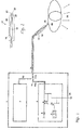
- the system according to the present invention comprises an HF generator 3, which generates an HF voltage by means of a switching transistor 5, a resonance transformer 6, the HF voltage being applied through a coaxial line 11 and a capacitor 18 with a small capacitance of approx an electrode 22 is passed. This electrode 22 is accommodated in a nozzle 23 at the end of the handpiece 17.
- an easily ionizable gas such as helium is passed from a storage container 2, not described here, through a gas supply line 12 in the handpiece cable 14 of the handpiece 17 into the handpiece 17.
- the gas connection 19 is connected to a metal tube 20 within the handpiece and has the gas openings 21 and the electrode 22 (FIG. 2).
- the gas flows out of the nozzle 23 via the gas openings 21. If the HF generator 3 is switched on, the HF current flows through the coaxial line 11, the handpiece cable 14 and the capacitor 18 to the electrode 22. If the HF voltage is sufficiently high, the electrode 22 and the tissue surface 29 are exposed treating patient a discharge 28.
- the HF current flows as a capacitive displacement current 30 from the patient to the earth and from the earth connection 31 back to the HF generator.
- a neutral electrode as is required in conventional HF surgery, is not required.
- Capacitor 18 in handpiece 17 limits the HF current to the maximum values of less than 150 mA valid for HF surgery (IEC 601-2-2).
- the presence of the capacitor 18, which together with the secondary winding of the resonance transformer 6 forms a resonance circuit, and the restriction of the HF current are of great importance in connection with the present invention.
- the relatively low HF current of approx. 20 to 100 mA causes only slight heating in the discharge channel. Due to the very small point of impact of the arc on the tissue (with impact areas of a few hundred micrometers) there is a very high current density locally that heats the tissue. This current density drops very little Distance from the point of impact of the arc to values that are not significant Heat the tissue more. Since the radio frequency essentially from A patient flows as a capacitive displacement current to the mass, becomes a current flow through the tissue and thus possible damage to deeper tissue layers avoided.
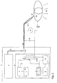
- FIG. 3 shows an oscillator 4, which has a rectangular voltage across the switching transistor 5 supplies.
- This switching transistor 5 turns on and sets the of the automatically controllable voltage source 8 and power consumption / limitation 7 delivered Voltage periodically to the primary winding of the resonance transformer 6.
- This resonance transformer 6 has a primary winding with approx. 3 to 30 turns and a secondary winding with 50 to 1000 turns (preferably 100 to 500), on one Ferrite core with an air gap are applied.
- the capacitance 15 (FIG. 3) of the coaxial line 11 forms in the handpiece cable 14 together with the secondary winding of the resonance transformer 6 a resonant circuit.
- the switching transistor 5 with the resonance frequency of the resonance transformer 6 is controlled, so supplies the secondary winding of the resonance transformer 6 a high sinusoidal RF voltage of 2000 to 4000 volts.
- the HF current flows through the capacitor 18 in the handpiece 17 to the electrode 22.
- An easily ionizable Gas such as helium becomes through the gas supply line 12 in the handpiece cable 14 to the electrode tip 22 passed, which sits in a nozzle 23 or can protrude from it.
- the high RF voltage creates a plasma discharge in the form of an electrical discharge (an arc) 28 against the patient's tissue surface 29.
- the patient educates the stray capacitance 16 existing relative to the ground.
- the HF current flows through it Stray capacitance and the ground potential back to the resonance transmitter 6th position 32 ( Figure 3) shows the schematic current profile.
- the impedance of the electrical discharge (arc) depends on the length of the Arc and on the amount of RF current.
- the electrical discharge impedance (of the arc) drops sharply at high current densities in the arc. Therefore the HF current must be limited. This is done through the impedance of the handpiece capacitor 18 ( Figures 1 and 2).
- Handpiece capacitor 18 will, depending on what is desired HF current, preferably with a capacity of 10 to 50 pF.
- At a generator frequency of approx. 350 kHz results in an impedance of approx. 9 to 45 kOhm.
- currents of approx. 65 to 330 mA flow. However only currents in the range between approx. 40 and 120 mA measured, since usually the Discharge (arc) impedance 28 is quite high.
- the high resonance quality of the resonance transformer 6 requires excitation with the exact resonance frequency. From the handpiece capacitor 18 and from the electrical Discharge (the arc) determined resonance frequency affects the resonance frequency of the resonance transmitter 6. This leads to a sharp drop in the resonance frequency at the time the plasma discharge begins. This resonance drop is depending on the discharge conditions within the discharge (arc) 28 different. For this reason, precise frequency control of the oscillator is important Ratio to the actual resonance frequency of the resonance transmitter 6 necessary. A deviation of the actual resonance frequency from the oscillator frequency is as Change in the phase angle between the oscillator signal and the signal at the Primary winding of resonance transformer 6 detectable.
- the phase comparison stage 10 compares the two phase angles in relation to each other and provides the actual one Value to the automatic frequency control circuit 9 ( Figure 3). The phase angle gives way from the predetermined value and does not exactly match the resonance frequency, the control signal corrects the oscillator frequency accordingly.
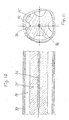
- the handpiece 17 is shown in detail in FIGS. 4 and 5.
- An easily ionizable Gas such as helium flows through a supply line 19 from the handpiece cable 14 into the metal tube 20.
- the easily ionizable gas escapes into the nozzle 23 at the gas opening 21 and leaves the handpiece 17 as a jet.
- the RF voltage supplied by the resonance transformer 6 flows through a coaxial line 11 in the handpiece cable to a metallized point 18a on an insulating layer through the dielectric 18b.
- So z. B. uses a silicone tube as a dielectric, which is pushed onto the metal tube 20.
- a thin metal foil e.g. a copper foil
- the inner conductor of the coaxial cable is in the Area 11a connected, e.g. by soldering.
- the insulating layer and the length of the metallization are so Capacities of approx. 2.5 to 150 pF can be achieved (preferably in the range between 5 and 50 pF).
- the current of the plasma discharge and thus the plasma power can be on the handpiece be adapted to requirements. Capacities of well over 50 pF will usually generate plasma currents of an intensity that is no longer surgical Applications are suitable.
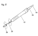
- the handpiece according to FIG. 8 has a construction similar to that in FIGS. 5, 6 and 7.
- the interchangeability of the nozzle 23 and the electrode 22 are advantages of the design according to FIG. 8.
- Figure 9 shows a handpiece with interchangeable adapters and / or tips.
- the inner one The structure is basically the same as in the embodiments according to FIGS. 5, 6, 7 and 8.
- the embodiment shown in Figure 9 has the advantage that application components different lengths and diameters can be attached.
- the endoscopy tip ( Figure 10) is a possible application part for the handpiece in Figure 9.
- the tubular tip contains an inner conductor 36 Transmission of the HF current.
- This inner conductor 36 sits in a core made of insulating Plastic 35.
- PTFE is particularly suitable for this purpose.
- This core is from one Surround plastic tube 33.
- the gas only flows in axial channels (see the section through the core in Figure 10) through the plastic tube 33.
- the gas flows through the axial channels 34 in which there is a low RF field strength.
- the gas flows into an inserted one Ceramic tube 37.
- the end of the inner conductor designed as an electrode tip 22 36 lies centrally in the ceramic tube 37.
- the discharge 28 in the direction of the tissue surface 29 happens from this top.
- the cavity is advantageous because of the necessary high-frequency voltages fill the handpiece with an insulating compound 25.
- the capacity between the electrical conductor and the electrode tip must be for the Endoscopy should be as small as possible so that the RF voltage does not drop too far because the rectilinear capacitance of the conductor to the surface of the tip or to the metal parts of the endoscope forms a voltage divider with the handpiece capacitor 18.
- the Discharge current can lead to image disturbances in camera endoscopes.
- the high field strength Another problem is in the area of the conductor, since ionization already occurs here can take place. Ionization occurs especially when using helium.
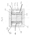
- FIG. 13 shows the resonance transformer as an air coil without a core.
- the air coil has a primary winding 40 with an approximate number of turns of 18 made from one relatively thick copper wire from 1 to 1.5 mm in diameter.
- the secondary winding consists of approx. 450 turns with a wire diameter of 0.2 mm.
- An insulating film 41 separates the primary from the secondary winding.
- the primary winding is 40a, 40b 1 or 3 connected to the switching transistor 5.
- the beginning of the Secondary winding 42a is connected to ground 31, while the end 42b of the secondary winding is connected to the coaxial line of the handpiece.
- a resonance frequency of approx. 350 kHz results in a capacity of the handpiece cable of approx. 200 pF.
- FIG. 14 shows a resonance transformer with a ferrite core.
- the two windings 40, 42 and the coil former 43 are seated here on a two-part ferrite core 44a, 44b.
- the Air gap 45 defines the magnetic resistance and inductance of the secondary coil and thus the resonance frequency of the system at a predetermined number of Secondary coil turns.
- the advantage of this arrangement according to FIG. 14 in comparison to that in Figure 13 is the lower number of turns of the secondary winding. About 75 turns on the secondary side are sufficient here.
- the Primary winding 40 consists of three turns of enamelled copper wire of 1 mm in diameter.
- the advantages of the present HF generator for surgical cuts are the resonance transmitter and the condenser housed in the handpiece. In contrast to the conventional one HF surgery generates small peak currents.
- the construction of the present Invention eliminates the need for a neutral electrode.
- the course of the HF current corresponds to that in FIGS. 1 and 3.
- the handpiece capacitor preferably has one Capacitance from approx. 5 to 50 pF to limit the HF current.
- the oscillator is on tuned a frequency that corresponds to the resonance frequency.
- the resonance transmitter is controlled by the switching transistor.
- the handpiece according to FIG. 15 shows a construction similar to that in FIGS. 5, 6, 7 and 8.
- the interchangeability of the nozzle and the electrode is through a quick release given that is easy and safe to use.
- the quick release will guaranteed by guide contours that continue in the longitudinal direction of the handpiece 17.
- a locking mechanism can be attached to after insertion the electrode tip 22 in the handpiece 17 to define an end position.
- FIG. 16 shows additional details of an electronic circuit for generation of high frequencies for a surgical plasma device.
- the frequency is roughly through the signal (FRQ) is preselected via the processor interface 101 according to FIG. 16 Interface 101 of the processor, which provides the analog and digital signals for parameter transfer is supplied by a microprocessor (CPU bus) via appropriate software controlled (not described here in detail).
- a microprocessor CPU bus
- This signal (FRQ) reaches the voltage-controlled oscillator 102.
- the output signal (HF-OUT) is processed in position 105, i.e. the output signal (HF-OUT) is integrated and limited and then fed to a phase comparator 106.
- Phase comparator 106 now compares the phases of the output signal from the Signal generation stage 105 with the phase of the oscillator 102 - signal OSZ - derived and then gives the phase difference as an analog voltage to the frequency controller 107 further.
- the frequency control now compares the phase signal with one predefined reference value and controls the frequency of the oscillator 102 with the help of the signal (FRQ-TUNE) to a frequency whose phase difference with the previous certain reference value of the frequency matches.
- the resonance transmitter will after this process tuned to the desired resonance frequency.
- the operating voltage U reaches the power pack through a current measuring unit 108 Power stage 104.
- Current measuring unit 108 sends signal I to current limiter stage 109 and thus prevents overloading of the power amplifier 104.
- the voltage U of the power supply is reduced accordingly by the control signal DOWN as soon as the signal I-max defined current is exceeded.
- the power measurement unit 110 multiplies the actual current 1a of the output stage by that at the Power stage applied operating voltage U and delivers the result, i.e. that of Power stage 4 absorbed power, to the power controller 111.
- the power controller 111 now compares the power signal P with that from the interface provided predefined value Pmax. If this is exceeded, the The power supply voltage is reduced by the control signal DOWN until the previously set one Performance is achieved.
- the switching transistor periodically applies the primary winding of the resonance transformer to the Supply voltage. This must be exactly in sync with the resonance frequency of the resonance transmitter 6 happen.
- the resonance frequency is chosen correctly when the actual voltage an opposite potential at the primary winding at switch-on torque for operating voltage.
- the phase difference between the control signal on Switching transistor and the RF signal at the resonance transformer 6 can therefore be considered a direct Criterion for the correct resonance frequency can be used.
- Resonance transformer 6 contains a primary winding with a few turns and one Secondary winding.
- the secondary winding is with a coaxial cable from the handpiece connector connected.
- the inductance of the secondary winding and the capacity of the coaxial cable form a resonant circuit, the HF generator at its resonant frequency must be coordinated.
- the outer conductor of the coaxial cable is additional grounded.
- the amplitude of the RF voltage at the primary winding of the resonance transformer corresponds at a correct resonance frequency approximately the operating voltage.
- the automatic Control of the RF output voltage is achieved by changing the operating voltage achieved.
- Automatic control and / or limitation of the output power is achieved by directly measuring the discharge power at the resonance transformer.
- the HF generator There is one between the HF generator and the resonance transformer Monitoring circuit that the achieved power of the RF voltage and other parameters measures, tests and monitors.
- the monitoring circuit switches the device off and issues an alarm if inadmissible deviations (e.g. in the Power discharge, the HF current and other parameters) can be detected.
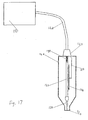
- An RF generator 121 is via a connector 123 and an RF connection cable 122 connected to a handpiece 124 with gas line.
- Handpiece 124 is connected to RF generator 121 via connecting cable 122; the RF generator 121 includes a coaxial cable and a helium gas line as well Control lines for the control button for switching on the device.
- Connection cable 122 is connected to an insulated gas pipe 130. This will be the first extended by a first condenser (position 127) which is a gas pipe owns. This first capacitor 127 is located centrally in the elongated, cylindrical one Handpiece 124.
- a capacitor 127, 128 is located in the handpiece 124, between the electrode tip and the inner conductor of the connecting cable 122. This capacitor 127, 128 limits the maximum HF current to values below a defined, predetermined Size of e.g. 150 mA, which is the maximum permissible current for HF surgery represents.
- Handpiece 124 tapers at its end and ends at connector 123; the other end carries a gas outlet opening / nozzle 125.
- the first condenser 127 extends on the outside of an electrode 126 which projects into the gas outlet opening / nozzle 125.
- a second capacitor part 128 lies opposite the first capacitor part 127.
- a connecting line 129 connects the connecting piece 123 to the second capacitor part 128.
- the electrode 126 and the gas outlet opening are located within a heat-resistant one Nozzle 125.
- the gas outlet opening and the electrode can also be used as a metal tube be formed.
- the plasma discharge (electric arc) begins this electrode.
- the capacitor can be constructed together with the electrode as one part become.
- the advantages of the system of the present invention for tissue coagulation are a very low penetration depth of the coagulation, very small RF current peaks (and thus greatly reduced current flow through the patient, since the patient is not connected to an ungrounded electrode must be connected), and clearly less damage to cells in the coagulation zone.
Abstract
Description
Die vorliegende Erfindung bezieht sich auf einen Plasmagenerator zur Erzeugung eines kalten Plasmastrahls für die Anwendung im medizinischen Bereich, insbesondere für chirurgische Anwendungen, sowie für andere Wissenschaftsbereiche.The present invention relates to a plasma generator for generating a cold plasma jets for use in the medical field, in particular for surgical Applications, as well as for other areas of science.
Plasmaquellen, die unter atmosphärischem Druck ein Plasma von mehr als 1000 Grad erzeugen können, sind allgemein üblich. Die Erwärmung des Plasmas geschieht durch konventionelle elektromagnetische Induktion, genauer: durch die induktive Erwärmung von elektrisch leitenden Medien im elektromagnetischen Wechselfeld einer Induktionsspule.Plasma sources that under atmospheric pressure have a plasma of more than 1000 degrees can generate are common. The plasma is heated by conventional electromagnetic induction, more precisely: through inductive heating of electrically conductive media in the alternating electromagnetic field of an induction coil.
Diese Plasmaquelle besteht aus einem Wechselstrom-Hochspannungsgenerator, einem röhrenförmigen Quarzbehälter und einer flüssigkeitsgekühlten Induktionsspule mit einer hohen Anzahl Windungen. Eine Spule mit einem Durchmesser von 10 cm ist unbedingt erforderlich, um eine Induktion in einem Volumen von 1 Liter zu erzeugen. Der Induktionswiderstand steigt bei Frequenzen von über 1 MHz sehr stark an. Im allgemeinen ist es schwierig, den Hochspannungsgenerator an den Induktionswiderstand anzupassen, da die effektive Ausgangsleistung dadurch verringert wird. Die Entwicklung einer Plasmaquelle nach den Erkenntnissen der Technik führt zu einer Verkleinerung der äußeren Abmessungen, aber auch zu einem geringeren Wirkungsgrad und zu höheren Plasmatemperaturen, was, insbesondere in den Bereichen der Medizin, Biologie und der Umweltanwendungen, den Einsatzbereich einschränkt.This plasma source consists of an alternating current high voltage generator, one tubular quartz container and a liquid cooled induction coil with a high number of turns. A coil with a diameter of 10 cm is essential required to produce an induction in a volume of 1 liter. The induction resistance increases very strongly at frequencies above 1 MHz. Generally is it is difficult to adapt the high voltage generator to the induction resistance, because it reduces the effective output power. The development of a plasma source according to the knowledge of technology leads to a reduction in the size of the external Dimensions, but also to lower efficiency and higher plasma temperatures, what, especially in the fields of medicine, biology and environmental applications, limits the area of application.
Andere Plasmageneratoren werden in elektrischen Entladungsapparaten verwendet, die mit einem elektronischen Oszillator, einer Modulationsstufe, einem Resonanzübertrager sowie einer stabförmigen Entladungselektrode ausgestattet sind. Ein Plasmastrahl wird hier zwischen dem Elektrodenende und dem Objekt erzeugt. Der elektronische Oszillator erzeugt Schwingungen in der Größenordnung von ca. 200 bis 300 kHz. Der Modulator schaltet das Oszillatorsignal in einem Frequenzbereich von 3 bis 5 kHz an und aus. Auf diese Weise sorgt der Modulator für eine verstärkte Erregung des Resonanzübertrager und des Objekts. Dieser Apparat hat einen günstigen therapeutischen Effekt bei der Behandlung von vielen Krankheiten, indem er verschiedenen Teilen des Körpers Wärme zuführt.Other plasma generators are used in electrical discharge devices that with an electronic oscillator, a modulation stage, a resonance transformer and a rod-shaped discharge electrode. A plasma beam will generated here between the electrode end and the object. The electronic oscillator generates vibrations in the range of approx. 200 to 300 kHz. The modulator switches the oscillator signal on and off in a frequency range of 3 to 5 kHz. On in this way, the modulator provides increased excitation of the resonance transmitter and the object. This device has a favorable therapeutic effect in the treatment from many diseases by giving heat to different parts of the body feeds.
Dieser Apparat besitzt jedoch nachteilige Eigenschaften: so wird die Umwandlung der Entladung von der Korona zur Funkengestalt sichtbar, und dabei führt der Leiter direkt in das Gewebe.However, this apparatus has disadvantageous properties: this is how the conversion of the Discharge from the corona to the spark shape is visible, and the conductor leads directly into it the mesh.
Die klassische Korona- und Funkenentladung führt unweigerlich zur Ionisierung, elektrischen Zerstörung und Erwärmung des Luftspalts zwischen der Elektrode und dem Körper, der die zweite Elektrode darstellt. Dadurch kommt es zu einer durch die Wärme verursachten, chaotischen Bewegung der Partikel in der Entladungszone.The classic corona and spark discharge inevitably leads to ionization, electrical Destruction and heating of the air gap between the electrode and the body, which is the second electrode. This creates a heat-induced chaotic movement of the particles in the discharge zone.
Die herkömmliche HF-Chirurgie verwendet einen HF-Frequenzgenerator für die Spraykoagulation
oder Argonkoagulation (Plasmaentladung innerhalb eines Argonstrahls). In diesem
Fall arbeitet der HF-Generator gemäß dem Prinzip der Stoßerregung von Schwingendkreisen.
Diese Impulserregung eines Schwingkreises erzeugt kurze HF-Impulse
(Bursts) mit einem, gemessen an der Impulsdauer langen, Pausenintervall (siehe Abb. 2).
Das Verhältnis Impulsdauer/Pausenintervall beträgt in der Regel zwischen 10 und 20
Prozent. Dadurch kommt es zu starken Spitzenleistungen während der Bursts und folglich
zu sehr hohen Spitzenströmen, die mehrere Ampere erreichen können. Die Kapazität
zwischen Patient und Erde ist unter diesen Umständen nicht ausreichend, um den
Stromkreis zu schließen und macht daher in der Regel bei konventioneller HF-Chirurgie
die Verwendung einer neutralen Elektrode nötig. Außerdem wird die Kontaktfläche des
Entladungsbogens auf das Gewebe relativ groß und kann mehrere Quadratmillimeter erreichen,
so daß die Durchdringungstiefe des Hitzeeffekts als sehr groß empfunden wird.
Außerdem führen Stromspitzen, die durch das Gewebe strömen, auch in tieferen Bereichen
zu einer hohen Strombelastung, die auf empfindliches Gewebe, wie z.B. Nervengewebe
im Gehirn, schädigend wirken kann. Das Spektrum eines HF-Stroms, der aus
kurzen Bursts besteht, enthält immer auch einen nicht zu unterschätzenden Faktor, der
sich aus der Pulswiederholfrequenz herleitet. Diese Frequenz liegt üblicherweise zwischen
10 und 70 kHz. Diese tiefen Frequenzen können Schäden an empfindlichem Gewebe
verursachen. Plasmageneratoren herkömmlicher Bauart, die das Plasma auf induktivem
Weg oder über eine Bogenentladung erzeugen, sind aufgrund ihrer Kühlanforderungen
für ein Handstück zu schwer. Außerdem erzeugen konventionelle Plasmageneratoren
sehr hohe Plasmatemperaturen von mehreren Tausend Grad Celsius als Wärmeplasma. Conventional HF surgery uses an HF frequency generator for spray coagulation or argon coagulation (plasma discharge within an argon beam). In this case, the HF generator works according to the principle of shock excitation of oscillating circuits. This pulse excitation of an oscillating circuit generates short RF pulses (bursts) with a long interval measured in terms of the pulse duration (see Fig. 2). The ratio of pulse duration / pause interval is usually between 10 and 20 percent. This leads to strong peak power during the bursts and consequently to very high peak currents that can reach several amperes. Under these circumstances, the capacity between patient and earth is not sufficient to close the circuit and therefore usually requires the use of a neutral electrode in conventional HF surgery. In addition, the contact area of the discharge arc on the tissue becomes relatively large and can reach several square millimeters, so that the depth of penetration of the heat effect is felt to be very large.
In addition, current peaks that flow through the tissue lead to a high current load in deeper areas, which can have a damaging effect on sensitive tissue, such as nerve tissue in the brain. The spectrum of an HF current, which consists of short bursts, always contains a factor that should not be underestimated, which is derived from the pulse repetition frequency. This frequency is usually between 10 and 70 kHz. These low frequencies can damage sensitive tissue. Conventional-type plasma generators that generate the plasma inductively or via an arc discharge are too heavy for a handpiece due to their cooling requirements. In addition, conventional plasma generators generate very high plasma temperatures of several thousand degrees Celsius as heat plasma.
Ein weiterer Plasmagenerator wird in dem europäischen Patentdokument EP-A 0837622 beschrieben. Dieser Generator enthält eine Spannungsquelle und einen elektrischen Oszillator, wobei der elektrische Oszillator von einem Verstärker versorgt wird, der an ein Niedervoltgerät angeschlossen ist, einem Resonanzübertrager mit einem Niederspannungseingang und einem Hochspannungsausgang und einer Verbindung des Hochspannungsausgangs des Resonanzübertragers mit der Entladungselektrode. Dieser Oszillator besitzt eine Rückkopplungswicklung, an der ein einstufiger Leistungsoszillator angeschlossen ist. Die sehr geringe Stabilität der Entladungsamplitude und die damit verbundenen Probleme der Leistungssteuerung sind in Zusammenhang mit einem solchen einstufigen Leistungsoszillator von Nachteil.Another plasma generator is described in European patent document EP-A 0837622 described. This generator contains a voltage source and an electrical oscillator, the electrical oscillator being powered by an amplifier connected to a Low voltage device is connected, a resonance transformer with a low voltage input and a high voltage output and a connection of the high voltage output of the resonance transformer with the discharge electrode. This oscillator has a feedback winding to which a single-stage power oscillator is connected is. The very low stability of the discharge amplitude and the associated Power control problems are associated with such a single stage Power oscillator disadvantageous.
Das US-Patent 4,781,175 (ausgestellt auf McGreevy und Andere) beschreibt die Anwendung eines elektrochirurgischen leitenden Gasstrahls zur Verbesserung der Schorfbildung für die Gerinnung. Ein vorab bestimmtes ionisierbares Gas wird dem Gewebe strahlförmig bei einer Durchflußmenge zugeführt, die zur Beseitigung natürlicher Flüssigkeiten vom Gewebe und zur Offenlegung des Gewebestroma ausreichend ist. Um eine Austrocknung zu erreichen, wird elektrische Energie als Lichtbögen in den ionisierten leitfähigen Bereichen zugeführt.U.S. Patent 4,781,175 (issued to McGreevy and others) describes the application an electrosurgical conductive gas jet to improve scab formation for coagulation. A predetermined ionizable gas becomes the tissue jet-shaped at a flow rate that is used to remove natural liquids of the tissue and for the disclosure of the tissue flow is sufficient. To one To achieve dehydration, electrical energy is used as arcs in the ionized conductive Areas fed.
Die europäische Patentanmeldung EP 0787465 A1 (ausgestellt auf Kim und Andere) beschreibt einen Kaltplasmakoagulator. Dieser Kaltplasmakoagulator besteht aus einem Hochfrequenznetzteil, einem Gasdynamikblock und einem Plasmotron. Das Netzteil besteht aus Gleichrichter, Kondensatorpuffer und einem Spannungsinverter. Ein Resonanzinduktor sowie ein nicht leitendes Rohr sind koaxial angeordnet, wobei das eine Ende des nicht leitenden Rohrs mit dem Gasdynamikblocks verbunden ist, während das andere Ende durch eine Düse Plasma ausstößt. Die Windungen des Resonanzinduktors bestehen aus einem Niederspannungs- und einem Hochspannungsteil. Das Niederspannungsteil der Resonanzspulen ist mit dem Ausgang des Spannungsinverters verbunden.European patent application EP 0787465 A1 (issued to Kim and others) describes a cold plasma coagulator. This cold plasma coagulator consists of a High-frequency power supply, a gas dynamic block and a plasmotron. The power supply is there consisting of rectifier, capacitor buffer and a voltage inverter. A resonance inductor and a non-conductive tube are arranged coaxially, with one end of the non-conductive tube is connected to the gas dynamic block, while the other End ejects plasma through a nozzle. The turns of the resonance inductor exist from a low voltage and a high voltage part. The low voltage part the resonance coils is connected to the output of the voltage inverter.
Das DDR-Patent 79087 (ausgestellt auf G. Pforr) beschreibt ein Gerät zum Betrieb eines induktiven Plasmabrenners. Ein von einem Hochfrequenzgenerator erzeugter hochfrequenter Wechselstrom wird einer Arbeitsspule zugeführt. Die Arbeitsspule ist beweglich und mit einem Leistungskoaxialkabel am Hochfrequenzgenerator angeschlossen. Innerhalb des Isolierrohrs der Arbeitsspule wird eine induktive Plasmaflamme erzeugt.The GDR patent 79087 (issued to G. Pforr) describes a device for operating a inductive plasma torch. A high frequency generated by a high frequency generator AC power is supplied to a work coil. The work spool is movable and connected to the high frequency generator with a power coaxial cable. Within An inductive plasma flame is generated in the insulating tube of the work coil.
Die europäische Patentanmeldung 0155496 (ausgestellt auf Peter Gagne) beschreibt eine Plasma-Emissionsquelle. Sie enthält einen HF-Leistungsgenerator, einen Plasmabrenner sowie Regler zur automatischen und ständigen Steuerung der vom Generator an die Lastspule geleiteten HF-Energie. Ein abstimmbarer Serien- bzw. Parallelkreis regelt die Impedanz des Leistungsgenerators bzw. der Lastspule. Jeder Kreis besitzt mindestens einen einstellbaren Kondensator und Einrichtungen zum Steuern der Kondensatoren. Diese bestehen aus primären und sekundären Motoren zum Steuern der erwähnten Kondensatoren sowie einem Detektor zur Lieferung von Eingangssignalen, die das Phasenverhältnis der HF-Spannung und des HF-Stroms widerspiegeln.European patent application 0155496 (issued to Peter Gagne) describes a plasma emission source. It contains an RF power generator, a plasma torch as well as controllers for automatic and constant control of the generator RF energy conducted to the load coil. A tunable series or parallel circuit regulates the impedance of the power generator or the load coil. Every district has at least an adjustable capacitor and devices for controlling the capacitors. These consist of primary and secondary motors for controlling the mentioned Capacitors and a detector for the delivery of input signals that the Reflect the phase relationship of the RF voltage and RF current.
Ein Handstück für chirurgische Schnitte mit einem Plasmastrahl wird im US-Patent
4,781,175 (ausgestellt auf Birtcher) beschrieben und besonders in den Figuren 6 bis 9
dargestellt.
Konventionelle HF-Chirurgieinstrumente liefern instabile Signale mit hohen Stromspitzen
von mehreren Ampere. Diese Stromspitzen konventioneller Geräte können aufgrund der
hohen Potentialunterschiede zwischen der Innenseite und der Außenseite der Zellmembran
auch in tiefergelegenen Gewebepartien Schäden verursachen.A handpiece for surgical cuts with a plasma jet is described in U.S. Patent 4,781,175 (issued to Birtcher) and particularly shown in Figures 6 to 9.
Conventional HF surgical instruments deliver unstable signals with high current peaks of several amperes. Due to the high potential differences between the inside and the outside of the cell membrane, these current peaks of conventional devices can also cause damage in lower tissue areas.
Die genannten Probleme bekannter Plasmageneratoren haben grundsätzlich zu einer Einschränkung der Verwendbarkeit der elektromagnetischen Technik in der Medizin, insbesondere der Chirurgie, geführt.The problems of known plasma generators mentioned basically have one Restriction of the usability of electromagnetic technology in medicine, in particular surgery.
Es ist Aufgabe der vorliegenden Erfindung, einen alternativen Plasmagenerator für chirurgische Anwendungen zu entwickeln, wobei dieser nicht die oben genannten Probleme konventioneller Plasmageneratoren aufweist.It is an object of the present invention to provide an alternative plasma generator for surgical Develop applications where this does not solve the problems mentioned above conventional plasma generators.
Außerdem soll mit der vorliegenden Erfindung eine Verschorfung mit einem chirurgischen Kaltplasmastrahlgerät erzeugt werden, die soweit wie möglich ohne Verkohlung oder Verbrennungsprodukte aufgrund von Sauerstoffeinschlüssen ist, wie dies in Verbindung mit der Argonplasma-Methode auftreten kann.In addition, the present invention is intended to provide a surgical scab Cold plasma jet device are generated as far as possible without charring or Combustion products due to oxygen inclusions are related to this can occur with the argon plasma method.
Diese und andere Faktoren und Vorteile der vorliegenden Erfindung werden durch die folgende Beschreibung erläutert.These and other factors and advantages of the present invention are demonstrated by the following description explains.
Die vorliegende Erfindung bezieht sich auf ein Kaltplasmagerät, das in der HF-Chirurgie zur Gerinnung von Gewebeoberflächen und zum abrasiven Entfernen von Gewebe verwendet wird.The present invention relates to a cold plasma device used in HF surgery used for coagulation of tissue surfaces and for abrasive removal of tissue becomes.
Das in der vorliegenden Erfindung beschriebene Kaltplasmagerät enthält einen HF-Generator, einen Resonanzübertrager, ein Handstück und eine Heliumgasquelle.The cold plasma device described in the present invention contains an HF generator, a resonance transmitter, a handpiece and a helium gas source.
Das Gerät dient zur Gerinnung von Gewebe durch Plasmaentladungen in Bereich der HF-Chirurgie. Aufbau und Funktionen sind wie folgt: ein HF-Generator sendet sein Signal an einen Resonanzübertrager. Der Resonanzübertrager transformiert das HF-Signal von ca. 350 kHz auf eine Spannung von ca. 2000 bis 3000 Volt. Der Ausgang dieses Resonanzübertragers (Sekundärwicklung) ist über eine Koaxialleitung mit integrierter Gasleitung zur Versorgung mit Helium mit einem Handstück verbunden. Der zweite Pol der Sekundärwicklung ist geerdet. Das Handstück besitzt eine Elektrodenspitze, die in einer Düse angeordnet ist, durch und um welche das Schutzgas Helium strömt. Diese Elektrodenspitze ist mit dem Leiter der Koaxialleitung verbunden, der über einen Kondensator die HF-Spannung zuführt. Wird der HF-Generator eingeschaltet, so findet eine sofortige Koronaentladung an der Elektrodenspitze innerhalb der Düse statt. Der Gasstrom treibt die Koronaentladung so durch die Düse nach außen, daß eine Flammenentladung in der Luft erfolgt. Wird diese Flamme gegen ein Gewebe gerichtet, so erfolgt eine Bogenentladung zum Gewebe, die mit einem entsprechenden Lichtbogen einhergeht. Die hohe Stromdichte am Auftreffpunkt sowie die Beschleunigung der Ladungsträger (Ionen) unmittelbar am Auftreffpunkt des elektrischen Lichtbogens bewirken eine Koagulation sowie ein Verdampfen des Gewebes, falls die Frequenz ausreichend hoch gewählt wurde.The device is used for the coagulation of tissue by plasma discharges in the area HF surgery. The structure and functions are as follows: an HF generator sends its signal to a resonance transformer. The resonance transformer transforms the RF signal from approx. 350 kHz to a voltage of approx. 2000 to 3000 volts. The output of this resonance transmitter (Secondary winding) is via a coaxial line with an integrated gas line connected to a handpiece to supply helium. The second pole of the secondary winding is grounded. The handpiece has an electrode tip that is in a Nozzle is arranged, through and around which the protective gas helium flows. This electrode tip is connected to the conductor of the coaxial line, via a capacitor supplies the RF voltage. If the HF generator is switched on, an immediate one is found Corona discharge takes place at the tip of the electrode inside the nozzle. The gas flow is driving the corona discharge through the nozzle so that a flame discharge in the Air takes place. If this flame is directed against a tissue, an arc discharge occurs to the tissue that is accompanied by an appropriate arc. The height Current density at the point of impact and the acceleration of the charge carriers (ions) immediately at the point of impact of the electric arc cause coagulation as well evaporation of the tissue if the frequency is chosen to be sufficiently high.
Der HF-Strom fließt dann als dielektrischer Verschiebungsstrom von der Oberfläche des Patienten nach Masse ab, solange der Patient nicht elektrisch geerdet ist. Eine neutrale Elektrode wird nicht verwendet, und auf diese Weise wird ein Stromfluß durch den Patienten verhindert oder zumindest wesentlich verringert. Der im Handstück eingebaute Kondensator beschränkt durch seine geringe Kapazität den HF-Strom auf Werte unter 150 mA und hält somit die Leckströme unterhalb der für die HF-Chirurgie maximal zulässigen Werte. Der Resonanzübertrager wird im Gegensatz zu konventionellen HF-Chirurgiegeräten nicht durch Impulse erregt, sondern die Erregung des Resonanzübertragers findet ständig statt. Dadurch erzeugt der Resonanzübertrager ein reines Sinussignal ohne die in konventionellen HF- Chirurgiegeräten üblichen hohen Stromspitzen von mehreren Ampere, und diese Signale verursachen auch keinerlei Schädigung von tiefergelegenen Gewebepartien.The RF current then flows as a dielectric displacement current from the surface of the Reduce patient weight as long as the patient is not electrically grounded. A neutral one Electrode is not used and in this way there is a flow of current through the patient prevented or at least significantly reduced. The one built into the handpiece Due to its low capacitance, the capacitor limits the HF current to values below 150 mA and thus keeps the leakage currents below the maximum permissible for HF surgery Values. The resonance transmitter is used in contrast to conventional HF surgical devices not excited by impulses, but the excitation of the resonance transmitter takes place constantly. As a result, the resonance transformer generates a pure sine signal without the high current peaks that are common in conventional HF surgical devices of several amperes, and these signals also do not cause any damage to lower tissue areas.
Der Schneideffekt in der HF-Chirurgie basiert auf dem Prinzip des Zellrisses. Die erzielten Schnitte sind als glatt, koagulationsreich und verschorft zu bezeichnen.The cutting effect in HF surgery is based on the principle of cell rupture. The achieved Cuts can be described as smooth, rich in coagulation and scabbed.
Ein glatter Schnitt in der HF-Chirurgie ist weitgehend mit einem durch ein Skalpell erzielten Schnitt vergleichbar, d.h. die Schnittflächen sind nur wenig verfärbt. Der Schnittyp des glatten Schnitts wird mit einem unmodulierten HF-Strom und bei schneller Durchführung des Schnitts erzielt.A smooth cut in HF surgery is largely achieved with a scalpel Cut comparable, i.e. the cut surfaces are only slightly discolored. The cut type The smooth cut is made with an unmodulated HF current and when carried out quickly of the cut.
Eine Verringerung der Schnittgeschwindigkeit hat einen Schnitt mit stärkerer Koagulation bzw. einen Schnitt mit Schorf zu Folge. Das gleiche Ergebnis wird erreicht, wenn ein pulsmodulierter HF-Strom der gleichen durchschnittlichen Leistung verwendet wird. A reduction in the cutting speed has a cut with more coagulation or a cut with scab. The same result is achieved when a pulse modulated RF current of the same average power is used.
Die für die Durchführung eines HF-Schnitts notwendige Leistung hängt von der Form der Elektrode, dem Gewebetyp sowie dessen Widerstand ab. Ist die Leistung zu gering, findet kein Zellriss statt, und das Gewebe bleibt an der Elektrode kleben. Ist die Leistung zu hoch, können Funkenentladungen an der Elektrode und im Gewebe stattfinden, was eine Verkohlung der geschnittenen Oberflächen zur Folge hat.The power required to perform an RF cut depends on the shape of the Electrode, the type of tissue and its resistance. If the performance is too low, find there is no cell tear and the tissue sticks to the electrode. The performance is too high, spark discharges can occur on the electrode and in the tissue, which is a Charring the cut surfaces results.
Das Gewebe wird mehr oder weniger soweit erwärmt, daß für die Koagulation kein Zellriß stattfindet. Die Koagulationstemperatur liegt bei über 50 °C. Diese Temperatur führt zur Koagulation des innerhalb und außerhalb der Zelle befindlichen Zelleiweißes durch Verkochen des Gewebes. Verletzte Blutgefäße ziehen sich soweit zusammen, daß sie vollständig verschlossen werden und kein Blut austritt. Um diesen Effekt zu erzielen, muß ein elektrischer Strom das Gewebe genügend langsam erwärmen, so daß die Flüssigkeiten innerhalb und außerhalb der Zelle verdampft werden, ohne daß die Zellmembranen Schaden nehmen. Die Zellen ziehen sich aufgrund des Flüssigkeitsverlusts zusammen und die Zellwände werden zusammengeschweißt. Diese Art der Koagulation wird häufig Kontaktkoagulation genannt, weil die Elektroden in direkten Kontakt mit dem Gewebe gebracht werden. Eine Zufuhr von HF-Strom verursacht eine leichte Verfärbung des Gewebes sowie aufgrund der Eiweißgerinnung ein Ausfließen von Gewebeflüssigkeit.The tissue is more or less heated to the extent that there is no cell tear for the coagulation takes place. The coagulation temperature is over 50 ° C. This temperature leads to Coagulation of the cell protein inside and outside the cell by boiling of the fabric. Injured blood vessels contract so far that they are complete be closed and no blood leaks. To achieve this effect, must an electric current heats the tissue slowly enough so that the fluids can be vaporized inside and outside the cell without the cell membranes Get damaged. The cells contract due to the loss of fluid and the cell walls are welded together. This type of coagulation is common Contact coagulation is called because the electrodes are in direct contact with the tissue to be brought. A supply of HF current causes a slight discoloration of the tissue as well as an outflow of tissue fluid due to protein coagulation.
Die vorliegende Erfindung besitzt einen separaten Oszillator, der für die' Frequenz des Plasmagenerators zur Erzeugung eines kalten Plasmastrahls verwendet wird; dieser Oszillator steuert eine Leistungsendstufe.The present invention has a separate oscillator, which for the 'frequency of Plasma generator is used to generate a cold plasma jet; this oscillator controls a power amplifier.
Eine Ausführung des Plasmagenerators besteht darin, daß das Ausgangssignal der als Schalter arbeitenden Endstufe der Primärwicklung des Resonanzübertragers zugeführt wird.An embodiment of the plasma generator is that the output signal as Switch working output stage of the primary winding of the resonance transformer becomes.
Eine weitere Eigenschaft des Plasmagenerators besteht darin, daß die Phasendifferenz zwischen dem Oszillatorsignal und dem Ausgangssignal der Endstufe an der Primärwicklung zur Einstellung der Oszillatorfrequenz gemessen wird.Another property of the plasma generator is that the phase difference between the oscillator signal and the output signal of the output stage at the primary winding to adjust the oscillator frequency is measured.
Eine weitere Ausführung des Gegenstands der vorliegenden Erfindung enthält ein Steuersystem, mit dem die Oszillatorfrequenz durch das Steuersystem relativ zur Resonanzfrequenz des Resonanzübertragers abgestimmt wird.Another embodiment of the subject of the present invention includes a control system with which the oscillator frequency by the control system relative to the resonance frequency of the resonance transmitter is tuned.
Zusätzlich enthält der Plasmagenerator eine automatische Steuerung der Hochfrequenzleistung durch Veränderung der Betriebsspannung; hierbei wird die Leistung durch Multiplikation des Eingangsstroms mit der Eingangsspannung an der Endstufe ermittelt. In addition, the plasma generator contains an automatic control of the high-frequency power by changing the operating voltage; Here the performance is multiplied of the input current with the input voltage at the output stage.
Ausführungsformen, die als für diese Erfindung charakteristisch angesehen werden, sind in den beigefügten Ansprüchen beschrieben. Die Erfindung selbst in ihrer Konstruktion und Wirkungsweise sowie den zusätzliche Komponenten und deren Vorzügen kann jedoch am besten durch die folgende Beschreibung der einzelnen Ausführungen in Zusammenhang mit der entsprechenden Zeichnung verstanden werden.Embodiments that are considered characteristic of this invention are described in the appended claims. The invention itself in its construction and mode of action as well as the additional components and their advantages can best related to the following description of the individual statements can be understood with the corresponding drawing.
Die beigefügten Zeichnungen zeigen mögliche Ausführungsbeispiele der vorliegenden Erfindung:, es zeigt:
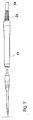
Figur 1- zeigt ein Schaltbild einer ersten Ausführung des Plasmagenerators und des Handstücks,
Figur 2- zeigt eine Detailansicht des Handstücks gemäß Figur 1,
- Figur 3
- zeigt ein Schaltbild einer zweiten Ausführung des Plasmagenerators mit ei- nem Handstück,
- Figur 4
- zeigt den Schnitt durch ein erstes Handstück,
Figur 5- zeigt den Schnitt durch die Elektrodenspitze im Handstück,
- Figur 6
- zeigt den Schnitt durch ein schräges Metallrohr mit einer Gasentladung, wobei das Metallrohr gleichzeitig als Elektrode dient,
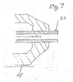
Figur 7- zeigt den Schnitt durch ein gerades Metallrohr mit einer Gasentladung, wobei das Metallrohr gleichzeitig als Elektrode dient,
Figur 8- ist eine perspektivische Explosionszeichnung des Handstücks mit einer Schraubverbindung gemäß vorliegender Erfindung,
Figur 9- ist ein seitliche Explosionszeichnung des Handstücks mit auswechselbarer Spitze,
Figur 10- zeigt den Schnitt durch eine erste Spitze für die Endoskopie,
Figur 11- zeigt den Schnitt durch eine erste Spitze für die
Endoskopie gemäß Figur 10, Figur 12- zeigt den Schnitt durch eine zweite Spitze für die Endoskopie,
- Figur 13
- zeigt den Schnitt durch den Resonanzübertrager,
Figur 14- zeigt den Schnitt durch den Resonanzübertrager zusammen mit einem Ferrit- kem,
Figur 15- ist eine perspektivische Explosionszeichnung eines Handstücks gemäß vor- liegender Erfindung, ähnlich der Konstruktion gemäß Figur 8, aber mit Steck- verbindung,
Figur 16- ist ein Blockschaltbild des Plasmagenerators,
Figur 17- zeigt den Anschluß und die Konstruktion des chirurgischen Plasmastrahl- Handstücks.
- Figure 1
- shows a circuit diagram of a first embodiment of the plasma generator and the handpiece,
- Figure 2
- 1 shows a detailed view of the handpiece according to FIG. 1,
- Figure 3
- shows a circuit diagram of a second embodiment of the plasma generator with a handpiece,
- Figure 4
- shows the section through a first handpiece,
- Figure 5
- shows the section through the electrode tip in the handpiece,
- Figure 6
- shows the section through an oblique metal tube with a gas discharge, the metal tube also serving as an electrode,
- Figure 7
- shows the section through a straight metal tube with a gas discharge, the metal tube also serving as an electrode,
- Figure 8
- 3 is an exploded perspective view of the handpiece with a screw connection according to the present invention,
- Figure 9
- is an exploded side view of the handpiece with replaceable tip,
- Figure 10
- shows the section through a first tip for endoscopy,
- Figure 11
- shows the section through a first tip for the endoscopy according to FIG. 10,
- Figure 12
- shows the section through a second tip for endoscopy,
- Figure 13
- shows the section through the resonance transmitter,
- Figure 14
- shows the section through the resonance transformer together with a ferrite core,
- Figure 15
- 3 is an exploded perspective view of a handpiece according to the present invention, similar to the construction according to FIG. 8, but with a plug connection,
- Figure 16
- is a block diagram of the plasma generator,
- Figure 17
- shows the connection and construction of the surgical plasma jet handpiece.
Der HF-Generator gemäß der vorliegenden Erfindung wird direkt mit einem Resonanzübertrager
verbunden. Der HF-Generator enthält einen Schalttransistor, der die Betriebsspannung
an der Primärwicklung des Resonanzübertragers periodisch unterbricht, eine
automatische Einrichtung, die die Schaltfrequenz des Transistors an die Resonanzfrequenz
des Resonanzübertragers anpaßt, und eine Einrichtung, mit der die elektrische
Entladung am Resonanzübertrager für die automatische Steuerung und Begrenzung der
Ausgangsleistung durch Verändern der Betriebsspannung gemessen werden kann.
Die Anlage gemäß vorliegender Erfindung umfaßt einen HF-Generator 3, der eine HF-Spannung
mittels eines Schalttransistors 5 erzeugt, einen Resonanzübertrager 6, wobei
die HF-Spannung durch eine Koaxialleitung 11 und einen Kondensator 18 mit kleiner Kapazität
von ca. 5 bis 50pF an eine Elektrode 22 geleitet wird. Diese Elektrode 22 ist in
einer Düse 23 am Ende des Handstücks 17 untergebracht. Gleichzeitig wird ein leicht
ionisierbares Gas wie Helium von einem hier nicht beschriebenen Vorratsbehälter 2
durch eine Gaszuleitung 12 im Handstückkabel 14 des Handstücks 17 in das Handstück
17 geleitet. Der Gasanschluß 19 ist innerhalb des Handstücks mit einem Metallrohr 20
verbunden und besitzt die Gasöffnungen 21 sowie die Elektrode 22 (Figur 2). Das Gas
strömt über die Gasöffnungen 21 aus der Düse 23 heraus. Wird der HF-Generator 3 eingeschaltet,
so fließt der HF-Strom durch die Koaxialleitung 11, das Handstückekabel 14
und den Kondensator 18 zur Elektrode 22. Ist die HF-Spannung genügend hoch, so erfolgt
zwischen der Elektrode 22 und der Gewebeoberfläche 29 des zu behandelnden Patienten
eine Entladung 28. Der HF-Strom fließt als ein kapazitiver Verschiebestrom 30
vom Patienten zur Erde und von der Erdverbindung 31 zurück zum HF-Generator. Eine
neutrale Elektrode, wie sie bei der herkömmlichen HF-Chirurgie benötigt wird, ist nicht
erforderlich. Durch die spezifische Konstruktion des HF-Generators mit einem Resonanzübertrager
6 bildet dessen sekundäre Wicklung mit der Kapazität der Koaxialleitung 11
einen parallelen Schwingkreis und so eine nahezu sinusförmige HF-Spannung, indem
der Schalttransistor 5 mit der Resonanzfrequenz des Resonanzübertragers 6 gesteuert
wird. Kondensator 18 im Handstück 17 begrenzt den HF-Strom auf die für die HF-Chirurgie
gültigen maximalen Werte von weniger als 150 mA (IEC 601-2-2). Das Vorhandensein
des Kondensators 18, der zusammen mit der Sekundärwicklung des Resonanzübertragers
6 einen Resonanzkreis bildet, sowie die Beschränkung des HF-Stroms sind
im Zusammenhang mit der vorliegenden Erfindung von großer Bedeutung.The RF generator according to the present invention is connected directly to a resonance transmitter. The HF generator contains a switching transistor which periodically interrupts the operating voltage at the primary winding of the resonance transmitter, an automatic device which adjusts the switching frequency of the transistor to the resonance frequency of the resonance transmitter, and a device with which the electrical discharge at the resonance transmitter is used for automatic control and limitation of the output power can be measured by changing the operating voltage.
The system according to the present invention comprises an HF generator 3, which generates an HF voltage by means of a switching
Der verhältnismäßig geringe HF-Strom von ca. 20 bis 100 mA (je nach Kapazität des im Handstück eingebauten Kondensators 18) verursacht nur eine leichte Erwärmung in Entladungskanal. Aufgrund des sehr kleinen Auftreffpunkts des Lichtbogens auf das Gewebe (mit Auftreffflächen von wenigen Hundert Mikrometern) wird lokal eine sehr hohe Stromdichte erzeugt, die das Gewebe stark erhitzt. Diese Stromdichte sinkt bereits in sehr kleinem Abstand vom Auftreffpunkt des Lichtbogens auf Werte ab, die zu keiner nennenswerten Erhitzung des Gewebes mehr führen. Da die Hochfrequenz im wesentlichen vom Patienten als kapazitiver Verschiebestrom nach Masse hin abfließt, wird ein Stromfluß durch das Gewebe und damit eine mögliche Schädigung von tieferen Gewebeschichten vermieden.The relatively low HF current of approx. 20 to 100 mA (depending on the capacity of the im Handpiece built-in capacitor 18) causes only slight heating in the discharge channel. Due to the very small point of impact of the arc on the tissue (with impact areas of a few hundred micrometers) there is a very high current density locally that heats the tissue. This current density drops very little Distance from the point of impact of the arc to values that are not significant Heat the tissue more. Since the radio frequency essentially from A patient flows as a capacitive displacement current to the mass, becomes a current flow through the tissue and thus possible damage to deeper tissue layers avoided.
Wird der elektrische Lichtbogen in schneller Abfolge über die Gewebeoberfläche bewegt, so erfolgt die Koagulation nur mit einer geringen Eindringtiefe. Eine punktförmige Anwendung, bei der die Entladung (der Lichtbogen) im wesentlichen auf die selbe Stelle auftrifft, führt zu einer so starken Erwärmung des Gewebes, daß das Gewebe praktisch verdampft. Mit dieser Methode kann Gewebe an der Oberfläche von Gewebe verdampft werden.If the electric arc is moved over the tissue surface in rapid succession, so the coagulation takes place only with a small penetration depth. A punctiform application, where the discharge (the arc) essentially strikes the same point, leads to such a strong heating of the tissue that the tissue practically evaporates. This method allows tissue to evaporate on the surface of tissue become.
In Figur 3 ist ein Oszillator 4 abgebildet, der eine rechteckförmige Spannung an Schalttransistor
5 liefert. Dieser Schalttransistor 5 schaltet durch und legt die von der automatisch
steuerbaren Spannungsquelle 8 und Leistungsaufnahme/-begrenzung 7 gelieferte
Spannung periodisch an die Primärwicklung des Resonanzübertragers 6. Dieser Resonanzübertrager
6 besitzt eine Primärwicklung mit ca. 3 bis 30 Windungen sowie eine Sekundärwicklung
mit 50 bis 1000 Windungen (vorzugsweise 100 bis 500), die auf einen
Ferritkern mit Luftspalt aufgebracht sind. Die Kapazität 15 (Figur 3) der Koaxialleitung 11
im Handstückkabel 14 bildet zusammen mit der Sekundärwicklung des Resonanzübertragers
6 einen Resonanzkreis. Wird der Schalttransistor 5 mit der Resonanzfrequenz
des Resonanzübertragers 6 angesteuert, so liefert die Sekundärwicklung des Resonanzübertragers
6 eine hohe sinusförmige HF-Spannung von 2000 bis 4000 Volt. Der HF-Strom
fließt über den Kondensator 18 im Handstück 17 zur Elektrode 22. Ein leicht ionisierbares
Gas wie Helium wird durch die Gaszuleitung 12 im Handstückkabel 14 zur Elektrodenspitze
22 geleitet, die in einer Düse 23 sitzt oder aus ihr hervorragen kann. Die
hohe HF-Spannung erzeugt eine Plasmaentladung in Form einer elektrischen Entladung
(eines Lichtbogens) 28 gegen die Gewebeoberfläche 29des Patienten. Der Patient bildet
die relativ zur Masse bestehende Streukapazität 16. Der HF-Strom fließt durch diese
Streukapazität und das Massepotential zurück zum Resonanzübertrager 6. Position 32
(Figur 3) zeigt den schematischen Stromverlauf.FIG. 3 shows an oscillator 4, which has a rectangular voltage across the switching
Die Impedanz der elektrischen Entladung (des Lichtbogens) hängt von der Länge des
Lichtbogens und von der Höhe des HF-Stromes ab. Die Impedanz der elektrischen Entladung
(des Lichtbogens) fällt bei hohen Stromdichten im Lichtbogen stark ab. Daher
muß der HF-Strom begrenzt werden. Dies geschieht durch die Impedanz des Handstückkondensators
18 (Figuren 1 und 2). Handstückkondensator 18 wird, je nach gewünschtem
HF-Strom, mit einer Kapazität von vorzugsweise 10 bis 50 pF geliefert. Bei einer Generatorfrequenz
von ca. 350 kHz ergibt sich damit eine Impedanz von ca. 9 bis 45 kOhm.
Bei einer Spannung von 3000 Volt fließen Ströme von ca. 65 bis 330 mA. Allerdings werden
nur Ströme im Bereich zwischen ca. 40 und 120 mA gemessen, da üblicherweise die
Impedanz der Entladung (des Lichtbogens) 28 recht hoch ist.The impedance of the electrical discharge (arc) depends on the length of the
Arc and on the amount of RF current. The electrical discharge impedance
(of the arc) drops sharply at high current densities in the arc. Therefore
the HF current must be limited. This is done through the impedance of the handpiece capacitor
18 (Figures 1 and 2).
Die große Resonanzgüte des Resonanzübertragers 6 erfordert eine Anregung mit der
exakten Resonanzfrequenz. Die vom Handstückkondensator 18 und von der elektrischen
Entladung (dem Lichtbogen) bestimmte Resonanzfrequenz beeinflußt die Resonanzfrequenz
des Resonanzübertragers 6. Dies führt zu einem starken Abfall der Resonanzfrequenz
zu dem Zeitpunkt, an dem die Plasmaentladung beginnt. Dieser Resonanzabfall ist
je nach den Entladungsbedingungen innerhalb der Entladung (des Lichtbogens) 28 unterschiedlich.
Aus diesem Grund ist eine genaue Frequenzsteuerung des Oszillators im
Verhältnis zur tatsächlichen Resonanzfrequenz des Resonanzübertragers 6 notwendig.
Eine Abweichung der tatsächlichen Resonanzfrequenz von der Oszillatorfrequenz ist als
Änderung des Phasenwinkels zwischen dem Oszillatorsignal und dem Signal an der
Primärwicklung von Resonanzübertrager 6 nachweisbar. Die Phasenvergleichsstufe 10
vergleicht die beiden Phasenwinkel im Verhältnis zueinander und liefert den tatsächlichen
Wert an den automatischen Frequenzsteuerkreis 9 (Figur 3). Weicht der Phasenwinkel
vom vorherbestimmten Wert ab und stimmt nicht exakt mit der Resonanzfrequenz überein,
so wird die Oszillatorfrequenz durch das Steuersignal entsprechend korrigiert.The high resonance quality of the resonance transformer 6 requires excitation with the
exact resonance frequency. From the
Wenn an den Lichtbogen (die Entladung) 28 eine hohe elektrische Leistung geliefert
wird, so steigt auch die Leistungsaufnahme der Endstufe einschließlich Schalttransistor 5
(Figuren 1 und 3). Ein Übersteigen des Grenzwertes für den HF-Strom durch Betriebsbedingungen
des Geräts, die hier nicht näher erläutert werden, führt durch ein Steuersignal
zu einer Verringerung des Gleichstroms, der von der automatisch steuerbaren Spannungsquelle
8 geliefert wird.When high electrical power is supplied to the arc (discharge) 28
, the power consumption of the output stage including switching
Das Handstück 17 wird in den Figuren 4 und 5 ausführlich dargestellt. Ein leicht ionisierbares
Gas wie Helium strömt durch eine Zuleitung 19 vom Handstückkabel 14 in das Metallrohr
20. Das leicht ionisierbare Gas entweicht an der Gasöffnung 21 in die Düse 23
und verläßt das Handstück 17 als Strahl.The
Die vom Resonanzübertrager 6 gelieferte HF-Spannung fließt durch eine Koaxialleitung
11 im Handstückkabel zu einer metallisierten Stelle 18a auf einer Isolierschicht, gebildet
durch das Dielektrikum 18b. So wird z. B. ein Silikonschlauch als Dielektrikum verwendet,
das auf das Metallrohr 20 geschoben wird. Eine dünne Metallfolie (z.B. eine Kupferfolie)
kann als Metallisierung dienen 18a (Figur 4). Der Innenleiter des Koaxialkabels wird im
Bereich 11a angeschlossen, z.B. durch Löten.The RF voltage supplied by the resonance transformer 6 flows through a
Die Metallisierung 18a auf dem Dielektrikum 18b (Figur 5) bildet zusammen mit dem Metallrohr
20 einen Kondensator (= Handstückkondensator 18), wobei dieser vorerwähnte
Kondensator zur Begrenzung des Plasma-Entladungsstroms dient. Je nach Konstruktion
und Größe des Metallrohrs, der Isolierschicht und der Länge der Metallisierung sind so
Kapazitäten von ca. 2,5 bis 150 pF erreichbar (vorzugsweise im Bereich zwischen 5 und
50 pF). Der Strom der Plasmaentladung und somit die Plasmaleistung kann am Handstück
den Erfordernissen angepaßt werden. Kapazitäten von weitaus mehr als 50 pF
werden in der Regel Plasmaströme von einer Intensität erzeugen, die nicht mehr für chirurgische
Anwendungen geeignet sind.The
Das Handstück gemäß Figur 8 besitzt eine Konstruktion ähnlich der in den Figuren 5, 6
und 7. Die Austauschbarkeit der Düse 23 und der Elektrode 22 sind Vorteile der Ausführung
gemäß Figur 8.The handpiece according to FIG. 8 has a construction similar to that in FIGS. 5, 6
and 7. The interchangeability of the
Ein Handstück mit auswechselbaren Adaptern und/oder Spitzen zeigt Figur 9. Der innere Aufbau ist grundsätzlich der gleiche wie in den Ausführungen gemäß den Figuren 5, 6, 7 und 8. Die in Figur 9 gezeigte Ausführung hat den Vorteil, daß Anwendungskomponenten verschiedener Längen und Durchmesser aufgesteckt werden können. Für die Verbindung zwischen dem Teil, das die Elektrodenspitze trägt, und dem Handstück wird eine Schraubkupplung verwendet. Die Endoskopiespitze (Figur 10) ist ein mögliches Anwendungsteil für das Handstück in Figur 9.Figure 9 shows a handpiece with interchangeable adapters and / or tips. The inner one The structure is basically the same as in the embodiments according to FIGS. 5, 6, 7 and 8. The embodiment shown in Figure 9 has the advantage that application components different lengths and diameters can be attached. For the connection between the part that carries the electrode tip and the handpiece Screw coupling used. The endoscopy tip (Figure 10) is a possible application part for the handpiece in Figure 9.
Nach den Figuren 10, 11 und 12 enthält die röhrenförmige Spitze einen Innenleiter 36 zur
Weiterleitung des HF-Stroms. Dieser Innenleiter 36 sitzt in einen Kem aus isolierendem
Kunststoff 35. PTFE ist besonders für diesen Zweck geeignet. Dieser Kern ist von einem
Kunststoffrohr 33 umgeben. Das Gas fließt nur in Axialkanälen (siehe den Schnitt durch
den Kem in Figur 10) durch das Kunststoffrohr 33. Das Gas strömt dabei durch die Axialkanäle
34, in denen eine niedrige HF-Feldstärke vorherrscht. Das Gas strömt in ein eingesetztes
Keramikrohr 37. Das Ende des als Elektrodenspitze 22 ausgebildeten Innenleiters
36 liegt zentrisch in dem Keramikrohr 37. Die Entladung 28 in Richtung Gewebeoberfläche
29 geschieht von dieser Spitze aus.According to FIGS. 10, 11 and 12, the tubular tip contains an
Es ist aufgrund der notwendigen hochfrequenten Spannungen von Vorteil, den Hohlraum
des Handstücks mit einer Isoliermasse 25 auszufüllen.The cavity is advantageous because of the necessary high-frequency voltages
fill the handpiece with an insulating
Die Kapazität zwischen dem elektrischen Leiter und der Elektrodenspitze muß für die
Endoskopie so klein wie möglich sein, damit die HF-Spannung nicht zu weit absinkt, weil
die geradlinige Kapazität des Leiters zur Oberfläche der Spitze oder zu den Metallteilen
des Endoskops einen Spannungsteiler mit dem Handstückkondensator 18 bildet. Der
Entladungsstrom kann bei Kamera-Endoskopen zu Bildstörungen führen. Die hohe Feldstärke
im Bereich des Leiters ist ein weiteres Problem, da bereits hier eine lonisierung
stattfinden kann. Ionisierung tritt besonders bei der Verwendung von Helium auf.The capacity between the electrical conductor and the electrode tip must be for the
Endoscopy should be as small as possible so that the RF voltage does not drop too far because
the rectilinear capacitance of the conductor to the surface of the tip or to the metal parts
of the endoscope forms a voltage divider with the
Die Konstruktion gemäß Figuren 10, 11 und 12 verringert den Effekt von Entladungsströmen auf vertretbar kleine Werte.The construction according to Figures 10, 11 and 12 reduces the effect of discharge currents to reasonably small values.
Figur 13 zeigt den Resonanzübertrager als Luftspule ohne Kern. Die Luftspule besitzt
eine Primärwicklung 40 mit einer ungefähren Windungszahl von 18, hergestellt aus einem
relativ dicken Kupferiackdraht von 1 bis 1,5 mm Durchmesser. Die Sekundärwicklung
besteht aus ca. 450 Windungen mit einem Drahtdurchmesser von 0,2 mm. Eine Isolierfolie
41 trennt die Primär- von der Sekundärwicklung. Die Primärwicklung 40a, 40b ist
gemäß Figur 1 oder Figur 3 an den Schalttransistor 5 angeschlossen. Der Anfang der
Sekundärwicklung 42a liegt an Masse 31, während das Ende 42b der Sekundärwicklung
mit der Koaxialleitung des Handstücks verbunden ist. Eine Resonanzfrequenz von ca.
350 kHz ergibt eine Kapazität des Handstückekabels von ca. 200 pF.FIG. 13 shows the resonance transformer as an air coil without a core. The air coil has
a primary winding 40 with an approximate number of turns of 18 made from one
relatively thick copper wire from 1 to 1.5 mm in diameter. The secondary winding
consists of approx. 450 turns with a wire diameter of 0.2 mm. An insulating
Figur 14 zeigt einen Resonanzübertrager mit einem Ferritkem. Die zwei Wicklungen 40,
42 sowie der Spulenkörper 43 sitzen hier auf einem zweiteiligen Ferritkem 44a, 44b. Der
Luftspalt 45 definiert den magnetischen Widerstand und die Induktivität der Sekundärspule
und damit die Resonanzfrequenz des Systems bei einer vorbestimmten Anzahl von
Windungen der Sekundärspule. Der Vorteil dieser Anordnung gemäß Figur 14 im Vergleich
zu der in Figur 13 besteht in der niedrigeren Anzahl der Windungen der Sekundärwicklung.
Hier sind ungefähr 75 Windungen auf der Sekundärseite ausreichend. Die
Primärwicklung 40 besteht aus drei Windungen Kupferlackdraht von 1 mm Durchmesser.FIG. 14 shows a resonance transformer with a ferrite core. The two
Die Vorteile des vorliegenden HF-Generators für chirurgische Schnitte sind der Resonanzübertrager und der im Handstück untergebrachte Kondensator. Im Gegensatz zur herkömmlichen HF-Chirurgie werden kleine Spitzenströme erzeugt. Die Konstruktion der vorliegenden Erfindung macht eine Neutralelektrode überflüssig. Der Lauf des HF-Stroms entspricht dem in den Figuren 1 und 3. Der Handstückkondensator hat vorzugsweise eine Kapazität von ca. 5 bis 50 pF zur Begrenzung des HF-Stroms. Der Oszillator wird auf eine Frequenz abgestimmt, die der Resonanzfrequenz entspricht. Der Resonanzübertrager wird vom Schalttransistor angesteuert.The advantages of the present HF generator for surgical cuts are the resonance transmitter and the condenser housed in the handpiece. In contrast to the conventional one HF surgery generates small peak currents. The construction of the present Invention eliminates the need for a neutral electrode. The course of the HF current corresponds to that in FIGS. 1 and 3. The handpiece capacitor preferably has one Capacitance from approx. 5 to 50 pF to limit the HF current. The oscillator is on tuned a frequency that corresponds to the resonance frequency. The resonance transmitter is controlled by the switching transistor.
Das Handstück gemäß Figur 15 zeigt eine ähnliche Konstruktion wie in den Figuren 5, 6,
7 und 8. Die Austauschbarkeit der Düse und der Elektrode ist durch einen Schnellverschluß
gegeben, der einfach und sicher zu bedienen ist. Der Schnellverschluß wird
durch Führungskonturen gewährleistet, die sich in Längsrichtung des Handstücks 17 fortsetzen.
Ein Verschlußmechanismus kann angebracht werden, um nach dem Einsetzen
der Elektrodenspitze 22 in das Handstück 17 eine Endposition zu definieren.The handpiece according to FIG. 15 shows a construction similar to that in FIGS. 5, 6,
7 and 8. The interchangeability of the nozzle and the electrode is through a quick release
given that is easy and safe to use. The quick release will
guaranteed by guide contours that continue in the longitudinal direction of the
Figur 16 zeigt zusätzliche Einzelheiten eines elektronischen Schaltkreises zur Erzeugung
von Hochfrequenzen für ein chirurgisches Plasmagerät. Die Frequenz wird grob durch
das Signal (FRQ) über die Prozessorschnittstelle 101 gemäß Figur 16 vorgewählt
Schnittstelle 101 des Prozessors, die die analogen und digitalen Signale für den Parametertransfer
liefem, wird von einem Mikroprozessor (CPU-Bus) über entsprechende Software
gesteuert (hier nicht näher beschrieben).Figure 16 shows additional details of an electronic circuit for generation
of high frequencies for a surgical plasma device. The frequency is roughly through
the signal (FRQ) is preselected via the
Dieses Signal (FRQ) gelangt an den spannungsgesteuerten Oszillator 102. Der Impulsumformer
103 sendet kurze Einschaltimpulse an die Endstufe 104, die wiederum periodisch
die Betriebsspannung UE an die Primärwicklung des Resonanzübertragers, dargestellt
durch einen Resonanzübertrager 6 (= Signal HF-OUT) legt. Das Ausgangssignal
(HF-OUT) wird in Position 105 verarbeitet, d.h. das Ausgangssignal (HF-OUT) wird integriert
und begrenzt und dann einem Phasenkomparator 106 zugeführt.This signal (FRQ) reaches the voltage-controlled
Phasenkomparator 106 vergleicht nun die Phasen des Ausgangssignals, das aus der
Signalerzeugungsstufe 105 mit der Phase des Oszillators 102 - Signal OSZ - abgeleitet
wird, und gibt dann die Phasendifferenz als eine analoge Spannung an die Frequenzsteuerung
107 weiter. Die Frequenzsteuerung vergleicht jetzt das Phasensignal mit einem
vorab definierten Referenzwert und steuert die Frequenz des Oszillators 102 mit Hilfe
des Signals (FRQ-TUNE) auf eine Frequenz, deren Phasenunterschied mit dem vorab
bestimmten Referenzwert der Frequenz übereinstimmt. Der Resonanzübertrager wird
nach diesem Vorgang auf die gewünschte Resonanzfrequenz abgestimmt.
Die Betriebsspannung U gelangt vom Netzteil durch eine Strommeßeinheit 108 an die
Endstufe 104. Strommeßeinheit 108 sendet das Signal I an die Strombegrenzerstufe 109
und verhindert so eine Überlastung der Endstufe 104. Die Spannung U des Netzteils wird
durch das Steuersignal DOWN entsprechend verringert, sobald der durch das Signal I-max
definierte Strom überschritten wird. The operating voltage U reaches the power pack through a current measuring unit 108
Die Leistungsmeßeinheit 110 multipliziert den Ist-Strom 1a der Endstufe mit der an der
Endstufe anliegenden Betriebsspannung U und liefert daraus das Ergebnis, d.h. die von
Endstufe 4 aufgenommene Leistung, an die Leistungsregler 111.The
Der Leistungsregler 111 vergleicht nun das Leistungssignal P mit dem von der Schnittstelle
bereitgestellten vorab definierten Wert Pmax. Wird dieser überschritten, so wird die
Netzteilspannung so lange durch das Steuersignal DOWN verringert, bis die vorab eingestellte
Leistung erreicht ist.The
Der Schalttransistor legt die Primärwicklung des Resonanzübertragers periodisch an die Versorgungsspannung. Dies muß exakt synchron zur Resonanzfrequenz des Resonanzübertragers 6 geschehen. Die Resonanzfrequenz ist richtig gewählt, wenn die Ist-Spannung an der Primärwicklung im Einschaltmoment ein entgegengesetztes Potential zur Betriebsspannung aufweist. Die Phasendifferenz zwischen dem Kontrollsignal am Schalttransistor und dem HF-Signal am Resonanzübertrager 6 kann daher als ein direktes Kriterium für die richtige Resonanzfrequenz verwendet werden.The switching transistor periodically applies the primary winding of the resonance transformer to the Supply voltage. This must be exactly in sync with the resonance frequency of the resonance transmitter 6 happen. The resonance frequency is chosen correctly when the actual voltage an opposite potential at the primary winding at switch-on torque for operating voltage. The phase difference between the control signal on Switching transistor and the RF signal at the resonance transformer 6 can therefore be considered a direct Criterion for the correct resonance frequency can be used.
Resonanzübertrager 6 enthält eine Primärwicklung mit wenigen Windungen sowie eine Sekundärwicklung. Die Sekundärwicklung ist mit einem Koaxialkabel des Handstückanschlusses verbunden. Die Induktivität der Sekundärwicklung und die Kapazität des Koaxialkabels bilden einen Schwingkreis, wobei der HF-Generator auf dessen Resonanzfrequenz abgestimmt werden muß. Am Ausgang des Resonanzübertragers wird eine HF-Spannung von 2000 bis 3000 Volt erreicht. Der Außenleiter des Koaxialkabels ist zusätzlich geerdet.Resonance transformer 6 contains a primary winding with a few turns and one Secondary winding. The secondary winding is with a coaxial cable from the handpiece connector connected. The inductance of the secondary winding and the capacity of the coaxial cable form a resonant circuit, the HF generator at its resonant frequency must be coordinated. There is an RF voltage at the output of the resonance transmitter reached from 2000 to 3000 volts. The outer conductor of the coaxial cable is additional grounded.
Die Amplitude der HF-Spannung an der Primärwicklung des Resonanzübertragers entspricht bei einer korrekten Resonanzfrequenz ungefähr der Betriebsspannung. Die automatische Steuerung der HF-Ausgangsspannung wird durch Änderung der Betriebsspannung erzielt. Eine automatische Steuerung und/oder Begrenzung der Ausgangsleistung wird durch eine direkte Messung der Entladungsleistung am Resonanzübertrager erreicht.The amplitude of the RF voltage at the primary winding of the resonance transformer corresponds at a correct resonance frequency approximately the operating voltage. The automatic Control of the RF output voltage is achieved by changing the operating voltage achieved. Automatic control and / or limitation of the output power is achieved by directly measuring the discharge power at the resonance transformer.
Zwischen HF-Generator und Resonanzübertrager befindet sich eine Überwachungsschaltung, die die erzielte Leistung der HF-Spannung und andere Parameter mißt, prüft und überwacht. Die Überwachungsschaltung schaltet das Gerät aus und gibt einen Alarm aus, wenn unzulässige Abweichungen (z.B. bei der Leistungsentladung, dem HF-Strom und anderen Parametern) erkannt werden.There is one between the HF generator and the resonance transformer Monitoring circuit that the achieved power of the RF voltage and other parameters measures, tests and monitors. The monitoring circuit switches the device off and issues an alarm if inadmissible deviations (e.g. in the Power discharge, the HF current and other parameters) can be detected.
Der Anschluß des Plasma-HF-Generators an ein Handstück für chirurgische Anwendungen wird in der Ausführung aus Figur 17 gezeigt. The connection of the plasma RF generator to a handpiece for surgical applications is shown in the embodiment of Figure 17.
Ein HF-Generator 121 ist über ein Verbindungsstück 123 und ein HF-Verbindungskabel
122 mit Gasleitung an ein Handstück 124 angeschlossen.An
Handstück 124 ist mit dem HF-Generator 121 über das Verbindungskabel 122 verbunden;
der HF-Generator 121 umfaßt ein Koaxialkabel und eine Helium-Gasleitung sowie
Steuerleitungen für die Bedientaste zum Einschalten des Geräts.
Verbindungskabel 122 ist an ein isoliertes Gasrohr 130 angeschlossen. Dieses wird zunächst
durch einen ersten Kondensator (Position 127) verlängert, der eine Gasleitung
besitzt. Dieser erste Kondensator 127 befindet sich zentrisch in dem länglichen, zylinderförmigen
Handstück 124.
Ein Kondensator 127, 128 befindet sich im Handstück 124, zwischen der Elektrodenspitze
und dem Innenleiter des Verbindungskabel 122. Dieser Kondensator 127, 128 begrenzt
den maximalen HF-Strom auf Werte unterhalb einer definierten, vorab festgelegten
Größe von z.B. 150 mA, welche die maximal zulässige Stromstärke für HF-Chirurgie
darstellt.A
Handstück 124 läuft an seinem Ende konisch zu und endet an Verbindungsstück 123;
das andere Ende trägt eine Gasaustrittsöffnung/Düse 125. Der erste Kondensator 127
erstreckt sich außen an einer Elektrode 126, die in die Gasaustrittsöffnung/Düse 125 hineinragt.
Ein zweiter Kondensatorteil 128 liegt dem ersten Kondensatorteil 127 gegenüber.
Eine Verbindungsleitung 129 verbindet das Verbindungsstück 123 mit dem zweiten Kondensatorteil
128.
Die Elektrode 126 sowie die Gasaustrittsöffnung befinden sich innerhalb einer hitzebeständigen
Düse 125. Die Gasaustrittsöffnung sowie die Elektrode können auch als Metallrohr
ausgebildet werden. Die Plasmaentladung (elektrischer Lichtbogen) beginnt an
dieser Elektrode. Der Kondensator kann zusammen mit der Elektrode als ein Teil konstruiert
werden.The
Die Vorteile des Systems der vorliegenden Erfindung zur Koagulation von Gewebe sind eine sehr geringe Eindringtiefe der Koagulation, sehr kleine HF-Stromspitzen (und damit stark verringerter Stromfluß durch den Patienten, da dieser nicht an eine ungeerdete Elektrode angeschlossen werden muß), sowie eindeutig geringere Schädigung von Zellen in der Koagulationszone. The advantages of the system of the present invention for tissue coagulation are a very low penetration depth of the coagulation, very small RF current peaks (and thus greatly reduced current flow through the patient, since the patient is not connected to an ungrounded electrode must be connected), and clearly less damage to cells in the coagulation zone.
Natürlich kann jedes der oben beschriebenen Elemente, entweder einzeln oder in beliebiger Kombination mit anderen, auch in anderen Typen von HF-Generatoren und chirurgischen Schneidgeräten, die sich von den oben beschriebenen unterscheiden, sinnvoll eingesetzt werden.Of course, each of the elements described above, either individually or in any Combination with others, also in other types of HF generators and surgical Cutters that differ from those described above make sense be used.
Obgleich die Erfindung in einer Ausführung für das chirurgische HF-Schneiden gezeichnet und beschrieben worden ist, ist sie nicht auf die gezeigten Einzelheiten beschränkt, da verschiedene Modifikationen und Strukturänderungen möglich sind, ohne daß die vorliegende Erfindung im grundsätzlichen Sinn verändert werden würde.Although the invention is drawn in an embodiment for HF surgical cutting and has been described, it is not limited to the details shown, since various modifications and structural changes are possible without the present Invention would be changed in the basic sense.
Ohne weitere Analyse wird das oben Gesagte die Grundlagen der vorliegenden Erfindung vollständig erklären, so daß Dritte durch Anwendung allgemein zugänglichen Wissens diese ohne Schwierigkeiten für andere Anwendungsgebiete adaptieren können, ohne Funktionen auszulassen, die von jetzigen Technologiestand gesehen die wesentlichen Eigenschaften der eigentlichen oder spezifischen Aspekte der vorliegenden Erfindung darstellen. Without further analysis, what has been said above becomes the basis of the present invention explain fully so that third parties by using publicly available knowledge can easily adapt them to other applications without Omit functions that are essential from today's technology standpoint Properties of the actual or specific aspects of the present invention represent.
- 1 -1 -
- GesamtgerätEntire device
- 2 -2 -
- VorratsbehälterStorage container
- 3 -3 -
- HF-GeneratorRF generator
- 4 -4 -
- Oszillatoroscillator
- 5 -5 -
- SchalttransistorSwitching transistor
- 6 -6 -
- ResonanzübertragerResonance transformer
- 7 -7 -
- Leistungsaufnahme/-begrenzungPower consumption / limitation
- 8 -8th -
- SpannungsquelleVoltage source
- 9 -9 -
- FrequenzsteuerkreisFrequency control circuit
- 10 -10 -
- PhasenvergleichsstufePhase comparison level
- 11 -11 -
- KoaxialleitungCoaxial line
- 11 a -11 a -
- VerbindungsbereichConnection area
- 12 -12 -
- GaszuleitungGas supply
- 13 - 14 -13 - 14 -
- HandstückkabelHandpiece cord
- 15 -15 -
- Kapazitätcapacity
- 16 -16 -
- StreukapazitätStray capacity
- 17 -17 -
- HandstückHandpiece
- 18 -18 -
- HandstückkondensatorHandpiece capacitor
- 18a -18a -
- MetallisierungMetallization
- 18b -18b -
- Dielektrikumdielectric
- 19 -19 -
- ZuleitungSupply
- 20 -20 -
- MetallrohrMetal pipe
- 21 -21 -
- GasöffnungenGas openings
- 22 -22 -
- ElektrodenspitzeElectrode tip
- 23 -23 -
- Düsejet
- 24 - 25 -24 - 25 -
- IsoliermasseInsulating compound
- 26 - 27 - 28 -26 - 27 - 28 -
- Entladung (Lichtbogen)Discharge (arc)
- 29 -29 -
- GewebeoberflächeFabric surface
- 30 -30 -
- VerschiebestromDisplacement current
- 31 -31 -
- ErdverbindungEarth connection
- 32 -32 -
- schematischer Stromveriaufschematic current flow
- 33 -33 -
- KunststoffrohrPlastic pipe
- 34 -34 -
- AxialkanalAxial channel
- 35 -35 -
- Kunststoffplastic
- 36 -36 -
- InnenleiterInner conductor
- 37 -37 -
- KeramikrohrCeramic tube
- 38 - 39 - 40 -38 - 39 - 40 -
- PrimärwicklungPrimary winding
- 40a -40a -
- Primärwicklung (Anfang)Primary winding (beginning)
- 40b -40b -
- Primärwicklung(Ende)Primary winding (end)
- 41 -41 -
- IsolierfolieInsulating film
- 42 -42 -
- SekundärwicklungSecondary winding
- 42a -42a -
- Sekundärwicklung (Masseseite)Secondary winding (ground side)
- 42b -42b -
- Sekundärwicklung (Koaxialseite)Secondary winding (coaxial side)
- 43 -43 -
- SpulenkörperBobbin
- 44a -44a -
- FerritkernhälfteHalf of the ferrite core
- 44b -44b -
- FerritkernhälfteHalf of the ferrite core
- 45 -45 -
- LuftspaltAir gap
- 101 -101 -
- ProzessorschnittstelleProcessor interface
- 102 -102 -
- Oszillatoroscillator
- 103 -103 -
- ImpulsumformerPulse converter
- 104 -104 -
- EndstufePower amplifier
- 105 -105 -
- SignalerzeugungsstufeSignal generation stage
- 106 -106 -
- PhasenkompensatorPhase compensator
- 107 -107 -
- FrequenzsteuerungFrequency control
- 108 -108 -
- StrommesseinheitCurrent measuring unit
- 109 -109 -
- StrombegrenzerCurrent limiter
- 110 -110 -
- LeistungsmesseinheitPower measurement unit
- 111 -111 -
- LeistungsreglerPower regulator
- 121 -121 -
- HF-Generator, GerätHF generator, device
- 122 -122 -
- Verbindungskabelconnection cable
- 123 -123 -
- VerbindungsstückConnector
- 124 -124 -
- HandstückHandpiece
- 125 -125 -
- GasaustrittsöffnungGas outlet opening
- 126 -126 -
- Elektrodeelectrode
- 127 -127 -
- 1. Kondensatorteil1. capacitor part
- 128 -128 -
- 2. Kondensatorteil2. Capacitor part
- 129 -129 -
- VerbindungsleitungConnecting line
- 130 -130 -
- GasrohrGas pipe
Claims (12)
einem Resonanzübertrager 6 mit Primärwicklung 40 und Sekundärwicklung 42, an dessen Primärwicklung 40 das Ausgangssignal der Leistungsendstufe gelegt wird.The plasma generator according to claim 1, with a power amplifier operated as a switch, and with
a resonance transformer 6 with primary winding 40 and secondary winding 42, on the primary winding 40 of which the output signal of the power output stage is applied.
Meßeinrichtungen mit Ausgang, angeschlossen an die Primärwicklung 40 des Resonanzübertragers 6, zur Messung der Phasendifferenz zwischen dem Oszillatorsignal und einem Ausgangssignal der Leistungsendstufe durch die Meβeinrichtungen an der Primärwicklung 40; der Ausgang der Meßeinrichtungen ist an einen Eingang des frequenzvariablen Oszillators 4 angeschlossen und steuert dessen Ausgangsfrequenz.The plasma generator according to claim 2, with the following further elements:
Measuring devices with output, connected to the primary winding 40 of the resonance transformer 6, for measuring the phase difference between the oscillator signal and an output signal of the power output stage by the measuring devices on the primary winding 40; the output of the measuring devices is connected to an input of the frequency-variable oscillator 4 and controls its output frequency.
eine an den frequenzvariablen Oszillator 4 angeschlossene Steuereinheit, die dessen Frequenz relativ zur Resonanzfrequenz des Resonanzübertragers 6 abstimmt.The plasma generator according to claim 2, which additionally contains the following:
a control unit connected to the variable-frequency oscillator 4, which tunes its frequency relative to the resonance frequency of the resonance transmitter 6.
Vorrichtungen zur Veränderung der Betriebsspannung zur Steuerung der abgegebenen HF-Leistung durch Änderung der Betriebsspannung, und
eine an die Leistungsendstufe angeschlossene Leistungsmeßeinrichtung, die die Leistung der Leistungsendstufe durch Multiplikation eines Eingangsstroms mit einer Eingangsspannung am Eingang der Leistungsendstufe mißt.The plasma generator according to claim 1, which additionally contains:
Devices for changing the operating voltage for controlling the delivered RF power by changing the operating voltage, and
a power measuring device connected to the power output stage, which measures the power of the power output stage by multiplying an input current by an input voltage at the input of the power output stage.
Vorrichtungen zur Messung der von der Leistungsendstufe gelieferten HF-Leistung, angeschlossen an die Leistungsendstufe.The plasma generator according to claim 5, which additionally contains the following:
Devices for measuring the RF power supplied by the power stage connected to the power stage.
Vorrichtungen zur Messung der vom Resonanzübertrager 6 gelieferten HF-Leistung,
angeschlossen an den Resonanzübertrager.The plasma generator according to claim 2, which additionally contains the following:
Devices for measuring the RF power delivered by the resonance transmitter 6,
connected to the resonance transformer.
Applications Claiming Priority (2)
| Application Number | Priority Date | Filing Date | Title |
|---|---|---|---|
| US557906 | 2000-04-21 | ||
| US09/557,906 US6958063B1 (en) | 1999-04-22 | 2000-04-21 | Plasma generator for radio frequency surgery |
Publications (2)
| Publication Number | Publication Date |
|---|---|
| EP1148770A2 true EP1148770A2 (en) | 2001-10-24 |
| EP1148770A3 EP1148770A3 (en) | 2008-01-02 |
Family
ID=24227347
Family Applications (1)
| Application Number | Title | Priority Date | Filing Date |
|---|---|---|---|
| EP01104487A Withdrawn EP1148770A3 (en) | 2000-04-21 | 2001-03-01 | Plasma generator for HF surgery |
Country Status (1)
| Country | Link |
|---|---|
| EP (1) | EP1148770A3 (en) |
Cited By (12)
| Publication number | Priority date | Publication date | Assignee | Title |
|---|---|---|---|---|
| DE102008004843A1 (en) * | 2008-01-17 | 2009-09-24 | Farin, Günter, Dipl.-Ing. | Electrosurgical instrument i.e. plasma applicator, for applying argon plasma on or in biological tissue during e.g. open surgery, has resistor element dimensioned such that delimitation of treatment current is ensured after ionizing of gas |
| DE102009017636A1 (en) * | 2009-04-16 | 2010-10-21 | Erbe Elektromedizin Gmbh | Endoscopic surgical instrument |
| DE102009048312A1 (en) * | 2009-07-07 | 2011-01-13 | Erbe Elektromedizin Gmbh | Electrosurgical instrument and method for manufacturing an electrosurgical instrument |
| DE102009028190A1 (en) * | 2009-08-03 | 2011-02-10 | Leibniz-Institut für Plasmaforschung und Technologie e.V. | Cold plasma beam producing device i.e. plasma hand-held device, for microplasma treatment of materials for e.g. cosmetic purpose, has high frequency-generator, coil, body and high voltage-electrode integrally arranged in metal housing |
| DE102009047220A1 (en) * | 2009-11-27 | 2011-06-01 | Leibniz-Institut für Plasmaforschung und Technologie e.V. | Apparatus and method for generating a pulsed anisothermic atmospheric pressure plasma |
| DE102012025082B3 (en) * | 2012-08-31 | 2014-01-16 | NorthCo Ventures GmbH & Co. KG | Device for treatment of biological tissue with low pressure plasma, has transformer for generating high-frequency electromagnetic field and probe electrically coupled with transformer |
| DE102012025079A1 (en) * | 2012-08-31 | 2014-03-06 | NorthCo Ventures GmbH & Co. KG | Apparatus and method for treating biological tissue with a low pressure plasma |
| DE102012025080A1 (en) * | 2012-08-31 | 2014-03-06 | NorthCo Ventures GmbH & Co. KG | Apparatus and method for treating biological tissue with a low pressure plasma |
| CN106491202A (en) * | 2016-12-18 | 2017-03-15 | 杭州电子科技大学 | Collation surgery surgery systems |
| CN113141699A (en) * | 2020-01-17 | 2021-07-20 | 飞秒科技有限公司 | Plasma device with replaceable handpiece |
| CN114376546A (en) * | 2020-12-28 | 2022-04-22 | 深圳北芯生命科技股份有限公司 | System supporting double diagnosis modes |
| CN116392130A (en) * | 2023-06-07 | 2023-07-07 | 广州思德医疗科技有限公司 | Esophageal manometry device |
Citations (9)
| Publication number | Priority date | Publication date | Assignee | Title |
|---|---|---|---|---|
| US3903891A (en) * | 1968-01-12 | 1975-09-09 | Hogle Kearns Int | Method and apparatus for generating plasma |
| US4890073A (en) * | 1988-02-25 | 1989-12-26 | Erbe Elektromedizin Gmbh | High frequency generator for use with loads subject to great impedance variations |
| US5217457A (en) * | 1990-03-15 | 1993-06-08 | Valleylab Inc. | Enhanced electrosurgical apparatus |
| WO1997024073A1 (en) * | 1995-12-29 | 1997-07-10 | Gyrus Medical Limited | An electrosurgical instrument and an electrosurgical electrode assembly |
| CA2264663A1 (en) * | 1996-08-29 | 1998-03-05 | Bausch & Lomb Surgical, Inc. | Dual loop frequency and power control |
| EP0837622A1 (en) * | 1996-09-24 | 1998-04-22 | Jump Technologies Limited | Plasma generator |
| WO1998027880A1 (en) * | 1996-12-20 | 1998-07-02 | Gyrus Medical Limited | Electrosurgical generator and system for underwater operation |
| US5892198A (en) * | 1996-03-29 | 1999-04-06 | Lam Research Corporation | Method of and apparatus for electronically controlling r.f. energy supplied to a vacuum plasma processor and memory for same |
| US20020022836A1 (en) * | 1999-03-05 | 2002-02-21 | Gyrus Medical Limited | Electrosurgery system |
-
2001
- 2001-03-01 EP EP01104487A patent/EP1148770A3/en not_active Withdrawn
Patent Citations (9)
| Publication number | Priority date | Publication date | Assignee | Title |
|---|---|---|---|---|
| US3903891A (en) * | 1968-01-12 | 1975-09-09 | Hogle Kearns Int | Method and apparatus for generating plasma |
| US4890073A (en) * | 1988-02-25 | 1989-12-26 | Erbe Elektromedizin Gmbh | High frequency generator for use with loads subject to great impedance variations |
| US5217457A (en) * | 1990-03-15 | 1993-06-08 | Valleylab Inc. | Enhanced electrosurgical apparatus |
| WO1997024073A1 (en) * | 1995-12-29 | 1997-07-10 | Gyrus Medical Limited | An electrosurgical instrument and an electrosurgical electrode assembly |
| US5892198A (en) * | 1996-03-29 | 1999-04-06 | Lam Research Corporation | Method of and apparatus for electronically controlling r.f. energy supplied to a vacuum plasma processor and memory for same |
| CA2264663A1 (en) * | 1996-08-29 | 1998-03-05 | Bausch & Lomb Surgical, Inc. | Dual loop frequency and power control |
| EP0837622A1 (en) * | 1996-09-24 | 1998-04-22 | Jump Technologies Limited | Plasma generator |
| WO1998027880A1 (en) * | 1996-12-20 | 1998-07-02 | Gyrus Medical Limited | Electrosurgical generator and system for underwater operation |
| US20020022836A1 (en) * | 1999-03-05 | 2002-02-21 | Gyrus Medical Limited | Electrosurgery system |
Cited By (25)
| Publication number | Priority date | Publication date | Assignee | Title |
|---|---|---|---|---|
| DE102008004843B4 (en) * | 2008-01-17 | 2012-09-20 | Günter Farin | Plasma applicators for plasma surgical procedures |
| DE102008004843A1 (en) * | 2008-01-17 | 2009-09-24 | Farin, Günter, Dipl.-Ing. | Electrosurgical instrument i.e. plasma applicator, for applying argon plasma on or in biological tissue during e.g. open surgery, has resistor element dimensioned such that delimitation of treatment current is ensured after ionizing of gas |
| US9039703B2 (en) | 2009-04-16 | 2015-05-26 | Erbe Elektromedizin Gmbh | Endoscopic surgical instrument |
| DE102009017636A1 (en) * | 2009-04-16 | 2010-10-21 | Erbe Elektromedizin Gmbh | Endoscopic surgical instrument |
| US9649122B2 (en) | 2009-04-16 | 2017-05-16 | Erbe Elektromedizin Gmbh | Method of manufacturing an endoscopic surgical instrument |
| DE102009048312A1 (en) * | 2009-07-07 | 2011-01-13 | Erbe Elektromedizin Gmbh | Electrosurgical instrument and method for manufacturing an electrosurgical instrument |
| DE102009048312B4 (en) * | 2009-07-07 | 2017-05-11 | Erbe Elektromedizin Gmbh | Electrosurgical instrument and method for manufacturing an electrosurgical instrument |
| US8998895B2 (en) | 2009-07-07 | 2015-04-07 | Erbe Elektromedizin Gmbh | Electrosurgical instrument and method for producing an electrosurgical instrument |
| DE102009028190A1 (en) * | 2009-08-03 | 2011-02-10 | Leibniz-Institut für Plasmaforschung und Technologie e.V. | Cold plasma beam producing device i.e. plasma hand-held device, for microplasma treatment of materials for e.g. cosmetic purpose, has high frequency-generator, coil, body and high voltage-electrode integrally arranged in metal housing |
| DE102009047220A1 (en) * | 2009-11-27 | 2011-06-01 | Leibniz-Institut für Plasmaforschung und Technologie e.V. | Apparatus and method for generating a pulsed anisothermic atmospheric pressure plasma |
| WO2011063798A2 (en) | 2009-11-27 | 2011-06-03 | Leibniz-Institut Für Plasmaforschung Und Technologie E. V. | Device and method for generating a pulsed anisothermal atmospheric pressure plasma |
| CN104736087B (en) * | 2012-08-31 | 2018-10-12 | 诺斯克投资有限两合公司 | Device and method for handling biological tissue by low pressure plasma |
| DE102012025082B3 (en) * | 2012-08-31 | 2014-01-16 | NorthCo Ventures GmbH & Co. KG | Device for treatment of biological tissue with low pressure plasma, has transformer for generating high-frequency electromagnetic field and probe electrically coupled with transformer |
| CN104736087A (en) * | 2012-08-31 | 2015-06-24 | 诺斯克投资有限两合公司 | Apparatus and method for treating biological tissue using a low-pressure plasma |
| WO2014032747A1 (en) * | 2012-08-31 | 2014-03-06 | NorthCo Ventures GmbH & Co. KG | Apparatus and method for treating biological tissue using a low-pressure plasma |
| DE102012025079B4 (en) * | 2012-08-31 | 2016-09-08 | NorthCo Ventures GmbH & Co. KG | Apparatus and method for treating biological tissue with a low pressure plasma |
| DE102012025080A1 (en) * | 2012-08-31 | 2014-03-06 | NorthCo Ventures GmbH & Co. KG | Apparatus and method for treating biological tissue with a low pressure plasma |
| DE102012025079A1 (en) * | 2012-08-31 | 2014-03-06 | NorthCo Ventures GmbH & Co. KG | Apparatus and method for treating biological tissue with a low pressure plasma |
| CN106491202A (en) * | 2016-12-18 | 2017-03-15 | 杭州电子科技大学 | Collation surgery surgery systems |
| CN106491202B (en) * | 2016-12-18 | 2023-06-02 | 杭州电子科技大学 | Low-temperature plasma ablation operation system |
| CN113141699A (en) * | 2020-01-17 | 2021-07-20 | 飞秒科技有限公司 | Plasma device with replaceable handpiece |
| CN114376546A (en) * | 2020-12-28 | 2022-04-22 | 深圳北芯生命科技股份有限公司 | System supporting double diagnosis modes |
| CN114376546B (en) * | 2020-12-28 | 2024-03-12 | 深圳北芯生命科技股份有限公司 | System supporting double diagnosis modes |
| CN116392130A (en) * | 2023-06-07 | 2023-07-07 | 广州思德医疗科技有限公司 | Esophageal manometry device |
| CN116392130B (en) * | 2023-06-07 | 2023-09-08 | 广州思德医疗科技有限公司 | Esophageal manometry device |
Also Published As
| Publication number | Publication date |
|---|---|
| EP1148770A3 (en) | 2008-01-02 |
Similar Documents
| Publication | Publication Date | Title |
|---|---|---|
| EP1109503B1 (en) | High-frequency device for generating a plasma arc for the treatment of biological tissue | |
| DE69834501T2 (en) | Apparatus for generating an ionized gas plasma flame for use in medicine | |
| DE60121544T2 (en) | An electrosurgical instrument and an electrosurgical system with such an instrument | |
| US6958063B1 (en) | Plasma generator for radio frequency surgery | |
| DE69628324T2 (en) | ELECTROSURGICAL DEVICE AND ELECTRODE DEVICE | |
| DE60110379T2 (en) | PLASMA DEVICE FOR THE TREATMENT OF TISSUE SURFACES | |
| EP0391233B1 (en) | HF electrosurgical apparatus | |
| DE3510586C2 (en) | ||
| DE69636102T2 (en) | Electrosurgical generator and electrosurgical system | |
| EP2231046B1 (en) | Plasma applicators for plasma-surgical methods | |
| EP0521501B1 (en) | Electrosurgical treatment instrument | |
| EP1858428B1 (en) | High-frequency surgical device | |
| EP0430929B1 (en) | High-frequency surgical apparatus for thermally coagulating biological tissues | |
| EP1355579A2 (en) | Device for the electrothermal treatment of the human or animal body | |
| EP1148770A2 (en) | Plasma generator for HF surgery | |
| DE2901153A1 (en) | ELECTROSURGICAL GENERATOR | |
| WO2004110294A1 (en) | Electrosurgical instrument for an endoscope or a catheter | |
| EP0316469A1 (en) | High frequence surgical device to cut and/or coagulate biological tissues | |
| DE10306347A1 (en) | Controlling supply of power from AC supply to two consumers in plasma process, by adjusting supplied power if actual power deviates from set value | |
| WO2008090004A1 (en) | Bipolar instrument and method for electrosurgical treatment of tissue | |
| EP3662854A1 (en) | Plasma treatment device | |
| EP3141204B1 (en) | Ablation system for the large-scale surface coagulation of biological tissues | |
| DE10021529A1 (en) | Manually operated ultrasonic breaker for crushing or removing human or animal tissue | |
| DE2023140B2 (en) | Electrosurgical device | |
| DE102011005067A1 (en) | High frequency surgical device and HF surgical system |
Legal Events
| Date | Code | Title | Description |
|---|---|---|---|
| PUAI | Public reference made under article 153(3) epc to a published international application that has entered the european phase |
Free format text: ORIGINAL CODE: 0009012 |
|
| AK | Designated contracting states |
Kind code of ref document: A2 Designated state(s): AT BE CH CY DE DK ES FI FR GB GR IE IT LI LU MC NL PT SE TR |
|
| AX | Request for extension of the european patent |
Free format text: AL;LT;LV;MK;RO;SI |
|
| PUAL | Search report despatched |
Free format text: ORIGINAL CODE: 0009013 |
|
| AK | Designated contracting states |
Kind code of ref document: A3 Designated state(s): AT BE CH CY DE DK ES FI FR GB GR IE IT LI LU MC NL PT SE TR |
|
| AX | Request for extension of the european patent |
Extension state: AL LT LV MK RO SI |
|
| 17P | Request for examination filed |
Effective date: 20080304 |
|
| AKX | Designation fees paid |
Designated state(s): DE ES FR GB IT |
|
| 17Q | First examination report despatched |
Effective date: 20081118 |
|
| STAA | Information on the status of an ep patent application or granted ep patent |
Free format text: STATUS: THE APPLICATION IS DEEMED TO BE WITHDRAWN |
|
| 18D | Application deemed to be withdrawn |
Effective date: 20090331 |