EP1149600A1 - Sharps disposal assembly having user-friendly unwinding feature - Google Patents
Sharps disposal assembly having user-friendly unwinding feature Download PDFInfo
- Publication number
- EP1149600A1 EP1149600A1 EP01110285A EP01110285A EP1149600A1 EP 1149600 A1 EP1149600 A1 EP 1149600A1 EP 01110285 A EP01110285 A EP 01110285A EP 01110285 A EP01110285 A EP 01110285A EP 1149600 A1 EP1149600 A1 EP 1149600A1
- Authority
- EP
- European Patent Office
- Prior art keywords
- assembly
- openings
- plate section
- top surface
- unwinder
- Prior art date
- Legal status (The legal status is an assumption and is not a legal conclusion. Google has not performed a legal analysis and makes no representation as to the accuracy of the status listed.)
- Granted
Links
Images


Classifications
-
- A—HUMAN NECESSITIES
- A61—MEDICAL OR VETERINARY SCIENCE; HYGIENE
- A61M—DEVICES FOR INTRODUCING MEDIA INTO, OR ONTO, THE BODY; DEVICES FOR TRANSDUCING BODY MEDIA OR FOR TAKING MEDIA FROM THE BODY; DEVICES FOR PRODUCING OR ENDING SLEEP OR STUPOR
- A61M5/00—Devices for bringing media into the body in a subcutaneous, intra-vascular or intramuscular way; Accessories therefor, e.g. filling or cleaning devices, arm-rests
- A61M5/178—Syringes
- A61M5/31—Details
- A61M5/32—Needles; Details of needles pertaining to their connection with syringe or hub; Accessories for bringing the needle into, or holding the needle on, the body; Devices for protection of needles
- A61M5/3205—Apparatus for removing or disposing of used needles or syringes, e.g. containers; Means for protection against accidental injuries from used needles
-
- A—HUMAN NECESSITIES
- A61—MEDICAL OR VETERINARY SCIENCE; HYGIENE
- A61B—DIAGNOSIS; SURGERY; IDENTIFICATION
- A61B50/00—Containers, covers, furniture or holders specially adapted for surgical or diagnostic appliances or instruments, e.g. sterile covers
- A61B50/30—Containers specially adapted for packaging, protecting, dispensing, collecting or disposing of surgical or diagnostic appliances or instruments
- A61B50/36—Containers specially adapted for packaging, protecting, dispensing, collecting or disposing of surgical or diagnostic appliances or instruments for collecting or disposing of used articles
- A61B50/362—Containers specially adapted for packaging, protecting, dispensing, collecting or disposing of surgical or diagnostic appliances or instruments for collecting or disposing of used articles for sharps
-
- A—HUMAN NECESSITIES
- A61—MEDICAL OR VETERINARY SCIENCE; HYGIENE
- A61B—DIAGNOSIS; SURGERY; IDENTIFICATION
- A61B50/00—Containers, covers, furniture or holders specially adapted for surgical or diagnostic appliances or instruments, e.g. sterile covers
- A61B2050/005—Containers, covers, furniture or holders specially adapted for surgical or diagnostic appliances or instruments, e.g. sterile covers with a lid or cover
- A61B2050/0051—Containers, covers, furniture or holders specially adapted for surgical or diagnostic appliances or instruments, e.g. sterile covers with a lid or cover closable by rotation
- A61B2050/0056—Containers, covers, furniture or holders specially adapted for surgical or diagnostic appliances or instruments, e.g. sterile covers with a lid or cover closable by rotation about a lateral axis in the lid plane
-
- A—HUMAN NECESSITIES
- A61—MEDICAL OR VETERINARY SCIENCE; HYGIENE
- A61B—DIAGNOSIS; SURGERY; IDENTIFICATION
- A61B50/00—Containers, covers, furniture or holders specially adapted for surgical or diagnostic appliances or instruments, e.g. sterile covers
- A61B2050/005—Containers, covers, furniture or holders specially adapted for surgical or diagnostic appliances or instruments, e.g. sterile covers with a lid or cover
- A61B2050/0058—Containers, covers, furniture or holders specially adapted for surgical or diagnostic appliances or instruments, e.g. sterile covers with a lid or cover closable by translation
- A61B2050/006—Containers, covers, furniture or holders specially adapted for surgical or diagnostic appliances or instruments, e.g. sterile covers with a lid or cover closable by translation perpendicular to the lid plane, e.g. by a downward movement
Definitions
- This invention relates to medical devices and more particularly relates to blood sampling devices and safe disposal thereof.
- a sharps disposal assembly has a container and a cap therefor.
- a plate section of the cap defines a recessed unwinder opening therethrough.
- a first vertical wall depends downwardly from the plate and circumscribes a recessed platform portion of the unwinder for receiving the bottom wall of a tube holder.
- a second vertical wall portion depends downwardly from the platform, has a width which is congruent with the width of the nose portion of the tube holder and circumscribes a horizontal shelf portion of the unwinder.
- a third vertical wall portion of the unwinder depends downwardly from the shelf and may optionally include one or more vertical shoulders projecting therefrom to engage a rib on a needle hub to be unwound.
- the bottom wall of the tube holder is easily positioned properly by visual and tactile recognition of the recessed platform.
- the congruity of the length of the nose portion of the holder and the width of the first vertical wall portion assures perfect vertical alignment of the needle-hub unit so that easy, error-free advancement and engagement with the unwinder can be carried out, with no trial and error, using tactile guidance only.
- Figs 1 and 2 illustrate a sharps disposal assembly 10 including a receptacle 12 and a cap 13.
- Cap 13 has a substantially flat top surface 14 which includes a plate section 15.
- Plate section 15 has a large port opening 16 and an unwinder opening 18, preferably V shaped, therethrough.
- Port opening 16 may be of any suitable geometrical configuration, but for the purpose of illustration, is shown in the preferred rectangular shape. Alternatively, the port and unwinder openings may be combined into a single, continuous opening.
- Unwinder opening 18 is recessed below the level of plate 15 and extends from a large end 20 to a narrow end 22.
- Cap 13 also has a circular opening 24 with insert 26 therein expressly dimensioned to engage a SAFETY-GARDTM tube holder, as sold by Becton, Dickinson and Company. Opening 24 and insert 26 are conventional features of prior art sharps disposal receptacles and are fully described in the aforementioned US Patent 5,092,462.
- Flaps 27 are affixed to cap 13 by integral tabs 28 and have integral closure tabs 30 dimensioned for insertion into slots 32 in cap 13 to cover the openings.
- Plate section 15 of cap 13 may preferably be slanted at an angle theta to the plane of top surface 14 of cap 13. This optional feature is illustrated in Fig 4 directed to the preferred embodiment of the assembly. Angle theta may be from 5-20°, preferably 10-15 °.
- a wall portion 36 of unwinder 18a is vertically disposed downward from plate 15a.
- Wall portion 36 is of particular width w which matches the length of the nose portion of a conventional tube holder, as shown in Fig 7.
- Wall portion 36 is integral with a horizontal unwinder shelf portion 38 which in turn is integral with a vertical wall portion 40.
- Wall portion 40 may optionally have one or more vertical shoulders 42 projecting outwardly therefrom.
- FIG. 4-6 A preferred embodiment of the sharps disposal assembly is illustrated in Figs 4-6.
- Plate 15b is slanted at an angle theta relative to the plane of the top surface of cap 13b whereby the narrow end 22b of the unwinder is higher than the wide end 20b.
- Unwinder 18b is part of a recess 50 through plate 15b.
- a first segment of recess 50 is a wall 52 vertically disposed downwardly from the plate.
- Wall 52 circumscribes a horizontal platform 54 connected to a second vertical wall portion 36c of width w.
- the second wall portion circumscribes a horizontal shelf portion 38c which is connected to a third vertical wall portion 40c.
- Wall portion 40c may optionally have one or more shoulders (not shown in Figs 4-6) projecting vertically therefrom.
- Fig 7 identifies key components of a conventional needle holder assembled to a needle hub unit.
- Needle holder 60 has flat bottom portion 62 and nose portion 64 having internal threads 66 for engaging mating threads on a needle-hub unit.
- the needle-hub unit includes hub 68 having top flange 70, ribs 72 and needle 74.
- the distance from bottom portion 62 of holder 60 to the end of nose portion 64 is indicated as w.
- the technician grasping needle holder 60, inserts nose portion 64 with the attached needle-hub unit through the large end 20 of the unwinder opening 18 using platform 54 as an easy, error-proof visual and tactile guide for positioning bottom portion 62 of holder 60 onto the platform.
- the needle-hub unit assumes the ideal perpendicular orientation to shelf 38 for advancement, regardless of whether or not the assembly in use includes slope 15.
- the holder With the holder thus positioned, it is advanced into the unwinder, using tactile guidance only, the congruity of distance w for both the holder assembly and vertical wall portion 36 of the unwinder providing perfect engagement of the ribs 70 of hub 68 with unwinder wall portion 40, or with a shoulder 42 thereon. All guesswork and trial and error are eliminated resulting in error-free unwinding.
- the assembly of the invention may be made of any suitable plastic, such as polyethylene, polypropylene and polyvinyl chloride.
- the lid with the unwinder elements is preferably made by conventional injection molding with integral construction wherein all the parts are continuous with no seams therebetween.
Landscapes
- Health & Medical Sciences (AREA)
- Life Sciences & Earth Sciences (AREA)
- Engineering & Computer Science (AREA)
- Veterinary Medicine (AREA)
- General Health & Medical Sciences (AREA)
- Biomedical Technology (AREA)
- Heart & Thoracic Surgery (AREA)
- Surgery (AREA)
- Public Health (AREA)
- Animal Behavior & Ethology (AREA)
- Medical Informatics (AREA)
- Molecular Biology (AREA)
- Nuclear Medicine, Radiotherapy & Molecular Imaging (AREA)
- Environmental & Geological Engineering (AREA)
- Vascular Medicine (AREA)
- Anesthesiology (AREA)
- Hematology (AREA)
- Accommodation For Nursing Or Treatment Tables (AREA)
- Refuse Receptacles (AREA)
Abstract
Description
- 1. Field of the Invention: This invention relates to medical devices and more particularly relates to blood sampling devices and safe disposal thereof.
- 2. Background of the Invention: Many medical articles used in hospitals and clinics are designed for one-time use. Articles which have sharp points, cutting edges and like, are collectively known as sharps, and many disclosures of special equipment and procedures have been proposed to minimize the danger of injury, such as needle stick, to personnel involved in the use of these articles. Safe handling and disposal is particularly important, since a sharp is often used in a procedure, such as blood sampling, and as a result may be contaminated with a potentially infectious agent.
- Many designs of disposal equipment for sharps have been proposed. Most include a storage container having a lid with locking closure features and several openings through the lid for access to the interior of the container. Often the sharp is affixed to a hub having threads mated to a tube holder, and it is conventional that one of the openings have structure associated therewith, known as the unwinder, for unthreading the sharp from the holder without any manual manipulation by the user.
- Conventional unwinders operate by inserting a needle-hub unit into the large end of a V-shaped opening and advancing the unit toward the narrow end of the opening until ribs on the hub engage the wall of the unwinder. At this point, a twisting rotation of the needle holder causes the hub and needle drop off into the container. Typical sharps disposal containers having an unwinder designed to unthread needles from a hub are disclosed in US Patent Nos. 4,375,849 to Hanifl, 5,415,315 to Ramiriz et al, and 4,466,538 to Gianni. An unwinder for double-ended needles is disclosed in US Patent No. 5,092,462 to Sagstetter et al.
- Reports from field use of prior art sharps disposal equipment have repeatedly pointed to difficulties encountered in engaging the ribs of a needle-hub unit with the unwinder. With prior art assemblies, the practictioner has only visual guidance and trial and error for positioning the unit, otherwise the ribs are askew relative to the unwinder and engagement cannot occur. This deficiency may lead to accidents, such as tipping of the assembly and inadvertent needle stick of technician or subject. There is a need in the art for sharps disposal equipment which overcomes this prior art deficiency. The present invention addresses this need.
- A sharps disposal assembly has a container and a cap therefor. A plate section of the cap defines a recessed unwinder opening therethrough. A first vertical wall depends downwardly from the plate and circumscribes a recessed platform portion of the unwinder for receiving the bottom wall of a tube holder. A second vertical wall portion depends downwardly from the platform, has a width which is congruent with the width of the nose portion of the tube holder and circumscribes a horizontal shelf portion of the unwinder. A third vertical wall portion of the unwinder depends downwardly from the shelf and may optionally include one or more vertical shoulders projecting therefrom to engage a rib on a needle hub to be unwound.
- Thus, when a needle hub unit is to be unwound for disposal, the bottom wall of the tube holder is easily positioned properly by visual and tactile recognition of the recessed platform. The congruity of the length of the nose portion of the holder and the width of the first vertical wall portion assures perfect vertical alignment of the needle-hub unit so that easy, error-free advancement and engagement with the unwinder can be carried out, with no trial and error, using tactile guidance only.
- Thus, all the guesswork and trial and error for proper positioning inherent in use of prior art assemblies is eliminated with the assembly of the invention.
-
- Fig. 1 is a perspective view of the sharps disposal assembly of the invention with the flaps closed;
- Fig 2 is a perspective view of the cap of the assembly of Fig. 1 with the flaps open;
- Fig 3 is a horizontal sectional view of the cap of Fig 2 taken along the line 3-3 thereof showing details of the unwinder section;
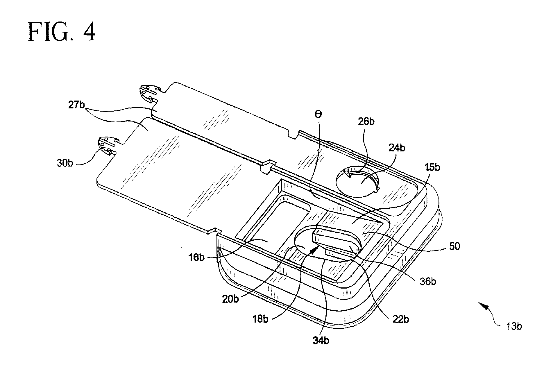
- Fig 4 is a side angle perspective view of the cap portion of a preferred assembly;
- Fig 5 is an enlarged top perspective view of the unwinder section of the cap of Fig 4;
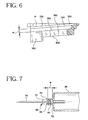
- Fig 6 is a horizontal sectional view of the unwinder section of Fig 5 taken along the line 6-6 thereof; and
- Fig 7 is a perspective view of a typical needle holder assembly as known in the art.
-
- While this invention is satisfied by embodiments in many different forms, there will herein be described in detail a preferred embodiment of the invention with the understanding that the present disclosure is to be considered as exemplary of the principles of the invention and is not intended to limit the invention to the embodiments illustrated and described. The scope of the invention will be measured by the appended claims and their equivalents.
- The following description is directed to the embodiment of the invention wherein the assembly is used to unwind a needle-hub unit threaded to a needle holder with the understanding that the principles of the invention may be used to unwind threaded components of any medical article to be discarded.
- Adverting now to the drawings, wherein like elements are given the same reference number followed by a lower case letter in the various illustrations thereof, Figs 1 and 2 illustrate a
sharps disposal assembly 10 including areceptacle 12 and acap 13.Cap 13 has a substantiallyflat top surface 14 which includes aplate section 15.Plate section 15 has a large port opening 16 and anunwinder opening 18, preferably V shaped, therethrough.Port opening 16 may be of any suitable geometrical configuration, but for the purpose of illustration, is shown in the preferred rectangular shape. Alternatively, the port and unwinder openings may be combined into a single, continuous opening.Unwinder opening 18 is recessed below the level ofplate 15 and extends from alarge end 20 to anarrow end 22. -
Cap 13 also has acircular opening 24 withinsert 26 therein expressly dimensioned to engage a SAFETY-GARD™ tube holder, as sold by Becton, Dickinson and Company.Opening 24 andinsert 26 are conventional features of prior art sharps disposal receptacles and are fully described in the aforementioned US Patent 5,092,462. -
Flaps 27 are affixed tocap 13 byintegral tabs 28 and haveintegral closure tabs 30 dimensioned for insertion intoslots 32 incap 13 to cover the openings. -
Plate section 15 ofcap 13 may preferably be slanted at an angle theta to the plane oftop surface 14 ofcap 13. This optional feature is illustrated in Fig 4 directed to the preferred embodiment of the assembly. Angle theta may be from 5-20°, preferably 10-15 °. - As shown in Fig 3, a
wall portion 36 ofunwinder 18a is vertically disposed downward fromplate 15a.Wall portion 36 is of particular width w which matches the length of the nose portion of a conventional tube holder, as shown in Fig 7.Wall portion 36 is integral with a horizontalunwinder shelf portion 38 which in turn is integral with avertical wall portion 40.Wall portion 40 may optionally have one or morevertical shoulders 42 projecting outwardly therefrom. - A preferred embodiment of the sharps disposal assembly is illustrated in Figs 4-6. Plate 15b is slanted at an angle theta relative to the plane of the top surface of
cap 13b whereby thenarrow end 22b of the unwinder is higher than thewide end 20b. - Unwinder 18b is part of a
recess 50 through plate 15b. A first segment ofrecess 50 is awall 52 vertically disposed downwardly from the plate.Wall 52 circumscribes ahorizontal platform 54 connected to a secondvertical wall portion 36c of width w. The second wall portion circumscribes ahorizontal shelf portion 38c which is connected to a thirdvertical wall portion 40c.Wall portion 40c may optionally have one or more shoulders (not shown in Figs 4-6) projecting vertically therefrom. - For purposes of illustration of the sharps disposal assembly of the invention, Fig 7 identifies key components of a conventional needle holder assembled to a needle hub unit.
Needle holder 60 hasflat bottom portion 62 andnose portion 64 havinginternal threads 66 for engaging mating threads on a needle-hub unit. The needle-hub unit includeshub 68 havingtop flange 70,ribs 72 andneedle 74. The distance frombottom portion 62 ofholder 60 to the end ofnose portion 64 is indicated as w. - In use of the preferred assembly of the invention, the technician, grasping
needle holder 60, insertsnose portion 64 with the attached needle-hub unit through thelarge end 20 of theunwinder opening 18 usingplatform 54 as an easy, error-proof visual and tactile guide for positioningbottom portion 62 ofholder 60 onto the platform. With this configuration, the needle-hub unit assumes the ideal perpendicular orientation toshelf 38 for advancement, regardless of whether or not the assembly in use includesslope 15. With the holder thus positioned, it is advanced into the unwinder, using tactile guidance only, the congruity of distance w for both the holder assembly andvertical wall portion 36 of the unwinder providing perfect engagement of theribs 70 ofhub 68 withunwinder wall portion 40, or with ashoulder 42 thereon. All guesswork and trial and error are eliminated resulting in error-free unwinding. - The assembly of the invention may be made of any suitable plastic, such as polyethylene, polypropylene and polyvinyl chloride. The lid with the unwinder elements is preferably made by conventional injection molding with integral construction wherein all the parts are continuous with no seams therebetween.
Claims (10)
- A sharps disposal assembly comprising:a) a substantially rigid storage receptacle;b) a cap for said receptacle comprising a flat top surface including a plate section, said plate section defining a plurality of openings into said receptacle;c) a first wall means perpendicularly disposed downward from said plate section and having a width matching the length of a nose portion of a tube holder;d) shelf means projecting horizontally from said first wall means; ande) a second wall means projecting perpendicularly downward from said shelf means.
- The assembly of Claim 1 further comprising a shoulder projecting from said second wall means.
- The assembly of Claim 1 wherein said plate section is slanted downwardly at an angle from the plane of said top surface.
- The assembly of Claim 1 wherein a first of said openings tapers from a wide end to a narrow end.
- The assembly of Claim 1 wherein a second of said openings is substantially rectangular and dimensioned to receive a large medical article.
- The assembly of Claim 1 wherein said flat top surface defines a third annular opening containing an insert to engage a needle holder.
- The assembly of Claim 1 wherein said cap further comprises a flap to cover one of said openings.
- A sharps disposal assembly comprising :a) a substantially rigid storage receptacle;b) a cap for said receptacle having a flat top surface and a plate section, said plate section being slanted downwardly at an angle from the plane of said top surface and defining a plurality of openings into said receptacle, a first of said openings being a V-shaped unwinder opening;c) a recess in said plate including said unwinder opening, said recess being bounded by a first vertical wall projecting downwardly from said plate section and circumscribing a horizontal platform, said platform connecting to a second vertical wall projecting downwardly from said platform and circumscribing a horizontal shelf, said shelf connecting to a third vertical wall, said second wall having a width matching the length of a nose portion of a tube holder; ande) flaps affixed to said cap to cover said openings.
- The assembly of Claim 8 wherein a second of said openings is substantially rectangular and dimensioned to receive a large medical article.
- The assembly of Claim 9 wherein said flat top surface defines a third annular opening containing an insert to engage a needle holder.
Applications Claiming Priority (2)
| Application Number | Priority Date | Filing Date | Title |
|---|---|---|---|
| US09/559,041 US6691867B1 (en) | 2000-04-27 | 2000-04-27 | Sharps disposal assembly having user-friendly unwinding feature |
| US559041 | 2000-04-27 |
Publications (2)
| Publication Number | Publication Date |
|---|---|
| EP1149600A1 true EP1149600A1 (en) | 2001-10-31 |
| EP1149600B1 EP1149600B1 (en) | 2005-07-20 |
Family
ID=24232039
Family Applications (1)
| Application Number | Title | Priority Date | Filing Date |
|---|---|---|---|
| EP01110285A Expired - Lifetime EP1149600B1 (en) | 2000-04-27 | 2001-04-26 | Sharps disposal assembly having user-friendly unwinding feature |
Country Status (4)
| Country | Link |
|---|---|
| US (2) | US6691867B1 (en) |
| EP (1) | EP1149600B1 (en) |
| JP (1) | JP2002058715A (en) |
| DE (1) | DE60111994T2 (en) |
Cited By (2)
| Publication number | Priority date | Publication date | Assignee | Title |
|---|---|---|---|---|
| WO2004060178A1 (en) * | 2002-12-16 | 2004-07-22 | Becton Dickinson And Company | Sharps disposal container |
| CN108888840A (en) * | 2018-05-17 | 2018-11-27 | 河南科技大学第附属医院 | A kind of medical sharps box device |
Families Citing this family (9)
| Publication number | Priority date | Publication date | Assignee | Title |
|---|---|---|---|---|
| US6691867B1 (en) * | 2000-04-27 | 2004-02-17 | Christopher R. Bickel | Sharps disposal assembly having user-friendly unwinding feature |
| US6712207B2 (en) * | 2001-08-21 | 2004-03-30 | Tyco Healthcare Group Lp | Apparatus and method for unwinding a needle portion |
| US8875881B2 (en) * | 2005-09-27 | 2014-11-04 | Covidien Ag | Method and apparatus for collecting sharps |
| US7789230B2 (en) * | 2005-09-27 | 2010-09-07 | Covidien Ag | Method and apparatus for collecting sharps |
| US8584850B2 (en) * | 2005-09-27 | 2013-11-19 | Covidien Ag | Apparatus for collecting sharps |
| JP2009029291A (en) * | 2007-07-27 | 2009-02-12 | Ricoh Co Ltd | Paper refilling/transfer assisting device |
| JP5373916B2 (en) * | 2008-09-18 | 2013-12-18 | ベクトン・ディキンソン・アンド・カンパニー | Medical injector with connected body parts |
| JP2012165894A (en) * | 2011-02-15 | 2012-09-06 | Epokku Chemical:Kk | Used injection needle recovery container |
| US10321968B2 (en) | 2015-10-23 | 2019-06-18 | Medline Industries, Inc. | Sharps container |
Citations (6)
| Publication number | Priority date | Publication date | Assignee | Title |
|---|---|---|---|---|
| US4375849A (en) | 1981-05-15 | 1983-03-08 | Sage Products, Inc. | Syringe needle removal and disposal device |
| US4466538A (en) | 1983-04-15 | 1984-08-21 | Biosafety Systems, Inc. | Hypodermic needle disposal system |
| US4875265A (en) * | 1987-12-14 | 1989-10-24 | Nissho Corporation | Injection needle-detaching device |
| US5092462A (en) | 1990-08-31 | 1992-03-03 | Medical Safety Products, Inc. | Disposal for disengaging and receiving needles |
| US5205409A (en) * | 1989-10-19 | 1993-04-27 | John Bruno | Needle removal/containment and transport apparatus for safe storage and disposal of hypodermic needles/syringe assemblies |
| US5415315A (en) | 1993-09-17 | 1995-05-16 | Devon Industries, Inc. | Closure lid to disposable container for holding and disposing of used medical sharps and other medical-surgical materials |
Family Cites Families (28)
| Publication number | Priority date | Publication date | Assignee | Title |
|---|---|---|---|---|
| JPS4924696B1 (en) * | 1970-02-27 | 1974-06-25 | ||
| CH591720B5 (en) * | 1975-03-18 | 1977-09-30 | Ebauches Sa | |
| USRE33143E (en) | 1984-11-20 | 1990-01-09 | Lin Tec Verpackungstechnik Gmbh | Tray for receiving foodstuffs and a process and apparatus for producing it |
| US4657139A (en) | 1985-09-30 | 1987-04-14 | Sage Products, Inc. | Closure for a syringe collection and disposal container |
| USD292037S (en) | 1985-10-04 | 1987-09-22 | Sage Products, Inc. | Waste receptacle |
| US4842138A (en) | 1986-03-10 | 1989-06-27 | Devon Industries, Inc. | Rigid disposable container for holding and dispensing of used medical sharps and other medical-surgical materials |
| CH664469GA3 (en) * | 1986-05-26 | 1988-03-15 | ||
| USD304109S (en) | 1986-10-16 | 1989-10-17 | Sage Products, Inc. | Disposal container for sharp articles or the like |
| US4779728A (en) | 1986-11-24 | 1988-10-25 | Sage Products, Inc. | Sharps disposal container |
| JPS6422358U (en) * | 1987-07-31 | 1989-02-06 | ||
| USD306509S (en) | 1987-08-28 | 1990-03-06 | Sage Products, Inc. | Disposal container for sharp articles or the like |
| JPH0193047A (en) * | 1987-10-01 | 1989-04-12 | Matsushita Electric Ind Co Ltd | Fluorescent lamp |
| USD307841S (en) | 1988-04-15 | 1990-05-15 | Sage Products, Inc. | Combined needle disposal container and glove dispenser |
| US4863057A (en) | 1988-04-29 | 1989-09-05 | Sage Products, Inc. | Dual locked container system |
| US4984686A (en) | 1989-01-17 | 1991-01-15 | Med-Safe Systems, Inc. | Sharps container closure and needle extractor assembly |
| US5183156A (en) * | 1989-10-19 | 1993-02-02 | John Bruno | Needle removal/containment and transport apparatus for safe storage and disposal of hypodermic needles/syringe assemblies |
| US5107990A (en) | 1990-03-14 | 1992-04-28 | Devon Industries, Inc. | Rigid closure lid to a disposable container for holding and disposing of used medical sharps and other medical-surgical materials |
| GB9021075D0 (en) | 1990-09-27 | 1990-11-07 | Frontier Plastics South Wales | Improvements relating to sharps disposal containers |
| US5273161A (en) * | 1991-05-31 | 1993-12-28 | Medical Safety Products, Inc. | Needle disposal system comprised of blood collection holder and companion biohazard receptacle |
| US5402887A (en) * | 1992-09-16 | 1995-04-04 | Med-Safe Systems, Inc. | Needle extractor for disposable containers |
| US5322164A (en) * | 1993-01-19 | 1994-06-21 | Sage Products, Inc. | Needle disposal container and disposal system |
| US5535913A (en) * | 1994-10-20 | 1996-07-16 | Fisher-Price, Inc. | Odorless container |
| JP3081992B2 (en) * | 1996-10-02 | 2000-08-28 | セイコーインスツルメンツ株式会社 | Wristwatch with calendar |
| JP3939073B2 (en) * | 2000-03-31 | 2007-06-27 | セイコーインスツル株式会社 | Clock with calendar mechanism |
| US6691867B1 (en) * | 2000-04-27 | 2004-02-17 | Christopher R. Bickel | Sharps disposal assembly having user-friendly unwinding feature |
| JP2002341056A (en) * | 2001-05-11 | 2002-11-27 | Seiko Instruments Inc | Jumper structural body and timepiece provided with it |
| JP2004170271A (en) * | 2002-11-20 | 2004-06-17 | Seiko Instruments Inc | Clock with calendar |
| JP2004170270A (en) * | 2002-11-20 | 2004-06-17 | Seiko Instruments Inc | Self-winding watch having adjusting apparatus |
-
2000
- 2000-04-27 US US09/559,041 patent/US6691867B1/en not_active Expired - Lifetime
-
2001
- 2001-04-26 DE DE60111994T patent/DE60111994T2/en not_active Expired - Fee Related
- 2001-04-26 EP EP01110285A patent/EP1149600B1/en not_active Expired - Lifetime
- 2001-04-27 JP JP2001133523A patent/JP2002058715A/en active Pending
-
2003
- 2003-11-18 US US10/716,013 patent/US20040134817A1/en not_active Abandoned
Patent Citations (6)
| Publication number | Priority date | Publication date | Assignee | Title |
|---|---|---|---|---|
| US4375849A (en) | 1981-05-15 | 1983-03-08 | Sage Products, Inc. | Syringe needle removal and disposal device |
| US4466538A (en) | 1983-04-15 | 1984-08-21 | Biosafety Systems, Inc. | Hypodermic needle disposal system |
| US4875265A (en) * | 1987-12-14 | 1989-10-24 | Nissho Corporation | Injection needle-detaching device |
| US5205409A (en) * | 1989-10-19 | 1993-04-27 | John Bruno | Needle removal/containment and transport apparatus for safe storage and disposal of hypodermic needles/syringe assemblies |
| US5092462A (en) | 1990-08-31 | 1992-03-03 | Medical Safety Products, Inc. | Disposal for disengaging and receiving needles |
| US5415315A (en) | 1993-09-17 | 1995-05-16 | Devon Industries, Inc. | Closure lid to disposable container for holding and disposing of used medical sharps and other medical-surgical materials |
Cited By (3)
| Publication number | Priority date | Publication date | Assignee | Title |
|---|---|---|---|---|
| WO2004060178A1 (en) * | 2002-12-16 | 2004-07-22 | Becton Dickinson And Company | Sharps disposal container |
| AU2003297130B2 (en) * | 2002-12-16 | 2009-07-02 | Becton, Dickinson And Company | Sharps disposal container |
| CN108888840A (en) * | 2018-05-17 | 2018-11-27 | 河南科技大学第附属医院 | A kind of medical sharps box device |
Also Published As
| Publication number | Publication date |
|---|---|
| EP1149600B1 (en) | 2005-07-20 |
| US20040134817A1 (en) | 2004-07-15 |
| US6691867B1 (en) | 2004-02-17 |
| JP2002058715A (en) | 2002-02-26 |
| DE60111994D1 (en) | 2005-08-25 |
| DE60111994T2 (en) | 2006-05-24 |
Similar Documents
| Publication | Publication Date | Title |
|---|---|---|
| US6253916B1 (en) | Sharps disposal assembly having improved unwinder | |
| US4989307A (en) | Apparatus for facilitating of the removal and disposal of medical needles | |
| US8684176B2 (en) | Apparatus and method for unwinding a needle portion | |
| US6247592B1 (en) | System for disposal of contaminated medical products | |
| CA2112759C (en) | Needle disposal container and disposal system | |
| US6691867B1 (en) | Sharps disposal assembly having user-friendly unwinding feature | |
| US4278225A (en) | Inclined vial holder | |
| US4375849A (en) | Syringe needle removal and disposal device | |
| CA2214447C (en) | Shielded needle assembly | |
| US6062001A (en) | Sharps disposal container | |
| US4875265A (en) | Injection needle-detaching device | |
| EP0867378A2 (en) | Assembly for collecting blood or other body fluids | |
| EP0225951A1 (en) | Disposable safety needle sheath | |
| US5117997A (en) | Disposal container and transport case for infectious and hazardous waste material | |
| JPH0321441B2 (en) | ||
| JPH01502164A (en) | A containment device for safely removing, storing, and handling hypodermic syringes or hypodermic needles. | |
| US4913309A (en) | Disposal container and transport case for infectious and hazardous waste material | |
| US5183156A (en) | Needle removal/containment and transport apparatus for safe storage and disposal of hypodermic needles/syringe assemblies | |
| US5810167A (en) | Infectious waste container for blood collection needles | |
| US20180361064A1 (en) | Venting Safety Closure | |
| US5857569A (en) | Twist unlock and downward push disengage needle unlocker system | |
| JPS62112531A (en) | Closure apparatus of blood sampling needle disposal system | |
| JPH0410820B2 (en) | ||
| GB2087360A (en) | Disposal Bin | |
| US4841818A (en) | Vial stopper removal device |
Legal Events
| Date | Code | Title | Description |
|---|---|---|---|
| PUAI | Public reference made under article 153(3) epc to a published international application that has entered the european phase |
Free format text: ORIGINAL CODE: 0009012 |
|
| AK | Designated contracting states |
Kind code of ref document: A1 Designated state(s): DE FR GB IT Kind code of ref document: A1 Designated state(s): AT BE CH CY DE DK ES FI FR GB GR IE IT LI LU MC NL PT SE TR |
|
| AX | Request for extension of the european patent |
Free format text: AL;LT;LV;MK;RO;SI |
|
| 17P | Request for examination filed |
Effective date: 20020307 |
|
| AKX | Designation fees paid |
Free format text: DE FR GB IT |
|
| 17Q | First examination report despatched |
Effective date: 20031229 |
|
| GRAP | Despatch of communication of intention to grant a patent |
Free format text: ORIGINAL CODE: EPIDOSNIGR1 |
|
| GRAS | Grant fee paid |
Free format text: ORIGINAL CODE: EPIDOSNIGR3 |
|
| GRAA | (expected) grant |
Free format text: ORIGINAL CODE: 0009210 |
|
| AK | Designated contracting states |
Kind code of ref document: B1 Designated state(s): DE FR GB IT |
|
| PG25 | Lapsed in a contracting state [announced via postgrant information from national office to epo] |
Ref country code: IT Free format text: LAPSE BECAUSE OF FAILURE TO SUBMIT A TRANSLATION OF THE DESCRIPTION OR TO PAY THE FEE WITHIN THE PRESCRIBED TIME-LIMIT;WARNING: LAPSES OF ITALIAN PATENTS WITH EFFECTIVE DATE BEFORE 2007 MAY HAVE OCCURRED AT ANY TIME BEFORE 2007. THE CORRECT EFFECTIVE DATE MAY BE DIFFERENT FROM THE ONE RECORDED. Effective date: 20050720 |
|
| REG | Reference to a national code |
Ref country code: GB Ref legal event code: FG4D |
|
| REF | Corresponds to: |
Ref document number: 60111994 Country of ref document: DE Date of ref document: 20050825 Kind code of ref document: P |
|
| ET | Fr: translation filed | ||
| PLBE | No opposition filed within time limit |
Free format text: ORIGINAL CODE: 0009261 |
|
| STAA | Information on the status of an ep patent application or granted ep patent |
Free format text: STATUS: NO OPPOSITION FILED WITHIN TIME LIMIT |
|
| 26N | No opposition filed |
Effective date: 20060421 |
|
| PGFP | Annual fee paid to national office [announced via postgrant information from national office to epo] |
Ref country code: DE Payment date: 20070531 Year of fee payment: 7 |
|
| PGFP | Annual fee paid to national office [announced via postgrant information from national office to epo] |
Ref country code: GB Payment date: 20070425 Year of fee payment: 7 |
|
| PGFP | Annual fee paid to national office [announced via postgrant information from national office to epo] |
Ref country code: FR Payment date: 20070417 Year of fee payment: 7 |
|
| GBPC | Gb: european patent ceased through non-payment of renewal fee |
Effective date: 20080426 |
|
| PG25 | Lapsed in a contracting state [announced via postgrant information from national office to epo] |
Ref country code: DE Free format text: LAPSE BECAUSE OF NON-PAYMENT OF DUE FEES Effective date: 20081101 |
|
| REG | Reference to a national code |
Ref country code: FR Ref legal event code: ST Effective date: 20081231 |
|
| PG25 | Lapsed in a contracting state [announced via postgrant information from national office to epo] |
Ref country code: FR Free format text: LAPSE BECAUSE OF NON-PAYMENT OF DUE FEES Effective date: 20080430 |
|
| PG25 | Lapsed in a contracting state [announced via postgrant information from national office to epo] |
Ref country code: GB Free format text: LAPSE BECAUSE OF NON-PAYMENT OF DUE FEES Effective date: 20080426 |