EP1152244A2 - Device for positioning objects - Google Patents
Device for positioning objects Download PDFInfo
- Publication number
- EP1152244A2 EP1152244A2 EP01108285A EP01108285A EP1152244A2 EP 1152244 A2 EP1152244 A2 EP 1152244A2 EP 01108285 A EP01108285 A EP 01108285A EP 01108285 A EP01108285 A EP 01108285A EP 1152244 A2 EP1152244 A2 EP 1152244A2
- Authority
- EP
- European Patent Office
- Prior art keywords
- insert
- sample
- optical sensor
- barcode
- sample tube
- Prior art date
- Legal status (The legal status is an assumption and is not a legal conclusion. Google has not performed a legal analysis and makes no representation as to the accuracy of the status listed.)
- Granted
Links
Images
Classifications
-
- G—PHYSICS
- G01—MEASURING; TESTING
- G01N—INVESTIGATING OR ANALYSING MATERIALS BY DETERMINING THEIR CHEMICAL OR PHYSICAL PROPERTIES
- G01N35/00—Automatic analysis not limited to methods or materials provided for in any single one of groups G01N1/00 - G01N33/00; Handling materials therefor
- G01N35/02—Automatic analysis not limited to methods or materials provided for in any single one of groups G01N1/00 - G01N33/00; Handling materials therefor using a plurality of sample containers moved by a conveyor system past one or more treatment or analysis stations
- G01N35/04—Details of the conveyor system
-
- G—PHYSICS
- G01—MEASURING; TESTING
- G01N—INVESTIGATING OR ANALYSING MATERIALS BY DETERMINING THEIR CHEMICAL OR PHYSICAL PROPERTIES
- G01N35/00—Automatic analysis not limited to methods or materials provided for in any single one of groups G01N1/00 - G01N33/00; Handling materials therefor
- G01N35/00584—Control arrangements for automatic analysers
- G01N35/00722—Communications; Identification
- G01N35/00732—Identification of carriers, materials or components in automatic analysers
- G01N2035/00742—Type of codes
- G01N2035/00752—Type of codes bar codes
-
- G—PHYSICS
- G01—MEASURING; TESTING
- G01N—INVESTIGATING OR ANALYSING MATERIALS BY DETERMINING THEIR CHEMICAL OR PHYSICAL PROPERTIES
- G01N35/00—Automatic analysis not limited to methods or materials provided for in any single one of groups G01N1/00 - G01N33/00; Handling materials therefor
- G01N35/02—Automatic analysis not limited to methods or materials provided for in any single one of groups G01N1/00 - G01N33/00; Handling materials therefor using a plurality of sample containers moved by a conveyor system past one or more treatment or analysis stations
- G01N35/04—Details of the conveyor system
- G01N2035/0474—Details of actuating means for conveyors or pipettes
- G01N2035/0491—Position sensing, encoding; closed-loop control
Landscapes
- Physics & Mathematics (AREA)
- Health & Medical Sciences (AREA)
- Life Sciences & Earth Sciences (AREA)
- Chemical & Material Sciences (AREA)
- Analytical Chemistry (AREA)
- Biochemistry (AREA)
- General Health & Medical Sciences (AREA)
- General Physics & Mathematics (AREA)
- Immunology (AREA)
- Pathology (AREA)
- Automatic Analysis And Handling Materials Therefor (AREA)
- Length Measuring Devices By Optical Means (AREA)
Abstract
Description
Die Erfindung betrifft eine Vorrichtung zur Positionierung von Objekten in einer Sollposition.The invention relates to a device for positioning objects in a target position.
Generell werden derartige Vorrichtungen bei Anlagen mit Transportsystemen eingesetzt, bei welchen Objekte in vorgegebene Sollpositionen für eine maschinelle oder manuelle Bearbeitung eingefahren werden müssen.Devices of this type are generally used in systems with transport systems used for which objects in predetermined target positions for a machine or manual processing must be run in.
Dabei besteht eine wesentliche Problematik darin, dass Objekte nicht nur in vorgegebene Sollpositionen möglichst genau positioniert werden müssen. Vielmehr müssen die Objekte dabei auch eindeutig identifizierbar sein, um Verwechslungen von Objekten zu vermeiden.A major problem here is that objects are not only in specified target positions must be positioned as precisely as possible. Rather, the objects must also be clearly identifiable in order to Avoid confusion of objects.
Ein Beispiel hierfür sind Blutanalysegeräte, mittels derer Analysen von Blutproben durchgeführt werden. Die Blutproben sind in einzelnen Probenröhrchen enthalten, welche nacheinander dem Blutanalysegerät zugeführt werden. Typischerweise wird mittels einer Nadel, die über den Verschluss eines Probenröhrchens in dessen Innenraum eingeführt wird, eine Probe entnommen, welche anschließend einer Analyse unterzogen wird.An example of this are blood analyzers, by means of which analyzes of blood samples be performed. The blood samples are in individual sample tubes included, which are fed to the blood analyzer one after the other. Typically by means of a needle, which is placed over the closure of a sample tube a sample is taken in the interior, which is then subjected to an analysis.
Derartige Blutanalysegeräte weisen einen hohen Durchsatz auf, so dass diesem eine große Menge an Probenröhrchen pro Zeiteinheit zugeführt wird. Bei der Durchführung der Analysen ist eine wesentliche Voraussetzung, dass die einzelnen Probenröhrchen eindeutig identifizierbar sind und die Analysen den jeweiligen Probenröhrchen zugeordnet werden können. Eine Verwechslung einzelner Proben könnte für den Patienten, dem die Blutproben entnommen wurden, eine Fehldiagnose bedeuten, die letztlich auch zu einer Gefährdung des Patienten führen könnte.Such blood analyzers have a high throughput, so this a large amount of sample tubes are supplied per unit time. In the Carrying out the analyzes is an essential requirement that the individual Sample tubes are clearly identifiable and the analyzes the can be assigned to the respective sample tube. A mix up individual samples could be taken for the patient from whom the blood samples were taken have been misdiagnosed, which ultimately also poses a risk of the patient.
Um derartige Risiken auszuschließen, werden typischerweise die Probenröhrchen mit eindeutigen Kennungen gekennzeichnet, die vom Bedienpersonal bei der Durchführung der Blutanalyse identifiziert werden können. Damit können zwar Verwechslungen einzelner Probenröhrchen ausgeschlossen werden, jedoch muss die Durchführung der Blutanalysen und insbesondere der Transport der Probenröhrchen zu dem Blutanalysegerät vom Bedienpersonal überwacht werden. Abgesehen davon, dass durch menschliches Versagen nach wie vor eine fehlerhafte Zuordnung von durchgeführten Analysen zu den zugehörigen Proben in Probenröhrchen möglich ist, ist bei derartigen Anlagen ein hoher Personaleinsatz erforderlich.To avoid such risks, the sample tubes are typically used identified with unique identifiers by the operating personnel performing the blood analysis can be identified. So that can confusion of individual sample tubes can be excluded, however must carry out the blood tests and especially the transport the operator monitors the sample tube to the blood analyzer become. Aside from the fact that human error continues an incorrect assignment of performed analyzes to the associated ones Samples in sample tubes are possible, is a high one with such systems Personnel deployment required.
Der Erfindung liegt die Aufgabe zugrunde eine Vorrichtung bereitzustellen, welche eine exakte, automatisierte Positionierung von Objekten gewährleistet, wobei gleichzeitig eine eindeutige Identifikation und Verfolgung der Objekte gewährleistet ist.The invention has for its object to provide a device which ensures an exact, automated positioning of objects, at the same time a clear identification and tracking of the objects is guaranteed.
Zur Lösung dieser Aufgabe sind die Merkmale des Anspruchs 1 vorgesehen.
Vorteilhafte Ausführungsformen und zweckmäßige Weiterbildungen der Erfindung
sind in den Unteransprüchen beschrieben.The features of
Die erfindungsgemäße Vorrichtung zur Positionierung von Objekten in einer Sollposition weist einen optischen Sensor mit einem Sendelichtstrahlen emittierenden Sender, einem Empfangslichtstrahlen empfangenden Empfänger und einer Auswerteeinheit auf. Mittels der Sendelichtstrahlen wird die Sollposition abgetastet. Die Vorrichtung weist wenigstens eine Aufnahmevorrichtung auf, in welcher eine vorgegebene Anzahl von Objekten in vorgegebenen Einschubpositionen gelagert ist. Jede Einschubposition ist durch eine Positions-Marke gekennzeichnet. Die Vorrichtung weist weiterhin ein Transportsystem auf, mittels dessen die Aufnahmevorrichtung relativ zum optischen Sensor bewegt wird. Die Aufnahmevorrichtung wird angehalten, sobald die Positions-Marke einer Einschubposition für ein vorgegebenes Objekt von dem optischen Sensor erfasst wird, wobei das jeweilige Objekt anhand von Objekt-Marken mittels des Sensors identifizierbar ist.The device according to the invention for positioning objects in a Target position has an optical sensor with a light beam emitting Transmitter, a receiver and receiving light beams an evaluation unit. The target position is determined by means of the transmitted light beams scanned. The device has at least one receiving device, in which a predetermined number of objects in predetermined insertion positions is stored. Each insertion position is marked by a position mark characterized. The device also has a transport system, by means of which the receiving device moves relative to the optical sensor becomes. The cradle is stopped once the position mark an insertion position for a given object from the optical sensor is recorded, the respective object using object marks by means of of the sensor is identifiable.
Der wesentliche Vorteil der erfindungsgemäßen Vorrichtung besteht darin, dass mittels des optischen Sensors nicht nur eine zielgenaue Positionierung der Objekte in einer Sollposition ermöglicht wird. Zudem wird mittels des optischen Sensors eine eindeutige Identifizierung der Objekte gewährleistet, wobei gleichzeitig eine eindeutige Zuordnung der Objekte zu den Einschubpositionen in der Aufnahmevorrichtung gewährleistet ist.The main advantage of the device according to the invention is that by means of the optical sensor not only a precise positioning of the objects is made possible in a target position. In addition, by means of the optical Sensor ensures a clear identification of the objects, whereby at the same time a clear assignment of the objects to the insertion positions is guaranteed in the receiving device.
Durch die Identifizierung der Objekte ist eine Verwechslung verschiedener Objekte mit großer Sicherheit ausgeschlossen. Dabei ist zudem durch die eindeutige Zuordnung der Objekte zu den Einschubpositionen der Aufnahmevorrichtungen eine genaue Lokalisierung und Verfolgbarkeit der einzelnen Objekte innerhalb des Transportsystems gegeben.By identifying the objects, a confusion is different Objects excluded with great certainty. It is also by the clear Assignment of the objects to the insertion positions of the holding devices precise localization and traceability of the individual objects given within the transport system.
In einer besonders vorteilhaften Ausführungsform der Erfindung ist die Vorrichtung Bestandteil einer Blutanalysevorrichtung. Die Blutanalysevorrichtung weist ein Blutanalysegerät auf. Ein Bestandteil des Blutanalysegeräts ist eine Probenentnahmevorrichtung mit einer Nadel. Die Objekte sind von Probenröhrchen gebildet, die Blutproben enthalten und mit einem Verschluss verschlossen sind. Zur Entnahme von Proben aus dem Probenröhrchen wird die Nadel über den Verschluss in das Innere des jeweiligen Probenröhrchens eingeführt.In a particularly advantageous embodiment of the invention, the device Part of a blood analysis device. The blood analyzer has a blood analyzer. One component of the blood analyzer is one Sampling device with a needle. The objects are from sample tubes formed, which contain blood samples and closed with a closure are. To take samples from the sample tube, the Insert the needle into the interior of the respective sample tube via the cap.
Erfindungsgemäß erfolgt die Zufuhr der Probenröhrchen zu der Nadel automatisiert, wobei die Probenröhrchen in Aufnahmevorrichtungen bildenden Probenhaltern einzeln nacheinander der Probenentnahmevorrichtung zugeführt werden. Die Probenröhrchen sind dabei in Einschüben der Probenhalter gelagert.According to the invention, the sample tubes are automatically supplied to the needle, the sample tubes in sample holders forming receptacles individually supplied to the sampling device in succession become. The sample tubes are stored in slots in the sample holder.
An diesen Einschüben ist jeweils eine Positions-Marke angeordnet, die aus einem Positions-Barcode und zwei Referenz-Linienelementen besteht. In dem Positions-Barcode ist die Nummer des Einschubs und damit dessen Lage innerhalb des Transportsystems kodiert. An den Probenröhrchen ist zudem jeweils eine als Objekt-Barcode ausgebildete Objekt-Marke angeordnet.A position mark is arranged on each of these inserts, which consists of a position barcode and two reference line elements. By doing Position barcode is the number of the slot and thus its location within of the transport system. On each of the sample tubes is also arranged an object mark designed as an object barcode.
Die Referenz-Linienelemente bilden eine Zielmarke, welche zur Positionierung eines Einschubs in die Sollposition, in welcher die Nadel angeordnet ist, dient. Bei Einfahren in die Sollposition wird zweckmäßigerweise der Abtastbereich des optischen Sensors so gewählt, dass allein die Positions-Marken an den Einschüben, nicht jedoch die Objekt-Marken erfasst werden.The reference line elements form a target, which is used for positioning an insert into the desired position in which the needle is arranged. When entering the target position, the scanning range is expediently the optical sensor so that only the position marks on the inserts, however, the object marks are not recorded.
Sobald die Positionierung eines Einschubs in der Sollposition abgeschlossen ist, wird in der Vorrichtung anhand der Erfassung des Positions-Barcodes die Position des Einschubs ermittelt. Dann wird der Abtastbereich des optischen Sensors erweitert, so dass auch der Objekt-Barcode erfasst wird. Dabei erfolgt nicht nur eine eindeutige Identifizierung des Probenröhrchens und dessen Inhalts, sondern auch eine Zuordnung zum jeweiligen Positions-Barcode, so dass auch eine eindeutige Lokalisierung des Probenröhrchens innerhalb des Transportsystems gewährleistet ist.As soon as the positioning of a slide in the target position is completed is in the device based on the detection of the position barcode Position of the insert determined. Then the scanning area of the optical Sensor expanded so that the object barcode is also captured. This is done not only clear identification of the sample tube and its contents, but also an assignment to the respective position barcode, so that also a clear location of the sample tube within the transport system is guaranteed.
Bei in der Sollposition liegendem Einschub wird die dort angeordnete Nadel der Probenentnahmevorrichtung in das entsprechende Probenröhrchen eingeführt, wonach aus dem Probenröhrchen eine Probe zur Durchführung einer Analyse entnommen wird. Die Analyseergebnisse werden zusammen mit den Informationen des zugeordneten Positions-Barcodes und Objekt-Barcodes abgespeichert, so dass das Analysenergebnis eindeutig zugeordnet werden kann. When the insert is in the desired position, the needle located there becomes the sampling device is inserted into the corresponding sample tube, after which a sample from the sample tube for performing an analysis is removed. The analysis results are together with the Information of the assigned position barcode and object barcode is saved, so that the analysis result can be clearly assigned.
Der Transport der Probenröhrchen zur Probenentnahmevorrichtung sowie die Entnahme einer Probe aus dem Probenröhrchen erfolgt somit automatisiert und ohne jeglichen Personaleinsatz.The transport of the sample tubes to the sampling device and the A sample is thus taken automatically from the sample tube without any human resources.
Die Erfindung wird im nachstehenden anhand der Zeichnungen erläutert. Es zeigen:
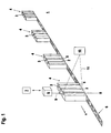
- Figur 1:
- Schematische Darstellung eines Ausführungsbeispiels der erfindungsgemäßen Vorrichtung mit auf einem Transportsystem geförderten, Aufnahmevorrichtungen bildenden Probenhaltern und einem optischen Sensor zur Positionierung von in Einschüben der Probenhalter gelagerten, Objekte bildenden Probenröhrchen in einer Sollposition.
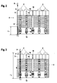
- Figur 2:
- Seitenansicht eines Probenhalters gemäß
Figur 1 mit in Einschüben gelagerten, außerhalb der Sollposition liegenden Probenröhrchen. - Figur 3:
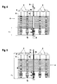
- Probenhalter gemäß
Figur 2 mit einem ein Probenröhrchen enthaltenden, in der Sollposition liegenden Einschub. - Figur 4:
- Probenhalter gemäß
Figur 2 mit einem leeren, außerhalb der Sollposition liegenden Einschub. - Figur 5:
- Probenhalter gemäß
Figur 2 mit einem leeren, innerhalb der Sollposition liegenden Einschub.
- Figure 1:
- Schematic representation of an embodiment of the device according to the invention with sample holders, which are conveyed on a transport system and form receiving devices, and an optical sensor for positioning sample tubes, which are stored in inserts of the sample holders, in a desired position.
- Figure 2:
- Side view of a sample holder according to FIG. 1 with sample tubes stored in inserts and lying outside the desired position.
- Figure 3:
- Sample holder according to FIG. 2 with an insert containing a sample tube and lying in the desired position.
- Figure 4:
- Sample holder according to Figure 2 with an empty, lying outside of the target position.
- Figure 5:
- Sample holder according to Figure 2 with an empty, lying within the target position.
Figur 1 zeigt schematisch ein Ausführungsbeispiel der erfindungsgemäßen Vorrichtung zur Positionierung von Objekten in einer Sollposition.Figure 1 shows schematically an embodiment of the invention Device for positioning objects in a target position.
Die Vorrichtung ist im vorliegenden Fall Bestandteil einer Blutanalysevorrichtung
1. Die Objekte sind von Probenröhrchen 2 gebildet, die vorzugsweise
Blutproben enthalten und an ihrer Oberseite jeweils mit einem Verschluss 3 in
Form eines Pfropfens verschlossen sind. Die Probenröhrchen 2 sind in mehreren
Probenhaltern 4 gelagert, welche Aufnahmevorrichtungen für die Objekte
bilden. Die Probenhalter 4 sind jeweils identisch ausgebildet und weisen jeweils
eine vorgegebene Anzahl von Einschüben 5 auf. Die Einschübe 5 sind
identisch ausgebildet und dienen jeweils zur Aufnahme eines Probenröhrchens
2.In the present case, the device is part of a
Die Probenhalter 4 werden mittels eines Transportsystems 6 in einer Förderrichtung
v bewegt und einem Blutanalysegerät 7 zugeführt. Das Blutanalysegerät
7 bildet das Kernstück der Blutanalysevorrichtung 1 und dient zur Durchführung
von Analysen von Blutproben.The
Das Transportsystem 6 ist von einem Fördersystem gebildet, in welchem die
Probenhalter 4 in vorgegebenen Abständen hintereinander angeordnet sind. Die
Probenröhrchen 2 stehen senkrecht im jeweiligen Probenhalter 4. Die Probenröhrchen
2 sind mit vertikal verlaufenden Längsachsen in den Probenhaltern 4
angeordnet, so dass die Verschlüsse an den Oberseiten der Probenröhrchen 2
frei zugänglich sind.The
Die auf dem Fördersystem transportierten Probenhalter 4 werden nacheinander
einer mit dem Blutanalysegerät 7 zusammenarbeitenden Probenentnahmevorrichtung
8 zugeführt. Vorzugsweise bildet die Probenentnahmevorrichtung 8
einen Teil des Blutanalysegeräts 7.The
Die Probenentnahmevorrichtung 8 weist eine automatisch gesteuerte Nadel 9
zur Entnahme von Proben aus den Probenröhrchen 2 auf. Zur Entnahme einer
Probe wird das entsprechende Probenröhrchen 2 in einer Sollposition direkt
unterhalb der Nadel 9 positioniert. Die Sollposition ist dabei von einer vertikal
verlaufenden Geraden S gebildet, die quer zur Förderrichtung v des Fördersystems
verläuft. Dabei verläuft die Längsachse der Nadel 9 längs dieser Geraden
S.The sampling device 8 has an automatically controlled
Sobald ein vorgegebenes Probenröhrchen 2 in der Sollposition liegt, wird das
Fördersystem angehalten und die Nadel 9 durch den Verschluss 3 in das Innere
des Probenröhrchens 2 zur Entnahme einer Probe eingeführt.As soon as a given
Die Vorrichtung zur Positionierung der Probenröhrchen 2 in die Sollposition
umfasst im Wesentlichen einen optischen Sensor 10 sowie eine nicht dargestellte
Steuereinheit zur Ansteuerung des optischen Sensors 10 und der Probenentnahmevorrichtung
8.The device for positioning the
Der optische Sensor 10 ist als Barcodelesegerät ausgebildet. Dieser weist im
Wesentlichen einen Sendelichtstrahlen 11 emittierenden Sender, einen Empfangslichtstrahlen
empfangenden Empfänger, eine Ablenkeinheit sowie eine
Auswerteeinheit auf.The
Die über die Ablenkeinheit geführten Sendelichtstrahlen 11 tasten periodisch
einen Abtastbereich ab Mit dem Barcodelesegerät werden innerhalb des Abtastbereichs
liegende, Kontrastmuster aufweisende Marken erfasst. Dabei wird
den an den Marken als Empfangslichtstrahlen reflektierten Sendelichtstrahlen
11 entsprechend dem Kontrastmuster der Marke eine Amplitudenmodulation
aufgeprägt, welche zur Erfassung der Marke in der Auswerteeinheit ausgewertet
wird.The transmitted
Der von den Sendelichtstrahlen 11 erfasste Abtastbereich verläuft längs der die
Sollposition bildenden Geraden S. Prinzipiell kann mit den Sendelichtstrahlen
11 des Barcodelesegeräts ein linienförmiger Abtastbereich erfasst werden. Im
vorliegenden Fall wird mittels der Sendelichtstrahlen 11 ein flächiges Raster
abgetastet, um auf dem Probenhalter 4 und/oder am Probenröhrchen 2 angeordnete
Marken zu erfassen. Das Raster bildet ein rechteckförmiges Flächenelement,
wobei die Größe dieses Flächenelements in der Ebene des abgetasteten
Probenhalters 4 an die Größen der zu erfassenden Marken angepasst ist.The scanning area captured by the transmitted
Die von den Sendelichtstrahlen 11 überstrichenen Raster und die zu erfassenden
Marken sind in den Figuren 2 - 5 dargestellt.The grids swept by the transmitted
In den Figuren 2 - 5 ist jeweils die dem optischen Sensor 10 zugewandte und
von den Sendelichtstrahlen 11 abgetastete Seitenfläche eines Probenhalters 4
dargestellt.FIGS. 2-5 each show the one facing the
Der Probenhalter 4 weist eine im Wesentlichen quaderförmige Kontur auf, wobei
die dem optischen Sensor 10 zugewandte Seitenfläche eine im Wesentlichen
ebene, rechteckförmige Fläche bildet. Der in den Figuren 2 - 5 dargestellte
Probenhalter 4 weist fünf identische, in vertikaler Richtung verlaufende
Einschübe 5 auf. Die Einschübe 5 sind äquidistant angeordnet und münden an
der Oberseite des Probenhalters 4 aus. Die in den Einschüben 5 gelagerten, im
Wesentlichen zylindrischen Probenröhrchen 2 stehen mit ihren Verschlüssen
über die oberen Ränder der Einschübe 5 hervor.The
Zur Positionierung eines Einschubes 5 in die Sollposition sind in den Bereichen
der Unterseiten der Einschübe 5 auf der Seitenfläche des Probenhalters 4 Positions-Marken
aufgebracht. Jede einem Einschub 5 zugeordnete Positions-Marke
verläuft in Richtung der Längsachse dieses Einschubs 5.To position an
Jede Positions-Marke weist einen Positions-Barcode 12 auf. In diesem Positions-Barcode
12 ist die Nummer des jeweiligen Einschubs 5 des Probenhalters
4 kodiert. Dabei sind die Einschübe 5 sämtlicher Probenhalter 4 mit fortlaufenden
Nummern bezeichnet. Durch die jeweilige Nummer ist somit die Position
eines jeden Einschubs 5 innerhalb der Gesamtheit aller Probenhalter 4 des
Transportsystems 6 eindeutig gekennzeichnet. Zweckmäßigerweise ist die
Nummer eines Einschubs 5 nicht nur im jeweiligen Positions-Barcode 12 am
Einschub 5 angebracht, sondern auch im Klartext in Form einer Ziffernfolge.
Die Positions-Barcodes 12 bestehen aus einer Folge von hellen und dunklen
Linienelementen, deren Längsachsen quer zur Längsachse des jeweiligen Einschubs
5 und quer zur Abtastrichtung der Sendelichtstrahlen 11 des optischen
Sensors 10 verlaufen.Each position mark has a
Jeder Positions-Barcode 12 weist an seinen längsseitigen Enden eine Ruhezone
vorgegebener Breite auf. In jeder dieser Ruhezonen liegt ein Referenz-Linienelement
13. Die Längsachsen der Referenz-Linienelemente 13 verlaufen
parallel zu den Längsachsen der Linienelemente des jeweiligen Positions-Barcodes
12.Each
Die eine Zielmarke bildenden Referenz-Linienelemente 13 sind Bestandteil
einer Positions-Marke und dienen zur Positionierung des jeweiligen Einschubs
5 in der Sollposition.The
Auf den Außenseiten der Probenröhrchen 2 ist als Objekt-Marke jeweils ein
Objekt-Barcode 14 aufgebracht, in welchem der Inhalt eines Probenröhrchens 2
kodiert ist.On the outside of the
Jeder Einschub 5 weist eine Öffnung 15 auf, welche an der dem optischen Sensor
10 zugewandten Seitenfläche des Probenhalters 4 ausmündet. Die Öffnung
15 ist an die Größe eines Objekt-Barcodes 14 angepasst, so dass dieser durch
die Öffnung 15 vollständig sichtbar ist und vom optischen Sensor 10 erfasst
wird, falls das Probenröhrchen 2 in dem Einschub 5 liegt. Dabei verläuft die
Längsachse der Öffnung 15 in Längsrichtung des Einschubs 5.Each
Weiterhin ist an der der Öffnung 15 gegenüberliegenden Innenseite eines jeden
Einschubs 5 ein Referenz-Barcode 16 zur Überprüfung der Belegung des Einschubs
5 mit einem Probenröhrchen 2 vorgesehen. Der Referenz-Barcode 16 ist
bei leerem Einschub 5 durch die Öffnung 15 sichtbar und kann so von dem
optischen Sensor 10 abgetastet werden. Ist jedoch ein Probenröhrchen 2 im
Eischub gelagert, verdeckt das Probenröhrchen 2 den Referenz-Barcode 16, so
dass dieser vom optischen Sensor 10 nicht abgetastet werden kann.Furthermore, on the inside of each opening opposite the
Die Positions-Marken, die Objekt-Marken und die Referenz-Marken werden
von dem optischen Sensor 10 abgetastet, wobei der Abtastbereich des Sensors
10 von einem flächigen Raster gebildet ist, dessen Längsachse entlang der die
Sollposition gebildeten Geraden S verläuft, entlang derer auch die Nadel 9 der
Probenentnahmevorrichtung 8 verläuft.The position marks, the object marks and the reference marks become
scanned by the
Die Breite des Rasters ist konstant und ist in den Figuren 2 - 5 mit Δd bezeichnet.
Der optische Sensor 10 ist zwischen zwei Betriebsmodi umschaltbar. In
einem ersten Betreibsmodus wird zur Positionierung eines Einschubes 5 in der
Sollposition von den Sendelichtstrahlen 11 des optischen Sensors 10 ein Raster
der Breite Δd und der Länge Δx abgetastet. Die Länge des Rasters ist derart an
die Größe der Positions-Marken angepasst, dass vom optischen Sensor 10 die
Positions-Marken vollständig erfasst werden, die Objekt-Marken und die Referenz-Barcodes
16 jedoch außerhalb des Rasters liegen.The width of the grid is constant and is designated Δd in FIGS. 2-5.
The
In einem zweiten Betriebsmodus wird bei einem in der Sollposition liegenden
Einschub 5 vom optischen Sensor 10 ein Raster der Breite Δd und der Länge
Δy abgetastet. Die Länge Δy des Rasters erstreckt sich dabei über die gesamte
Höhe des Probenhalters 4, so dass im zweiten Betriebsmodus sowohl die Positions-Marken
als auch die Objekt-Marken und die Referenz-Barcodes 16 erfasst
werden.In a second operating mode, one is in the
Die Umschaltung vom ersten in den zweiten Betriebsmodus erfolgt durch ein
Triggersignal, welches intern in der Auswerteeinheit generiert wird, sobald ein
Einschub 5 in der Sollposition liegend vom optischen Sensor 10 erfasst wird. The switch from the first to the second operating mode is carried out by a
Trigger signal, which is generated internally in the evaluation unit, as soon as a
Die Umschaltung vom zweiten in den ersten Betriebsmodus erfolgt durch eine
externes Triggersignal, welches vorzugsweise in der Steuereinheit generiert
wird und in den optischen Sensor 10 eingelesen wird.The switch from the second to the first operating mode is carried out by a
external trigger signal, which is preferably generated in the control unit
is and is read into the
Die Funktionsweise der erfindungsgemäßen Vorrichtung wird im Folgenden anhand der Figuren 2 - 5 erläutert.The mode of operation of the device according to the invention is described below explained with reference to Figures 2-5.
Bei der Anordnung gemäß Figur 2 wird der Probenhalter 4 entlang der Förderrichtung
v relativ zum optischen Sensor 10 bewegt. Dabei liegt keiner der Einschübe
5 in der Sollposition. Der optische Sensor 10 befindet sich im ersten
Betriebsmodus, so dass ein Raster der Länge Δx zur Erfassung der Positions-Marken
abgetastet wird.In the arrangement according to Figure 2, the
Die Positionierung in die Sollposition ist dann abgeschlossen, wenn das Raster
vollständig auf den die Zielmarke bildenden Referenz-Linienelementen 13 einer
Positions-Marke liegt.The positioning in the target position is then complete when the grid
completely on the
Die Längen der identisch ausgebildeten Referenz-Linienelemente 13 sind dabei
etwas größer als die Breite Δd des Rasters und kleiner als die Durchmesser der
Verschlüsse ausgebildet. Wird bei der Abtastung einer Positions-Marke festgestellt,
dass das gesamte Raster auf den Referenzlinien liegt, ist sichergestellt,
dass der jeweilige Einschub 5 mit einer hinreichenden Genauigkeit in der Sollposition
liegt, so dass in jedem Fall die Nadel 9 der Probenentnahmevorrichtung
8 oberhalb des Verschlusses 3 liegt und in diesen eingestochen wird. Insbesondere
ist durch die Dimensionierung des Rasters und der Referenz-Linienelemente
13 gewährleistet, dass ein Einschub 5 gegenüber der die Sollposition
bildenden Geraden S nicht verkippt ist, was ein Einführen der Nadel 9
in den Verschluss 3 behindern würde.The lengths of the identically designed
Nachdem ein Einschub 5 in der Sollposition positioniert wurde und der Positions-Barcode
12 des jeweiligen Einschubes 5 erfasst wurde, wird das Fördersystem
angehalten und der optische Sensor 10 in den zweiten Betriebsmodus
umgeschaltet. Damit wird der Abtastbereich auf das Raster der Länge Δy vergrößert,
so dass auch der Objekt-Barcode 14 des Probenröhrchens 2, welches in
dem in der Sollposition liegenden Einschub 5 gelagert ist, erfasst wird. Diese
Situation ist in Figur 3 dargestellt.After an
Nachdem sowohl die Positions-Marke des Einschubs 5 in der Sollposition und
die Objekt-Marke des entsprechenden Probenröhrchens 2 erfasst wurde, wird
über die Steuereinheit die Nadel 9 der Probenentnahmevorrichtung 8 über den
Verschluss 3 in das Innere des Probenröhrchens 2 eingeführt. Die dabei entnommene
Probe wird in dem Blutanalysegerät 7 analysiert. Das Analyseergebnis
wird zusammen mit dem ermittelten Positions-Barcode 12 und dem ermittelten
Objekt-Barcode 14 abgespeichert, so dass eine eindeutige Zuordnung des
Analyseergebnisses zu dem Probenröhrchen 2 und dessen Anordnung innerhalb
der Einschübe 5 der Probenhalter 4 gewährleistet ist.After both the position mark of the
Sobald diese Vorgänge abgeschlossen sind, wird in der Steuereinheit das Triggersignal
zur Umschaltung in den ersten Betriebsmodus generiert. Gleichzeitig
wird über die Steuereinheit das Fördersystem wieder in Bewegung gesetzt. Danach
wird der Probenhalter 4 weiter gefördert, bis der nächste Einschub 5 in
der Sollposition positioniert ist. Auf diese Weise werden sämtliche Einschübe
5 der Probenhalter 4 nacheinander in der Sollposition positioniert.As soon as these processes have been completed, the trigger signal is generated in the control unit
generated to switch to the first operating mode. At the same time
the conveyor system is set in motion again via the control unit. After that
the
Figur 4 zeigt die Positionierung eines leeren Einschubes 5 in der Sollposition.
Die Positionierung ist dabei noch nicht abgeschlossen, da das Raster des optischen
Sensors 10 noch nicht vollständig auf den Referenz-Linienelementen 13
dieses Einschubes 5 liegt.Figure 4 shows the positioning of an
Figur 5 zeigt diesen Einschub 5 in der Sollposition, wobei bereits die Umschaltung
in den zweiten Betriebsmodus nach Erfassung des Positions-Barcodes
12 an diesem Einschub 5 erfolgt ist. Da dieser Einschub 5 leer ist,
wird kein Objekt-Barcode 14 eines Probenröhrchens 2, sondern der Referenz-Barcode
16 an diesem Einschub 5 erfasst. Dadurch wird in der Auswerteeinheit
des Sensors 10 festgestellt, dass der Einschub 5 leer ist. Vorzugsweise wird
dann in der Auswerteeinheit eine Warn- oder Fehlermeldung generiert, welche
dem Bedienpersonal die Nichtbelegung des Einschubes 5 anzeigt. Aufgrund
der Warn- oder Fehlermeldung wird über die Steuereinheit auch die Probenentnahmevorrichtung
8 deaktiviert. Dadurch bleibt die Nadel 9 in ihrer Ruhestellung,
um Beschädigungen oder Fehlfunktionen zu vermeiden. Figure 5 shows this
- (1)(1)
- BlutanalysevorrichtungBlood analyzer
- (2)(2)
- ProbenröhrchenSample tube
- (3)(3)
- VerschlussClasp
- (4)(4)
- ProbenhalterSample holder
- (5)(5)
- EinschübeInserts
- (6)(6)
- TransportsystemTransport system
- (7)(7)
- BlutanalysegerätBlood analyzer
- (8)(8th)
- ProbenentnahmevorrichtungSampling device
- (9)(9)
- Nadelneedle
- (10)(10)
- Optischer SensorOptical sensor
- (11)(11)
- SendelichtstrahlenTransmitted light beams
- (12)(12)
- Positions-BarcodePosition barcode
- (13)(13)
- Referenz-LinienelementeReference line elements
- (14)(14)
- Objekt-BarcodeObject barcode
- (15)(15)
- Öffnungopening
- (16)(16)
- Referenz-BarcodeReference barcode
Claims (25)
Applications Claiming Priority (2)
| Application Number | Priority Date | Filing Date | Title |
|---|---|---|---|
| DE10017718 | 2000-04-11 | ||
| DE10017718 | 2000-04-11 |
Publications (3)
| Publication Number | Publication Date |
|---|---|
| EP1152244A2 true EP1152244A2 (en) | 2001-11-07 |
| EP1152244A3 EP1152244A3 (en) | 2004-01-14 |
| EP1152244B1 EP1152244B1 (en) | 2006-08-16 |
Family
ID=7638191
Family Applications (1)
| Application Number | Title | Priority Date | Filing Date |
|---|---|---|---|
| EP01108285A Expired - Lifetime EP1152244B1 (en) | 2000-04-11 | 2001-04-02 | Device for positioning objects |
Country Status (3)
| Country | Link |
|---|---|
| US (1) | US6465770B2 (en) |
| EP (1) | EP1152244B1 (en) |
| DE (1) | DE50110732D1 (en) |
Families Citing this family (16)
| Publication number | Priority date | Publication date | Assignee | Title |
|---|---|---|---|---|
| US6870503B2 (en) | 2002-11-19 | 2005-03-22 | Farrokh Mohamadi | Beam-forming antenna system |
| CN101907630B (en) * | 2004-04-07 | 2012-03-07 | 泰肯贸易股份公司 | Device and method for identifying, locating and tracking objects on laboratory equipment |
| US7278328B2 (en) * | 2004-09-03 | 2007-10-09 | Protedyne Corporation | Method and apparatus for handling sample holders |
| US8763892B2 (en) | 2007-12-31 | 2014-07-01 | Oridon Medical 1987 Ltd. | Tube verifier |
| EP4336403A2 (en) | 2015-10-23 | 2024-03-13 | Gen-Probe Incorporated | Systems and methods for reading machine-readable marks on racks and receptacles |
| USD782695S1 (en) | 2015-12-18 | 2017-03-28 | Abbott Laboratories | Slide carrier |
| USD812244S1 (en) | 2015-12-18 | 2018-03-06 | Abbott Laboratories | Tube rack |
| USD782064S1 (en) | 2015-12-18 | 2017-03-21 | Abbott Laboratories | Tube rack |
| USD802787S1 (en) | 2015-12-18 | 2017-11-14 | Abbott Laboratories | Slide carrier |
| USD799057S1 (en) | 2015-12-18 | 2017-10-03 | Abbott Laboratories | Slide rack |
| USD799055S1 (en) | 2015-12-18 | 2017-10-03 | Abbott Laboratories | Smear tape cartridge |
| USD811616S1 (en) | 2015-12-18 | 2018-02-27 | Abbott Laboratories | Tube rack |
| USD793473S1 (en) | 2015-12-18 | 2017-08-01 | Abbott Laboratories | Print tape cartridge |
| USD799058S1 (en) | 2016-02-18 | 2017-10-03 | Abbott Laboratories | Slide caddy |
| US10598637B2 (en) * | 2017-07-18 | 2020-03-24 | Perkinelmer Health Sciences, Inc. | Automated thermal desorption systems configured to determine sample tube orientation and/or cap presence, and related methods |
| US10816516B2 (en) | 2018-03-28 | 2020-10-27 | Perkinelmer Health Sciences, Inc. | Autosamplers and gas chromatographic systems and methods including same |
Citations (4)
| Publication number | Priority date | Publication date | Assignee | Title |
|---|---|---|---|---|
| US3897216A (en) * | 1971-11-03 | 1975-07-29 | Coulter Chemistry Inc | Sample cup holder |
| US4798703A (en) * | 1984-12-07 | 1989-01-17 | Kabushiki Kaisha Toshiba | Photometric apparatus in automatic chemical analyzer |
| US4947695A (en) * | 1988-12-24 | 1990-08-14 | Willy Lohr | Apparatus for controlling a star wheel for positioning specimen containers |
| US5424036A (en) * | 1992-04-24 | 1995-06-13 | Olympus Optical Co., Ltd. | Automatic analyzer |
Family Cites Families (1)
| Publication number | Priority date | Publication date | Assignee | Title |
|---|---|---|---|---|
| US5439645A (en) * | 1993-01-25 | 1995-08-08 | Coulter Corporation | Apparatus for automatically, selectively handling multiple, randomly associated hematological samples |
-
2001
- 2001-04-02 DE DE50110732T patent/DE50110732D1/en not_active Expired - Fee Related
- 2001-04-02 EP EP01108285A patent/EP1152244B1/en not_active Expired - Lifetime
- 2001-04-04 US US09/824,535 patent/US6465770B2/en not_active Expired - Fee Related
Patent Citations (4)
| Publication number | Priority date | Publication date | Assignee | Title |
|---|---|---|---|---|
| US3897216A (en) * | 1971-11-03 | 1975-07-29 | Coulter Chemistry Inc | Sample cup holder |
| US4798703A (en) * | 1984-12-07 | 1989-01-17 | Kabushiki Kaisha Toshiba | Photometric apparatus in automatic chemical analyzer |
| US4947695A (en) * | 1988-12-24 | 1990-08-14 | Willy Lohr | Apparatus for controlling a star wheel for positioning specimen containers |
| US5424036A (en) * | 1992-04-24 | 1995-06-13 | Olympus Optical Co., Ltd. | Automatic analyzer |
Also Published As
| Publication number | Publication date |
|---|---|
| EP1152244A3 (en) | 2004-01-14 |
| DE50110732D1 (en) | 2006-09-28 |
| EP1152244B1 (en) | 2006-08-16 |
| US20020017602A1 (en) | 2002-02-14 |
| US6465770B2 (en) | 2002-10-15 |
Similar Documents
| Publication | Publication Date | Title |
|---|---|---|
| EP0738986B1 (en) | Analyser with fixed bar code reader | |
| EP1152244A2 (en) | Device for positioning objects | |
| EP0738541B1 (en) | Holder for vessels | |
| DE69629025T2 (en) | test tube holder | |
| DE2755264C3 (en) | Chemical analysis facility | |
| EP0555739A1 (en) | Automatic pipetting device | |
| DE3611536A1 (en) | Device for automatically testing transparent objects, in particular glass bottles | |
| EP2908139A2 (en) | Transport device, sample distribution system and laboratory automation system | |
| EP1130377A1 (en) | Apparatus for automatic identification and processing of objects | |
| DE3637210A1 (en) | METHOD AND SYSTEM FOR IDENTIFYING A SHAPED CONTAINER IN RELATION TO ITS PRODUCTION | |
| DE4023149A1 (en) | DEVICE FOR SCANING CONTAINERS WITH A LIQUID | |
| DE2825936A1 (en) | METHOD AND DEVICE FOR AUTOMATIC DETECTION AND IDENTIFICATION OF DRUMs | |
| DE102009026160A1 (en) | Device and method for detecting characteristic features of an empties container | |
| DE102017006566B3 (en) | Apparatus and method for optically monitoring surfaces of a body | |
| EP1223415A2 (en) | Apparatus for calibration of multi-channel pipettes by an apparatus for transport of containers to a measuring device | |
| DD152870A1 (en) | METHOD AND DEVICE FOR CLASSIFYING MOVING MATERIALS | |
| DE102016106266A1 (en) | Providing isolated components by means of vibration in a staging area | |
| DE10260201A1 (en) | Method and device for detecting objects moving on a conveyor by means of an optoelectronic sensor | |
| DE19607258A1 (en) | Object size and/or position determination device | |
| EP2499501B1 (en) | Device for extracting containers and packaging machine | |
| DE69935034T2 (en) | READING PROCESS AND DEVICE FOR RELIEF MARKINGS IN A TRANSMITTED OR INDICATIVE CONTAINER | |
| EP3110701B1 (en) | Container inspection device | |
| DE1673107C3 (en) | Arrangement for storing and analyzing a liquid | |
| DE102006041695A1 (en) | Blood analysis executing system, has test tubes transported from conveying system into transport containers that contain transponder, where transport of containers with test tubes is controlled based on sample-specific information | |
| DE3038147C2 (en) |
Legal Events
| Date | Code | Title | Description |
|---|---|---|---|
| PUAI | Public reference made under article 153(3) epc to a published international application that has entered the european phase |
Free format text: ORIGINAL CODE: 0009012 |
|
| 17P | Request for examination filed |
Effective date: 20010423 |
|
| AK | Designated contracting states |
Kind code of ref document: A2 Designated state(s): AT BE CH CY DE DK ES FI FR GB GR IE IT LI LU MC NL PT SE TR |
|
| AX | Request for extension of the european patent |
Free format text: AL;LT;LV;MK;RO;SI |
|
| PUAL | Search report despatched |
Free format text: ORIGINAL CODE: 0009013 |
|
| AK | Designated contracting states |
Kind code of ref document: A3 Designated state(s): AT BE CH CY DE DK ES FI FR GB GR IE IT LI LU MC NL PT SE TR |
|
| AX | Request for extension of the european patent |
Extension state: AL LT LV MK RO SI |
|
| 17Q | First examination report despatched |
Effective date: 20040423 |
|
| AKX | Designation fees paid |
Designated state(s): CH DE FR GB IT LI NL |
|
| GRAP | Despatch of communication of intention to grant a patent |
Free format text: ORIGINAL CODE: EPIDOSNIGR1 |
|
| GRAS | Grant fee paid |
Free format text: ORIGINAL CODE: EPIDOSNIGR3 |
|
| GRAA | (expected) grant |
Free format text: ORIGINAL CODE: 0009210 |
|
| RAP1 | Party data changed (applicant data changed or rights of an application transferred) |
Owner name: LEUZE ELECTRONIC GMBH + CO. KG |
|
| AK | Designated contracting states |
Kind code of ref document: B1 Designated state(s): CH DE FR GB IT LI NL |
|
| PG25 | Lapsed in a contracting state [announced via postgrant information from national office to epo] |
Ref country code: IT Free format text: LAPSE BECAUSE OF FAILURE TO SUBMIT A TRANSLATION OF THE DESCRIPTION OR TO PAY THE FEE WITHIN THE PRESCRIBED TIME-LIMIT;WARNING: LAPSES OF ITALIAN PATENTS WITH EFFECTIVE DATE BEFORE 2007 MAY HAVE OCCURRED AT ANY TIME BEFORE 2007. THE CORRECT EFFECTIVE DATE MAY BE DIFFERENT FROM THE ONE RECORDED. Effective date: 20060816 |
|
| REG | Reference to a national code |
Ref country code: GB Ref legal event code: FG4D Free format text: NOT ENGLISH |
|
| GBT | Gb: translation of ep patent filed (gb section 77(6)(a)/1977) |
Effective date: 20060822 |
|
| REG | Reference to a national code |
Ref country code: CH Ref legal event code: NV Representative=s name: ROTTMANN, ZIMMERMANN + PARTNER AG Ref country code: CH Ref legal event code: EP |
|
| REF | Corresponds to: |
Ref document number: 50110732 Country of ref document: DE Date of ref document: 20060928 Kind code of ref document: P |
|
| ET | Fr: translation filed | ||
| PLBE | No opposition filed within time limit |
Free format text: ORIGINAL CODE: 0009261 |
|
| STAA | Information on the status of an ep patent application or granted ep patent |
Free format text: STATUS: NO OPPOSITION FILED WITHIN TIME LIMIT |
|
| 26N | No opposition filed |
Effective date: 20070518 |
|
| PGFP | Annual fee paid to national office [announced via postgrant information from national office to epo] |
Ref country code: DE Payment date: 20080506 Year of fee payment: 8 |
|
| PGFP | Annual fee paid to national office [announced via postgrant information from national office to epo] |
Ref country code: FR Payment date: 20090414 Year of fee payment: 9 Ref country code: IT Payment date: 20090423 Year of fee payment: 9 Ref country code: NL Payment date: 20090415 Year of fee payment: 9 |
|
| PGFP | Annual fee paid to national office [announced via postgrant information from national office to epo] |
Ref country code: CH Payment date: 20090417 Year of fee payment: 9 |
|
| PGFP | Annual fee paid to national office [announced via postgrant information from national office to epo] |
Ref country code: GB Payment date: 20090421 Year of fee payment: 9 |
|
| PG25 | Lapsed in a contracting state [announced via postgrant information from national office to epo] |
Ref country code: DE Free format text: LAPSE BECAUSE OF NON-PAYMENT OF DUE FEES Effective date: 20091103 |
|
| REG | Reference to a national code |
Ref country code: NL Ref legal event code: V1 Effective date: 20101101 |
|
| REG | Reference to a national code |
Ref country code: CH Ref legal event code: PL |
|
| GBPC | Gb: european patent ceased through non-payment of renewal fee |
Effective date: 20100402 |
|
| REG | Reference to a national code |
Ref country code: FR Ref legal event code: ST Effective date: 20101230 |
|
| PG25 | Lapsed in a contracting state [announced via postgrant information from national office to epo] |
Ref country code: NL Free format text: LAPSE BECAUSE OF NON-PAYMENT OF DUE FEES Effective date: 20101101 |
|
| PG25 | Lapsed in a contracting state [announced via postgrant information from national office to epo] |
Ref country code: LI Free format text: LAPSE BECAUSE OF NON-PAYMENT OF DUE FEES Effective date: 20100430 Ref country code: CH Free format text: LAPSE BECAUSE OF NON-PAYMENT OF DUE FEES Effective date: 20100430 |
|
| PG25 | Lapsed in a contracting state [announced via postgrant information from national office to epo] |
Ref country code: IT Free format text: LAPSE BECAUSE OF NON-PAYMENT OF DUE FEES Effective date: 20100402 Ref country code: GB Free format text: LAPSE BECAUSE OF NON-PAYMENT OF DUE FEES Effective date: 20100402 |
|
| PG25 | Lapsed in a contracting state [announced via postgrant information from national office to epo] |
Ref country code: FR Free format text: LAPSE BECAUSE OF NON-PAYMENT OF DUE FEES Effective date: 20100430 |