EP1154187A2 - Compression fitting for plastic composite pipes - Google Patents
Compression fitting for plastic composite pipes Download PDFInfo
- Publication number
- EP1154187A2 EP1154187A2 EP01110537A EP01110537A EP1154187A2 EP 1154187 A2 EP1154187 A2 EP 1154187A2 EP 01110537 A EP01110537 A EP 01110537A EP 01110537 A EP01110537 A EP 01110537A EP 1154187 A2 EP1154187 A2 EP 1154187A2
- Authority
- EP
- European Patent Office
- Prior art keywords
- fitting
- composite pipe
- plastic
- insulating ring
- outer circumferential
- Prior art date
- Legal status (The legal status is an assumption and is not a legal conclusion. Google has not performed a legal analysis and makes no representation as to the accuracy of the status listed.)
- Withdrawn
Links
Images


Classifications
-
- F—MECHANICAL ENGINEERING; LIGHTING; HEATING; WEAPONS; BLASTING
- F16—ENGINEERING ELEMENTS AND UNITS; GENERAL MEASURES FOR PRODUCING AND MAINTAINING EFFECTIVE FUNCTIONING OF MACHINES OR INSTALLATIONS; THERMAL INSULATION IN GENERAL
- F16L—PIPES; JOINTS OR FITTINGS FOR PIPES; SUPPORTS FOR PIPES, CABLES OR PROTECTIVE TUBING; MEANS FOR THERMAL INSULATION IN GENERAL
- F16L13/00—Non-disconnectible pipe-joints, e.g. soldered, adhesive or caulked joints
- F16L13/14—Non-disconnectible pipe-joints, e.g. soldered, adhesive or caulked joints made by plastically deforming the material of the pipe, e.g. by flanging, rolling
- F16L13/141—Non-disconnectible pipe-joints, e.g. soldered, adhesive or caulked joints made by plastically deforming the material of the pipe, e.g. by flanging, rolling by crimping or rolling from the outside
- F16L13/143—Non-disconnectible pipe-joints, e.g. soldered, adhesive or caulked joints made by plastically deforming the material of the pipe, e.g. by flanging, rolling by crimping or rolling from the outside with a sealing element placed around the male part before crimping or rolling
-
- F—MECHANICAL ENGINEERING; LIGHTING; HEATING; WEAPONS; BLASTING
- F16—ENGINEERING ELEMENTS AND UNITS; GENERAL MEASURES FOR PRODUCING AND MAINTAINING EFFECTIVE FUNCTIONING OF MACHINES OR INSTALLATIONS; THERMAL INSULATION IN GENERAL
- F16L—PIPES; JOINTS OR FITTINGS FOR PIPES; SUPPORTS FOR PIPES, CABLES OR PROTECTIVE TUBING; MEANS FOR THERMAL INSULATION IN GENERAL
- F16L33/00—Arrangements for connecting hoses to rigid members; Rigid hose connectors, i.e. single members engaging both hoses
- F16L33/20—Undivided rings, sleeves or like members contracted on the hose or expanded in the hose by means of tools; Arrangements using such members
- F16L33/207—Undivided rings, sleeves or like members contracted on the hose or expanded in the hose by means of tools; Arrangements using such members only a sleeve being contracted on the hose
- F16L33/2071—Undivided rings, sleeves or like members contracted on the hose or expanded in the hose by means of tools; Arrangements using such members only a sleeve being contracted on the hose the sleeve being a separate connecting member
- F16L33/2078—Undivided rings, sleeves or like members contracted on the hose or expanded in the hose by means of tools; Arrangements using such members only a sleeve being contracted on the hose the sleeve being a separate connecting member connected to the rigid member via an intermediate element
-
- F—MECHANICAL ENGINEERING; LIGHTING; HEATING; WEAPONS; BLASTING
- F16—ENGINEERING ELEMENTS AND UNITS; GENERAL MEASURES FOR PRODUCING AND MAINTAINING EFFECTIVE FUNCTIONING OF MACHINES OR INSTALLATIONS; THERMAL INSULATION IN GENERAL
- F16L—PIPES; JOINTS OR FITTINGS FOR PIPES; SUPPORTS FOR PIPES, CABLES OR PROTECTIVE TUBING; MEANS FOR THERMAL INSULATION IN GENERAL
- F16L2201/00—Special arrangements for pipe couplings
- F16L2201/10—Indicators for correct coupling
Definitions
- the invention relates to a press fitting for Plastic composite pipes consisting of an inner layer and a Outer layer made of plastic and a middle layer made of metal, preferably aluminum, exist, the fitting one Has support approach against which the end of the composite pipe an insulating ring made of plastic and an outer collar of the Fittings can be pushed on and fixed with a press sleeve
- the invention has for its object a press fitting to develop for plastic composite pipes that both Visual inspection of the correct seat of the composite pipe between Fitting and compression sleeve as well as insulation between the Front face of the composite pipe and the fitting allows.
- the formation of the press fitting according to the invention enables a clearly visible and possibly even palpable in every position Check the correct fit of the composite pipe between Fitting and compression sleeve when the resilient insulating ring is off Plastic that is pre-bent like a spring washer through which inserted composite pipe is flattened so that the tongues in the axial direction from the recesses of the outer peripheral rib of the fitting protrude visibly and noticeably. It is also readily recognizable if the Pipe connection, e.g. upon initiation of the pressing process, the Composite pipe should slip against the fitting. In addition the insulating ring prevents direct contact of the End face of the composite pipe with the fitting.
- the brass press fitting 1 points an outer circumferential rib 2 with recesses 3.
- For press fitting 1 also includes a metal press sleeve 4, e.g. Aluminum, the in the individual drawing figures in unpressed condition is shown.
- a metal press sleeve 4 e.g. Aluminum
- a support shoulder 5 of the fitting 1 has, as usual, Circumferential grooves 6 in which a plastic composite pipe 7 at Pressing the press sleeve 4 is pressed in a form-fitting manner. In some circumferential grooves 6 sealing rings 8 can be inserted.
- an insulating ring 12 which Plastic in the manner of a multi-curved spring washer is pre-bent so that two towards the composite pipe 7 convex curvatures 13 and two in the direction of the composite pipe 7 concave bulges 14 are present.
- Domes 13 are integrally formed on axially parallel tongues 15.
- radially inward integrally molded lugs 16 are provided on the insulating ring 12, in a separate outer circumferential groove 17 of the support lug 5th engage and the insulating ring 12 before installing the Keep the pipe connection captive.
- the area of the insulating ring 12 and an end region of the press sleeve 4 covers one Plastic ring 18 which in an outer circumferential groove 19 Outer peripheral rib 2 of the fitting 1 is engaged.
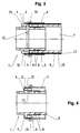
- the insulating ring 12 As shown in Fig. 3, the insulating ring 12, as at the beginning already mentioned, a direct contact of the front of the Composite pipe 7 with the brass press fitting 1 prevented by the fully inserted composite pipe 7th flattened so that the tongues 15 through the recesses 3 of the The outer circumferential rib 2 protrude outwards, which indicates that the composite pipe 7 is correctly inserted for pressing. Should the pipe connection, e.g. at the Initiate the pressing process, the composite pipe 7 somewhat slip, this is easy to recognize on the tongues 15 and can thus be corrected. An insight into how the state of the Technology is not necessary and often not possible. In some cases you can even feel with your fingers whether the tongues 15 with the intended dimension from the recesses 3 of Protruding the outer circumferential rib 2 and thus the composite pipe 7 in in its correct position.
Abstract
Das Preßfitting (1) weist einen Stützansatz (5) auf, der das Ende eines Kunststoff-Verbundrohres (7) aufnimmt. Eine Außenumfangsrippe (2) des Fittings (1) ist mit zwei diametral gegenüberliegenden Ausnehmungen (3) versehen. Ein Isolierring (12) aus Kunststoff ist nach Art einer gewölbten Federscheibe in Richtung zum Verbundrohr (7) zweimal konvex gewölbt. In der Mitte jeder konvexen Wölbung ist eine achsparallele Zunge (15) einstückig angeformt, die in die zugehörige Ausnehmung (3) der Außenumfangsrippe (2) eingreift und bei völlig eingeschobenem Verbundrohr (7) in axialer Richtung aus der Ausnehmung (3) der Außenumfangsrippe (2) herausragt. Dadurch wird die richtige Stellung des Verbundrohres (7) sichtbar und fühlbar angezeigt. Der Isolierring (12) verhindert außerdem einen direkten Kontakt der Aluminium-Metallschicht (11) des Verbundrohres (7) mit dem aus Messing bestehenden Pressfitting (1). <IMAGE>The press fitting (1) has a support projection (5) which receives the end of a plastic composite pipe (7). An outer peripheral rib (2) of the fitting (1) is provided with two diametrically opposite recesses (3). An insulating ring (12) made of plastic is curved convex twice in the manner of a curved spring washer in the direction of the composite pipe (7). In the middle of each convex curvature, an axially parallel tongue (15) is integrally formed, which engages in the associated recess (3) of the outer circumferential rib (2) and in the axial direction from the recess (3) of the outer circumferential rib (3) when the composite tube (7) is fully inserted. 2) protrudes. As a result, the correct position of the composite pipe (7) is visibly and tangibly displayed. The insulating ring (12) also prevents direct contact of the aluminum-metal layer (11) of the composite pipe (7) with the brass press fitting (1). <IMAGE>
Description
Die Erfindung bezieht sich auf ein Pressfitting für Kunststoff-Verbundrohre, die aus einer Innenschicht und einer Außenschicht aus Kunststoff und einer Mittelschicht aus Metall, vorzugsweise Aluminium, bestehen, wobei das Fitting einen Stützansatz aufweist, auf den das Ende des Verbundrohres gegen einen Isolierring aus Kunststoff und einen Außenbund des Fittings aufschiebbar und durch eine Preßhülse fixierbar istThe invention relates to a press fitting for Plastic composite pipes consisting of an inner layer and a Outer layer made of plastic and a middle layer made of metal, preferably aluminum, exist, the fitting one Has support approach against which the end of the composite pipe an insulating ring made of plastic and an outer collar of the Fittings can be pushed on and fixed with a press sleeve
Aus der DE 44 41 373 C2 bekannte Preßfittings dieser Art werden zum Anschließen von Kunststoff-Verbundrohren an Armaturen verwendet. Der Außenbund dieses bekannten Preßfittings ist im Axialschnitt gesehen L-förmig ausgebildet, wobei der achsparallel verlaufende freie Schenkel des Außenbundes an mehreren Stellen jeweils eine Ausnehmung aufweist, die sich radial erstreckt und eine Sichtkontrolle des bis zum Anschlag (Bund) auf eine Stützhülse aufgeschobenen Kunststoff-Verbundrohres ermöglicht. Um diese radialen Ausnehmungen gegen Verschmutzung zu schützen, müßte dieser Bereich durch einen entsprechenden transparenten Kunststoffring abgedeckt werden. Die Transparenz eines solchen Ringes, der in der DE 44 41 373 C2 allerdings nicht erwähnt ist, ist notwendig wegen der erwünschten Sichtkontrolle der Einschubstellung des Verbundrohres. Dennoch ist die Sichtkontrolle durch diesen Ring insbesondere an unzugänglichen Einbauorten stark behindert.Known press fittings of this type from DE 44 41 373 C2 are used to connect plastic composite pipes to fittings used. The outer collar of this known press fitting is in Axial section seen L-shaped, the axially parallel free legs of the outer collar several places each has a recess that extends radially and a visual inspection of the stop (Collar) on a support sleeve pushed plastic composite pipe enables. To counter these radial recesses To protect pollution, this area should be protected by a appropriate transparent plastic ring are covered. The transparency of such a ring, which in DE 44 41 373 C2 However, not mentioned is necessary because of desired visual inspection of the insertion position of the Composite pipe. Nevertheless, the visual inspection is through this ring severely hampered, particularly in inaccessible installation locations.
Der weitere Nachteil dieses bekannten Preßfittings, daß die
Aluminiumschicht des Kunststoff-Metall-Verbundrohres mit dem in
der Regel aus Messing bestehenden Fitting in Berührung kommt,
was zur Verhinderung von Korrosion vermieden werden sollte, wird
bei einer abdichtenden Verbindung von Kunststoff-Metall-Kunststoff-Verbundrohren
nach der EP 0 611 911 A1 durch ein
ringförmiges Kunststoffteil vermieden, das auf das Ende der
Presshülse aufgerastet wird und so ausgebildet ist, daß es mit
einem Innenflansch die Stirnfläche des Verbundrohres abdeckt und
somit einen Kontakt der an der Stirnfläche des Verbundrohres
freiliegenden Metalleinlage mit dem Messingfitting verhindert.
Bei dieser Ausführungsform ist jedoch eine Sichtkontrolle des
richtigen Sitzes des Verbundrohres am Anschlag des Fittings
nicht möglich.The further disadvantage of this known press fitting that the
Aluminum layer of the plastic-metal composite pipe with the in
usually made of brass comes into contact,
what should be avoided to prevent corrosion
with a sealing connection of plastic-metal-plastic composite pipes
according to
Der Erfindung liegt die Aufgabe zugrunde, ein Preßfitting für Kunststoff-Verbundrohre zu entwickeln, das sowohl die Sichtkontrolle des richtigen Sitzes des Verbundrohres zwischen Fitting und Presshülse als auch eine Isolierung zwischen der Stirnfläche des Verbundrohres und dem Fitting ermöglicht.The invention has for its object a press fitting to develop for plastic composite pipes that both Visual inspection of the correct seat of the composite pipe between Fitting and compression sleeve as well as insulation between the Front face of the composite pipe and the fitting allows.
Diese Aufgabe ist erfindungsgemäß gelöst durch ein
Preßfitting mit den Merkmalen des Patentanspruchs 1.This object is achieved by a
Press fitting with the features of
Die Unteransprüche beinhalten vorteilhafte und zweckmäßige Weiterbildungen der Erfindung.The sub-claims contain advantageous and expedient Developments of the invention.
Die erfindungsgemäße Ausbildung des Pressfittings ermöglicht in jeder Lage eine gut sichtbare und ggf. sogar fühlbare Kontrolle des richtigen Sitzes des Verbundrohres zwischen Fitting und Presshülse, wenn der federnde Isolierring aus Kunststoff , der wie eine Federscheibe vorgebogen ist, durch das eingeschobene Verbundrohr flachgedrückt wird, so daß die Zungen in axialer Richtung aus den Ausnehmungen der Außenumfangsrippe des Fittings sichtbar und fühlbar herausragen. Dabei ist auch ohne weiteres erkennbar, wenn bei weiterer Bearbeitung der Rohrverbindung, z.B. bei Einleitung des Pressvorgangs, das Verbundrohr gegenüber dem Fitting verrutschen sollte. Zudem verhindert der Isolierring einen direkten Kontakt der Stirnfläche des Verbundrohres mit dem Fitting.The formation of the press fitting according to the invention enables a clearly visible and possibly even palpable in every position Check the correct fit of the composite pipe between Fitting and compression sleeve when the resilient insulating ring is off Plastic that is pre-bent like a spring washer through which inserted composite pipe is flattened so that the tongues in the axial direction from the recesses of the outer peripheral rib of the fitting protrude visibly and noticeably. It is also readily recognizable if the Pipe connection, e.g. upon initiation of the pressing process, the Composite pipe should slip against the fitting. In addition the insulating ring prevents direct contact of the End face of the composite pipe with the fitting.
Ein Ausführungsbeispiel des erfindungsgemäßen Pressfittings ist in der Zeichnung dargestellt. Dabei zeigt
- Fig. 1
- einen Längsschnitt des Fittings mit noch nicht vollständig eingeschobenem Verbundrohr,
- Fig. 2
- einen Schnitt nach der Linie II-II in Fig. 1,
- Fig. 3
- den Längsschnitt nach Fig. 1 mit vollständig eingeschobenem, aber noch nicht verpresstem Verbundrohr,
- Fig. 4
- im Längsschnitt das Fitting ohne Verbundrohr,
- Fig. 5
- den Längsschnitt nach Fig. 4 um 90° verdreht,
- Fig. 6
- in perspektivischer Darstellung das Fitting ohne Presshülse und Verbundrohr und
- Fig. 7
- in perspektivischer Darstellung den Isolierring des Preßfittings.
- Fig. 1
- a longitudinal section of the fitting with the composite pipe not yet fully inserted,
- Fig. 2
- 2 shows a section along the line II-II in FIG. 1,
- Fig. 3
- 1 with the fully inserted but not yet pressed composite pipe,
- Fig. 4
- in longitudinal section the fitting without composite pipe,
- Fig. 5
- 4 rotated by 90 °,
- Fig. 6
- in perspective the fitting without compression sleeve and composite pipe and
- Fig. 7
- in perspective the insulating ring of the press fitting.
Das Pressfitting 1 aus Messing gemäß den Fign. 1 und 6 weist
eine Außenumfangsrippe 2 mit Ausnehmungen 3 auf. Zum Pressfitting
1 gehört ferner eine Presshülse 4 aus Metall, z.B. Aluminium, die
in den einzelnen Zeichnungsfiguren in unverpresstem Zustand
dargestellt ist. The brass press fitting 1 according to FIGS. 1 and 6 points
an outer
Ein Stützansatz 5 des Fittings 1 weist, wie üblich,
Umfangsrillen 6 auf, in die ein Kunststoff-Verbundrohr 7 beim
Verpressen der Presshülse 4 formschlüssig eingedrückt wird. In
einigen Umfangsrillen 6 können Dichtringe 8 eingelegt sein. In
Fig. 1 ist das Verbundrohr 7, das eine innere Kunststoffschicht 9
und eine äußere Kunststoffschicht 10 sowie eine Zwischenschicht
11 aus Metall, z.B. Aluminium, aufweist, noch nicht ganz auf den
Stützansatz 5 des Fittings 1 aufgeschoben.A
Zwischen dem Stützansatz 5 und der Presshülse 4 des
Preßfittings 1 ist ein Isolierring 12 vorgesehen, der aus
Kunststoff nach Art einer mehrfach gewölbten Federscheibe
vorgebogen ist, und zwar so, daß zwei in Richtung zum Verbundrohr
7 konvexe Wölbungen 13 und zwei in Richtung zum Verbundrohr 7
konkave Wölbungen 14 vorhanden sind. In der Mitte der konvexen
Wölbungen 13 sind achsparallele Zungen 15 einstückig angeformt.
In der Mitte der konkaven Wölbungen 14 sind radial nach innen
einstückig angeformte Ansätze 16 am Isolierring 12 vorgesehen,
die in eine separate Außenumfangsnut 17 des Stützansatzes 5
eingreifen und den Isolierring 12 vor der Montage der
Rohrverbindung unverlierbar halten. Den Bereich des Isolierringes
12 und einen Endbereich der Presshülse 4 überdeckt ein
Kunststoffring 18, der in eine Außenumfangsnut 19 der
Außenumfangsrippe 2 des Fittings 1 eingerastet ist.Between the
Wie Fig. 3 zeigt, wird der Isolierring 12, der, wie eingangs
bereits erwähnt, einen direkten Kontakt der Stirnseite des
Verbundrohres 7 mit dem aus Messing bestehenden Pressfitting 1
verhindert, durch das völlig eingeschobene Verbundrohr 7
plattgedrückt , so daß die Zungen 15 durch die Ausnehmungen 3 der
Außenumfangsrippe 2 hindurch nach außen herausragen, was anzeigt,
daß das Verbundrohr 7 zum Verpressen richtig eingesetzt ist.
Sollte bei weiterer Montage der Rohrverbindung, z.B. beim
Einleiten des Pressvorganges, das Verbundrohr 7 etwas
verrutschen, so ist dies an den Zungen 15 leicht zu erkennen und
kann somit korrigiert werden. Ein Einblick, wie beim Stand der
Technik, ist dabei nicht erforderlich und auch vielfach nicht
möglich. In manchen Fällen kann man sogar mit den Fingern fühlen,
ob die Zungen 15 mit vorgesehenem Maß aus den Ausnehmungen 3 der
Außenumfangsrippe 2 herausragen und damit das Verbundrohr 7 in
seiner richtigen Stellung sitzt.As shown in Fig. 3, the
Claims (3)
Applications Claiming Priority (2)
| Application Number | Priority Date | Filing Date | Title |
|---|---|---|---|
| DE10022893A DE10022893C1 (en) | 2000-05-10 | 2000-05-10 | Compression pipe fitting for plastics connection pipe has spring insulation ring contacted by end of pipe for providing visual indication of correct positioning |
| DE10022893 | 2000-05-10 |
Publications (2)
| Publication Number | Publication Date |
|---|---|
| EP1154187A2 true EP1154187A2 (en) | 2001-11-14 |
| EP1154187A3 EP1154187A3 (en) | 2002-02-06 |
Family
ID=7641527
Family Applications (1)
| Application Number | Title | Priority Date | Filing Date |
|---|---|---|---|
| EP01110537A Withdrawn EP1154187A3 (en) | 2000-05-10 | 2001-04-28 | Compression fitting for plastic composite pipes |
Country Status (5)
| Country | Link |
|---|---|
| US (1) | US6450549B1 (en) |
| EP (1) | EP1154187A3 (en) |
| JP (1) | JP3564422B2 (en) |
| DE (1) | DE10022893C1 (en) |
| PL (1) | PL347355A1 (en) |
Cited By (4)
| Publication number | Priority date | Publication date | Assignee | Title |
|---|---|---|---|---|
| DE202007018890U1 (en) | 2007-03-22 | 2009-09-24 | Geberit International Ag, Jona | Fitting for water pipes and pipe connection with such a fitting |
| EP2112416A1 (en) | 2008-04-25 | 2009-10-28 | Comap | Instant connection for at least one tube |
| FR3106388A1 (en) | 2020-01-20 | 2021-07-23 | A.Raymond Et Cie | Device for connecting a tubular element |
| USD959516S1 (en) * | 2020-01-23 | 2022-08-02 | Applied Materials, Inc. | Compression fitting |
Families Citing this family (19)
| Publication number | Priority date | Publication date | Assignee | Title |
|---|---|---|---|---|
| DE20115436U1 (en) * | 2001-09-19 | 2003-02-20 | Voss Automotive Gmbh | Connection device for fluid lines |
| ATE333623T1 (en) * | 2002-07-01 | 2006-08-15 | Geberit Technik Ag | CONNECTION BETWEEN A PIPE AND A FITTING, FITTING FOR SUCH A CONNECTION AND METHOD FOR ASSEMBLY |
| CN2814090Y (en) * | 2005-03-31 | 2006-09-06 | 佛山市日丰企业有限公司 | Clipper pressing type metal pipe fittings connecting device |
| DE502005001736D1 (en) * | 2005-05-09 | 2007-11-29 | Herz Armaturen Gmbh | Connecting arrangement for line system with ring element |
| DE102005028558B3 (en) * | 2005-06-21 | 2007-01-04 | Uponor Innovation Ab | Press fitting for a pipe has fitting and supporting bodies for a connecting pipe to be pushed onto it and a press-on sleeve with a holding end for holding the press-on sleeve on the fitting body |
| DE102005038476B4 (en) * | 2005-08-13 | 2020-05-28 | Eaton Fluid Power Gmbh | Device and method for connecting a hydraulic hose to a connection nipple |
| CN200943796Y (en) * | 2006-09-14 | 2007-09-05 | 佛山市日丰企业有限公司 | Press-fitting pipe fitting |
| US9611958B1 (en) | 2007-01-05 | 2017-04-04 | Zurn Industries, Llc | Combination mechanical/fusion pipe fitting with push connect coupling arrangement |
| PT2019243E (en) * | 2007-07-26 | 2011-05-09 | Uponor Innovation Ab | Press fitting for a pipe |
| US20090108581A1 (en) * | 2007-10-26 | 2009-04-30 | Scripps Secured Data, Inc. Dba Holocom Networks | Flanged sleeve connector for secure conduit system |
| DE202007018209U1 (en) | 2007-12-28 | 2009-05-07 | Werner, Gabriele | Connection element for a line system |
| BRPI0804302B1 (en) * | 2008-10-07 | 2020-09-15 | Embraco Indústria De Compressores E Soluções Em Refrigeração Ltda | OIL PUMP ASSEMBLY ARRANGEMENT IN A COOLING COMPRESSOR |
| EP2603725B1 (en) * | 2010-08-10 | 2017-03-22 | Netafim Ltd. | Fitting assembly |
| ES2630020T3 (en) * | 2011-03-28 | 2017-08-17 | Flexin Group S.R.L. | Flexible hose connector |
| DE202011004544U1 (en) * | 2011-03-29 | 2011-05-26 | Ipa Produktions- Und Vertriebsges.M.B.H. | Press connection for plastic pipes |
| MX2016012306A (en) * | 2014-04-24 | 2016-11-30 | Henn Gmbh & Co Kg | Connector assembly. |
| GB2526576B (en) * | 2014-05-28 | 2016-07-20 | Pegler Yorkshire Group Ltd | Improved press-fit pipe coupling |
| US9551445B2 (en) | 2014-06-09 | 2017-01-24 | Cooper Technologies Company | Conduit receivers |
| US10302230B2 (en) | 2014-06-09 | 2019-05-28 | Eaton Intelligent Power Limited | Field serviceable conduit receivers |
Citations (4)
| Publication number | Priority date | Publication date | Assignee | Title |
|---|---|---|---|---|
| US526679A (en) * | 1894-10-02 | Fire-escape | ||
| US4925217A (en) * | 1988-10-24 | 1990-05-15 | Huron Products Corporation | Quick connector with visual checking method |
| DE19735319A1 (en) * | 1997-08-14 | 1999-02-18 | Bayerische Motoren Werke Ag | Electronic controller system for road vehicle systems |
| EP0940620A1 (en) * | 1998-03-02 | 1999-09-08 | Comap Abbeville S.A. | Compression fitting for plastic pipes |
Family Cites Families (7)
| Publication number | Priority date | Publication date | Assignee | Title |
|---|---|---|---|---|
| US3578360A (en) * | 1969-07-16 | 1971-05-11 | Perfex Plastics Inc | A fitting for a liner pipe formed of polyethylene |
| US4114250A (en) * | 1976-08-16 | 1978-09-19 | Dent Robert K | Method of fixing a threaded tube to a threaded shank or nipple |
| NZ200846A (en) * | 1981-06-10 | 1985-11-08 | Unilever Plc | Hose end fitting:collar swages into body recess |
| DE4304680C1 (en) * | 1993-02-16 | 1994-04-28 | Kirchner Fraenk Rohr | Coupling for plastics clad metal hose - has crimped coupling sleeve with plastics lip for protecting end of hose and has raised section incorporating sealing ring |
| DE4441373C2 (en) * | 1994-11-21 | 1997-12-04 | Kirchner Fraenk Rohr | Pipe connection, in particular for pipes with at least one plastic layer |
| SI0879985T1 (en) * | 1997-05-20 | 2000-12-31 | Herz Armaturen Ges.M.B.H. | Compression fitting for pipes |
| US6086115A (en) * | 1998-07-17 | 2000-07-11 | Morris Coupling Co. | Coupling with ferrule for crimping and swaging |
-
2000
- 2000-05-10 DE DE10022893A patent/DE10022893C1/en not_active Expired - Fee Related
-
2001
- 2001-04-28 EP EP01110537A patent/EP1154187A3/en not_active Withdrawn
- 2001-04-30 PL PL01347355A patent/PL347355A1/en not_active IP Right Cessation
- 2001-05-07 US US09/850,722 patent/US6450549B1/en not_active Expired - Fee Related
- 2001-05-10 JP JP2001139837A patent/JP3564422B2/en not_active Expired - Fee Related
Patent Citations (4)
| Publication number | Priority date | Publication date | Assignee | Title |
|---|---|---|---|---|
| US526679A (en) * | 1894-10-02 | Fire-escape | ||
| US4925217A (en) * | 1988-10-24 | 1990-05-15 | Huron Products Corporation | Quick connector with visual checking method |
| DE19735319A1 (en) * | 1997-08-14 | 1999-02-18 | Bayerische Motoren Werke Ag | Electronic controller system for road vehicle systems |
| EP0940620A1 (en) * | 1998-03-02 | 1999-09-08 | Comap Abbeville S.A. | Compression fitting for plastic pipes |
Cited By (7)
| Publication number | Priority date | Publication date | Assignee | Title |
|---|---|---|---|---|
| DE202007018890U1 (en) | 2007-03-22 | 2009-09-24 | Geberit International Ag, Jona | Fitting for water pipes and pipe connection with such a fitting |
| DE202007019164U1 (en) | 2007-03-22 | 2010-10-28 | Geberit International Ag | Fitting for water pipes |
| EP2246607A1 (en) | 2007-03-22 | 2010-11-03 | Geberit International AG | Fitting for water pipes |
| EP2112416A1 (en) | 2008-04-25 | 2009-10-28 | Comap | Instant connection for at least one tube |
| FR3106388A1 (en) | 2020-01-20 | 2021-07-23 | A.Raymond Et Cie | Device for connecting a tubular element |
| WO2021148737A1 (en) | 2020-01-20 | 2021-07-29 | A. Raymond Et Cie | Device for connecting a tubular element |
| USD959516S1 (en) * | 2020-01-23 | 2022-08-02 | Applied Materials, Inc. | Compression fitting |
Also Published As
| Publication number | Publication date |
|---|---|
| JP3564422B2 (en) | 2004-09-08 |
| EP1154187A3 (en) | 2002-02-06 |
| US6450549B1 (en) | 2002-09-17 |
| JP2002031283A (en) | 2002-01-31 |
| DE10022893C1 (en) | 2001-06-28 |
| PL347355A1 (en) | 2001-11-19 |
Similar Documents
| Publication | Publication Date | Title |
|---|---|---|
| DE10022893C1 (en) | Compression pipe fitting for plastics connection pipe has spring insulation ring contacted by end of pipe for providing visual indication of correct positioning | |
| EP2246607B1 (en) | Fitting for water pipes | |
| EP2469142B1 (en) | Press fitting and its use | |
| DE102007008066B4 (en) | fitting | |
| EP1361385B1 (en) | Press fitted pipe joint | |
| DE102006013899B3 (en) | Insertion coupling to connect two fluid lines has assembly indicator next to locking projection to project beyond locking projection sector of holding arm | |
| EP2864685A1 (en) | Connection device for pipe lines | |
| EP1564469A1 (en) | Fitting for a press joint | |
| EP2413012B1 (en) | Connector | |
| DE19702289C2 (en) | Arrangement for connecting pipes or hoses with fittings or fittings | |
| EP1063462B2 (en) | Connecting piece with a plastic fitting | |
| DE19854854B4 (en) | Connection device with a socket | |
| DE202011004259U1 (en) | hose coupling | |
| DE102012210342A1 (en) | Hose coupling, in particular for high-pressure hydraulic lines of a release system | |
| EP2716824A2 (en) | Hose, in particular a shower hose | |
| EP1267113B1 (en) | Connection member | |
| DE102008020833A1 (en) | press connection | |
| EP0390747A2 (en) | Sealing connection for multilayer plastic pipes | |
| EP1431643B1 (en) | Pressfitting and holding element for a pressfitting joint | |
| EP3124848A1 (en) | Connection fitting for a fluid conduit | |
| DE202011107927U1 (en) | Connecting device for connecting two pipes | |
| DE19946133A1 (en) | Lip sealing ring for pipe joints comprises circumferential sealing lips which radially protrude outwards and/or inwards from ring body element | |
| EP2667074B1 (en) | System with clamp parts for connecting tubes | |
| DE10345286B4 (en) | Connecting piece for a fluid-tight connection device between two pipe elements and pipe connecting device with such a connector | |
| DE102017107395A1 (en) | pipe seal |
Legal Events
| Date | Code | Title | Description |
|---|---|---|---|
| PUAI | Public reference made under article 153(3) epc to a published international application that has entered the european phase |
Free format text: ORIGINAL CODE: 0009012 |
|
| AK | Designated contracting states |
Kind code of ref document: A2 Designated state(s): AT BE CH CY DE DK ES FI FR GB GR IE IT LI LU MC NL PT SE TR |
|
| AX | Request for extension of the european patent |
Free format text: AL;LT;LV;MK;RO;SI |
|
| PUAL | Search report despatched |
Free format text: ORIGINAL CODE: 0009013 |
|
| AK | Designated contracting states |
Kind code of ref document: A3 Designated state(s): AT BE CH CY DE DK ES FI FR GB GR IE IT LI LU MC NL PT SE TR |
|
| AX | Request for extension of the european patent |
Free format text: AL;LT;LV;MK;RO;SI |
|
| 17P | Request for examination filed |
Effective date: 20020521 |
|
| AKX | Designation fees paid |
Free format text: AT BE CH CY DE DK ES FI FR GB GR IE IT LI LU MC NL PT SE TR |
|
| 17Q | First examination report despatched |
Effective date: 20040518 |
|
| GRAP | Despatch of communication of intention to grant a patent |
Free format text: ORIGINAL CODE: EPIDOSNIGR1 |
|
| STAA | Information on the status of an ep patent application or granted ep patent |
Free format text: STATUS: THE APPLICATION IS DEEMED TO BE WITHDRAWN |
|
| 18D | Application deemed to be withdrawn |
Effective date: 20050826 |