EP1154190B1 - Apparatus relating to tube couplings - Google Patents
Apparatus relating to tube couplings Download PDFInfo
- Publication number
- EP1154190B1 EP1154190B1 EP01304106A EP01304106A EP1154190B1 EP 1154190 B1 EP1154190 B1 EP 1154190B1 EP 01304106 A EP01304106 A EP 01304106A EP 01304106 A EP01304106 A EP 01304106A EP 1154190 B1 EP1154190 B1 EP 1154190B1
- Authority
- EP
- European Patent Office
- Prior art keywords
- tube
- coupling body
- coupling
- cap
- engage
- Prior art date
- Legal status (The legal status is an assumption and is not a legal conclusion. Google has not performed a legal analysis and makes no representation as to the accuracy of the status listed.)
- Expired - Lifetime
Links
Images


Classifications
-
- F—MECHANICAL ENGINEERING; LIGHTING; HEATING; WEAPONS; BLASTING
- F16—ENGINEERING ELEMENTS AND UNITS; GENERAL MEASURES FOR PRODUCING AND MAINTAINING EFFECTIVE FUNCTIONING OF MACHINES OR INSTALLATIONS; THERMAL INSULATION IN GENERAL
- F16L—PIPES; JOINTS OR FITTINGS FOR PIPES; SUPPORTS FOR PIPES, CABLES OR PROTECTIVE TUBING; MEANS FOR THERMAL INSULATION IN GENERAL
- F16L37/00—Couplings of the quick-acting type
- F16L37/08—Couplings of the quick-acting type in which the connection between abutting or axially overlapping ends is maintained by locking members
- F16L37/12—Couplings of the quick-acting type in which the connection between abutting or axially overlapping ends is maintained by locking members using hooks, pawls or other movable or insertable locking members
-
- F—MECHANICAL ENGINEERING; LIGHTING; HEATING; WEAPONS; BLASTING
- F16—ENGINEERING ELEMENTS AND UNITS; GENERAL MEASURES FOR PRODUCING AND MAINTAINING EFFECTIVE FUNCTIONING OF MACHINES OR INSTALLATIONS; THERMAL INSULATION IN GENERAL
- F16L—PIPES; JOINTS OR FITTINGS FOR PIPES; SUPPORTS FOR PIPES, CABLES OR PROTECTIVE TUBING; MEANS FOR THERMAL INSULATION IN GENERAL
- F16L37/00—Couplings of the quick-acting type
- F16L37/08—Couplings of the quick-acting type in which the connection between abutting or axially overlapping ends is maintained by locking members
- F16L37/084—Couplings of the quick-acting type in which the connection between abutting or axially overlapping ends is maintained by locking members combined with automatic locking
- F16L37/098—Couplings of the quick-acting type in which the connection between abutting or axially overlapping ends is maintained by locking members combined with automatic locking by means of flexible hooks
- F16L37/0985—Couplings of the quick-acting type in which the connection between abutting or axially overlapping ends is maintained by locking members combined with automatic locking by means of flexible hooks the flexible hook extending radially inwardly from an outer part and engaging a bead, recess or the like on an inner part
-
- F—MECHANICAL ENGINEERING; LIGHTING; HEATING; WEAPONS; BLASTING
- F16—ENGINEERING ELEMENTS AND UNITS; GENERAL MEASURES FOR PRODUCING AND MAINTAINING EFFECTIVE FUNCTIONING OF MACHINES OR INSTALLATIONS; THERMAL INSULATION IN GENERAL
- F16L—PIPES; JOINTS OR FITTINGS FOR PIPES; SUPPORTS FOR PIPES, CABLES OR PROTECTIVE TUBING; MEANS FOR THERMAL INSULATION IN GENERAL
- F16L2201/00—Special arrangements for pipe couplings
- F16L2201/10—Indicators for correct coupling
Definitions
- This invention relates to couplings for receiving tubes or stuffer pins or the like such as disclosed in EP-A-00300504.8 and EP-A-756125.
- US-A-5,658,020 discloses a quick connector for fast connection of fluid carrying assemblies and includes a connector body for the connector components and a redundant clip, which is adapted to engage an upset bead of the male tube.
- the redundant clip is generally L-shaped and includes a retaining head that is inserted into the connector body and is adapted to engage the upset bead.
- a body portion which extends along the side of the connector body and in the preferred embodiment is contoured to mate with the , connector body, extends between the retaining head and a base member.
- the base includes a camming edge for facilitating the insertion of the retainer head into the connector body.
- WO 98/38 450 A discloses a releasable connector for connecting tubing such as used in fuel lines and has a display member to indicate when positive locking has occurred.
- the display member is attached to the outside of the housing of the connector and has a strap supporting a cover portion.
- the cover portion has a pair of resilient flanges which are insertable into an opening in the housing of the connector.
- the flanges extend into a chamber to engage an annular ring of a conventional male tube end.
- the annular portion of the tube end displaces the flanges of the display member after passing through a locking member contained in the housing of the connector. In this way, the tamper indicator indicates that the tube end has been positively received in the locking position.
- the European Patent Publication No. 0829671 describes and illustrates a number of connectors for latching engagement with tubes or stuffer pins in which a tube must be pressed into the connector body for the latching arrangement provided to operate and retain the tube in the body.
- a raised bead is provided on the tube with which the latch in the coupling body engages.
- US-A-5,931,509 discloses a tube coupling comprising all the features of the preamble of claim 1, having a connection verification and secondary latch device.
- the connector ring has a primary latching mechanism which engages a first annular projection on the tube and a second latching mechanism which engages a second annular projection on the tube.
- the latching mechanisms extend outside of the housing connector which receives the conduit thus allowing an inspection of the assembly to ensure that a complete connection by both latching mechanisms has been accomplished.
- the invention provides a connector assembly, comprising a tubular conduit including a first end having first and second annular projections disposed a predetermined distance from said first end, a retainer element including primary latching means releasably engageable with said first annular projection and secondary latching means extending from and attached to said primary latching means, means for sealing the connector assembly, and a housing for receiving said first end of said tubular conduit, said housing including at least one blocking wall, whereby upon fully inserting said tubular conduit within said housing, said primary latching means engage said first annular projection of said tubular conduit and said secondary latching means engage said second annular projection of said tubular conduit.
- This invention provides a coupling for a tube having a feature spaced from an end of the tube for engagement by latching devices, the coupling comprising a coupling body having a throughway open at one end to receive an end portion of the tube, a seal mounted in the coupling body at a location spaced from said open end thereof to engage and seal with the outer periphery of the tube, a first latching device disposed within the coupling body having at least one latch to engage automatically with the feature on the tube when the tube has been inserted sufficiently into the throughway to engage with the seal to thereby retain the tube in the coupling body, and a second, manually operable latching device disposed externally of the coupling body mounted on the coupling body, manually moveable between one operative position in which the second latching device is engageable with the feature on the tube when the tube has been inserted into the coupling body sufficiently for the first latching device to engage to provide a second independent retention for the tube in the coupling body, and an inoperative position withdrawn from the tube to allow release of the tube from
- the cap and coupling body Preferably have slots through which the detent on the leg can project to engage a feature on the tube which is also engaged by the first latching device within the coupling body.
- interengaging abutment means are provided on the detent and coupling body to retain the detent engaged in said slots in the coupling body and cap.
- the leg is hingedly mounted to the cap and when the tube is inserted into the coupling body the second latching device is arranged to engage a second feature on the tube which is located externally of the coupling body thereby to retain the tube in the coupling body.
- the detent on the arm comprises a C-shaped clip to snap around the tube.
- the coupling comprises a coupling body 10 having a stepped throughway 11 open at one end 12 of the coupling body to receive a tube end fitting indicated at 13.
- the tube end fitting in this case is a standard male end form to SAE (Society of Automotive Engineers) J2044. Other similar fittings are equally applicable.
- the throughway 11 is stepped at 14 to an enlonged diameter portion 15 to receive the tube end 13 with a close or interference fit.
- the throughway is stepped at 16 to a second enlarged diameter portion 17 in which a pair of 0-ring seals 18 are located with a spacer 19 between them to seal on the outside of the tube end 13.
- the throughway has a further step 20 to an enlarged diameter portion 21 which extends through to the open end of the throughway at 12.
- a first internal latch is located within the coupling body 10 and comprises a sleeve 22 extending through the enlarged diameter portion 21 of the throughway 21 and having a reduced diameter end portion 23 to engage in portion 17 of the throughway.
- the sleeve has three integral resilient legs 24 disposed over three quarters of the circumference of the sleeve and projecting towards the open end of the coupling.
- the legs have latch members 25 at their distal ends which have outwardly extending abutments which engage in radial opening 26 through the wall of the coupling body and have inwardly projecting teeth 25a to engage a raised annular abutment or bead 27 on the tube end.
- European patent publication no. 0829671 for a more detailed description of the form of the latch members and the manner of their engagement with the raised abutment on the tube end and in the openings 26 of the coupling body wall to retain the tube end in the coupling.
- the sleeve 22 has integral struts 28 projecting between the teeth to the open end of the coupling body.
- the struts are formed integrally with an end cap 30 encircling the end of the coupling body and which is adjustable axially on the coupling body to adjust the position of the internal latches for release of a tube end from the coupling body as described in our previous European publication.
- the legs/internal latch members in the coupling body are provided over three quarters of the circumference of the sleeve.
- the remaining quarter of the sleeve is disposed opposite a slot 31 formed with the wall of the coupling body and a corresponding slot 32 formed in the wall of the cap.
- the wall of the cap has an extension 33 in alignment with the slot 30 and a leg 34 is attached to the extension by an integral hinge 35.
- the leg has a detent 36 at its distal end shaped to extend through the slots in the cap and coupling body and to engage the end of the tube behind the raised rib 27 to provide a secondary, external latch for holding the tube in place in the coupling body.
- the end of the detent 36 is radiused as shown at 37 with a corresponding radius to the tube end to provide a close engagement between the abutment and tube.
- the detent is formed with abutments 36a which snap behind abutments on either side of the slot in the coupling body to retain the detent in the engaged position.
- the hinge 35 between the leg 34 and cap extension 33 has a moulded characteristic such that the leg 34 snaps towards the coupling body when adjacent the body and snaps outwardly of the body when withdrawn beyond an intermediate position in its travel. The leg then stands outwardly of the coupling body and provides a clear visual or tactile indication that it is not engaged.
- Figures 7 to 11 show a broadly similar arrangement except that in this case the tube end 13 has a second raised bead 40 beyond the first bead or abutment 27 and the detent 36 on the leg 34 is arranged to project beyond body in the closed position and to engage the tube end 13 beyond the second bead 40.
- the abutment does not fit between slots in the cap and coupling body so the coupling body may be provided with four internal latches to engage the bead 27 rather than three of the first embodiments.
- the detent is in the form of a C-shaped clip which is a snap fit on the tube end. The arrangement is otherwise much the same as that of Figure 1.
- Figures 1 to 6 can also be adapted to have four latch members within the coupling body and one pair of members spaced sufficiently to accommodate the external manual latch between them.
- FIGs 12 to 15 shows similar arrangements applied to stuffer pins rather than tube ends.
Description
- This invention relates to couplings for receiving tubes or stuffer pins or the like such as disclosed in EP-A-00300504.8 and EP-A-756125.
- US-A-5,658,020 discloses a quick connector for fast connection of fluid carrying assemblies and includes a connector body for the connector components and a redundant clip, which is adapted to engage an upset bead of the male tube. The redundant clip is generally L-shaped and includes a retaining head that is inserted into the connector body and is adapted to engage the upset bead. A body portion, which extends along the side of the connector body and in the preferred embodiment is contoured to mate with the , connector body, extends between the retaining head and a base member. The base includes a camming edge for facilitating the insertion of the retainer head into the connector body.
- WO 98/38 450 A discloses a releasable connector for connecting tubing such as used in fuel lines and has a display member to indicate when positive locking has occurred. The display member is attached to the outside of the housing of the connector and has a strap supporting a cover portion. The cover portion has a pair of resilient flanges which are insertable into an opening in the housing of the connector. The flanges extend into a chamber to engage an annular ring of a conventional male tube end. The annular portion of the tube end displaces the flanges of the display member after passing through a locking member contained in the housing of the connector. In this way, the tamper indicator indicates that the tube end has been positively received in the locking position.
- The European Patent Publication No. 0829671 describes and illustrates a number of connectors for latching engagement with tubes or stuffer pins in which a tube must be pressed into the connector body for the latching arrangement provided to operate and retain the tube in the body. Typically, a raised bead is provided on the tube with which the latch in the coupling body engages.
- US-A-5,931,509 discloses a tube coupling comprising all the features of the preamble of
claim 1, having a connection verification and secondary latch device. The connector ring has a primary latching mechanism which engages a first annular projection on the tube and a second latching mechanism which engages a second annular projection on the tube. The latching mechanisms extend outside of the housing connector which receives the conduit thus allowing an inspection of the assembly to ensure that a complete connection by both latching mechanisms has been accomplished. - The invention provides a connector assembly, comprising a tubular conduit including a first end having first and second annular projections disposed a predetermined distance from said first end, a retainer element including primary latching means releasably engageable with said first annular projection and secondary latching means extending from and attached to said primary latching means, means for sealing the connector assembly, and a housing for receiving said first end of said tubular conduit, said housing including at least one blocking wall, whereby upon fully inserting said tubular conduit within said housing, said primary latching means engage said first annular projection of said tubular conduit and said secondary latching means engage said second annular projection of said tubular conduit.
- There is a need for secondary latches to be fitted to such connectors in certain applications such as in tube connectors used in motor vehicle engine compartments. Moreover there is a requirement that the second latch is engaged in a separate manual operation from the primary assembly operation of inserting a tube in the coupling body and that the second latch only operates properly if the tube has been inserted so the primary latch within the coupling body is successfully engaged.
- It is an object of this invention to meet these additional requirements.
- This invention provides a coupling for a tube having a feature spaced from an end of the tube for engagement by latching devices, the coupling comprising a coupling body having a throughway open at one end to receive an end portion of the tube, a seal mounted in the coupling body at a location spaced from said open end thereof to engage and seal with the outer periphery of the tube, a first latching device disposed within the coupling body having at least one latch to engage automatically with the feature on the tube when the tube has been inserted sufficiently into the throughway to engage with the seal to thereby retain the tube in the coupling body, and a second, manually operable latching device disposed externally of the coupling body mounted on the coupling body, manually moveable between one operative position in which the second latching device is engageable with the feature on the tube when the tube has been inserted into the coupling body sufficiently for the first latching device to engage to provide a second independent retention for the tube in the coupling body, and an inoperative position withdrawn from the tube to allow release of the tube from the coupling body, said second latching device comprises an end cap mounted on the coupling body, the cap having an opening in the end thereof for the tube to extend through into the coupling body wherein said end cap is encircling the open end of the coupling body and has a mounting leg on which the second latch is located, the leg being hinged to the cap to move between said operative and inoperative positions on the cap, the hinged mounting leg including an integral spring adapted to bias the second latching device towards the inoperative position withdrawn from the tube when the second latch device is disengaged from a tube in the coupling body.
- Preferably in the cap and coupling body have slots through which the detent on the leg can project to engage a feature on the tube which is also engaged by the first latching device within the coupling body.
- Furthermore, interengaging abutment means are provided on the detent and coupling body to retain the detent engaged in said slots in the coupling body and cap.
- In one specific arrangement accords to the invention the leg is hingedly mounted to the cap and when the tube is inserted into the coupling body the second latching device is arranged to engage a second feature on the tube which is located externally of the coupling body thereby to retain the tube in the coupling body.
- In the latter arrangement the detent on the arm comprises a C-shaped clip to snap around the tube.
- The following is a description of some specific embodiments of the invention, reference being made to the accompanying drawings in which:
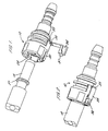
- Figure 1 is a perspective view of a connector and tube end to be located in the connector with a secondary external latch in the released position;
- Figure 2 is a perspective view of a connector of Figure 1 showing the tube end engaged in the connector and the secondary latch in its closed position;
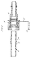
- Figure 3 is a detailed view of a portion of the secondary latch and circle at three on Figure 1;
- Figure 4 is a cross-sectional view of the connector and tube end as shown in Figure 1;
- Figure 5 is a cross-sectional view of the coupling with the tube end partially inserted and the secondary latch engaged as shown in perspective view end 2;
- Figure 6 is a cross-sectional view of the coupling with the tube end fully inserted and the secondary latch engaged as shown in perspective view end 2;
- Figure 7 is a perspective view of an alternative form of coupling and tube end with the tube end in alignment with the connector and an external, secondary latch on the coupling in the released position;
- Figure 8 is a perspective view of the coupling of Figure 7 showing the tube end fully engaged in the coupling and the second external latch in the closed position;
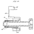
- Figure 9 is a cross-sectional view through the connector and tube end of Figure 7;
- Figure 10 is a cross-sectional view of the connector as shown in Figure 9 with the tube end partially inserted in the coupling;
- Figure 11 is a further view of the connector of Figure 9 with the tube end fully inserted in the coupling and the secondary external latch closed;
- Figures 12 and 13 and 14 and 15 show perspective and cross-sectional views of further connector arrangements with the stuffer pins rather than the tube ends.
-
- Referring firstly to Figures 1 to 6 of the drawings, there is shown a modified form of the tube coupling described as illustrated in our European patent publication no. 0829671 and in particular Figures 9 and 10 of that specification to which reference should be made. The coupling comprises a
coupling body 10 having a stepped throughway 11 open at one end 12 of the coupling body to receive a tube end fitting indicated at 13. The tube end fitting in this case is a standard male end form to SAE (Society of Automotive Engineers) J2044. Other similar fittings are equally applicable. Thethroughway 11 is stepped at 14 to anenlonged diameter portion 15 to receive thetube end 13 with a close or interference fit. The throughway is stepped at 16 to a second enlargeddiameter portion 17 in which a pair of 0-ring seals 18 are located with aspacer 19 between them to seal on the outside of thetube end 13. The throughway has afurther step 20 to an enlargeddiameter portion 21 which extends through to the open end of the throughway at 12. - A first internal latch is located within the
coupling body 10 and comprises asleeve 22 extending through the enlargeddiameter portion 21 of thethroughway 21 and having a reduceddiameter end portion 23 to engage inportion 17 of the throughway. The sleeve has three integral resilient legs 24 disposed over three quarters of the circumference of the sleeve and projecting towards the open end of the coupling. The legs havelatch members 25 at their distal ends which have outwardly extending abutments which engage inradial opening 26 through the wall of the coupling body and have inwardly projectingteeth 25a to engage a raised annular abutment or bead 27 on the tube end. Reference should be made to our European patent publication no. 0829671 for a more detailed description of the form of the latch members and the manner of their engagement with the raised abutment on the tube end and in theopenings 26 of the coupling body wall to retain the tube end in the coupling. - The
sleeve 22 hasintegral struts 28 projecting between the teeth to the open end of the coupling body. The struts are formed integrally with anend cap 30 encircling the end of the coupling body and which is adjustable axially on the coupling body to adjust the position of the internal latches for release of a tube end from the coupling body as described in our previous European publication. - As indicated above, the legs/internal latch members in the coupling body are provided over three quarters of the circumference of the sleeve. The remaining quarter of the sleeve is disposed opposite a
slot 31 formed with the wall of the coupling body and a corresponding slot 32 formed in the wall of the cap. The wall of the cap has anextension 33 in alignment with theslot 30 and aleg 34 is attached to the extension by anintegral hinge 35. The leg has a detent 36 at its distal end shaped to extend through the slots in the cap and coupling body and to engage the end of the tube behind the raisedrib 27 to provide a secondary, external latch for holding the tube in place in the coupling body. The end of thedetent 36 is radiused as shown at 37 with a corresponding radius to the tube end to provide a close engagement between the abutment and tube. The detent is formed with abutments 36a which snap behind abutments on either side of the slot in the coupling body to retain the detent in the engaged position. In the addition, thehinge 35 between theleg 34 andcap extension 33 has a moulded characteristic such that theleg 34 snaps towards the coupling body when adjacent the body and snaps outwardly of the body when withdrawn beyond an intermediate position in its travel. The leg then stands outwardly of the coupling body and provides a clear visual or tactile indication that it is not engaged. - Figures 7 to 11 show a broadly similar arrangement except that in this case the
tube end 13 has a second raisedbead 40 beyond the first bead orabutment 27 and the detent 36 on theleg 34 is arranged to project beyond body in the closed position and to engage thetube end 13 beyond thesecond bead 40. Thus in this arrangement the abutment does not fit between slots in the cap and coupling body so the coupling body may be provided with four internal latches to engage thebead 27 rather than three of the first embodiments. Also the detent is in the form of a C-shaped clip which is a snap fit on the tube end. The arrangement is otherwise much the same as that of Figure 1. - The arrangement of Figures 1 to 6 can also be adapted to have four latch members within the coupling body and one pair of members spaced sufficiently to accommodate the external manual latch between them.
- Figures 12 to 15 shows similar arrangements applied to stuffer pins rather than tube ends.
Claims (5)
- A coupling for a tube (13) having a feature (27) spaced from an end of the tube for engagement by latching devices, the coupling comprising a coupling body (10) having a throughway (11) open at one and (12) to receive an end portion of the tube;
a seal (18) mounted in the coupling body at a location (17) spaced from said open end thereof to engage and seal with the outer periphery of the tube (13),
a first latching device (25) disposed within the coupling body having at least one latch (25a) to engage automatically with the feature (27) on the tube when the tube has been inserted sufficiently into the throughway to engage with the seal to thereby retain the tube in the coupling body,
and a second, manually operable latching device (30, 31, 32) disposed externally of the coupling body mounted on the coupling body, manually moveable between one operative position in which the second latching device is engageable with the feature on the tube when the tube has been inserted into the coupling body sufficiently for the first latching device to engage to provide a second independent retention for the tube in the coupling body, and an inoperative position withdrawn from the tube to allow release of the tube from the coupling body,
said second latching device comprises an end cap mounted on the coupling body, the cap (30) having an opening in the end thereof for the tube to extend through into the coupling body characterised in that said end cap (30) is encircling the open end of the coupling body and has a mounting leg (34) on which the second latch (36) is located, the leg being hinged to the cap to move between said operative and inoperative positions on the cap, the hinged mounting leg including an integral spring (35) adapted to bias the second latching device towards the inoperative position withdrawn from the tube when the second latch device is disengaged from a tube in the coupling body. - A coupling as claimed in claim 1, characterised in that the cap and coupling body have slots (32, 31) through which the detent (36) on the leg (34) can project to engage a feature on the tube which is also engaged by the first latching device within the coupling body.
- A coupling as claimed in claim 2, wherein interengaging abutment means (36a) are provided on the detent (36) and coupling body to retain the detent engaged in said slots in the coupling body and cap.
- A coupling as claimed in claim 1, characterised in that the leg (34) is hingedly mounted to the cap (30) and when the tube is inserted into the coupling body the second latching device (36) is arranged to engage a second feature on the tube which is located externally of the coupling body thereby to retain the tube in the coupling body.
- A coupling as claimed in claim 4, wherein the detent on the arm (34) comprises a C-shaped clip (41) to snap around the tube.
Applications Claiming Priority (2)
| Application Number | Priority Date | Filing Date | Title |
|---|---|---|---|
| GBGB0011317.5A GB0011317D0 (en) | 2000-05-10 | 2000-05-10 | Tube couplings |
| GB0011317 | 2000-05-10 |
Publications (3)
| Publication Number | Publication Date |
|---|---|
| EP1154190A2 EP1154190A2 (en) | 2001-11-14 |
| EP1154190A3 EP1154190A3 (en) | 2003-01-15 |
| EP1154190B1 true EP1154190B1 (en) | 2005-10-12 |
Family
ID=9891353
Family Applications (1)
| Application Number | Title | Priority Date | Filing Date |
|---|---|---|---|
| EP01304106A Expired - Lifetime EP1154190B1 (en) | 2000-05-10 | 2001-05-04 | Apparatus relating to tube couplings |
Country Status (9)
| Country | Link |
|---|---|
| US (1) | US6863314B2 (en) |
| EP (1) | EP1154190B1 (en) |
| JP (1) | JP2002005374A (en) |
| AU (1) | AU779670B2 (en) |
| BR (1) | BR0101857B1 (en) |
| DE (1) | DE60113912T2 (en) |
| ES (1) | ES2250311T3 (en) |
| GB (1) | GB0011317D0 (en) |
| NZ (1) | NZ511546A (en) |
Families Citing this family (67)
| Publication number | Priority date | Publication date | Assignee | Title |
|---|---|---|---|---|
| US6851725B2 (en) * | 2001-11-20 | 2005-02-08 | Cooper Technology Services, Llc | Secondary retention clip for fluid tube connection |
| ATE458958T1 (en) * | 2002-03-05 | 2010-03-15 | Sakura Rubber | CLUTCH DEVICE WITH ANTI-SOLVING DESIGN |
| DE10229004B4 (en) * | 2002-06-28 | 2005-09-29 | Veritas Ag | line device |
| US7316428B2 (en) * | 2002-10-07 | 2008-01-08 | Tokai Rubber Industries, Ltd. | Connection verifying device and connection verifying structure for a pipe and a connector |
| FR2847647B1 (en) * | 2002-11-25 | 2007-10-05 | SAFETY CONNECTION INCREASED | |
| US20050082828A1 (en) | 2003-09-12 | 2005-04-21 | Wicks Jeffrey C. | Releasable connection assembly for joining tubing sections |
| JP4228922B2 (en) | 2004-01-27 | 2009-02-25 | 東海ゴム工業株式会社 | Quick connector |
| DE102004039857A1 (en) | 2004-08-17 | 2006-02-23 | Veritas Ag | Coupling device with magnetic lock |
| US7967342B2 (en) * | 2005-03-01 | 2011-06-28 | Ti Group Automotive Systems, Llc | Anti-rotation quick connector |
| US7448653B2 (en) | 2005-06-10 | 2008-11-11 | Value Plastics, Inc. | Female connector for releasable coupling with a male connector defining a fluid conduit |
| US7806139B2 (en) | 2006-01-20 | 2010-10-05 | Value Plastics, Inc. | Fluid conduit coupling assembly having male and female couplers with integral valves |
| GB0624784D0 (en) | 2006-12-12 | 2007-01-17 | Guest John Int Ltd | Improvements in or relating to tube couplings |
| JP4767912B2 (en) * | 2007-06-12 | 2011-09-07 | 本田技研工業株式会社 | Connector drop-off prevention structure and connector drop-off prevention method |
| DE102007053096A1 (en) * | 2007-11-07 | 2009-05-14 | Continental Automotive Gmbh | Windscreen cleaning system for a motor vehicle |
| USD654573S1 (en) | 2007-11-19 | 2012-02-21 | Value Plastics, Inc. | Female quick connect fitting |
| GB0723646D0 (en) * | 2007-12-03 | 2008-01-16 | Guest John Int Ltd | Tube couplings |
| GB0809685D0 (en) * | 2008-05-28 | 2008-07-02 | Guest John Int Ltd | Improvements in or relating to tube couplings |
| USD629894S1 (en) | 2008-07-03 | 2010-12-28 | Value Plastics, Inc. | Male body of connector for fluid tubing |
| USD630320S1 (en) | 2008-07-03 | 2011-01-04 | Value Plastics, Inc. | Connector for fluid tubing |
| USD634840S1 (en) | 2008-07-03 | 2011-03-22 | Value Plastics, Inc. | Female body of connector for fluid tubing |
| US8235426B2 (en) | 2008-07-03 | 2012-08-07 | Nordson Corporation | Latch assembly for joining two conduits |
| US20100052315A1 (en) * | 2008-08-28 | 2010-03-04 | Ti Group Automotive Systems, Llc | Quick connector coupling with lateral stabilization |
| USD655393S1 (en) | 2009-06-23 | 2012-03-06 | Value Plastics, Inc. | Multi-port valve |
| USD783815S1 (en) | 2009-12-09 | 2017-04-11 | General Electric Company | Male dual lumen bayonet connector |
| USD649240S1 (en) | 2009-12-09 | 2011-11-22 | Value Plastics, Inc. | Male dual lumen bayonet connector |
| US9388929B2 (en) | 2009-12-09 | 2016-07-12 | Nordson Corporation | Male bayonet connector |
| USD650478S1 (en) | 2009-12-23 | 2011-12-13 | Value Plastics, Inc. | Female dual lumen connector |
| US10711930B2 (en) | 2009-12-09 | 2020-07-14 | Nordson Corporation | Releasable connection assembly |
| KR101762427B1 (en) | 2009-12-23 | 2017-07-28 | 제너럴 일렉트릭 캄파니 | Button latch with integrally molded cantilever springs |
| KR101715636B1 (en) | 2009-12-23 | 2017-03-13 | 노드슨 코포레이션 | Fluid connector latches with profile lead-ins |
| US8833733B2 (en) * | 2010-01-21 | 2014-09-16 | Automatic Switch Company | Valve connections |
| JP5638261B2 (en) * | 2010-02-18 | 2014-12-10 | 三菱重工業株式会社 | Fluid coupling |
| GB201010501D0 (en) | 2010-06-22 | 2010-08-04 | Guest John Int Ltd | A tube coupling |
| DE102010031662A1 (en) * | 2010-07-22 | 2012-01-26 | Bayerische Motoren Werke Aktiengesellschaft | Securing device for a connection arrangement |
| CN103348172B (en) * | 2011-02-08 | 2015-07-29 | 艾莫股份公司 | Coupling arrangement |
| USD652511S1 (en) | 2011-02-11 | 2012-01-17 | Value Plastics, Inc. | Female body of connector for fluid tubing |
| USD652510S1 (en) | 2011-02-11 | 2012-01-17 | Value Plastics, Inc. | Connector for fluid tubing |
| USD663022S1 (en) | 2011-02-11 | 2012-07-03 | Nordson Corporation | Male body of connector for fluid tubing |
| USD699840S1 (en) | 2011-07-29 | 2014-02-18 | Nordson Corporation | Male body of connector for fluid tubing |
| USD699841S1 (en) | 2011-07-29 | 2014-02-18 | Nordson Corporation | Female body of connector for fluid tubing |
| USD698440S1 (en) | 2011-07-29 | 2014-01-28 | Nordson Corporation | Connector for fluid tubing |
| US8960726B2 (en) | 2011-11-23 | 2015-02-24 | Parker-Hannifin Corporation | Coupling lock mechanism |
| US9217524B2 (en) | 2011-11-23 | 2015-12-22 | Parker-Hannifin Corporation | Coupling lock mechanism |
| USD709612S1 (en) | 2011-12-23 | 2014-07-22 | Nordson Corporation | Female dual lumen connector |
| GB201205575D0 (en) | 2012-03-29 | 2012-05-16 | Guest John Int Ltd | Improvements in or relating to tube couplings |
| US9016314B2 (en) * | 2012-05-25 | 2015-04-28 | Asatek Danmark A/S | Fluid connector for a cooling system |
| DE102013016855B4 (en) * | 2013-10-10 | 2019-07-11 | Voss Automotive Gmbh | Multi-part line |
| GB201317952D0 (en) | 2013-10-10 | 2013-11-27 | Guest John Int Ltd | A connector for connecting to a tube |
| GB201317990D0 (en) | 2013-10-11 | 2013-11-27 | Guest John Int Ltd | A conncetor |
| USD733842S1 (en) * | 2014-06-19 | 2015-07-07 | Life Technologies Corporation | Tube connector |
| US10422459B2 (en) | 2015-01-14 | 2019-09-24 | Norma U.S. Holding Llc | Conduit connector with a primary and secondary latch |
| US9671052B2 (en) | 2015-10-27 | 2017-06-06 | Whirlpool Corporation | Collet securing device for joining two fluid lines and providing lateral support at the connection of the two fluid lines |
| US10557469B2 (en) | 2016-03-22 | 2020-02-11 | Whirlpool Corporation | Multi-outlet fluid flow system for an appliance incorporating a bi-directional motor |
| USD838366S1 (en) | 2016-10-31 | 2019-01-15 | Nordson Corporation | Blood pressure connector |
| US10281075B2 (en) | 2016-11-15 | 2019-05-07 | Campbell Fittings, Inc. | Quick disconnect coupling for conduit |
| US10655266B2 (en) | 2016-11-30 | 2020-05-19 | Whirlpool Corporation | Lint processing fluid pump for a laundry appliance |
| US10480117B2 (en) | 2017-02-27 | 2019-11-19 | Whirlpool Corporation | Self cleaning sump cover |
| US10619289B2 (en) | 2017-02-27 | 2020-04-14 | Whirlpool Corporation | Self cleaning diverter valve |
| US10662574B2 (en) | 2017-02-27 | 2020-05-26 | Whirlpool Corporation | Self cleaning heater exchanger plate |
| US10634412B2 (en) | 2017-04-10 | 2020-04-28 | Whirlpool Corporation | Concealed upstream air tower guide vanes |
| CN108980494A (en) * | 2017-11-15 | 2018-12-11 | 陆秀尧 | Anti-dropout interface for highly pressurised liquid conveying |
| US10697700B2 (en) | 2018-01-17 | 2020-06-30 | Whirlpool Corporation | Refrigeration water dispensing system |
| US11209106B2 (en) | 2019-03-22 | 2021-12-28 | General Electric Company | Self-locking fluid coupling assembly |
| USD944080S1 (en) | 2019-11-01 | 2022-02-22 | TSI Products, Inc. | Clip |
| US11608905B2 (en) | 2019-11-01 | 2023-03-21 | TSI Products, Inc. | Modular valve system |
| DE102020006979A1 (en) * | 2020-11-13 | 2022-05-19 | A. Kayser Automotive Systems Gmbh | Fluid coupling, in particular for fuel lines in motor vehicles, combination of the fluid coupling with a corresponding counterpart and method for connecting two fluid lines |
| US20230049507A1 (en) * | 2021-08-13 | 2023-02-16 | Dlhbowles, Inc. | Vda connector assembly with verification |
Citations (1)
| Publication number | Priority date | Publication date | Assignee | Title |
|---|---|---|---|---|
| WO1998038450A1 (en) * | 1997-03-01 | 1998-09-03 | A. Raymond & Cie | Detachable connector with an assembly indicator |
Family Cites Families (19)
| Publication number | Priority date | Publication date | Assignee | Title |
|---|---|---|---|---|
| US742655A (en) * | 1903-06-20 | 1903-10-27 | John Homola | Hose-coupling. |
| US996079A (en) * | 1910-12-29 | 1911-06-27 | John Greenlund | Hose-coupling. |
| US3858915A (en) * | 1974-03-27 | 1975-01-07 | Gen Motors Corp | Snap together coupling with integral spring |
| US4648630A (en) * | 1983-02-16 | 1987-03-10 | David A. Zornes | Fire hose coupling lock |
| US4857567A (en) | 1987-07-24 | 1989-08-15 | Basf Corporation, Inmont Division | Flexible aryl alkyl epoxy resins, their amine resin derivatives and their use in electrodeposition coatings |
| JP2500247Y2 (en) * | 1991-06-03 | 1996-06-05 | 矢崎総業株式会社 | Connector with lever |
| US5251940A (en) * | 1991-12-23 | 1993-10-12 | Aeroquip Corporation | Pipe coupling with pivoting locking member |
| US5443289A (en) | 1992-11-11 | 1995-08-22 | Guest; John D. | Tube couplings |
| US5658020A (en) * | 1993-03-23 | 1997-08-19 | Itt Corporation | Quick connector |
| US5395140A (en) * | 1993-05-13 | 1995-03-07 | Enhanced Applications, L.C. | Secondary latch and indicator for fluid coupling |
| US5401063A (en) * | 1993-07-19 | 1995-03-28 | Enhanced Applications, L.C. | Primary/secondary retainer for beaded/flared tubing |
| GB9400585D0 (en) | 1994-01-13 | 1994-03-09 | Guest John D | Improvements in or relating to tube couplings |
| US5779279A (en) * | 1994-05-24 | 1998-07-14 | Proprietary Technology, Inc. | Connection verification and secondary latch device |
| US5628531A (en) * | 1995-04-26 | 1997-05-13 | Bundy Corporation | Quick connector with secondary latch |
| EP0756125B1 (en) | 1995-07-28 | 2002-05-22 | John Guest Limited | Tube coupling |
| GB9618922D0 (en) | 1996-09-11 | 1996-10-23 | Guest John D | Improvements in or relating to collets for coupling devices |
| US5931509A (en) * | 1996-11-19 | 1999-08-03 | Proprietary Technology, Inc. | Connection verification and secondary latch device |
| US5988693A (en) * | 1997-07-31 | 1999-11-23 | Campbell Fittings, Inc. | Safety locking coupling assembly |
| JP3799938B2 (en) * | 2000-02-24 | 2006-07-19 | 東海ゴム工業株式会社 | Piping structure for connectors |
-
2000
- 2000-05-10 GB GBGB0011317.5A patent/GB0011317D0/en not_active Ceased
-
2001
- 2001-05-04 EP EP01304106A patent/EP1154190B1/en not_active Expired - Lifetime
- 2001-05-04 DE DE60113912T patent/DE60113912T2/en not_active Expired - Lifetime
- 2001-05-04 ES ES01304106T patent/ES2250311T3/en not_active Expired - Lifetime
- 2001-05-07 NZ NZ511546A patent/NZ511546A/en unknown
- 2001-05-08 US US09/850,866 patent/US6863314B2/en not_active Expired - Lifetime
- 2001-05-09 AU AU43788/01A patent/AU779670B2/en not_active Ceased
- 2001-05-10 BR BRPI0101857-4A patent/BR0101857B1/en not_active IP Right Cessation
- 2001-05-10 JP JP2001140206A patent/JP2002005374A/en active Pending
Patent Citations (1)
| Publication number | Priority date | Publication date | Assignee | Title |
|---|---|---|---|---|
| WO1998038450A1 (en) * | 1997-03-01 | 1998-09-03 | A. Raymond & Cie | Detachable connector with an assembly indicator |
Also Published As
| Publication number | Publication date |
|---|---|
| US6863314B2 (en) | 2005-03-08 |
| JP2002005374A (en) | 2002-01-09 |
| US20010054819A1 (en) | 2001-12-27 |
| AU4378801A (en) | 2001-11-15 |
| AU779670B2 (en) | 2005-02-03 |
| BR0101857A (en) | 2001-12-18 |
| DE60113912T2 (en) | 2006-07-20 |
| EP1154190A3 (en) | 2003-01-15 |
| GB0011317D0 (en) | 2000-06-28 |
| DE60113912D1 (en) | 2006-02-23 |
| EP1154190A2 (en) | 2001-11-14 |
| NZ511546A (en) | 2003-01-31 |
| ES2250311T3 (en) | 2006-04-16 |
| BR0101857B1 (en) | 2009-01-13 |
Similar Documents
| Publication | Publication Date | Title |
|---|---|---|
| EP1154190B1 (en) | Apparatus relating to tube couplings | |
| US6612622B2 (en) | Rotatable quick connector | |
| US4915136A (en) | Stuffer plug quick connector assembly | |
| US5219188A (en) | Construction for preventing incomplete connection of pipes | |
| EP0990100B1 (en) | Quick connector with snap-on retainer having enhanced engagement | |
| EP0800631B1 (en) | Quick connector with snap-on retainer | |
| US7316428B2 (en) | Connection verifying device and connection verifying structure for a pipe and a connector | |
| US6062607A (en) | Quick connector with secondary latch confirming feature | |
| EP0317249B1 (en) | Swivelable connector for tubular conduits | |
| CA2575483C (en) | Stub out fluid quick connector with shut off valve interface | |
| JP3190355B2 (en) | Releasable plug-in connection device with assembly indicator | |
| EP1099895B1 (en) | Connector | |
| JP3648644B2 (en) | Quick connector fitting with visual connection confirmation | |
| MXPA06006445A (en) | Quick connector. | |
| JP2003161399A (en) | Water shut-off cover for connector | |
| US6428055B1 (en) | Releasable quick coupling for metal pipes | |
| US5112085A (en) | Tube coupling with combination retainer and disassembly tool | |
| EP1559945A1 (en) | False insertion protection top hat for fluid quick connectors | |
| EP1596118A1 (en) | Dustproof cap for quick connector and quick connector | |
| US20050189764A1 (en) | Connector assembly | |
| JPH10252969A (en) | Joint device | |
| GB2268238A (en) | A snap fit tube connector | |
| JPH11514425A (en) | Quick connector with confirmation function | |
| EP1724511A2 (en) | Quick connector with a retainer | |
| EP0975912B1 (en) | Metal quick connector with "pop off" insertion indicator |
Legal Events
| Date | Code | Title | Description |
|---|---|---|---|
| PUAI | Public reference made under article 153(3) epc to a published international application that has entered the european phase |
Free format text: ORIGINAL CODE: 0009012 |
|
| AK | Designated contracting states |
Kind code of ref document: A2 Designated state(s): AT BE CH CY DE DK ES FI FR GB GR IE IT LI LU MC NL PT SE TR |
|
| AX | Request for extension of the european patent |
Free format text: AL;LT;LV;MK;RO;SI |
|
| PUAL | Search report despatched |
Free format text: ORIGINAL CODE: 0009013 |
|
| AK | Designated contracting states |
Kind code of ref document: A3 Designated state(s): AT BE CH CY DE DK ES FI FR GB GR IE IT LI LU MC NL PT SE TR |
|
| AX | Request for extension of the european patent |
Free format text: AL;LT;LV;MK;RO;SI |
|
| 17P | Request for examination filed |
Effective date: 20030219 |
|
| 17Q | First examination report despatched |
Effective date: 20030730 |
|
| AKX | Designation fees paid |
Designated state(s): DE ES FR GB IT |
|
| GRAP | Despatch of communication of intention to grant a patent |
Free format text: ORIGINAL CODE: EPIDOSNIGR1 |
|
| GRAS | Grant fee paid |
Free format text: ORIGINAL CODE: EPIDOSNIGR3 |
|
| GRAA | (expected) grant |
Free format text: ORIGINAL CODE: 0009210 |
|
| AK | Designated contracting states |
Kind code of ref document: B1 Designated state(s): DE ES FR GB IT |
|
| REG | Reference to a national code |
Ref country code: GB Ref legal event code: FG4D |
|
| REF | Corresponds to: |
Ref document number: 60113912 Country of ref document: DE Date of ref document: 20060223 Kind code of ref document: P |
|
| REG | Reference to a national code |
Ref country code: ES Ref legal event code: FG2A Ref document number: 2250311 Country of ref document: ES Kind code of ref document: T3 |
|
| ET | Fr: translation filed | ||
| PLBE | No opposition filed within time limit |
Free format text: ORIGINAL CODE: 0009261 |
|
| STAA | Information on the status of an ep patent application or granted ep patent |
Free format text: STATUS: NO OPPOSITION FILED WITHIN TIME LIMIT |
|
| 26N | No opposition filed |
Effective date: 20060713 |
|
| PGFP | Annual fee paid to national office [announced via postgrant information from national office to epo] |
Ref country code: FR Payment date: 20100622 Year of fee payment: 10 Ref country code: ES Payment date: 20100520 Year of fee payment: 10 |
|
| PGFP | Annual fee paid to national office [announced via postgrant information from national office to epo] |
Ref country code: IT Payment date: 20100524 Year of fee payment: 10 Ref country code: DE Payment date: 20100526 Year of fee payment: 10 |
|
| PGFP | Annual fee paid to national office [announced via postgrant information from national office to epo] |
Ref country code: GB Payment date: 20100525 Year of fee payment: 10 |
|
| GBPC | Gb: european patent ceased through non-payment of renewal fee |
Effective date: 20110504 |
|
| REG | Reference to a national code |
Ref country code: FR Ref legal event code: ST Effective date: 20120131 |
|
| PG25 | Lapsed in a contracting state [announced via postgrant information from national office to epo] |
Ref country code: IT Free format text: LAPSE BECAUSE OF NON-PAYMENT OF DUE FEES Effective date: 20110504 |
|
| REG | Reference to a national code |
Ref country code: DE Ref legal event code: R119 Ref document number: 60113912 Country of ref document: DE Effective date: 20111201 |
|
| PG25 | Lapsed in a contracting state [announced via postgrant information from national office to epo] |
Ref country code: FR Free format text: LAPSE BECAUSE OF NON-PAYMENT OF DUE FEES Effective date: 20110531 |
|
| PG25 | Lapsed in a contracting state [announced via postgrant information from national office to epo] |
Ref country code: GB Free format text: LAPSE BECAUSE OF NON-PAYMENT OF DUE FEES Effective date: 20110504 |
|
| REG | Reference to a national code |
Ref country code: ES Ref legal event code: FD2A Effective date: 20130605 |
|
| PG25 | Lapsed in a contracting state [announced via postgrant information from national office to epo] |
Ref country code: DE Free format text: LAPSE BECAUSE OF NON-PAYMENT OF DUE FEES Effective date: 20111201 |
|
| PG25 | Lapsed in a contracting state [announced via postgrant information from national office to epo] |
Ref country code: ES Free format text: LAPSE BECAUSE OF NON-PAYMENT OF DUE FEES Effective date: 20110505 |