EP1154382A2 - Method for manipulation-proof control of print data and internal interface circuit for franking machines - Google Patents
Method for manipulation-proof control of print data and internal interface circuit for franking machines Download PDFInfo
- Publication number
- EP1154382A2 EP1154382A2 EP01250293A EP01250293A EP1154382A2 EP 1154382 A2 EP1154382 A2 EP 1154382A2 EP 01250293 A EP01250293 A EP 01250293A EP 01250293 A EP01250293 A EP 01250293A EP 1154382 A2 EP1154382 A2 EP 1154382A2
- Authority
- EP
- European Patent Office
- Prior art keywords
- code
- data
- print data
- shift register
- Prior art date
- Legal status (The legal status is an assumption and is not a legal conclusion. Google has not performed a legal analysis and makes no representation as to the accuracy of the status listed.)
- Granted
Links
Images


Classifications
-
- G—PHYSICS
- G07—CHECKING-DEVICES
- G07B—TICKET-ISSUING APPARATUS; FARE-REGISTERING APPARATUS; FRANKING APPARATUS
- G07B17/00—Franking apparatus
- G07B17/00185—Details internally of apparatus in a franking system, e.g. franking machine at customer or apparatus at post office
- G07B17/00193—Constructional details of apparatus in a franking system
-
- G—PHYSICS
- G07—CHECKING-DEVICES
- G07B—TICKET-ISSUING APPARATUS; FARE-REGISTERING APPARATUS; FRANKING APPARATUS
- G07B17/00—Franking apparatus
- G07B17/00185—Details internally of apparatus in a franking system, e.g. franking machine at customer or apparatus at post office
- G07B17/00314—Communication within apparatus, personal computer [PC] system, or server, e.g. between printhead and central unit in a franking machine
-
- G—PHYSICS
- G07—CHECKING-DEVICES
- G07B—TICKET-ISSUING APPARATUS; FARE-REGISTERING APPARATUS; FRANKING APPARATUS
- G07B17/00—Franking apparatus
- G07B17/00185—Details internally of apparatus in a franking system, e.g. franking machine at customer or apparatus at post office
- G07B17/00193—Constructional details of apparatus in a franking system
- G07B2017/00258—Electronic hardware aspects, e.g. type of circuits used
-
- G—PHYSICS
- G07—CHECKING-DEVICES
- G07B—TICKET-ISSUING APPARATUS; FARE-REGISTERING APPARATUS; FRANKING APPARATUS
- G07B17/00—Franking apparatus
- G07B17/00185—Details internally of apparatus in a franking system, e.g. franking machine at customer or apparatus at post office
- G07B17/00314—Communication within apparatus, personal computer [PC] system, or server, e.g. between printhead and central unit in a franking machine
- G07B2017/00322—Communication between components/modules/parts, e.g. printer, printhead, keyboard, conveyor or central unit
-
- G—PHYSICS
- G07—CHECKING-DEVICES
- G07B—TICKET-ISSUING APPARATUS; FARE-REGISTERING APPARATUS; FRANKING APPARATUS
- G07B17/00—Franking apparatus
- G07B17/00459—Details relating to mailpieces in a franking system
- G07B17/00508—Printing or attaching on mailpieces
- G07B2017/00516—Details of printing apparatus
- G07B2017/00524—Printheads
- G07B2017/00532—Inkjet
Definitions
- the invention relates to a method for manipulation-proof print data control and a Interface circuit internal to the franking machine according to that in the preamble of claims 1 and 5 specified type.
- Franking machines have at least one transport device, Input, storage and display means and a pressure control unit for a printing device on what print patterns toward you this printing device moved to be printed Record carrier prints.
- Such printing devices especially for an electrothermal Printing using an ink ribbon or transport devices are equipped with actuators and sensors, which controlled via a circuit arrangement or are queried (US 4,746,234).
- Sensors used to transport the record carrier detect, solve, for example Printing process.
- Other sensors detect that Position of the counter pressure roller or monitor the ongoing printing.
- a shaft of the transport device or coil one moved relative to the record carrier Color carrier that transfers the color particles coupled to an encoder, which clock signals for printing control during the printing process provides. All sensors or actuators are directly or indirectly through a special Circuit arrangement with the control unit, in particular a microprocessor control unit, connected.
- Inkjet printers are also used to frank mail suitable. According to the used Printing principle must the circuit arrangement to the required actuators and sensors adapted become.
- An ASIC is known from EP 465 236 A2, which a circuit for pressure control, for engine control and includes for billing.
- the circuit for pressure control includes a memory for fixed and another for variable data, which with overlay the fixed data.
- An engine controller is for actuating a motor drive provided depending on the mailpiece feed.
- a sensor delivering speed signals is standing via the motor controller with the pressure control in Connection.
- CPU central processing unit
- the task is to create a procedure and an internal franking machine To develop interface circuitry which have the disadvantages of the prior art Technology avoids and for a variety of franking machine variants realizable at low cost is without manipulation security Reduce.
- a subtask is to develop one Print data control through less computing time the CPU is bound and the function or. Manipulation security is maintained.
- the invention is based on the consideration that Adaptability of the electronic control different franking machine types by one Interface circuit internal to the franking machine improve.
- a microprocessor of a first circuit part in which only security-relevant data are processed, is connected to a second circuit part according to the invention, in which the remaining data are traded for the respective type of franking machine.
- This second circuit part forms an internal franking machine interface to the first circuit part.
- the internal interface franking machine is advantageously designed as a system-specific ASIC.
- the circuit part for safety-relevant data is the same for all franking machine types educated.
- the second circuit part (ASIC) for the rest of the data is according to the type of franking machine as an internal interface to the first Circuit part formed.
- the second circuit part is the internal franking machine Interface circuit.
- the latter has a print data controller.
- For Creation of print data control according to the The sub-task is the internal franking machine Interface circuit with send and receive registers for the storage of data transmitted in parallel Data and with a shift register for that Series / parallel or parallel / series conversion of the from or to the print head via a print register transmitted data, equipped.
- Base Due to a small number of lines for Base manages to be an affordable solution for to create a meter / base separation.
- the print data control becomes Security module expanded and offers in addition to the targeted Relief of the control unit CPU as well a higher security against manipulation against fraudulent Using the printhead in conjunction with special printhead electronics.
- the printhead is one in each code generator Unity, i.e. in printhead electronics and Security module, independently of each other a code generated and transferred to the other unit. Comparators check the received activation or Acknowledgment code with the expected code. If correct becomes the printhead for a single print image unlocked. The image to be printed is then in "Plain text" (unencrypted) transmitted. To The print head is the end of the data transfer automatically locked again and must be with the help of a further coded data exchange unlocked become. A new code is encoded for each print image Data record for activation or acknowledgment creates a record of the activation process cannot be reused.
- the print data control a has third state machine, the input side with a mode register group for setting the operating mode and on the output side with Control inputs of the transmit shift register, one Test circuit and a pressure register connected is to one of a first connectable code generator submitted second receipt code under Controlled by the third state machine in insert a test shift register, where in Test shift register the second receipt code available in parallel and the test circuit according to a set security printer mode is trained, the serial Data transfer between print register printhead electronics on the one hand and the send shift register on the other hand, to monitor the bits received to monitor for predetermined changes in state, around an interrupt to the control unit if necessary and around thus a DMA-controlled print data transfer to Trigger printhead.
- the Circuit arrangement can be divided into two parts, namely Assign meter and base, the base at least the motors and other actuators, sensors and the Printhead with associated control electronics contains.
- the meter contains the first circuit part the actual control that comes with a Input / output module 4 and in particular with one second circuit part, the invention Interface circuit internal to the franking machine connected, which is advantageously as ASIC 14 can be trained.
- the control includes in known way a clock / date block 8, one Character store 9, a cost center store 10, a non-volatile memory 5, program memory 11 and memory 7, which with a Microprocessor in communicative connection.
- the input / output module 4 provides, for example via an RS 232 interface Connection to the modem 23 and possibly to the scale 22. The latter can be part of the base. Moreover are the display controller 3 and the module 4 Keyboard 2 connected.
- the input data is stored in the non-volatile memory (NVM) 5 saved so that the last setting received before the franking machine was switched off remains.
- the operating program is in the program memory 11 and fixed dates, for example for a Advertising slogan, saved.
- the cost center memory 10 the current accounting data Depending on the cost center, non-volatile before each print saved.
- the corresponding is in the character memory 9 Character set available. According to the inputs corresponding characters as pixel data in the Pixel memory 7 saved.
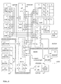
- the microprocessor is used as a control unit 6 for the entire franking machine and is connected to blocks 4, 5, 7 to 11 of the first circuit part 1 via address lines A and data lines D and via address, data and control lines (A, D, S) connected to the second circuit part 14, which is designed as an ASIC.
- the above-mentioned blocks are addressed by the microprocessor in accordance with the memory control signals S s generated in the decoder of the ASIC.
- the function-determining ones - in FIG. 1 shown - blocks of the first circuit part partial or total to at least one physical Component are summarized and others Measures should be taken to prevent tampering difficult by unauthorized persons.
- the Function of these blocks and such measures are for example in the German patent application DE 43 44 476 A1 explained in more detail.
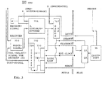
- the circuit part 14, shown in more detail in FIG. 2, for the interface inside the postage meter machine, which is designed in accordance with the type of postage meter machine, has a decoder 300 for providing the memory control signals, an actuator / sensor controller 400, an interrupt controller 600 and a print data controller 700.
- the address lines A0 to A3 and data lines D and control lines S are connected to all blocks 300, 400, 600 and 700. Address lines A13 to A19 are also present on the decoder.
- Decoder 300 provides memory control signals S s for blocks 400, 600 and 700.
- the block 400 for the actuator / sensor control outputs a signal I i on the output side to the block 600 for the interrupt control.
- the block 600 is connected on the output side to the control unit 6 via the lines for the data and control signals I o (FIG. 1).
- the ASIC circuit part 14 is equipped with an input s for connection to the sensors of the base and with an output a for connection to the actuators of the base of the franking machine via a register unit 28 (FIG. 1). More detailed information on the actuators / sensors and on the interrupt control can be found in EP 716 398 A2.
- the register groups of all blocks 300, 400, 600 and 700 can - in a manner not shown - within of the ASIC 14 form its own block 500, which in communication with the other blocks stands.
- a sensor for time-critical data is the encoder 13. On the one hand, this is - in the manner shown in FIG. 1 - directly at the input e of the control unit 6 and on the other hand is connected to the input e of the second circuit part (ASIC) 14.
- the encoder acts on a DMA controller present in the control unit 6.
- the DMA controller reads out a complete stamp image from the pixel memory (RAM) 7 and reads it into the print register (DR) of the print head 16 in print column-wise fashion via the ASIC print data controller 700.
- the encoder 13 acts directly on the print data controller 700 by supplying an external trigger signal for the transfer of the print data for the individual print columns to a second state machine 701.
- the print data controller 700 is in FIG a first variant explained.
- a third State machine 701 is with a transmit shift register 710 and with a test shift register 720 connected to the control of data transfer by means of a signal CLOCKOUT.
- the Send shift register 710 sends that from the DMA controller delivered bytes to the print register (DR) 15.
- a series-parallel conversion takes place here the data for the printhead electronics of the printhead 16.
- the printhead 16 contains for temporary storage the parallel print data register, which with a signal LATCH corresponding to the Encoder signal at input e can be controlled, as well Driver, which is signaled by a STROBE signal from the Control unit 6 can be controlled.
- the drivers control the actual printing elements of the Printhead 16.
- the ASIC 14 can be used in conjunction with the first Circuit part 1 based on a test circuit 702 serial data transfer can be monitored.
- the Test shift register 720 can get data from the print register 15 received serially, which after serial-parallel conversion from the control device 6 can be read via the data line D if necessary can.
- the ASIC 14 can be used in conjunction with the first circuit part 1 due to a local Loop and by means of the test circuit 702 serial data transfer can be tested. Is to provided that the bits of the Send shift register 710 for serial print data Purpose testing via a local loop LOCAL LOOP and into a test shift register by means of a test circuit 702 720 can be read.
- Additional registers can be in register block 500 of the ASIC's 14 can be provided and can be connected with the third state machine 701 more Data, clock or control signals to the printer register 15 and deliver the printhead electronics, see above that the control even when using different Printheads becomes possible.
- FIG. 4 is a block diagram for a second variant of the print data control according to the invention with training as a security module shown.
- the on an expanded printhead hardware connected print data control unit 700 - According to the embodiment shown in Figure 3 expanded to include a second code generator 703, a multiplexer 709, a demultiplexer 725 and a second comparator 723.
- the modification of the extended printhead hardware compared to the print data control unit shown in FIG on the one hand results from a very large number of print data to be transmitted, for example 200 dpi (dot per inch) for one Pressure column.
- Send shift register 710 or the print register DR 15 need to transfer data for a print column be designed. The printing is done column by column preferably on an envelope if the print column data parallel to the printhead STROBE signal is switched to the printhead.
- the predetermined Code via first switch means 34 den Pressure register 15 supplied, which the predetermined Code as activation code serial to the print data control unit 700 transmitted.
- the first switch 34 are preferably field effect transistors or other comparable taxable electronic switches.
- such a version has a Print data controller 700 a third state machine 701 on the input side with a Mode register group 750 for setting the Operating mode and output side with control inputs the transmit shift register 710, a test circuit 702 and the external print register 15 is to be switched on from a first Code generator 32 issued receipt code under Controlled by the third state machine 701 into a test shift register 720.
- the Test shift register 720 is the acknowledgment code can be called up in parallel and the test circuit 702 is according to a set security printer mode trained the serial data transfer between print register 15, print head electronics 30 on the one hand and the transmit shift register 710 on the other hand, to monitor the bits received to monitor for predetermined changes in state.
- an interrupt for Control unit 6 are transmitted to subsequently a print data transfer to the print head trigger.
- the control unit 6 runs automatically without Participation of the control unit 6 (CPU). Thereby the control unit 6 (CPU) is relieved.
- the interface circuit inside the franking machine is equipped with send and receive registers for the storage of data transmitted in parallel Data and with a shift register for that Series / parallel or parallel / series conversion of the from or to the print head via a print register transferred data.
- Print data length information becomes the print head as part of a coded data exchange, the u.a. the length of the print Image in bytes or in a predetermined number contains to pressure columns, transmitted.
- the u.a. the length of the print Image in bytes or in a predetermined number contains to pressure columns, transmitted.
- the aforementioned print data length information from the demultiplexer DEMUX 35 into the monitoring module 36 transmitted for print data length monitoring, before that sent to the printhead
- Print data transmission signal the unencrypted Contains image data.
- the state of activation is a print data length monitoring for the unencrypted image data performed to the Termination of data transmission for the aforementioned to determine the individual print image. Locking the Printhead will be reached when the predetermined print data length information Print data length triggered.
- a method for manipulation-proof print data control after another version works with several generated codes at the same time. It is provided that to carry out the encoded Data exchange code independently of each other are generated to compare the Printhead electronics transmitted codes with a generated first code and a comparison of the codes transmitted to the print data control unit a second code.
- the aforementioned has another version for such a print data controller 700 with training a second code generator for the security module 703 for generating one for everyone Imprint unique unlock codes and one third state machine 701 on the input side with a mode register group 750 for Setting the operating mode and on the output side with Control inputs of the transmit shift register 710, a test circuit 702 and the external print register 15 is connected to one of one emitted first connectable code generator 32 second receipt code under the control of the third state machine 701 into a test shift register 720 to insert.
- the second acknowledgment code is available in parallel before and the test circuit 702 is corresponding a set security printer mode, serial data transfer between print registers 15, printhead electronics 30 on the one hand and the transmit shift register 710, on the other hand, around the received bits to predetermined ones Monitor changes in state. Thus, if necessary an interrupt is transmitted to the control unit 6 in order to subsequently transfer a print data trigger to the printhead. If the Transmission over the DMA channel is started, this runs automatically without the involvement of the control unit 6 (CPU) onwards. This also makes the Control unit 6 (CPU) relieved.
- the print data control unit 700 which the Control unit 6 of pressure monitoring tasks relieve, it is provided that at the parallel Output of test shift register 720 a first Input and at the parallel output of a second Code generator 703 a second input of a digital comparator 723 for checking the second receipt codes is connected, the parallel data bits of the second acknowledgment code with those from the second code generator 703 supplied data bits of a first activation code be compared and if there is a mismatch Error message for the monitoring circuit (723, 600) is transmitted.
- the entrances are preferably of the digital comparator (723) with internal Buffer storage for temporary storage before a Check the code provided. Internally comes again an XOR link is used.
- the control unit CPU 6 is over a DMA channel connected to transmit shift register 710.
- the Transmission of the error message for interrupt control 600 interrupted and instead Agreement signals.
- To report the match becomes a signal J for interrupt control (600) transmitted.
- an interrupt is generated and delivered to the control unit CPU 6, whereby is caused by the control unit CPU 6 Print data to the transmit shift register via the DMA channel 710 are transmitted.
- a multiplexer MUX 709 connected to the second activation code or via the DMA channel transmitted print data in the send shift register Invite 710.
- the printhead electronics 30 has a fourth State machine 31 on the input side with a clock signal CLOCKOUT from the third state machine 701 and from a monitoring module 36 is supplied with an output signal and on the output side with a control input of a first one electronic switch 34, with a control input a second electronic switch 37, with a first code generator 32 and with a Control input of a demultiplexer DEMUX 35 connected is, at a first output of the Demultiplexers DEMUX 35 for parallel data transfer an internal buffer for the printhead DK 16 is connected.
- the parallel Output of the first code generator 32 a first Input and at the second output of the demultiplexer DEMUX 35 a second input of a digital Comparator 33 for checking the activation code is connected, the parallel retrievable data bits of the second activation code with those supplied by the first code generator 32 Data bits of a first acknowledgment code compared an error message if they do not match is transmitted to the monitoring module 36, that the monitoring module 36 otherwise at Agreement is unlocked and that from fourth state machine 31 of the demultiplexer DEMUX 35 for parallel data transmission via its first output to an internal buffer of the monitoring module 36 switched becomes.
- the monitoring module DLC 36 preferably has Counters to act on columns or bytes to carry out a pressure length monitoring.
- the counter DLC 36 generates an output signal to the fourth state machine 31 upon reaching one predetermined print length.
- the fourth state machine 31 acts on the Control input of the second electronic switch 37 to when a predetermined printing length is reached a signal supplied by encoder 13 LATCH from internal buffer of the print head DK 16 switch off, so that no further print data can be printed by the print head DK.
- the fourth State machine 31 the control input of the first electronic switch 34 applied and from first code generator 32 into the print register second receipt code is read, which for Print data control 700 is transmitted.
- the inputs of the digital comparator 33 with internal buffer storage for temporary storage before checking the code.
- this franking machine internal interface circuit to the base a number of serial Interfaces with any expansion options forms, this enables an adaptation to the various franking systems and to each base Franking machine, on the one hand for the purpose of sensor query and for actuator setting, with a non-periodic Query by a microprocessor 6 and with an interrupt controller 600 and on the other hand for a print data controller 700 with operating mode setting and testing options.
- the invention is not based on the present embodiment limited. Rather is a number of variants conceivable, which of the shown Solution also with different types Make use.
Abstract
Description
Die Erfindung betrifft ein Verfahren zur
manipulationssicheren Druckdatensteuerung und eine
frankiermaschineninterne Schnittstellenschaltung
gemäß der im Oberbegriff der Ansprüche 1 und 5
angegebenen Art.The invention relates to a method for
manipulation-proof print data control and a
Interface circuit internal to the franking machine
according to that in the preamble of
Frankiermaschinen weisen mindestens eine Transportvorrichtung, Eingabe-, Speicher- und Anzeigemittel und eine Druckansteuereinheit für eine Druckvorrichtung auf, welche Druckmuster auf einen zu dieser Druckvorrichtung bewegten zu bedruckenden Aufzeichnungsträger druckt. Derartige Druckvorrichtungen, insbesondere für einen elektrothermischen Druck mittels Farbband bzw. Transportvorrichtungen sind mit Aktoren und Sensoren ausgestattet, welche über eine Schaltungsanordnung angesteuert bzw. abgefragt werden (US 4 746 234). Franking machines have at least one transport device, Input, storage and display means and a pressure control unit for a printing device on what print patterns toward you this printing device moved to be printed Record carrier prints. Such printing devices, especially for an electrothermal Printing using an ink ribbon or transport devices are equipped with actuators and sensors, which controlled via a circuit arrangement or are queried (US 4,746,234).
Sensoren, die den Transport des Aufzeichnungsträgers detektieren, lösen beispielsweise den Druckvorgang aus. Andere Sensoren ermitteln die Stellung der Gegendruckrolle bzw. überwachen den laufenden Druckvorgang.Sensors used to transport the record carrier detect, solve, for example Printing process. Other sensors detect that Position of the counter pressure roller or monitor the ongoing printing.
Eine Welle der Transportvorrichtung oder Spule eines relativ zum Aufzeichnungsträger bewegten Farbträgers, der die Farbpartikel überträgt, ist mit einem Encoder gekoppelt, welcher Taktsignale für die Drucksteuerung während des Druckvorganges zur Verfügung stellt. Alle Sensoren bzw. Aktoren sind direkt oder indirekt über eine spezielle Schaltungsanordnung mit der Ansteuereinheit, insbesondere einer Mikroprozessor-Steuereinheit, verbunden.A shaft of the transport device or coil one moved relative to the record carrier Color carrier that transfers the color particles coupled to an encoder, which clock signals for printing control during the printing process provides. All sensors or actuators are directly or indirectly through a special Circuit arrangement with the control unit, in particular a microprocessor control unit, connected.
Für ein Thermotransferdruckverfahren ist bereits aus der DE 38 33 746 A1 eine über eine Ansteuereinheit beaufschlagte Schalteinheit für einen Druckkopf bekannt, der Widerstandselemente enthält. Eine selektive Ansteuerung mit Vorheizung der Widerstandselemente dient zur Verringerung der Heizleistung beim Drucken. Zum Ansteuern eines Druckkopfes wird Energie für die einzelnen Pixel des Druckbildes definiert bereitgestellt und ein Druckmuster auf einen zum Farbband relativ bewegten zu bedruckenden Aufzeichnungsträgers gedruckt, indem das Farbband die Farbpartikel aus der Farbschicht bei Erhitzung des zugehörigen Heizwiderstandes im Druckkopf auf den Aufzeichnungsträger überträgt.For a thermal transfer printing process is already from DE 38 33 746 A1 via a control unit actuated switching unit for one Known printhead that contains resistance elements. A selective control with preheating the Resistance elements serves to reduce the Heating power when printing. To control one Printhead becomes energy for each pixel of the printed image provided and a Print pattern on a relative to the ribbon printed on the recording medium to be printed, by removing the ribbon from the paint layer when the associated heating resistor is heated in the print head on the record carrier transmits.
Zum Frankieren von Postgut sind auch Tintenstrahldrucker geeignet. Entsprechend des verwendeten Druckprinzips muß die Schaltungsanordnung an die erforderlichen Aktoren und Sensoren angepaßt werden. Inkjet printers are also used to frank mail suitable. According to the used Printing principle must the circuit arrangement to the required actuators and sensors adapted become.
Aus dem EP 465 236 A2 ist ein ASIC bekannt, welches eine Schaltung zur Drucksteuerung, zur Motorsteuerung und zur Abrechnung umfaßt. Die Schaltung zur Drucksteuerung umfaßt einen Speicher für feste und einen anderen für variable Daten, welche mit den festen Daten überlagert werden. Ein Motorcontroller ist für ein Aktuieren eines Motorantriebes in Abhängigkeit von der Poststückzuführung vorgesehen. Ein Tachosignale liefernder Sensor steht über den Motorcontroller mit der Drucksteuerung in Verbindung. Ein Vorteil ist zweifellos die hohe Manipulationssicherheit resultierend allein bereits aus der eingeschränkten Anzahl an Ansatzpunkten für eine Manipulation, aufgrund der Verwendung eines einzigen ASIC. Ein Nachteil der Verwendung eines einzigen ASICs ist die fehlende Verwendbarkeit für unterschiedliche Frankiermaschinen, welche einen unterschiedlichen Drucksteuermodul entsprechend eines realisierten Frankiermaschinensystem bzw. Poststraße aufweisen.An ASIC is known from EP 465 236 A2, which a circuit for pressure control, for engine control and includes for billing. The circuit for pressure control includes a memory for fixed and another for variable data, which with overlay the fixed data. An engine controller is for actuating a motor drive provided depending on the mailpiece feed. A sensor delivering speed signals is standing via the motor controller with the pressure control in Connection. The high is undoubtedly an advantage Tampering security alone results from the limited number of starting points for a manipulation due to the use of a single ASIC. One disadvantage of using one The only ASIC is the lack of usability for different franking machines, which one different pressure control module accordingly a realized franking machine system or Show Poststrasse.
Sollen aber verschiedene Typen an Frankiermaschinen produziert werden dann müssen eine Vielzahl an Schaltkreisen (ASIC's oder/ und andere Bauelemente) vorgesehen werden. Gerade die Vielzahl an Bauelementen und Schaltkreisen bietet dann Ansatzpunkte für eine Manipulation, wenn kein alternativer Aufwand getrieben und ein Sicherheitsgehäuse eingesetzt wird. Die Frankiermaschinentypen unterscheiden sich in Form und Ausstattung entsprechend des zu bearbeitenden Postaufkommens und somit auch bezüglich einer unterschiedlichen Anzahl an Sensoren und Aktoren.But should different types of franking machines then a variety of must be produced Circuits (ASIC's or / and other components) be provided. Especially the large number of components and circuits then offer starting points for manipulation, if no alternative Effort driven and a security case is used. Differentiate between franking machine types accordingly in shape and equipment of the mail volume to be processed and thus also regarding a different number Sensors and actuators.
Aus der EP 231 452 A2 ist das periodische Abfragen von Sensoren entsprechend einer Softwareroutine einer Zentralverarbeitungseinheit (CPU), vorzugsweise eines Mikroprozessors, bekannt. This is periodic polling from EP 231 452 A2 of sensors according to a software routine a central processing unit (CPU), preferably a microprocessor known.
Der Nachteil dieser Lösung besteht in einer hohen Rechenzeit bedingt durch das periodische Abtasten der Sensoren. Dieser Nachteil wird noch vergrößert, wenn es sich um eine besonders zeitkritische Abfrage handelt. Um möglichst schnell auf eine Zustandsänderung reagieren zu können, muß die Abfragefrequenz hoch gewählt werden. Somit verbringt der Mikroprozessor einen großen Anteil seiner Rechenzeit mit der Abfrage.The disadvantage of this solution is a high one Computing time due to periodic sampling of the sensors. This disadvantage is exacerbated if it is a particularly time-critical Query. To get to one as quickly as possible To be able to react to a change in state Polling frequency can be selected high. Consequently the microprocessor spends a large proportion its computing time with the query.
In der US 5,267,172 ist auch schon eine serielle Schnittstelle in einer Frankiermaschine vorgeschlagen worden, welche zwischen einem Mikroprozessor und einem ASIC angeordnet ist und auf welcher Adresse, Kommando und Daten seriell zum ASIC übertragen werden. Nachteilig ist, daß zeitkritische Abfragen nicht realisiert werden können und keine selbsttätige Arbeit der Schnittstelle vorliegt, was Rechenzeit im Mikroprozessor bindet.In US 5,267,172 there is already a serial Interface proposed in a franking machine been between a microprocessor and an ASIC is arranged and on which Transfer address, command and data serially to the ASIC become. The disadvantage is that time-critical Queries cannot be realized and none automatic work of the interface is what Computing time in the microprocessor binds.
Der zuletzt genannte Nachteil trifft ebenfalls auf ein aus der US 5,199,105 bekanntes Datenverarbeitungssystem zu. Für einen universellen asynchronen Empfänger/Sender-Baustein wird dort ein erstes Schieberegister zum Ausgeben der Daten und ein zweites Schieberegister zum Einlesen der Daten sowie ein programmierbares Vergleichsregister vorgeschlagen, um Interrupt auszulösen, wenn ein bestimmtes Datenbyte über den seriellen Kanal empfangen wird.The latter disadvantage also applies a data processing system known from US 5,199,105 to. For a universal asynchronous receiver / transmitter module is there first shift register for outputting the data and a second shift register for reading the data as well as a programmable comparison register proposed, to trigger interrupt when a specific data byte over the serial channel Will be received.
Aufgabe ist es, ein Verfahren und eine frankiermaschineninterne Schnittstellenschaltung zu entwickeln, welche die Nachteile des Standes der Technik vermeidet und für eine Vielzahl an Frankiermaschinenvarianten kostengünstig realisierbar ist, ohne dabei die Manipulationssicherheit zu vermindern. The task is to create a procedure and an internal franking machine To develop interface circuitry which have the disadvantages of the prior art Technology avoids and for a variety of franking machine variants realizable at low cost is without manipulation security Reduce.
Eine Unteraufgabe besteht in der Entwicklung einer Druckdatensteuerung, durch die weniger Rechenzeit der CPU gebunden wird und dennoch die Funktions-bzw. Manipulationssicherheit gewahrt bleibt.A subtask is to develop one Print data control through less computing time the CPU is bound and the function or. Manipulation security is maintained.
Die Aufgabe wird mit den Merkmalen der Ansprüche 1
und 5 gelöst.The object is achieved with the features of
Die Erfindung beruht auf der Überlegung, die Anpassungsfähigkeit der elektronischen Steuerung an verschiedene Frankiermaschinentypen durch eine frankiermaschineninterne Schnittstellenschaltung zu verbessern.The invention is based on the consideration that Adaptability of the electronic control different franking machine types by one Interface circuit internal to the franking machine improve.
Innerhalb eines Sicherheitsgehäuses ist ein
Mikroprozessor eines ersten Schaltungsteils, in dem
nur sicherheitsrelevante Daten verarbeitet werden,
mit einem erfindungsgemäßen zweiten Schaltungsteil
verbunden, in welchem die übrigen Daten für jeweils
den entsprechenden Typ von Frankiermaschine
gehändelt werden. Dieser zweite Schaltungsteil
bildet eine frankiermaschineninterne Schnittstelle
zum ersten Schaltungsteil.
In vorteilhafter Weise ist die frankiermaschineninterne
Schnittstellenschaltung als systemspezifisches
ASIC ausgeführt.Within a security housing, a microprocessor of a first circuit part, in which only security-relevant data are processed, is connected to a second circuit part according to the invention, in which the remaining data are traded for the respective type of franking machine. This second circuit part forms an internal franking machine interface to the first circuit part.
The internal interface franking machine is advantageously designed as a system-specific ASIC.
Es wird vorausgesetzt, daß zur Ansteuerung eines elektronischen Druckkopfes und der Aktoren bzw. Sensorabfrage der Mikroprozessor des ersten Schaltungsteils auf den zweiten Schaltungsteil zugreift. Dabei werden vom Mikroprozessor nichtperiodisch Daten abgefragt bzw. an diesen übermittelt.It is assumed that to control a electronic printhead and the actuators or Sensor query the microprocessor of the first Circuit part on the second circuit part accesses. The microprocessor non-periodically queried or at data transmitted.
Der Schaltungsteil für sicherheitsrelevante Daten ist für alle Frankiermaschinetypen gleich ausgebildet. Der zweite Schaltungsteil (ASIC) für die übrigen Daten ist entsprechend dem Frankiermaschinentyp als interne Schnittstelle zum ersten Schaltungsteil ausgebildet.The circuit part for safety-relevant data is the same for all franking machine types educated. The second circuit part (ASIC) for the rest of the data is according to the type of franking machine as an internal interface to the first Circuit part formed.
Der zweite Schaltungsteil (ASIC) ist die frankiermaschineninterne Schnittstellenschaltung. Letztere weist eine Druckdatensteuerung auf. Zur Schaffung der Druckdatensteuerung gemäß der Subaufgabe ist die frankiermaschineninterne Schnittstellenschaltung mit Sende- und Empfangsregistern für die Speicherung parallel übertragener Daten und mit einem Schieberegister für die Serien/Parallel- bzw. Parallel/Serienwandlung der vom bzw. zum Druckkopf über ein Druckregister übertragenen Daten, ausgerüstet.The second circuit part (ASIC) is the internal franking machine Interface circuit. The latter has a print data controller. For Creation of print data control according to the The sub-task is the internal franking machine Interface circuit with send and receive registers for the storage of data transmitted in parallel Data and with a shift register for that Series / parallel or parallel / series conversion of the from or to the print head via a print register transmitted data, equipped.
Aufgrund einer geringen Anzahl an Leitungen zur Base gelingt es, eine kostengünstige Lösung für eine Meter/ Base-Trennung zu schaffen.Due to a small number of lines for Base manages to be an affordable solution for to create a meter / base separation.
Die Druckdatensteuerung wird erfindungsgemäß zum Sicherheitsmodul erweitert und bietet neben der angestrebten Entlastung der Steuereinheit CPU außerdem eine höhere Manipulationssicherheit vor betrügerischer Benutzung des Druckkopfes in Verbindung mit einer speziellen Druckkopfelektronik. Erfindungsgemäß wird in je einem Codegenerator einer Einheit, d.h. in der Druckkopfelektronik und im Sicherheitsmodul, unabhängig voneinander ein Code erzeugt und jeweils zur anderen Einheit übertragen. Vergleicher prüfen den empfangenen Freischalt- bzw. Quittungscode mit dem erwarteten Code. Bei Korrektheit wird der Druckkopf für ein einzelnes Druckbild freigeschaltet. Das zu druckende Bild wird dann in "Klarschrift" (unverschlüsselt) übertragen. Nach Beendigung der Datenübertragung ist der Druckkopf automatisch wieder gesperrt und muß mit Hilfe eines weiteren kodierten Datenaustausches freigeschaltet werden. Für jedes Druckbild wird ein neuer kodierter Datensatz zur Freischaltung bzw. Quittierung erzeugt damit eine Aufzeichnung des Freischaltevorganges nicht wiederverwendet werden kann.According to the invention, the print data control becomes Security module expanded and offers in addition to the targeted Relief of the control unit CPU as well a higher security against manipulation against fraudulent Using the printhead in conjunction with special printhead electronics. According to the invention is one in each code generator Unity, i.e. in printhead electronics and Security module, independently of each other a code generated and transferred to the other unit. Comparators check the received activation or Acknowledgment code with the expected code. If correct becomes the printhead for a single print image unlocked. The image to be printed is then in "Plain text" (unencrypted) transmitted. To The print head is the end of the data transfer automatically locked again and must be with the help of a further coded data exchange unlocked become. A new code is encoded for each print image Data record for activation or acknowledgment creates a record of the activation process cannot be reused.
Erfindungsgemäß ist in einer weiteren Variante vorgesehen, daß die Druckdatensteuerung einen dritten Zustandsautomaten aufweist, der eingangsseitig mit einer Modusregistergruppe zur Einstellung der Betriebsart und ausgangsseitig mit Steuereingängen des Sende-Schieberegisters, einer Testschaltung und eines Druckregisters verbunden ist, um einen von einem ersten anschaltbarem Codegenerator abgegebenen zweiten Quittungscode unter Steuerung durch den dritten Zustandsautomaten in ein Test-Schieberegister einzuschieben, wobei im Test-Schieberegister der zweite Quittungscode parallel abrufbar vorliegt und wobei die Testschaltung entsprechend eines eingestellten Sicherheitsdruckermodus ausgebildet ist, den seriellen Datentransfer zwischen Druckregister Druckkopfelektronik einerseits und dem Sende-Schieberegister andererseits zu überwachen, um die empfangenen Bits auf vorbestimmte Zustandsveränderung zu überwachen, um ggf. einen Interrupt zur Steuereinheit und um damit eine DMA-gesteuerte Druckdatenübertragung zum Druckkopf auszulösen.Another variant is according to the invention provided that the print data control a has third state machine, the input side with a mode register group for setting the operating mode and on the output side with Control inputs of the transmit shift register, one Test circuit and a pressure register connected is to one of a first connectable code generator submitted second receipt code under Controlled by the third state machine in insert a test shift register, where in Test shift register the second receipt code available in parallel and the test circuit according to a set security printer mode is trained, the serial Data transfer between print register printhead electronics on the one hand and the send shift register on the other hand, to monitor the bits received to monitor for predetermined changes in state, around an interrupt to the control unit if necessary and around thus a DMA-controlled print data transfer to Trigger printhead.
Vorteilhafte Weiterbildungen der Erfindung sind in den Unteransprüchen gekennzeichnet bzw. werden nachstehend zusammen mit der Beschreibung der bevorzugten Ausführung der Erfindung anhand der Figuren näher dargestellt. Es zeigen:
Figur 1,- Blockschaltbild der Schaltungsanordnung für Meter und Base,
Figur 2,- Blockschaltbild der frankiermaschineninternen Schnittstellenschaltung,
Figur 3,- Blockschaltbild für eine erste Variante der erfindungsgemäßen Druckdatensteuerung mit Testschaltung,
Figur 4,- Blockschaltbild für eine zweite Variante der erfindungsgemäßen Druckdatensteuerung mit Sicherheitsmodul.
- Figure 1,
- Block diagram of the circuit arrangement for meter and base,
- Figure 2,
- Block diagram of the franking machine internal interface circuit,
- Figure 3,
- Block diagram for a first variant of the print data control according to the invention with test circuit,
- Figure 4,
- Block diagram for a second variant of the print data control according to the invention with a safety module.
Die Figur 1 zeigt ein Blockschaltbild einer
Schaltungsanordnung für eine Frankiermaschine. Die
Schaltungsanordnung läßt sich zwei Teilen, nämlich
Meter und Base zuordnen, wobei die Base mindestens
die Motoren und andere Aktoren, Sensoren sowie den
Druckkopf nebst zugehöriger Ansteuerelektronik
enthält. Das Meter enthält als ersten Schaltungsteil
die eigentliche Steuerung, die mit einem
Ein/Ausgabe-Modul 4 und insbesondere mit einem
zweiten Schaltungsteil, der erfindungsgemäßen
frankiermaschineninternen Schnittstellenschaltung
verbunden ist, welche vorteilhaft als ASIC 14
ausgebildet sein kann. Die Steuerung umfaßt in
bekannter Weise einen Uhr/Datums-Block 8, einen
Charakterspeicher 9, einen Kostenstellenspeicher
10, einen nichtflüchtigen Speicher 5, Programmspeicher
11 und Arbeitsspeicher 7, welche mit einem
Mikroprozessor in kommunikativer Verbindung stehen.1 shows a block diagram of a
Circuit arrangement for a franking machine. The
Circuit arrangement can be divided into two parts, namely
Assign meter and base, the base at least
the motors and other actuators, sensors and the
Printhead with associated control electronics
contains. The meter contains the first circuit part
the actual control that comes with a
Input /
Im Uhr/Datums-Block 8 werden Zeitdaten und das
Datum auch bei abgeschalteter Frankiermaschine
generiert. Der Ein/Ausgabe-Modul 4 stellt beispielsweise
über eine RS 232-Schnittstelle eine
Verbindung zum Modem 23 und ggf. zur Waage 22 her.
Letztere können Bestandteil der Base sein. Außerdem
sind am Modul 4 der Displaycontroller 3 und die
Tastatur 2 angeschlossen.In the clock /
Die Eingabedaten werden im nichtflüchtigen Speicher
(NVM) 5 so gespeichert, daß die letzte Einstellung
vor einem Ausschalten der Frankiermaschine erhalten
bleibt. Im Programmspeicher 11 sind das Betriebsprogramm
und Fixdaten, beispielsweise für ein
Werbeklischee, gespeichert. Im Kostenstellenspeicher
10 werden die aktuellen Abrechnungsdaten
kostenstellenabhängig vor jedem Druck nichtflüchtig
gespeichert.The input data is stored in the non-volatile memory
(NVM) 5 saved so that the last setting
received before the franking machine was switched off
remains. The operating program is in the
Im Charakterspeicher 9 ist der entsprechende
Zeichensatz vorhanden. Gemäß den Eingaben werden
entsprechende Zeichen als Pixeldaten im
Pixelspeicher 7 gespeichert.The corresponding is in the
Der Mikroprozessor wird als Steuereinheit 6 für die
gesamte Frankiermaschine eingesetzt und ist über
Adreßleitungen A und Datenleitungen D mit den
Blöcken 4, 5, 7 bis 11 des ersten Schaltungsteils 1
und über Adreß-, Daten- und Steuerleitungen (A,D,S)
mit dem zweiten Schaltungsteil 14 verbunden,
welcher als ASIC ausgebildet ist. Entsprechend der
im Decoder des ASIC's generierten SpeichersteuerSignale
Ss werden vom Mikroprozessor die vorgenannten
Blöcke adressiert.The microprocessor is used as a
Dabei können die funktionsbestimmenden - in Figur 1 gezeigten - Blöcke des ersten Schaltungsteils partiell oder total zu mindestens einem physikalischen Bauelement zusammengefaßt werden und weitere Maßnahmen vorgesehen sein, um eine Manipulation durch unberechtigte Personen zu erschweren. Die Funktion dieser Blöcke und derartige Maßnahmen sind beispielsweise in der deutschen Patentanmeldung DE 43 44 476 A1 näher erläutert.The function-determining ones - in FIG. 1 shown - blocks of the first circuit part partial or total to at least one physical Component are summarized and others Measures should be taken to prevent tampering difficult by unauthorized persons. The Function of these blocks and such measures are for example in the German patent application DE 43 44 476 A1 explained in more detail.
Die Erfindung wird im nachfolgenden Ausführungsbeispiel nebst Figuren 2 bis 4 näher erläutert.The invention is illustrated in the following embodiment together with Figures 2 to 4 explained in more detail.
Der - in der Figur 2 näher dargestellte-Schaltungsteil
14 für die frankiermaschineninterne
Schnittstelle, der entsprechend dem Frankiermaschinentyp
ausgebildet ist, weist einen Decoder 300 zur
Bereitstellung der Speichersteuersignale, eine
Aktoren/Sensoren-Steuerung 400, einen Interruptcontroller
600 und eine Druckdatensteuerung 700
auf. Die Adressenleitungen A0 bis A3 und Datenleitungen
D sowie Steuerleitungen S liegen an allen
Blöcken 300, 400, 600 und 700 an. Am Decoder liegen
auch Adressenleitungen A13 bis A19 an. Der Decoder
300 stellt Speichersteuersignale Ss für die Blöcke
400, 600 und 700 zur Verfügung. Der Block 400 für
die Aktoren/Sensoren-Steuerung gibt ausgangsseitig
ein Signal Ii an den Block 600 für die Interruptsteuerung
ab. Der Block 600 steht ausgangsseitig
über die Leitungen für die Daten- und Steuersignale
Io mit der Steuereinheit 6 in Verbindung (Fig.1).
Das als ASIC ausgebildete Schaltungsteil 14 ist mit
einem Eingang s für den Anschluß an die Sensoren
der Base und mit einem Ausgang a für den Anschluß
an die Aktoren der Base der Frankiermaschine über
eine Registereinheit 28 ausgestattet (Fig.1).
Detailiertere Angaben zur Aktoren/Sensoren- und zur
Interrup-Steuerung sind dem EP 716 398 A2
entnehmbar.The
Die Registergruppen aller Blöcke 300, 400, 600 und
700 können - in nicht gezeigter Weise - innerhalb
des ASICs 14 einen eigenen Block 500 bilden, der
mit den anderen Blöcken in Kommunikationsverbindung
steht.The register groups of all
Ein Sensor für zeitkritische Daten ist der Encoder
13. Dieser liegt einerseits - in aus der Figur 1
ersichtlichen Weise - direkt am Eingang e der
Steuereinheit 6 an und ist andererseits am Eingang
e des zweiten Schaltungsteils (ASIC) 14 angeschlossen.
Der Encoder wirkt auf einen in der
Steuereinheit 6 vorhandenen DMA-Controller.
Der DMA-Controller liest ein komplettes Stempelbild
aus dem Pixelspeicher (RAM) 7 aus und über die
ASIC-Druckdatensteuerung 700 in das Druckregister
(DR) des Druckkopfes 16 druckspaltenweise ein. Der
Encoder 13 wirkt direkt auf die Druckdatensteuerung
700, indem er ein externes Triggersignal für die
Übertragung der Druckdaten für die einzelnen
Druckspalten an einen zweiten Zustandsautomaten 701
liefert.A sensor for time-critical data is the
The DMA controller reads out a complete stamp image from the pixel memory (RAM) 7 and reads it into the print register (DR) of the
Die Druckdatensteuerung 700 ist in der Figur 3 für
eine erste Variante näher erläutert. Eine dritte
Zustandsmaschine 701 ist mit einem Sendeschieberegister
710 und mit einem Testschieberegister 720
verbunden, um die Steuerung des Datentransfers
mittels eines Signals CLOCKOUT zu übernehmen. Das
Sendeschieberegister 710 sendet die von dem DMA-Controller
gelieferten Bytes an das Druckregister
(DR) 15. Hier erfolgt eine Serien-Parallel-Wandlung
der Daten für die Druckkopfelektronik des Druckkopfes
16. Der Druckkopf 16 enthält zur Zwischenspeicherung
der parallelen Druckdaten Register,
welche mit einem Signal LATCH entsprechend dem
Encodersignal am Eingang e gesteuert werden, sowie
Treiber, welche durch ein Signal STROBE von der
Steuereinheit 6 gesteuert werden. Die Treiber
steuern die eigentlichen Druckelemente des
Druckkopfes 16.The
Im ASIC 14 kann in Verbindung mit dem ersten
Schaltungsteil 1 aufgrund einer Testschaltung 702
der serielle Datentransfer überwacht werden. Das
Testschieberegister 720 kann Daten vom Druckregister
15 seriell empfangen, welche nach Serien-Parallel-Umwandlung
von der Steuereinrichtung 6
über die Datenleitung D bei Bedarf gelesen werden
können.The
Außerdem kann im ASIC 14 in Verbindung mit dem
ersten Schaltungsteil 1 aufgrund einer lokalen
Schleife und mittels der Testschaltung 702 der
serielle Datentransfer getestet werden. Dazu ist
vorgesehen, daß in den Druckpausen die Bits des
Sendeschieberegisters 710 für serielle Druckdaten
zweck Testung über eine lokale Schleife LOCAL LOOP
und mittels einer Testschaltung 702 in ein Test-schieberegister
720 eingelesen werden.In addition, the
Durch spezielle - in der Figur 3 gezeigte-Modusregister
750 kann von der Steuereinheit 6 über
die Datenleitung D die Betriebsart eingestellt
werden. Somit kann die Anzahl der Bytes, die Art
des Transfers (mit oder ohne Byte Counter) und die
Taktrate des Schiebetaktes vorbestimmt werden.Through special mode registers shown in Figure 3
750 can from the
Weitere Register können im Registerblock 500 des
ASIC's 14 vorgesehen sein und können in Verbindung
mit dem dritten Zustandsautomaten 701 weitere
Daten, Takt- oder Steuersignale an das Druckerregister
15 und die Druckkopfelektronik abgeben, so
daß die Ansteuerung auch beim Einsatz verschiedener
Druckköpfe möglich wird.Additional registers can be in register block 500 of the
ASIC's 14 can be provided and can be connected
with the
Das Problem bezüglich der Manipulationssicherheit
eines extern vom Meter in der Base angeordneten
Druckkopfes wurde mit Hilfe einer speziellen Druckkopfelektronik
und mit speziellen Schaltungsmaßnahmen
in der Druckdatensteuereinheit 700 gelöst,
welche die Steuereinheit 6 von Drucküberwachungsaufgaben
entlasten. Dabei wird eine Freischaltung
für ein einzelnes Druckbild realisiert. Freischaltsignale
bzw. Überwachungsdaten können zwar auch
separat übermittelt werden, was aber aufwendiger
wäre, als bei einer seriellen Übermittlung.The problem of tamper security
one external to the meter in the base
Printhead was created using special printhead electronics
and with special circuit measures
solved in the print
In der Figur 4 ist ein Blockschaltbild für eine
zweite Variante der erfindungsgemäßen Druckdaten-steuerung
mit einer Ausbildung zum Sicherheitsmodul
dargestellt. Die an einer erweiterten Druckkopfhardware
angeschlossene Druckdatensteuereinheit 700
- gemäß der in der Figur 3 gezeigten Ausführung-wird
erweitert, um einen zweiten Codegenerator 703,
einen Multiplexer 709, einen Demultiplexer 725 und
einen zweiten Komparator 723. Zusätzlich wird die-in
der Figur 3 gezeigte - Druckkopfhardware um eine
Druckkopfelektronik 30 erweitert, welche einen
ersten Codegenerator 32, einen Demultiplexer 35,
einen ersten Komparator 33, einen Überwachungsbaustein
36 zur Druckdatenlängenüberwachung für ein
einzelnes freigeschaltetes Druckbild, erste und
zweite Schaltermittel 34, 37 und einen vierten
Zustandsautomaten 31 einschließt.FIG. 4 is a block diagram for a
second variant of the print data control according to the invention
with training as a security module
shown. The on an expanded printhead hardware
connected print data control unit 700
- According to the embodiment shown in Figure 3
expanded to include a
Die Modifikation der erweiterten Druckkopfhardware
gegenüber in der Figur 3 gezeigten Druckdatensteuereinheit
ergibt sich einerseits aus einer sehr
großen Anzahl von zu übermittelnden Druckdaten,
beispielsweise 200 dpi (dot per inch) für eine
Druckspalte. Auch das in Figur 3 gezeigte
Sendeschieberegister 710 bzw. das Druckregister DR
15 müssen zur Datenübermittlung für eine Druckspalte
ausgelegt sein. Der Druck erfolgt spaltenweise
vorzugsweise auf ein Kuvert, wenn die Druckspaltendaten
parallel am Druckkopf anliegen ein
STROBE-Signal auf den Druckkopf geschaltet wird.The modification of the extended printhead hardware
compared to the print data control unit shown in FIG
on the one hand results from a very
large number of print data to be transmitted,
for example 200 dpi (dot per inch) for one
Pressure column. Also the one shown in Figure 3
Andererseits wird mit der speziellen Druckkopfelektronik
einem Bedürfnis nach Manipulationssicherheit
entsprochen. Vor Druckbeginn wird von
der erfindungsgemäß zum Sicherheitsmodul ausbildeten
Druckdatensteuerung im Meter zur speziellen
Druckkopfelektronik in der Base ein Freischaltcode
übermittelt. Unter Steuerung durch den vierten
Zustandsautomaten 31 wird der nach einer
Serien/Parallel-Wandlung im Druckregister 15
zwischengespeicherte Freischaltcode über einen
Demultiplexer 35 an einen ersten Komparator 33
angelegt. Von dem ersten Codegenerator 32 wird
unter Steuerung durch den vierten Zustandsautomaten
31 ein vorbestimmter Code erzeugt und dem ersten
Komparator 33 zugeführt, welcher einen Vergleich
durchführt. Bei einem positiven Vergleich wird ein
Freischaltsignal einem Überwachungsbaustein 36 zur
Druckdatenlängenüberwachung für ein einzelnes
freigeschaltetes Druckbild beaufschlagt. Anderenfalls
bleibt der Druckkopf gesperrt. Gleichzeitig
mit der vorgenannten Freischaltung wird der vorbestimmte
Code über erste Schaltermittel 34 den
Druckregister 15 zugeführt, welches den vorbestimmten
Code als Freischaltcode seriell zur Druckdatensteuereinheit
700 übermittelt. Als erste Schaltermittel
34 eignen sich vorzugsweise Feldeffekttransistoren
oder andere vergleichbare steuerbare
elektronische Schalter.On the other hand, with the special printhead electronics
a need for security against manipulation
met. Before printing begins
the trained according to the invention to the security module
Print data control in the meter for special
Printhead electronics in the base an activation code
transmitted. Under the control of the
Erfindungsgemäß weist eine solche Version einer
Druckdaten-Steuerung 700 einen dritten Zustandsautomaten
701 auf, der eingangsseitig mit einer
Modusregistergruppe 750 zur Einstellung der
Betriebsart und ausgangsseitig mit Steuereingängen
des Sende-Schieberegisters 710, einer Testschaltung
702 und des externen Druckregisters 15 verbunden
ist, um einen von einem ersten anschaltbarem
Codegenerator 32 abgegebenen Quittungscode unter
Steuerung durch den dritten Zustandsautomaten 701
in ein Test-Schieberegister 720 einzuschieben. Im
Test-Schieberegister 720 liegt der Quittungscode
parallel abrufbar vor und die Testschaltung 702 ist
entsprechend eines eingestellten Sicherheitsdruckermodus
ausgebildet, den seriellen Datentransfer
zwischen Druckregister 15, Druckkopfelektronik
30 einerseits und dem Sende-Schieberegister 710
andererseits zu überwachen, um die empfangenen Bits
auf vorbestimmte Zustandsveränderung zu überwachen.
Durch den zweiten Komparator 723 und die Interruptsteuerung
600 wird eine Überwachungsschaltung
gebildet. Ein Eingang eines - in der Figur 4 nicht
gezeigten - Prioritätsencoders wird über ein-nicht
gezeigtes - D-Flip-Flop mit dem vom zweiten
Komparator 723 ausgangsseitig abgegebenen Signal J
beaufschlagt, welches eine Übereinstimmung
signalisiert. Bei Übereinstimmung wird von der
Interruptsteuerung 600 ein Interrupt generiert.According to the invention, such a version has a
Print data controller 700 a
Somit kann gegebenenfalls ein Interrupt zur
Steuereinheit 6 übertragen werden, um damit anschließend
eine Druckdatenübertragung zum Druckkopf
auszulösen. Wenn die Übertragung über den DMA-Kanal
gestartet wird, läuft diese selbsttätig ohne
Mitwirkung der Steuereinheit 6 (CPU) ab. Dadurch
wird die Steuereinheit 6 (CPU) entlastet.Thus, if necessary, an interrupt for
Die frankiermaschineninterne Schnittstellenschaltung ist ausgerüstet mit Sende- und Empfangsregistern für die Speicherung parallel übertragener Daten und mit einem Schieberegister für die Serien/Parallel- bzw. Parallel/Serienwandlung der vom bzw. zum Druckkopf über ein Druckregister übertragenen Daten.The interface circuit inside the franking machine is equipped with send and receive registers for the storage of data transmitted in parallel Data and with a shift register for that Series / parallel or parallel / series conversion of the from or to the print head via a print register transferred data.
Das Verfahren zur manipulationssicheren Druckdaten-steuerung
ist gekennzeichnet durch die Schritte:
Der Druckkopf wird nach dem Überprüfen des
empfangenen Freischaltcodes für genau einen Abdruck
freigeschaltet. Zum Druckkopf wird eine Druckdatenlängeninformation
im Rahmen eines codierten Datenaustausches,
der u.a. die Länge des zu druckenden
Bildes in Byte oder in einer vorbestimmten Anzahl
an Druckspalten enthält, übermittelt. Vorzugsweise
wird die vorgenannte Druckdatenlängeninformation
vom Demultiplexer DEMUX 35 in den Überwachungsbaustein
36 zur Druckdatenlängenüberwachung übermittelt,
bevor das zum Druckkopf übermittelte
Druckdatenübertragungssignal die unverschlüsselten
Bilddaten enthält. Im Zustand der Freischaltung
wird eine Druckdatenlängenüberwachung für die
unverschlüsselten Bilddaten durchgeführt, um die
Beendigung der Datenübertragung für vorgenanntes
einzelnes Druckbild zu ermitteln. Das Sperren des
Druckkopfes wird dabei ab Erreichung der durch die
vorgenannte Druckdatenlängeninformation vorgegebene
Druckdatenlänge ausgelöst.After checking the
Unlock codes received for exactly one impression
unlocked. Print data length information becomes the print head
as part of a coded data exchange,
the u.a. the length of the print
Image in bytes or in a predetermined number
contains to pressure columns, transmitted. Preferably
becomes the aforementioned print data length information
from the
Ein Verfahren zur manipulationssicheren Druckdaten-steuerung, nach einer anderen Version arbeitet mit mehreren erzeugten Codes gleichzeitig. Es ist vorgesehen, daß zur Durchführung des kodierten Datenaustausches Code unabhängig von einander erzeugt werden, um einen Vergleich des zur Druckkopfelektronik übermittelten Codes mit einem erzeugten ersten Code und um einen Vergleich des zur Druckdatensteuereinheit übermittelten Codes mit einem zweiten Code durchzuführen. A method for manipulation-proof print data control, after another version works with several generated codes at the same time. It is provided that to carry out the encoded Data exchange code independently of each other are generated to compare the Printhead electronics transmitted codes with a generated first code and a comparison of the codes transmitted to the print data control unit a second code.
Erfindungsgemäß weist vorgenannte andere Version
für eine solche Druckdaten-Steuerung 700 mit Ausbildung
zum Sicherheitsmodul einen zweiten Codegenerator
703 für die Generierung eines für jeden
Abdruck einzigartigen Freischaltcodes und einen
dritten Zustandsautomaten 701 auf, der eingangsseitig
mit einer Modusregistergruppe 750 zur
Einstellung der Betriebsart und ausgangsseitig mit
Steuereingängen des Sende-Schieberegisters 710,
einer Testschaltung 702 und des externen Druckregisters
15 verbunden ist, um einen von einem
ersten anschaltbarem Codegenerator 32 abgegebenen
zweiten Quittungscode unter Steuerung durch den
dritten Zustandsautomaten 701 in ein Test-Schieberegister
720 einzuschieben. Im Test-Schieberegister
720 liegt der zweite Quittungscode parallel abrufbar
vor und die Testschaltung 702 ist entsprechend
eines eingestellten Sicherheitsdruckermodus ausgebildet,
den seriellen Datentransfer zwischen Druckregister
15, Druckkopfelektronik 30 einerseits und
dem Sende-Schieberegister 710 andererseits zu überwachen,
um die empfangenen Bits auf vorbestimmte
Zustandsveränderung zu überwachen. Somit kann gegebenenfalls
ein Interrupt zur Steuereinheit 6 übertragen
werden, um damit anschließend eine Druckdatenübertragung
zum Druckkopf auszulösen. Wenn die
Übertragung über den DMA-Kanal gestartet wird,
läuft diese selbsttätig ohne Mitwirkung der Steuereinheit
6 (CPU) ab. Dadurch wird ebenfalls die
Steuereinheit 6 (CPU) entlastet.According to the invention, the aforementioned has another version
for such a
In der Druckdatensteuereinheit 700, welche die
Steuereinheit 6 von Drucküberwachungsaufgaben
entlasten, ist vorgesehen, daß am parallelem
Ausgang des Test-Schieberegister 720 ein erster
Eingang und am parallelem Ausgang eines zweiten
Codegenerators 703 ein zweiter Eingang eines
digitalen Komparators 723 für die Überprüfung des
zweiten Quittungscodes angeschlossen ist, wobei die
parallel abrufbaren Daten-Bits des zweiten Quittungscodes
mit den vom zweiten Codegenerator 703
gelieferten Daten-Bits eines ersten Freischaltcodes
verglichen werden und bei Nichtübereinstimmung eine
Fehlermeldung zur Überwachungsschaltung (723, 600)
übermittelt wird. Vorzugsweise sind die Eingänge
des digitalen Komparators (723) mit internen
Pufferspeichern zur Zwischenspeicherung vor einer
Überprüfung der Code versehen. Intern kommt wieder
eine XOR-Verknüpfung zum Einsatz.In the print
Die Steuereinheit CPU 6 ist über einen DMA-Kanal
mit dem Sende-Schieberegisters 710 verbunden. Bei
Übereinstimmung der vorgenannten Code, die am
zweiten Komparator 723 anliegen, wird die
Übermittlung der Fehlermeldung zur Interruptsteuerung
600 unterbrochen und statt dessen
Übereinstimmung signalisiert. Zur Meldung der Übereinstimmung
wird ein Signal J zur Interruptsteuerung
(600) übermittelt. Von der Interruptsteuerung
600 wird dann ein Interrupt generiert und
zur Steuereinheit CPU 6 abgegeben, wodurch
veranlaßt wird, daß von der Steuereinheit CPU 6
über den DMA-Kanal Druckdaten zum Sende-Schieberegisters
710 übermittelt werden.The
Zwischen dem Sende-Schieberegister 710 und dem
zweiten Codegenerator 703 bzw. der Steuereinheit
CPU 6 ist ein Multiplexer MUX 709 geschaltet, um
den zweiten Freischaltcode oder die über den DMA-Kanal
übermittelten Druckdaten in das Sende-Schieberegister
710 einzuladen.Between the transmit
Mit Hilfe einer speziellen Druckkopfelektronik und
mit speziellen Schaltungsmaßnahmen wird eine Freischaltung
für ein einzelnes Druckbild realisiert,
indem zwischen Druckregister DR 15 und dem
Druckkopf 16 die Druckkopfelektronik 30 angeordnet
ist und nach daß Freischaltung die Druckdatenübertragung
zum Druckregister DR 15 über die Druckkopfelektronik
30 zum Druckkopf 16 unter Überwachung
durch die Druckkopfelektronik 30 erfolgt.With the help of special printhead electronics and
With special circuit measures an activation will be
realized for a single print image,
by between the pressure register
Die Druckkopfelektronik 30 weist einen vierten
Zustandsautomaten 31 auf, der eingangsseitig mit
einem Taktsignal CLOCKOUT vom dritten Zustandsautomaten
701 und von einem Überwachungsbaustein 36
mit einem Ausgangssignal beaufschlagt wird und
ausgangsseitig mit einem Steuereingang eines ersten
elektronischen Schalters 34, mit einem Steuereingang
eines zweiten elektronischen Schalters 37,
mit einem ersten Codegenerator 32 und mit einem
Steuereingang eines Demultiplexers DEMUX 35 verbunden
ist, wobei an einem ersten Ausgang des
Demultiplexers DEMUX 35 zur parallelen Datenübernahme
ein interner Zwischenspeicher des Druckkopfes
DK 16 angeschlossen ist.The
Es ist weiterhin vorgesehen, daß am parallelem
Ausgang des ersten Codegenerators 32 ein erster
Eingang und am zweiten Ausgang des Demultiplexers
DEMUX 35 ein zweiter Eingang eines digitalen
Komparators 33 für die Überprüfung des Freischaltcodes
angeschlossen ist, wobei die parallel
abrufbaren Daten-Bits des zweiten Freischaltcodes
mit den vom ersten Codegenerator 32 gelieferten
Daten-Bits eines ersten Quittungscodes verglichen
werden und bei Nichtübereinstimmung eine Fehlermeldung
zum Überwachungsbaustein 36 übermittelt wird,
daß der Überwachungsbaustein 36 anderenfalls bei
Übereinstimmung freigeschalten wird und daß vom
vierten Zustandsautomaten 31 des Demultiplexers
DEMUX 35 zur parallelen Datenübermittlung über
seinen ersten Ausgang an einen internen Zwischenspeicher
des Überwachungsbausteins 36 umgeschaltet
wird. It is also contemplated that at the parallel
Output of the first code generator 32 a first
Input and at the second output of the demultiplexer
DEMUX 35 a second input of a
Der Überwachungsbaustein DLC 36 weist vorzugsweise
Zähler auf, um spaltenweise bzw. byteweise beaufschlagt
eine Drucklängenüberwachung durchzuführen.
Der Zähler DLC 36 erzeugt ein Ausgangssignal an den
vierten Zustandsautomaten 31 bei Erreichen einer
vorbestimmten Drucklänge.The
Der vierte Zustandsautomat 31 beaufschlagt den
Steuereingang des zweiten elektronischen Schalters
37, um bei Erreichen einer vorbestimmten Drucklänge
ein vom Encoder 13 geliefertes Signal LATCH vom
internen Zwischenspeicher des Druckkopfes DK 16
abzuschalten, so daß keine weiteren Druckdaten mehr
vom Druckkopf DK gedruckt werden können.The
Es ist weiterhin vorgesehen, daß der vierte
Zustandsautomat 31 den Steuereingang des ersten
elektronischen Schalters 34 beaufschlagt und vom
ersten Codegenerator 32 in das Druckregister ein
zweiter Quittungscode eingelesen wird, welcher zur
Druckdatensteuerung 700 übermittelt wird. Vorteilhaft
sind die Eingänge des digitalen Komparators 33
mit internen Pufferspeichern zur Zwischenspeicherung
vor einer Überprüfung der Code versehen.It is also envisaged that the
Da diese frankiermaschineninterne Schnittstellenschaltung
zur Base eine Anzahl an seriellen
Schnittstellen mit beliebigen Erweiterungsmöglichkeiten
bildet, ermöglicht das eine Anpassung an die
verschiedensten Frankiersysteme und zur Base jeder
Frankiermaschine, einerseits zwecks Sensorabfrage
und für das Aktorensetzen, mit einer nichtperiodischen
Abfrage durch einen Mikroprozessor 6 und mit
einem Interruptcontroller 600 und andererseits für
eine Druckdatensteuerung 700 mit Betriebsart-Einstell-
und Testmöglichkeiten.Because this franking machine internal interface circuit
to the base a number of serial
Interfaces with any expansion options
forms, this enables an adaptation to the
various franking systems and to each base
Franking machine, on the one hand for the purpose of sensor query
and for actuator setting, with a non-periodic
Query by a
Die verschiedenen Systeme erfordern unterschiedlich
ausgeführte Decoder 300 und somit verschiedene
ASIC's. Eine relative Systemunabhängigkeit ist aber
unter Verwendung eines - in der Figur 1 gestrichelt
dargestellten - Zusatzdecoders 900 erreichbar, d.h.
wenn der interne Decoder 300 nur teilweise oder
nicht benutzt wird, um mittels Speichersteuersignale
Ss die Blöcke des ersten Schaltungsteils
für sicherheitsrelevante Daten anzusteuern.The different systems require differently designed
Die Erfindung ist nicht auf die vorliegenden Ausführungsform beschränkt. Vielmehr ist eine Anzahl von Varianten denkbar, welche von der dargestellten Lösung auch bei anders gearteten Ausführungen Gebrauch machen.The invention is not based on the present embodiment limited. Rather is a number of variants conceivable, which of the shown Solution also with different types Make use.
Claims (15)
dadurch gekennzeichnet, daß eine Druckdatensteuerung(700) mit einem Sende-Schieberegister(710), einer Testschaltung(702) und einer Überwachungsschaltung(723, 600) ausgestattet und dass eine Druckkopfhardware mit einem Druckregister(15) ausgestattet ist, wobei das Druckregister(15) und das Sende-Schieberegister(710) mit der Testschaltung(702) verbunden sind, um die empfangenen Bits auf vorbestimmte Zustandsveränderung zu überwachen und das die Testschaltung(702) mit einer Steuereinheit(6) verbunden ist, welche über das Sende-Schieberegisters(710) mindestens Druckdaten zur Übertragung zum Druckkopf bereitstellt, wobei die Testschaltung(702) entsprechend eines eingestellten Sicherheitsdruckermodus ausgebildet ist,den seriellen Datentransfer zwischen dem Sende-Schieberegister(710) der Druckdatensteuerung(700) und dem Druckregister (15) zu überwachen und wobei die Überwachungsschaltung(723, 600) ausgebildet ist, einen Interrupt zur Steuereinheit(6) zu übermitteln, um die Übertragung der Druckdaten zum Druckkopf auszulösen.Interface circuit internal to the postage meter machine equipped with send and receive registers for the storage of data transmitted in parallel and with a shift register for the serial / parallel or parallel / serial conversion of the data transmitted from or to the print head via a print register,
characterized in that a print data controller (700) is equipped with a transmit shift register (710), a test circuit (702) and a monitoring circuit (723, 600) and in that a printhead hardware is equipped with a print register (15), the print register (15 ) and the transmit shift register (710) are connected to the test circuit (702) in order to monitor the received bits for a predetermined change in state and that the test circuit (702) is connected to a control unit (6) which is connected via the transmit shift register ( 710) provides at least print data for transmission to the print head, the test circuit (702) being designed in accordance with a set security printer mode to monitor the serial data transfer between the send shift register (710) of the print data controller (700) and the print register (15), and wherein the Monitoring circuit (723, 600) is designed to transmit an interrupt to the control unit (6) in order to carry out the transfer trigger the print data to the print head.
Applications Claiming Priority (3)
| Application Number | Priority Date | Filing Date | Title |
|---|---|---|---|
| DE4445053A DE4445053C2 (en) | 1994-12-07 | 1994-12-07 | Interface circuit internal to the franking machine |
| DE4445053 | 1994-12-07 | ||
| EP95250302A EP0716398B1 (en) | 1994-12-07 | 1995-12-07 | Interface circuit for franking machine |
Related Parent Applications (2)
| Application Number | Title | Priority Date | Filing Date |
|---|---|---|---|
| EP95250302A Division EP0716398B1 (en) | 1994-12-07 | 1995-12-07 | Interface circuit for franking machine |
| EP95250302.7 Division | 1995-12-07 |
Publications (3)
| Publication Number | Publication Date |
|---|---|
| EP1154382A2 true EP1154382A2 (en) | 2001-11-14 |
| EP1154382A3 EP1154382A3 (en) | 2002-02-06 |
| EP1154382B1 EP1154382B1 (en) | 2006-08-16 |
Family
ID=6536108
Family Applications (2)
| Application Number | Title | Priority Date | Filing Date |
|---|---|---|---|
| EP01250293A Expired - Lifetime EP1154382B1 (en) | 1994-12-07 | 1995-12-07 | Method for manipulation-proof control of print data and internal interface circuit for franking machines |
| EP95250302A Expired - Lifetime EP0716398B1 (en) | 1994-12-07 | 1995-12-07 | Interface circuit for franking machine |
Family Applications After (1)
| Application Number | Title | Priority Date | Filing Date |
|---|---|---|---|
| EP95250302A Expired - Lifetime EP0716398B1 (en) | 1994-12-07 | 1995-12-07 | Interface circuit for franking machine |
Country Status (3)
| Country | Link |
|---|---|
| US (1) | US5710721A (en) |
| EP (2) | EP1154382B1 (en) |
| DE (3) | DE4445053C2 (en) |
Cited By (4)
| Publication number | Priority date | Publication date | Assignee | Title |
|---|---|---|---|---|
| EP1361487A2 (en) * | 2002-05-10 | 2003-11-12 | Seiko Epson Corporation | Apparatus and method for motor control |
| US6733194B2 (en) | 2002-07-04 | 2004-05-11 | Francotyp-Postalia Ag & Co. Kg | Arrangement for controlling printing in a mail-processing device |
| DE10250820A1 (en) * | 2002-10-31 | 2004-05-13 | Francotyp-Postalia Ag & Co. Kg | Arrangement for printing a print image with areas of different print image resolution |
| US6739245B2 (en) | 2002-07-04 | 2004-05-25 | Francotyp-Postalia Ag & Co. Kg | Method for controlling printing in a mail-processing device |
Families Citing this family (21)
| Publication number | Priority date | Publication date | Assignee | Title |
|---|---|---|---|---|
| DE4445053C2 (en) | 1994-12-07 | 2003-04-10 | Francotyp Postalia Ag | Interface circuit internal to the franking machine |
| US5983291A (en) * | 1996-09-24 | 1999-11-09 | Cirrus Logic, Inc. | System for storing each of streams of data bits corresponding from a separator thereby allowing an input port accommodating plurality of data frame sub-functions concurrently |
| DE19711998A1 (en) | 1997-03-13 | 1998-09-17 | Francotyp Postalia Gmbh | Mail processing system with a printing machine base station controlled by a personal computer |
| US5877798A (en) * | 1997-03-21 | 1999-03-02 | Lexmark International Inc. | Method and apparatus for automatically determining the style printhead installed in a laser printer |
| US6493597B1 (en) * | 1998-01-30 | 2002-12-10 | Inspectron | Print monitoring system and method using slave signal processor/master processor arrangement |
| DE19843252A1 (en) | 1998-09-11 | 2000-03-16 | Francotyp Postalia Gmbh | Data entry in postage computer, e.g. in postage machine, postage scales, involves loading of new postage table data at user-defined time, and updating data at time defined by post carrier |
| DE19925381A1 (en) | 1999-06-02 | 2000-12-07 | Francotyp Postalia Gmbh | Arrangement for tariff table loading |
| DE19928058B4 (en) | 1999-06-15 | 2005-10-20 | Francotyp Postalia Ag | Arrangement and method for generating a security impression |
| DE19958941B4 (en) * | 1999-11-26 | 2006-11-09 | Francotyp-Postalia Gmbh | Method for protecting a device from being operated with improper consumables |
| DE19958948B4 (en) | 1999-11-26 | 2005-06-02 | Francotyp-Postalia Ag & Co. Kg | A method of determining the number of prints to be run with an ink residue and apparatus for performing the method |
| DE19958949A1 (en) | 1999-11-26 | 2001-06-07 | Francotyp Postalia Gmbh | Method for automatic ordering of consumables and arrangement for carrying out the method |
| DE19958946B4 (en) * | 1999-11-26 | 2006-11-09 | Francotyp-Postalia Gmbh | Procedure for piracy protection of a device |
| DE20008548U1 (en) * | 2000-05-08 | 2000-08-03 | Francotyp Postalia Gmbh | Arrangement for detecting the switch position of a power switch |
| DE10036345B4 (en) * | 2000-07-26 | 2005-07-07 | Francotyp-Postalia Ag & Co. Kg | Arrangement and method for data tracking for warm-up cycles of inkjet printheads |
| US6953234B2 (en) * | 2003-07-07 | 2005-10-11 | Francotyp-Postalia Ag & Co. Kg | Method and arrangement for reducing printer errors during printing in a mail processing device |
| DE202004015279U1 (en) * | 2004-10-01 | 2005-01-13 | Francotyp-Postalia Ag & Co. Kg | Arrangement for a printing mail processing device |
| DE102005041455A1 (en) * | 2005-08-31 | 2007-03-15 | Abb Patent Gmbh | Automated device e.g. field device and control device, has first program assigned to microcontroller for conversion of data bit stream and second program assigned to microcontroller for recognition of frequency-modulated line signal |
| DE102005043482A1 (en) * | 2005-09-13 | 2007-03-15 | Abb Patent Gmbh | Automation technology device for communication among of spatially distributed functional units, has ladder network with monoflop, scanning device, low-pass filter and comparator, for reconstruction of received data |
| DE102005043485A1 (en) | 2005-09-13 | 2007-03-15 | Abb Patent Gmbh | Automation technical equipment has several spatial distributed functional units whereby they communicate with each other by means of common transmission protocol |
| DE102005043481A1 (en) * | 2005-09-13 | 2007-03-15 | Abb Patent Gmbh | Automation technical device e.g. protocol converter, for use as component of higher-level device, has counter and microcontroller, where program execution of microcontroller is interrupted by interrupt request for handling counter |
| US8582969B1 (en) * | 2010-11-30 | 2013-11-12 | Adtran, Inc. | Passive optical network (PON) having optical network unit (ONU) using feedback to detect rogue conditions and related method |
Citations (8)
| Publication number | Priority date | Publication date | Assignee | Title |
|---|---|---|---|---|
| EP0231452A2 (en) | 1982-01-29 | 1987-08-12 | Pitney Bowes Inc. | Microprocessor systems for electronic postage arrangements |
| US4746234A (en) | 1983-07-23 | 1988-05-24 | Francotyp-Postalia Gmbh | Relating to postal franking machines |
| DE3833746A1 (en) | 1988-09-30 | 1990-04-05 | Siemens Ag | Thermal printing with pre-heating resistor elements - energised by actual data and by clock pulse of variable width and height |
| EP0465236A2 (en) | 1990-07-04 | 1992-01-08 | Neopost Limited | Franking machine |
| US5199105A (en) | 1988-09-14 | 1993-03-30 | National Semiconductor Corporation | Universal asynchronous receiver/transmitter |
| US5267172A (en) | 1990-07-04 | 1993-11-30 | Alcatel Satmam | Mail franking machine including an interface application specific integrated circuit |
| DE4344476A1 (en) | 1993-12-21 | 1995-06-22 | Francotyp Postalia Gmbh | Process for improving the security of franking machines |
| EP0716398A2 (en) | 1994-12-07 | 1996-06-12 | Francotyp-Postalia GmbH | Interface circuit for franking machine and method for manipulation-proof print data control |
Family Cites Families (7)
| Publication number | Priority date | Publication date | Assignee | Title |
|---|---|---|---|---|
| GB2052813B (en) * | 1979-05-31 | 1983-03-09 | Micronology Ltd | Interface unit between a computer and a hardcopy output device |
| US4916623A (en) * | 1982-01-29 | 1990-04-10 | Pitney Bowes Inc. | Electronic postage meter having redundant memory |
| US4866421A (en) * | 1987-06-18 | 1989-09-12 | Texas Instruments Incorporated | Communications circuit having an interface for external address decoding |
| CA2049407A1 (en) * | 1990-08-20 | 1992-02-21 | Wu Sheng-Jung | Automatic mail-processing device with full functions |
| GB2256396B (en) * | 1991-05-29 | 1995-03-29 | Alcatel Business Systems | Method of remote diagnostics for franking machines |
| US5455700A (en) * | 1992-04-30 | 1995-10-03 | Fisher Controls International, Inc. | Regenerative communication channel extender |
| DE4224955C2 (en) * | 1992-07-24 | 1998-11-26 | Francotyp Postalia Gmbh | Arrangement and procedure for internal cost center printing |
-
1994
- 1994-12-07 DE DE4445053A patent/DE4445053C2/en not_active Expired - Fee Related
-
1995
- 1995-12-06 US US08/568,019 patent/US5710721A/en not_active Expired - Lifetime
- 1995-12-07 DE DE59510090T patent/DE59510090D1/en not_active Expired - Lifetime
- 1995-12-07 EP EP01250293A patent/EP1154382B1/en not_active Expired - Lifetime
- 1995-12-07 EP EP95250302A patent/EP0716398B1/en not_active Expired - Lifetime
- 1995-12-07 DE DE59511062T patent/DE59511062D1/en not_active Expired - Lifetime
Patent Citations (8)
| Publication number | Priority date | Publication date | Assignee | Title |
|---|---|---|---|---|
| EP0231452A2 (en) | 1982-01-29 | 1987-08-12 | Pitney Bowes Inc. | Microprocessor systems for electronic postage arrangements |
| US4746234A (en) | 1983-07-23 | 1988-05-24 | Francotyp-Postalia Gmbh | Relating to postal franking machines |
| US5199105A (en) | 1988-09-14 | 1993-03-30 | National Semiconductor Corporation | Universal asynchronous receiver/transmitter |
| DE3833746A1 (en) | 1988-09-30 | 1990-04-05 | Siemens Ag | Thermal printing with pre-heating resistor elements - energised by actual data and by clock pulse of variable width and height |
| EP0465236A2 (en) | 1990-07-04 | 1992-01-08 | Neopost Limited | Franking machine |
| US5267172A (en) | 1990-07-04 | 1993-11-30 | Alcatel Satmam | Mail franking machine including an interface application specific integrated circuit |
| DE4344476A1 (en) | 1993-12-21 | 1995-06-22 | Francotyp Postalia Gmbh | Process for improving the security of franking machines |
| EP0716398A2 (en) | 1994-12-07 | 1996-06-12 | Francotyp-Postalia GmbH | Interface circuit for franking machine and method for manipulation-proof print data control |
Cited By (7)
| Publication number | Priority date | Publication date | Assignee | Title |
|---|---|---|---|---|
| EP1361487A2 (en) * | 2002-05-10 | 2003-11-12 | Seiko Epson Corporation | Apparatus and method for motor control |
| EP1361487A3 (en) * | 2002-05-10 | 2004-01-28 | Seiko Epson Corporation | Apparatus and method for motor control |
| US6847180B2 (en) | 2002-05-10 | 2005-01-25 | Seiko Epson Corporation | Motor control apparatus and motor control method |
| US6733194B2 (en) | 2002-07-04 | 2004-05-11 | Francotyp-Postalia Ag & Co. Kg | Arrangement for controlling printing in a mail-processing device |
| US6739245B2 (en) | 2002-07-04 | 2004-05-25 | Francotyp-Postalia Ag & Co. Kg | Method for controlling printing in a mail-processing device |
| DE10250820A1 (en) * | 2002-10-31 | 2004-05-13 | Francotyp-Postalia Ag & Co. Kg | Arrangement for printing a print image with areas of different print image resolution |
| US6776544B2 (en) | 2002-10-31 | 2004-08-17 | Francotyp-Postalia Ag & Co. Kg | Arrangement for printing a print image having regions with different print image resolution |
Also Published As
| Publication number | Publication date |
|---|---|
| EP0716398A3 (en) | 1998-07-08 |
| EP0716398B1 (en) | 2002-03-06 |
| DE4445053A1 (en) | 1996-06-13 |
| EP1154382A3 (en) | 2002-02-06 |
| DE4445053C2 (en) | 2003-04-10 |
| US5710721A (en) | 1998-01-20 |
| DE59510090D1 (en) | 2002-04-11 |
| EP1154382B1 (en) | 2006-08-16 |
| EP0716398A2 (en) | 1996-06-12 |
| DE59511062D1 (en) | 2006-09-28 |
Similar Documents
| Publication | Publication Date | Title |
|---|---|---|
| EP1154382B1 (en) | Method for manipulation-proof control of print data and internal interface circuit for franking machines | |
| EP1696390B1 (en) | Method and arrangement of controlling the printing of a thermal transfer printer | |
| DE10011192A1 (en) | Franking machine with secured print head | |
| EP0921008B1 (en) | Method for compensating the tolerance in an ink jet print head | |
| DE69532947T2 (en) | Franking system with associated and unassigned postage printing facilities | |
| DE3729342A1 (en) | SECURITY PRINTER FOR A VALUE PRINTING SYSTEM | |
| DE19711997A1 (en) | Arrangement for communication between a base station and other stations of a mail processing machine and for their emergency shutdown | |
| EP0440021B1 (en) | Identification method for franking and post-marking machines | |
| EP1416430B1 (en) | Arrangement for printing an image having areas of different imaging resolution | |
| DE69632518T2 (en) | Digital postage meter system with a replaceable printing unit with system software update | |
| DE69729915T2 (en) | Method and device for remotely modifying security features of a franking machine | |
| EP0257570A2 (en) | Method to align print nozzles in an ink jet printer head of an ink jet printer and electronic circuit for carrying out this method | |
| DE3613025C2 (en) | Unsecured postage application system | |
| DE4224955A1 (en) | Process and arrangement for internal cost center printing | |
| EP1829692B1 (en) | Method for improving printing quality with a thermal transfer print head and assembly to carry out the method | |
| EP1378820B1 (en) | System for controlling a printer in a mail processing system | |
| EP3588450B1 (en) | Method and system for controlling the use of a cartridge unit | |
| EP1387245B1 (en) | Printer control method in a apparatus for processing post mail | |
| EP1602495B1 (en) | Apparatus and method for controlling a thermal transfer printhead | |
| EP1132868A1 (en) | Franking machine with a secure print head | |
| EP1058213B1 (en) | Device for loading postal rate tables | |
| DE19928058A1 (en) | Arrangement and method for generating a security imprint | |
| DE4107030A1 (en) | Loading process for graphical franking information - using central system coupled over telecommunication network to range of user machines | |
| DE102004032323A1 (en) | Method and arrangement for refunding postage | |
| DE102004014427A1 (en) | A method for server-managed security management of deliverable services and arrangement for providing data after a security management for a franking system |
Legal Events
| Date | Code | Title | Description |
|---|---|---|---|
| PUAI | Public reference made under article 153(3) epc to a published international application that has entered the european phase |
Free format text: ORIGINAL CODE: 0009012 |
|
| AC | Divisional application: reference to earlier application |
Ref document number: 716398 Country of ref document: EP |
|
| AK | Designated contracting states |
Kind code of ref document: A2 Designated state(s): CH DE FR GB IT LI |
|
| PUAL | Search report despatched |
Free format text: ORIGINAL CODE: 0009013 |
|
| AK | Designated contracting states |
Kind code of ref document: A3 Designated state(s): CH DE FR GB IT LI |
|
| 17P | Request for examination filed |
Effective date: 20020607 |
|
| AKX | Designation fees paid |
Free format text: CH DE FR GB IT LI |
|
| 17Q | First examination report despatched |
Effective date: 20030915 |
|
| RAP1 | Party data changed (applicant data changed or rights of an application transferred) |
Owner name: FRANCOTYP-POSTALIA GMBH |
|
| GRAJ | Information related to disapproval of communication of intention to grant by the applicant or resumption of examination proceedings by the epo deleted |
Free format text: ORIGINAL CODE: EPIDOSDIGR1 |
|
| GRAP | Despatch of communication of intention to grant a patent |
Free format text: ORIGINAL CODE: EPIDOSNIGR1 |
|
| GRAP | Despatch of communication of intention to grant a patent |
Free format text: ORIGINAL CODE: EPIDOSNIGR1 |
|
| GRAS | Grant fee paid |
Free format text: ORIGINAL CODE: EPIDOSNIGR3 |
|
| GRAA | (expected) grant |
Free format text: ORIGINAL CODE: 0009210 |
|
| AC | Divisional application: reference to earlier application |
Ref document number: 0716398 Country of ref document: EP Kind code of ref document: P |
|
| AK | Designated contracting states |
Kind code of ref document: B1 Designated state(s): CH DE FR GB IT LI |
|
| REG | Reference to a national code |
Ref country code: GB Ref legal event code: FG4D Free format text: NOT ENGLISH |
|
| REG | Reference to a national code |
Ref country code: CH Ref legal event code: EP |
|
| REF | Corresponds to: |
Ref document number: 59511062 Country of ref document: DE Date of ref document: 20060928 Kind code of ref document: P |
|
| GBT | Gb: translation of ep patent filed (gb section 77(6)(a)/1977) |
Effective date: 20061004 |
|
| ET | Fr: translation filed | ||
| PLBE | No opposition filed within time limit |
Free format text: ORIGINAL CODE: 0009261 |
|
| STAA | Information on the status of an ep patent application or granted ep patent |
Free format text: STATUS: NO OPPOSITION FILED WITHIN TIME LIMIT |
|
| 26N | No opposition filed |
Effective date: 20070518 |
|
| PGFP | Annual fee paid to national office [announced via postgrant information from national office to epo] |
Ref country code: CH Payment date: 20091224 Year of fee payment: 15 |
|
| PGFP | Annual fee paid to national office [announced via postgrant information from national office to epo] |
Ref country code: IT Payment date: 20091218 Year of fee payment: 15 Ref country code: GB Payment date: 20091218 Year of fee payment: 15 Ref country code: FR Payment date: 20100108 Year of fee payment: 15 |
|
| PGFP | Annual fee paid to national office [announced via postgrant information from national office to epo] |
Ref country code: DE Payment date: 20091013 Year of fee payment: 15 |
|
| REG | Reference to a national code |
Ref country code: CH Ref legal event code: PL |
|
| GBPC | Gb: european patent ceased through non-payment of renewal fee |
Effective date: 20101207 |
|
| REG | Reference to a national code |
Ref country code: FR Ref legal event code: ST Effective date: 20110831 |
|
| PG25 | Lapsed in a contracting state [announced via postgrant information from national office to epo] |
Ref country code: FR Free format text: LAPSE BECAUSE OF NON-PAYMENT OF DUE FEES Effective date: 20110103 Ref country code: CH Free format text: LAPSE BECAUSE OF NON-PAYMENT OF DUE FEES Effective date: 20101231 Ref country code: LI Free format text: LAPSE BECAUSE OF NON-PAYMENT OF DUE FEES Effective date: 20101231 |
|
| REG | Reference to a national code |
Ref country code: DE Ref legal event code: R119 Ref document number: 59511062 Country of ref document: DE Effective date: 20110701 |
|
| PG25 | Lapsed in a contracting state [announced via postgrant information from national office to epo] |
Ref country code: DE Free format text: LAPSE BECAUSE OF NON-PAYMENT OF DUE FEES Effective date: 20110701 Ref country code: GB Free format text: LAPSE BECAUSE OF NON-PAYMENT OF DUE FEES Effective date: 20101207 |
|
| PG25 | Lapsed in a contracting state [announced via postgrant information from national office to epo] |
Ref country code: IT Free format text: LAPSE BECAUSE OF NON-PAYMENT OF DUE FEES Effective date: 20101207 |