EP1161069A2 - System and method of changing entity configuration information while automatically monitoring and displaying such information in a call center - Google Patents
System and method of changing entity configuration information while automatically monitoring and displaying such information in a call center Download PDFInfo
- Publication number
- EP1161069A2 EP1161069A2 EP01250152A EP01250152A EP1161069A2 EP 1161069 A2 EP1161069 A2 EP 1161069A2 EP 01250152 A EP01250152 A EP 01250152A EP 01250152 A EP01250152 A EP 01250152A EP 1161069 A2 EP1161069 A2 EP 1161069A2
- Authority
- EP
- European Patent Office
- Prior art keywords
- physical location
- location information
- entity configuration
- information
- changing entity
- Prior art date
- Legal status (The legal status is an assumption and is not a legal conclusion. Google has not performed a legal analysis and makes no representation as to the accuracy of the status listed.)
- Withdrawn
Links
Images


Classifications
-
- H—ELECTRICITY
- H04—ELECTRIC COMMUNICATION TECHNIQUE
- H04M—TELEPHONIC COMMUNICATION
- H04M3/00—Automatic or semi-automatic exchanges
- H04M3/42—Systems providing special services or facilities to subscribers
- H04M3/50—Centralised arrangements for answering calls; Centralised arrangements for recording messages for absent or busy subscribers ; Centralised arrangements for recording messages
- H04M3/51—Centralised call answering arrangements requiring operator intervention, e.g. call or contact centers for telemarketing
-
- H—ELECTRICITY
- H04—ELECTRIC COMMUNICATION TECHNIQUE
- H04M—TELEPHONIC COMMUNICATION
- H04M2201/00—Electronic components, circuits, software, systems or apparatus used in telephone systems
- H04M2201/38—Displays
-
- H—ELECTRICITY
- H04—ELECTRIC COMMUNICATION TECHNIQUE
- H04M—TELEPHONIC COMMUNICATION
- H04M2242/00—Special services or facilities
- H04M2242/30—Determination of the location of a subscriber
-
- H—ELECTRICITY
- H04—ELECTRIC COMMUNICATION TECHNIQUE
- H04M—TELEPHONIC COMMUNICATION
- H04M3/00—Automatic or semi-automatic exchanges
- H04M3/42—Systems providing special services or facilities to subscribers
- H04M3/50—Centralised arrangements for answering calls; Centralised arrangements for recording messages for absent or busy subscribers ; Centralised arrangements for recording messages
- H04M3/51—Centralised call answering arrangements requiring operator intervention, e.g. call or contact centers for telemarketing
- H04M3/5175—Call or contact centers supervision arrangements
-
- Y—GENERAL TAGGING OF NEW TECHNOLOGICAL DEVELOPMENTS; GENERAL TAGGING OF CROSS-SECTIONAL TECHNOLOGIES SPANNING OVER SEVERAL SECTIONS OF THE IPC; TECHNICAL SUBJECTS COVERED BY FORMER USPC CROSS-REFERENCE ART COLLECTIONS [XRACs] AND DIGESTS
- Y10—TECHNICAL SUBJECTS COVERED BY FORMER USPC
- Y10S—TECHNICAL SUBJECTS COVERED BY FORMER USPC CROSS-REFERENCE ART COLLECTIONS [XRACs] AND DIGESTS
- Y10S379/00—Telephonic communications
- Y10S379/913—Person locator or person-specific
Definitions
- This invention relates to communications systems and, more particularly, to call centers.
- Communications systems with call centers are known. Such systems are typically used as a means of distributing telephone calls among a group of call center agents of an organization. As calls are directed to the organization from the public switch telephone network (PSTN), the communications system directs the calls to its call center agents based upon some algorithm. For example, a communications system such as an automatic call distributor (ACD), a public branch exchange (PBX), or a central office exchange service (centrex) may recognize a call target based upon an identity of an incoming trunk line and route the call accordingly.
- ACD automatic call distributor
- PBX public branch exchange
- centrex central office exchange service
- call center may contain a large number of agents. Agents are responsible for servicing customers. Call center agents may provide product support, take sales orders, and handle inquires. In essence, the call center agents provide the wide array of services that the companies that use them require. Thus, the effectiveness and efficiency of a call center depends on the call center agents. Call center supervisors manage call center agents, including scheduling their tasks and duties, and are responsible for monitoring their whereabouts.
- Such manual solutions may be inaccurate and may misrepresent an agent's physical location.
- many call centers operate in hotdesking mode where agents sit at different seats according to availability and preference on a shift by shift basis.
- the floor plan may not represent the current agent and console locations.
- the call center supervisor must make note of the change by moving the tag representing the agent either on the paper or electronic floor plan. This requires the supervisor to constantly update the floor plan. If the supervisor looses track of agent positions, then some consoles identified as occupied may be mismarked. By not adequately tracking agents or consoles, the call center becomes underutilized and inefficient. Also, by being unaware of agents' whereabouts, the call center supervisor is unable to estimate the call center's capability.
- the supervisor is not able to reassign agents and make other configuration changes from the supervisor's desk.
- the supervisor must physically walk over to an agent's console and re-assign or re-configure the agent's console. Having the supervisor walk to each agent's console and perform the necessary changes is time consuming and inefficient.
- the present invention accordingly, provides a system and method of changing entity configuration information that overcomes or reduces the disadvantageous and limitations associated with prior agent monitoring methods and systems.
- Illustrated embodiments reduce the disadvantage of manually tracking agents and consoles in a call center by automatically monitoring entities in a call center, selecting an entity in the call center, and modifying configuration information of the selected entity.
- An electronic floor plan that depicts the locations of the entities, displays the entity configuration information and is automatically updated when changes occur is disclosed.
- call center supervisors are able to view accurate physical location information for call center agents and consoles on a two-dimensional or three-dimensional electronic floor plan. Further, the call center supervisors are able to change entity configuration information by selecting an entity from the electronic floor plan.
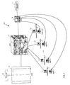
- Fig. 1 Shown in Fig. 1 is a communications system 100 shown in a context of use.
- the communications system 100 functions to selectively and automatically interconnect a caller 20 calling through the public switched telephone network (PSTN) 10 to one of a number of agent telephones 1-N (3, 6, or 11) where N may be a preselected number greater than one.
- PSTN public switched telephone network
- N may be a preselected number greater than one.
- ACD automatic call distributor
- PBX or centrex system may also be used in place of the ACD.
- implementing a call center with any of these switching systems is considered to be equivalent and variations will not be discussed further.
- automatic call distributors reference may be made to U.S. Pat. No. 5,268,903 to Jones et al.
- a packet-switched voice network or other equivalent network where voice calls are relayed to a call center may be used.
- voice calls are transmitted over a global network, such as the Internet using Internet Protocol (IP)
- IP Internet Protocol
- a packet-switched communications network may be used to implement the system of transmitting the call.
- the agent has a computer workstation consisting of a terminal and an input device, such as a keyboard or mouse.
- the agent telephone (3, 6, or 11), terminal and input device are collectively termed a "console.”
- a console is one type of physical entity in a call center.
- entity is used to refer to physical objects in a call center. For example, it may refer to an agent, console, supervisor, printer, or facsimile. In the illustrated embodiment, the term entity refers to a call center agent or a call center console; however, other physical objects may be monitored and displayed as described by the present invention.
- the ACD 9 also interfaces with a server computer 8.
- the server 8 functions to provide agent workstations (2, 5, 12) and supervisor workstation 14 with information from the ACD 9 and a database 7.
- agent workstations (2, 5, 12) and supervisor workstation 14
- call associated information e.g., ANI, DNIS, etc.
- the database 7 maintains performance statistics, customer information, and dial lists of the ACD 9 system.
- Server computer 8 may relay statistics and performance information maintained in database 7 to the supervisor workstation 14.
- a method for changing entity configuration information in a call center comprising the steps of:
- entity configuration information includes data such as staff ID, class of service, agent group, directory number, supervisor staff ID, schedule adherence threshold group, secondary agent group, agent information group, message queue, major class, and name.
- agent Bob having a staff ID of 1111 sitting at console 1234 would have the following related configuration information.
- Widget Sales Telephone Lines 1-200 directory number Staff member's phone extension 5455 supervisor staff ID Supervisor for Staff Carol Smith schedule adherence threshold group Associates Staff with certain thresholds 1 secondary agent group Sales, Service, Management, etc.
- Gizmo Sales Telephone Lines 1-220 agent information group Collection of organized agents, LINRs, or VRUs message queue ACD mail message queue to which agent is assigned 0 major class Type of staff, e.g. AGENT, SUPV, MASTER, and MAINT AGENT name Name of staff Bob Jones console Number of physical console unit 1234
- the step of automatically monitoring entities functions to provide an updated electronic floor plan of the call center to the supervisor of the call center.
- the step further comprises the steps of: (a) monitoring physical location information of entities to provide an electronic floor plan (see block 22 of FIG. 2), and (b) updating the electronic floor plan to provide and reflect a change in physical location information of the entities (see block 24).
- Physical location information includes x, y, and z Cartesian coordinates, latitude and longitude meridians, or radius vector and angle.
- console 60 may be referred to by its x, y, and z Cartesian coordinates as console (2, 2, 4). Further, the Cartesian coordinates are used to graphically describe the location of console 60 on a two-dimensional user interface.
- the step of monitoring physical location information of entities functions to provide an automatic trigger for changes in the physical location information.
- Monitoring means detecting physical location information for each entity in the system and noting changes when an entity moves.
- the step of updating an electronic floor plan means providing a call center supervisor with current entity configuration information regarding the entity within call center. Updating an electronic floor plan requires retrieving the recorded physical location information, translating the recorded physical location information into graphical form, and drawing the graphical form on an electronic floor plan.
- the physical location information is stored in the database 7 without meaning.
- the application that uses the physical location information dictates the meaning of the coordinates.
- the physical location information is represented in Cartesian x, y, z coordinates.
- a call center console projected onto a 2-dimensional device in the direction of the positive z axis has a positive x axis to the right and a positive y axis up.
- an application session begins on the supervisor workstation 14
- the supervisor workstation 14 connects to the server computer 8 (see block 1).
- an application session may begin by connecting directly to the ACD 9.
- entity objects are allocated and initialized to produce defined versions on the supervisor workstation 14 (see block 34). This step makes memory available on the supervisor workstation 14 for the physical location information of the entities in the call center.
- an event handler routine is initiated to execute whenever agent physical location information is changed (see block 36).
- the event handler runs in the background on the supervisor workstation 14 and is triggered by a change in x, y, z physical location information. If a change does occur, then the event handler executes software to update the electronic floor plan (see blocks 38-42).
- the new x, y, z physical location information is updated in the server computer 8 (see block 46). For example, when an agent moves from console 51 to console 52, the agent logs off console 51 and logs on to console 52. Thus, the agent's physical location has changed from (0, 3, 4) to (1, 3, 4).
- the new physical location information (1, 3, 4) is stored in the server computer 8.
- the new x, y, z physical location information is copied to the database 7 (see block 48).
- the new physical location information for the agent sitting at console 52 is (1, 3, 4) and is stored in the database 7.
- an application running on the supervisor workstation 14 may have a look-up table that keeps track of relationships between agents and consoles.
- the application running on the supervisor workstation would copy the physical location information from the server computer 8 or from the database 7 and maintain a look-up table of agents and consoles.
- Entity RTEvent Handler is triggered (see block 50) to perform an update of the electronic floor plan (blocks 38-42). Triggering or raising RTEvent for the new physical location information (see block 50) requires sending a signal to inform RTEvent that a change has occurred. When RTEvent receives the signal, it takes specified actions, namely updating the electronic floor plan (see blocks 38-42).
- the new physical location information is compared with the physical location information in the database 7 before RTEvent Handler was triggered. If the two are the same, then RTEvent Handler is not triggered. For example, the supervisor may delete an agent from the system and then immediately add the same agent to the same console. In such a situation, there is no need to redraw the electronic floor plan to reflect the change.
- Updating of the electronic floor plan is performed by reading the recorded physical location information, translating the recorded physical location information to graphical form, and drawing the graphical form on the electronic floor plan.
- Reading the recorded physical location information occurs when RTEvent is triggered (see block 36).
- Translating the recorded physical location information occurs by first verifying that the information contains x, y, z Cartesian coordinates (see block 38). If it does not, then the entity is placed in a list of entities with no location and displayed on the electronic floor plan as not having a location (see block 40). If the information contains x, y, z information, then the electronic floor plan is drawn to reflect this change (see block 42).
- a symbol representing an agent is placed at the console position that the agent is sitting at. For example, in FIG. 4, a graphical symbol of a man in a circle is used to depict the agent's occupied position.
- the electronic floor plan may be of any form reflecting the physical location of entities in the call center.
- the electronic floor plan may be drawn in a two-dimensional projection of the call center.
- each console 51 - 78 is displayed on the floor plan.
- the background image of the call center is predefined and may be specified as a rectangular floor plan.
- the agent who is sitting at a specific console is displayed on the electronic floor plan.
- FIG. 4 is a bitmap image of the floor plan.
- alternative embodiments may include vector or object oriented graphical images of the floor plan.
- the electronic floor plan may be drawn in a three-dimensional projection of the call center.
- a three-dimensional floor plan representing a specific call center may be created using virtual reality modeling language (VRML) and JavaScript code.
- VRML virtual reality modeling language
- the VRML electronic floor plan is updated with call center agent and console information.
- the VRML specification provides for taking Cartesian coordinates and performing a visual representation. Referring now to FIG. 5, a VRML image of a call center with six consoles is displayed. Further, the agent who is sitting at a specific console is displayed on the electronic floor plan.
- Alternative embodiments may include other three-dimensional modeling objects.
- the method may employ learning as a method of increasing the detection of changes in physical location.
- the method recognizes and learns agent location pattern regularities that appear over time. For example, agents assigned to consoles (55-60) regularly break for lunch during the noon hour. The method may recognize this pattern and learn that during such a time, the location of the agent is in the break room.
- the ability to predict physical location information may allow the call center supervisor to better predict agent absences and more efficiently manage the call center.
- the physical location information may be copied to the database 8 for use at a future date. Further, the physical location information may be archived so that the call center supervisor may perform historical analysis of the data to determine efficiencies of the call center and more particularly, call center agents.
Abstract
Description
- This invention relates to communications systems and, more particularly, to call centers.
- Communications systems with call centers are known. Such systems are typically used as a means of distributing telephone calls among a group of call center agents of an organization. As calls are directed to the organization from the public switch telephone network (PSTN), the communications system directs the calls to its call center agents based upon some algorithm. For example, a communications system such as an automatic call distributor (ACD), a public branch exchange (PBX), or a central office exchange service (centrex) may recognize a call target based upon an identity of an incoming trunk line and route the call accordingly.
- In call centers where many calls are received and handled by many call center agents, the call center may contain a large number of agents. Agents are responsible for servicing customers. Call center agents may provide product support, take sales orders, and handle inquires. In essence, the call center agents provide the wide array of services that the companies that use them require. Thus, the effectiveness and efficiency of a call center depends on the call center agents. Call center supervisors manage call center agents, including scheduling their tasks and duties, and are responsible for monitoring their whereabouts.
- To manage the call center efficiently, it is important for a call center supervisor to have ready access to the location of the call center agents. Currently, monitoring of the call center is performed manually by a paper or electronic floor plan image of the call center depicting the consoles that the agents sit at. To monitor the whereabouts of agents, tags representing agents are placed on the floor plan in the console position occupied by the agent.
- Such manual solutions may be inaccurate and may misrepresent an agent's physical location. For example, many call centers operate in hotdesking mode where agents sit at different seats according to availability and preference on a shift by shift basis. Thus, the floor plan may not represent the current agent and console locations. When an agent moves from one console to another, the call center supervisor must make note of the change by moving the tag representing the agent either on the paper or electronic floor plan. This requires the supervisor to constantly update the floor plan. If the supervisor looses track of agent positions, then some consoles identified as occupied may be mismarked. By not adequately tracking agents or consoles, the call center becomes underutilized and inefficient. Also, by being unaware of agents' whereabouts, the call center supervisor is unable to estimate the call center's capability.
- Further, even if the supervisor where to maintain an accurate floor plan, the supervisor is not able to reassign agents and make other configuration changes from the supervisor's desk. The supervisor must physically walk over to an agent's console and re-assign or re-configure the agent's console. Having the supervisor walk to each agent's console and perform the necessary changes is time consuming and inefficient.
- The existing method of monitoring physical locations of call center agents and consoles of communications systems requires the supervisor to manually track agents and consoles. As a consequence, many agents may be undetected or many unused consoles may be unused, and thereby, the quality of service provided by the call center may degrade. Further, the supervisor must physically walk to each and every console to perform the necessary changes to console configuration so that the call center is optimally performing. Accordingly, a need exists for a better way of changing agent and console information while automatically monitoring and displaying such information in a call center.
- The present invention, accordingly, provides a system and method of changing entity configuration information that overcomes or reduces the disadvantageous and limitations associated with prior agent monitoring methods and systems. Illustrated embodiments reduce the disadvantage of manually tracking agents and consoles in a call center by automatically monitoring entities in a call center, selecting an entity in the call center, and modifying configuration information of the selected entity. An electronic floor plan that depicts the locations of the entities, displays the entity configuration information and is automatically updated when changes occur is disclosed. In an exemplary embodiment, call center supervisors are able to view accurate physical location information for call center agents and consoles on a two-dimensional or three-dimensional electronic floor plan. Further, the call center supervisors are able to change entity configuration information by selecting an entity from the electronic floor plan.
- The foregoing advantageous features of the invention will be explained in greater detail and others will be made apparent from the detailed description of the preferred embodiment of the present invention which is given with reference to the several figures of the drawing, in which:
- FIG. 1 is a simplified functional block diagram of the automatic call distribution system in accordance with an illustrated embodiment of the invention;
- FIG. 2 is a simplified flow chart of the method used by the system of FIG. 1;
- FIG. 3 is a simplified flow chart of an embodiment of the method disclosed in FIG. 2;
- FIG. 4 is a diagram depicting a two-dimensional electronic floor plan used by the system of FIG. 1; and
- FIG. 5 is a diagram depicting a three-dimensional electronic floor plan used by the system of FIG. 1.
-
- Shown in Fig. 1 is a
communications system 100 shown in a context of use. Thecommunications system 100 functions to selectively and automatically interconnect acaller 20 calling through the public switched telephone network (PSTN) 10 to one of a number of agent telephones 1-N (3, 6, or 11) where N may be a preselected number greater than one. Although thecommunications system 100 is described with reference to an automatic call distributor (ACD), a PBX or centrex system may also be used in place of the ACD. Further, implementing a call center with any of these switching systems is considered to be equivalent and variations will not be discussed further. For a more detailed discussion of automatic call distributors, reference may be made to U.S. Pat. No. 5,268,903 to Jones et al. entitled "Multichannel Telephonic Switching Network With Different Signaling Formats and Connect/PBX Treatment Selectable For Each Channel", issued December 7, 1993; U.S. Pat. No. 5,140,611 to Jones et al. entitled "Pulse Modulated Self-Clocking and Self-Synchronizing Data Transmission and Method for a Telephonic Communication Switching System", issued Aug. 8, 1992 and U.S. Pat. No. 5,127,004 to Lenihan et al. entitled "Tone and Announcement Message Code Generator for a Telephonic Switching System and Method", issued Jun. 30, 1992. - Further, although the present invention is described in reference to the
PSTN 10, a packet-switched voice network or other equivalent network where voice calls are relayed to a call center may be used. For example, where voice calls are transmitted over a global network, such as the Internet using Internet Protocol (IP) a packet-switched communications network may be used to implement the system of transmitting the call. - In addition to the agent telephone (3, 6, or 11), the agent has a computer workstation consisting of a terminal and an input device, such as a keyboard or mouse. The agent telephone (3, 6, or 11), terminal and input device are collectively termed a "console." A console is one type of physical entity in a call center. The term entity is used to refer to physical objects in a call center. For example, it may refer to an agent, console, supervisor, printer, or facsimile. In the illustrated embodiment, the term entity refers to a call center agent or a call center console; however, other physical objects may be monitored and displayed as described by the present invention.
- In addition to the agent telephones (3, 6, 11), the ACD 9 also interfaces with a server computer 8. The server 8 functions to provide agent workstations (2, 5, 12) and
supervisor workstation 14 with information from the ACD 9 and adatabase 7. For example, as calls are received from thePSTN 10, call associated information (e.g., ANI, DNIS, etc.) may be delivered to the agent along with the call. Thedatabase 7 maintains performance statistics, customer information, and dial lists of the ACD 9 system. Server computer 8 may relay statistics and performance information maintained indatabase 7 to thesupervisor workstation 14. - In accordance with an embodiment of the present invention, a method for changing entity configuration information in a call center comprising the steps of:
- (a) automatically monitoring entities in a call center,
- (b) selecting an entity in the call center, and (c) modifying configuration information of the selected entity. The step of automatically monitoring entities is further described below. The step of selecting an entity functions to provide the supervisor with a way to focus on an entity in the call center without having to physically walk over to the entity. In an exemplary embodiment, selecting an entity is accomplished by placing a selection device, such as a mouse, over a pictorial image of the entity and double clicking on the image. Selection may also be performed by the use of a pen-based or voice recognition device that performs the same function. The step of modifying entity configuration information functions to allow the supervisor to change parameters or data associated with a specific entity without having to walk over to the entity and make those changes. This may be accomplished by typing in configuration information via a keyboard or via selection of configuration parameters by the mouse.
-
- In an exemplary embodiment, entity configuration information includes data such as staff ID, class of service, agent group, directory number, supervisor staff ID, schedule adherence threshold group, secondary agent group, agent information group, message queue, major class, and name. For example, agent Bob having a staff ID of 1111 sitting at console 1234 would have the following related configuration information.
Configuration Name Description Value staff ID Sign-in Number associated with a Person 1111 class of service AGENT, SUPV, MASTER, MAINT, VRU, VMAIL, FAX, PHONE, or TRUNK AGENT agent group Sales, Service, Management, etc. Widget Sales Telephone Lines, 1-200 directory number Staff member's phone extension 5455 supervisor staff ID Supervisor for Staff Carol Smith schedule adherence threshold group Associates Staff with certain thresholds 1 secondary agent group Sales, Service, Management, etc. Gizmo Sales Telephone Lines, 1-220 agent information group Collection of organized agents, LINRs, or VRUs message queue ACD mail message queue to which agent is assigned 0 major class Type of staff, e.g. AGENT, SUPV, MASTER, and MAINT AGENT name Name of staff Bob Jones console Number of physical console unit 1234 - The step of automatically monitoring entities functions to provide an updated electronic floor plan of the call center to the supervisor of the call center. The step further comprises the steps of: (a) monitoring physical location information of entities to provide an electronic floor plan (see
block 22 of FIG. 2), and (b) updating the electronic floor plan to provide and reflect a change in physical location information of the entities (see block 24). Physical location information includes x, y, and z Cartesian coordinates, latitude and longitude meridians, or radius vector and angle. As an example, referring now to FIG. 4, console 60 may be referred to by its x, y, and z Cartesian coordinates as console (2, 2, 4). Further, the Cartesian coordinates are used to graphically describe the location of console 60 on a two-dimensional user interface. - The step of monitoring physical location information of entities functions to provide an automatic trigger for changes in the physical location information. Monitoring means detecting physical location information for each entity in the system and noting changes when an entity moves. The step of updating an electronic floor plan means providing a call center supervisor with current entity configuration information regarding the entity within call center. Updating an electronic floor plan requires retrieving the recorded physical location information, translating the recorded physical location information into graphical form, and drawing the graphical form on an electronic floor plan.
- In one embodiment the physical location information is stored in the
database 7 without meaning. The application that uses the physical location information dictates the meaning of the coordinates. For example, in a VRML representation of the call center, the physical location information is represented in Cartesian x, y, z coordinates. A call center console projected onto a 2-dimensional device in the direction of the positive z axis has a positive x axis to the right and a positive y axis up. - Referring now to FIG. 3, as an application session (see block 30) begins on the
supervisor workstation 14, thesupervisor workstation 14 connects to the server computer 8 (see block 1). In an alternative embodiment, an application session may begin by connecting directly to theACD 9. Next, entity objects are allocated and initialized to produce defined versions on the supervisor workstation 14 (see block 34). This step makes memory available on thesupervisor workstation 14 for the physical location information of the entities in the call center. - Further, an event handler routine is initiated to execute whenever agent physical location information is changed (see block 36). The event handler runs in the background on the
supervisor workstation 14 and is triggered by a change in x, y, z physical location information. If a change does occur, then the event handler executes software to update the electronic floor plan (see blocks 38-42). - When a new entity or an existing entity is modified (see block 44), the new x, y, z physical location information is updated in the server computer 8 (see block 46). For example, when an agent moves from console 51 to console 52, the agent logs off console 51 and logs on to console 52. Thus, the agent's physical location has changed from (0, 3, 4) to (1, 3, 4). In one embodiment, the new physical location information (1, 3, 4) is stored in the server computer 8. Then, the new x, y, z physical location information is copied to the database 7 (see block 48). In the above example, the new physical location information for the agent sitting at console 52 is (1, 3, 4) and is stored in the
database 7. - In one embodiment, an application running on the
supervisor workstation 14 may have a look-up table that keeps track of relationships between agents and consoles. In such an embodiment, the application running on the supervisor workstation would copy the physical location information from the server computer 8 or from thedatabase 7 and maintain a look-up table of agents and consoles. - After the change is made in the database, Entity RTEvent Handler is triggered (see block 50) to perform an update of the electronic floor plan (blocks 38-42). Triggering or raising RTEvent for the new physical location information (see block 50) requires sending a signal to inform RTEvent that a change has occurred. When RTEvent receives the signal, it takes specified actions, namely updating the electronic floor plan (see blocks 38-42).
- In an alternative embodiment, the new physical location information is compared with the physical location information in the
database 7 before RTEvent Handler was triggered. If the two are the same, then RTEvent Handler is not triggered. For example, the supervisor may delete an agent from the system and then immediately add the same agent to the same console. In such a situation, there is no need to redraw the electronic floor plan to reflect the change. - Updating of the electronic floor plan is performed by reading the recorded physical location information, translating the recorded physical location information to graphical form, and drawing the graphical form on the electronic floor plan. Reading the recorded physical location information occurs when RTEvent is triggered (see block 36). Translating the recorded physical location information occurs by first verifying that the information contains x, y, z Cartesian coordinates (see block 38). If it does not, then the entity is placed in a list of entities with no location and displayed on the electronic floor plan as not having a location (see block 40). If the information contains x, y, z information, then the electronic floor plan is drawn to reflect this change (see block 42). In an exemplary embodiment, a symbol representing an agent is placed at the console position that the agent is sitting at. For example, in FIG. 4, a graphical symbol of a man in a circle is used to depict the agent's occupied position. However, the electronic floor plan may be of any form reflecting the physical location of entities in the call center.
- Under an illustrated embodiment, the electronic floor plan may be drawn in a two-dimensional projection of the call center. Referring now to FIG. 4, each console (51 - 78) is displayed on the floor plan. The background image of the call center is predefined and may be specified as a rectangular floor plan. Further, the agent who is sitting at a specific console is displayed on the electronic floor plan. FIG. 4 is a bitmap image of the floor plan. However, alternative embodiments may include vector or object oriented graphical images of the floor plan.
- Under another illustrated embodiment, the electronic floor plan may be drawn in a three-dimensional projection of the call center. A three-dimensional floor plan representing a specific call center may be created using virtual reality modeling language (VRML) and JavaScript code. By accessing the physical location information in either the server computer 8 or the
database 7, the VRML electronic floor plan is updated with call center agent and console information. The VRML specification provides for taking Cartesian coordinates and performing a visual representation. Referring now to FIG. 5, a VRML image of a call center with six consoles is displayed. Further, the agent who is sitting at a specific console is displayed on the electronic floor plan. Alternative embodiments may include other three-dimensional modeling objects. - In an alternative embodiment, the method may employ learning as a method of increasing the detection of changes in physical location. The method recognizes and learns agent location pattern regularities that appear over time. For example, agents assigned to consoles (55-60) regularly break for lunch during the noon hour. The method may recognize this pattern and learn that during such a time, the location of the agent is in the break room. The ability to predict physical location information may allow the call center supervisor to better predict agent absences and more efficiently manage the call center.
- At the end of an application session, the physical location information may be copied to the database 8 for use at a future date. Further, the physical location information may be archived so that the call center supervisor may perform historical analysis of the data to determine efficiencies of the call center and more particularly, call center agents.
- A specific embodiment of a system and method of monitoring entities according to the present invention has been described for the purpose of illustrating the manner in which the invention is made and used. It should be understood that the implementation of other variations and modifications of the invention and its various aspects will be apparent to one skilled in the art, and that the invention is not limited by the specific embodiments described. Therefore, it is contemplated to cover the present invention, any and all modifications, variations, or equivalents that fall within the true spirit and scope of the basic underlying principles disclosed and claimed herein.
Claims (52)
- A method of changing entity configuration information in a call center comprising the steps of:automatically monitoring entities in a call center;selecting an entity in the call center; andmodifying configuration information of the selected entity.
- The method of changing entity configuration information as in claim 1 wherein the step of automatically monitoring entities further comprises the steps of:monitoring physical location information of entities to provide an electronic floor plan; andupdating the electronic floor plan to provide and reflect a change in physical location information of the entities.
- The method of changing entity configuration information as in claim 2 wherein physical location information includes Cartesian coordinates, latitude and longitude meridians, and radius vector and angle.
- The method of changing entity configuration information as in claim 2 wherein entities includes call center agents, consoles, printers, and facsimile machines.
- The method of changing entity configuration information as in claim 2 wherein the electronic floor plan includes a bit map image, vector graphics, object oriented graphics, and VRML representation of the call center.
- The method of changing entity configuration information as in claim 2 wherein the step of monitoring changes further comprises comparing physical location at a second time with physical location at a first time.
- The method of changing entity configuration information as in claim 2 wherein updating further comprises notifying a supervisor if the physical location information has been changed.
- The method of changing entity configuration information as in claim 2 wherein the step of monitoring physical location information further comprises:recording physical location information; andretrieving the recorded physical location information.
- The method of changing entity configuration information as in claim 8 wherein the physical location information is entered by a call center user.
- The method of changing entity configuration information as in claim 8 wherein the physical location information is entered by a server computer.
- The method of changing entity configuration information as in claim 8 wherein updating further comprises:retrieving the recorded physical location information;translating the recorded physical location information to graphical form; anddrawing the graphical form on the electronic floor plan.
- The method of changing entity configuration information as in claim 11 wherein the recorded physical location information is determined by getting physical location information from a database of call center information.
- The method of changing entity configuration information as in claim 11 wherein the step of translating includes using a look-up table to create a relationship between physical location information and graphical form.
- The method of changing entity configuration information as in claim 11 wherein the step of translating further comprises determining whether the recorded physical location information contains proper Cartesian coordinates.
- The method of changing entity configuration information as in claim 13 wherein proper is information that can be graphically represented on the electronic floor plan.
- The method of changing entity configuration information as in claim 13 wherein recorded physical location information that is improper is maintained in a list of entities without physical location information.
- The method of changing entity configuration information as in claim 11 wherein the step of drawing further comprises the step of placing a graphical image on the electronic floor plan.
- The method of changing entity configuration information as in claim 17 wherein the step of drawing is performed by using bit map drawing tools to produce a two-dimensional image of the electronic floor plan.
- The method of changing entity configuration information as in claim 17 wherein the step of drawing is performed by using VRML code to produce a three-dimensional image of the electronic floor plan.
- The method of changing entity configuration information as in claim 2 wherein the step of monitoring further comprises identifying an entity which has physically moved.
- The method of changing entity configuration information as in claim 2 wherein the electronic floor plan is updated with a prediction of physical location information based upon a history of physical location information.
- The method of changing entity configuration information as in claim 2 wherein the physical location information is archived and retrieved for later analysis.
- A system of changing entity configuration in a call center, such system comprising:means for monitoring physical location information of entities to provide an electronic floor plan; andmeans for updating the electronic floor plan to provide and reflect the changes in physical location information of the entities.
- The system of changing entity configuration as in claim 23 wherein entities includes call center agents, consoles, printers, and facsimile machines.
- The system of changing entity configuration as in claim 23 wherein the electronic floor plan includes a bit map image, vector graphics, object oriented graphics, and VRML representation of the call center.
- The system of changing entity configuration as in claim 23 further comprising means for comparing physical location at a second time with physical location at a first time.
- The system of changing entity configuration as in claim 23 wherein the means for updating further comprises means for notifying a supervisor if the physical location information has been changed.
- The system of changing entity configuration as in claim 23 wherein the means for monitoring physical location information further comprises:means for recording physical location information; andmeans for retrieving the physical location information.
- The system of changing entity configuration as in claim 28 wherein the physical location information is entered by a call center user.
- The system of changing entity configuration as in claim 28 wherein the physical location information is entered by a server computer.
- The system of changing entity configuration as in claim 28 wherein the means for updating further comprises:means for reading the recorded physical location information;means for translating the recorded physical location information to graphical form; andmeans for drawing the graphical form on the electronic floor plan.
- The system of changing entity configuration as in claim 31 wherein the physical location information is stored in a database of call center information.
- The system of changing entity configuration as in claim 31 wherein the means for reading further comprises means for retrieving physical location information from a database of call center information.
- The system of changing entity configuration as in claim 31 wherein the means for translating includes a look-up table of relationships between physical location information and graphical form.
- The system of changing entity configuration as in claim 31 wherein the means for translating further comprises means for determining whether the recorded physical location information contains proper Cartesian coordinates.
- The system of changing entity configuration as in claim 34 wherein proper is information that can be graphically represented on the electronic floor plan.
- The system of changing entity configuration as in claim 34 wherein recorded physical location information that is improper is maintained in a list of entities without physical location information.
- The system of changing entity configuration as in claim 34 wherein the means for drawing further comprises means of placing a graphical image on the electronic floor plan.
- The system of changing entity configuration as in claim 34 wherein the means for drawing includes bit map and VRML drawings tools.
- The system of changing entity configuration as in claim 23 wherein the means for monitoring further comprises means for identifying an entity which has physically moved.
- The system of changing entity configuration as in claim 23 further comprising means for predicting physical location information based upon a history of physical location information.
- The system of changing entity configuration as in claim 23 further comprising means for storing archived physical location information.
- The system of changing entity configuration as in claim 42 further comprising means for retrieving the archived physical location information.
- A system of changing entity configuration in a communications system, such system comprising:an entity monitor which monitors entities for physical location information to provide an electronic floor plan; andan informer that updates the electronic floor plan to provide and reflect changes in physical location information of the entities.
- The system of changing entity configuration as in claim 44 wherein the call monitor comprises a programmable computer.
- The system of changing entity configuration as in claim 44 wherein entities includes call center agents, consoles, printers, and facsimile machines.
- The system of changing entity configuration as in claim 44 wherein the electronic floor plan includes a bit map image, vector graphics, object oriented graphics, and VRML representation of the call center.
- The system of changing entity configuration as in claim 44 wherein the entity monitor further comprises an evaluator which compares physical location at a second time with physical location at a first time.
- The system of changing entity configuration as in claim 44 wherein the informer further comprises a notifier which alerts a supervisor if the physical location information has changed.
- The system of changing entity configuration as in claim 44 wherein the entity monitor further comprises:a recorder for storing physical location information; anda retriever for getting the stored physical location information.
- The system of changing entity configuration as in claim 50 wherein the informer further comprises:a reader which retrieves the recorded physical location information;a translator for relating the recorded physical location information to graphical form; anda drawer which places the graphical form on the electronic floor plan.
- The system of changing entity configuration as in claim 51 wherein the translator includes a look-up table of relationships between physical location information and graphical form.
Applications Claiming Priority (2)
| Application Number | Priority Date | Filing Date | Title |
|---|---|---|---|
| US584306 | 2000-05-31 | ||
| US09/584,306 US6987846B1 (en) | 2000-05-31 | 2000-05-31 | System and method of changing entity configuration information while automatically monitoring and displaying such information in a call center |
Publications (2)
| Publication Number | Publication Date |
|---|---|
| EP1161069A2 true EP1161069A2 (en) | 2001-12-05 |
| EP1161069A3 EP1161069A3 (en) | 2003-10-29 |
Family
ID=24336767
Family Applications (1)
| Application Number | Title | Priority Date | Filing Date |
|---|---|---|---|
| EP01250152A Withdrawn EP1161069A3 (en) | 2000-05-31 | 2001-04-30 | System and method of changing entity configuration information while automatically monitoring and displaying such information in a call center |
Country Status (4)
| Country | Link |
|---|---|
| US (1) | US6987846B1 (en) |
| EP (1) | EP1161069A3 (en) |
| AU (1) | AU776586B2 (en) |
| CA (1) | CA2344756A1 (en) |
Families Citing this family (12)
| Publication number | Priority date | Publication date | Assignee | Title |
|---|---|---|---|---|
| US7421072B2 (en) * | 2002-10-04 | 2008-09-02 | Avaya Inc | Location-based bridging in call centers |
| US7599861B2 (en) | 2006-03-02 | 2009-10-06 | Convergys Customer Management Group, Inc. | System and method for closed loop decisionmaking in an automated care system |
| US7809663B1 (en) | 2006-05-22 | 2010-10-05 | Convergys Cmg Utah, Inc. | System and method for supporting the utilization of machine language |
| US8379830B1 (en) | 2006-05-22 | 2013-02-19 | Convergys Customer Management Delaware Llc | System and method for automated customer service with contingent live interaction |
| US8619968B2 (en) * | 2010-04-14 | 2013-12-31 | Avaya Inc. | View and metrics for a queueless contact center |
| US9571654B2 (en) | 2010-04-14 | 2017-02-14 | Avaya Inc. | Bitmaps for next generation contact center |
| US8670550B2 (en) | 2010-04-14 | 2014-03-11 | Avaya Inc. | Automated mechanism for populating and maintaining data structures in a queueless contact center |
| US9251504B2 (en) | 2011-08-29 | 2016-02-02 | Avaya Inc. | Configuring a virtual reality environment in a contact center |
| JP5728692B2 (en) * | 2011-09-09 | 2015-06-03 | ピーアンドダブリューソリューションズ株式会社 | Arrangement design apparatus, method and program |
| JP5776084B2 (en) * | 2011-09-27 | 2015-09-09 | ピーアンドダブリューソリューションズ株式会社 | SEATING DEVICE, SEATING METHOD, AND SEATING PROGRAM |
| US8688684B2 (en) | 2012-04-06 | 2014-04-01 | Avaya Inc. | Qualifier set creation for work assignment engine |
| US10178473B2 (en) | 2014-09-05 | 2019-01-08 | Plantronics, Inc. | Collection and analysis of muted audio |
Family Cites Families (9)
| Publication number | Priority date | Publication date | Assignee | Title |
|---|---|---|---|---|
| US5375161A (en) * | 1984-09-14 | 1994-12-20 | Accessline Technologies, Inc. | Telephone control system with branch routing |
| US5493692A (en) * | 1993-12-03 | 1996-02-20 | Xerox Corporation | Selective delivery of electronic messages in a multiple computer system based on context and environment of a user |
| US5515426A (en) * | 1994-02-28 | 1996-05-07 | Executone Information Systems, Inc. | Telephone communication system having a locator |
| US5465286A (en) * | 1994-05-24 | 1995-11-07 | Executone Information Systems, Inc. | Apparatus for supervising an automatic call distribution telephone system |
| US5742675A (en) * | 1995-09-26 | 1998-04-21 | Telefonaktiebolaget Lm Ericsson | Method and apparatus for automatically distributing calls to available logged-in call handling agents |
| US6064730A (en) * | 1996-06-18 | 2000-05-16 | Lucent Technologies Inc. | Customer-self routing call center |
| JP3932461B2 (en) * | 1997-05-21 | 2007-06-20 | ソニー株式会社 | Client device, image display control method, shared virtual space providing device and method, and recording medium |
| US6466663B1 (en) * | 1997-09-30 | 2002-10-15 | Don Ravenscroft | Monitoring system client for a call center |
| US6577726B1 (en) * | 2000-03-31 | 2003-06-10 | Siebel Systems, Inc. | Computer telephony integration hotelling method and system |
-
2000
- 2000-05-31 US US09/584,306 patent/US6987846B1/en not_active Expired - Lifetime
-
2001
- 2001-04-18 CA CA002344756A patent/CA2344756A1/en not_active Abandoned
- 2001-04-30 EP EP01250152A patent/EP1161069A3/en not_active Withdrawn
- 2001-05-04 AU AU43721/01A patent/AU776586B2/en not_active Ceased
Non-Patent Citations (1)
| Title |
|---|
| None * |
Also Published As
| Publication number | Publication date |
|---|---|
| AU4372101A (en) | 2001-12-06 |
| CA2344756A1 (en) | 2001-11-30 |
| EP1161069A3 (en) | 2003-10-29 |
| AU776586B2 (en) | 2004-09-16 |
| US6987846B1 (en) | 2006-01-17 |
Similar Documents
| Publication | Publication Date | Title |
|---|---|---|
| US10447855B1 (en) | Agent training sensitive call routing system | |
| US6704410B1 (en) | System for automatically assigning skill levels to multiple skilled agents in call center agent assignment applications | |
| EP1349357B1 (en) | Call center system | |
| US5903877A (en) | Transaction center for processing customer transaction requests from alternative media sources | |
| US5715307A (en) | Integrated voice and business transaction reporting for telephone call centers | |
| US6681010B1 (en) | Methods, systems and computer program products for automatic task distribution | |
| EP0982915B1 (en) | Automatic call distribution and training system | |
| US7085366B2 (en) | System and method for telemarketing through a hypertext network | |
| US5832059A (en) | Call path system and method for modeling and modifying a call path of a telephone call routed by a telephone switch | |
| US7817796B1 (en) | Coordinating work assignments for contact center agents | |
| US6987846B1 (en) | System and method of changing entity configuration information while automatically monitoring and displaying such information in a call center | |
| US20040044585A1 (en) | Customer service management system | |
| EP0802665A2 (en) | Work at home acd agent network with cooperative control | |
| JP2001517028A (en) | Method and apparatus for determining agent availability | |
| JPH10504425A (en) | Equipment for monitoring automatic call distribution telephone systems | |
| US9544435B1 (en) | System and method for real-time geographical call display of automatic call distributor calls | |
| US6654798B1 (en) | Automatic contact distribution system definable agent log-off reasons | |
| US20030191632A1 (en) | Utilization of agent idle time in a communication system | |
| GB2387738A (en) | Contact centre data integration with enterprise applications | |
| US8582751B2 (en) | Systems and methods for discovering customer center information | |
| US8588396B2 (en) | Method for reporting activity of multi-appearance call-center agent | |
| US8229098B2 (en) | Network router for heterogeneous ACD system | |
| JP4308081B2 (en) | Incoming call distribution system, incoming call distribution method, and incoming call distribution control device | |
| US8503661B2 (en) | Single workflow for colloborative network routing over heteogeneous system | |
| JP2006185319A (en) | Customer handling support method and customer handling support system |
Legal Events
| Date | Code | Title | Description |
|---|---|---|---|
| PUAI | Public reference made under article 153(3) epc to a published international application that has entered the european phase |
Free format text: ORIGINAL CODE: 0009012 |
|
| AK | Designated contracting states |
Kind code of ref document: A2 Designated state(s): AT BE CH CY DE DK ES FI FR GB GR IE IT LI LU MC NL PT SE TR |
|
| AX | Request for extension of the european patent |
Free format text: AL;LT;LV;MK;RO;SI |
|
| 17P | Request for examination filed |
Effective date: 20011113 |
|
| PUAL | Search report despatched |
Free format text: ORIGINAL CODE: 0009013 |
|
| AK | Designated contracting states |
Kind code of ref document: A3 Designated state(s): AT BE CH CY DE DK ES FI FR GB GR IE IT LI LU MC NL PT SE TR |
|
| AX | Request for extension of the european patent |
Extension state: AL LT LV MK RO SI |
|
| RIC1 | Information provided on ipc code assigned before grant |
Ipc: 7H 04M 3/51 B Ipc: 7H 04M 3/523 A |
|
| AKX | Designation fees paid |
Designated state(s): AT BE CH CY DE DK ES FI FR GB GR IE IT LI LU MC NL PT SE TR |
|
| 17Q | First examination report despatched |
Effective date: 20070131 |
|
| STAA | Information on the status of an ep patent application or granted ep patent |
Free format text: STATUS: THE APPLICATION IS DEEMED TO BE WITHDRAWN |
|
| 18D | Application deemed to be withdrawn |
Effective date: 20101112 |