EP1162632A2 - Communications cables with isolators - Google Patents
Communications cables with isolators Download PDFInfo
- Publication number
- EP1162632A2 EP1162632A2 EP01304730A EP01304730A EP1162632A2 EP 1162632 A2 EP1162632 A2 EP 1162632A2 EP 01304730 A EP01304730 A EP 01304730A EP 01304730 A EP01304730 A EP 01304730A EP 1162632 A2 EP1162632 A2 EP 1162632A2
- Authority
- EP
- European Patent Office
- Prior art keywords
- spacer
- cable
- longitudinally extending
- cable jacket
- wall portions
- Prior art date
- Legal status (The legal status is an assumption and is not a legal conclusion. Google has not performed a legal analysis and makes no representation as to the accuracy of the status listed.)
- Granted
Links
- 125000006850 spacer group Chemical group 0.000 claims abstract description 94
- 239000004020 conductor Substances 0.000 claims abstract description 65
- 230000007423 decrease Effects 0.000 claims description 24
- 230000003247 decreasing effect Effects 0.000 claims description 2
- 239000000463 material Substances 0.000 description 18
- 238000004519 manufacturing process Methods 0.000 description 17
- 238000000034 method Methods 0.000 description 17
- 239000011810 insulating material Substances 0.000 description 9
- -1 polyethylene Polymers 0.000 description 5
- 239000004800 polyvinyl chloride Substances 0.000 description 5
- 229920000915 polyvinyl chloride Polymers 0.000 description 5
- 238000000926 separation method Methods 0.000 description 5
- 230000002411 adverse Effects 0.000 description 4
- RNFJDJUURJAICM-UHFFFAOYSA-N 2,2,4,4,6,6-hexaphenoxy-1,3,5-triaza-2$l^{5},4$l^{5},6$l^{5}-triphosphacyclohexa-1,3,5-triene Chemical compound N=1P(OC=2C=CC=CC=2)(OC=2C=CC=CC=2)=NP(OC=2C=CC=CC=2)(OC=2C=CC=CC=2)=NP=1(OC=1C=CC=CC=1)OC1=CC=CC=C1 RNFJDJUURJAICM-UHFFFAOYSA-N 0.000 description 3
- 239000004812 Fluorinated ethylene propylene Substances 0.000 description 3
- 229920001577 copolymer Polymers 0.000 description 3
- 239000003063 flame retardant Substances 0.000 description 3
- 229920002313 fluoropolymer Polymers 0.000 description 3
- 238000012986 modification Methods 0.000 description 3
- 230000004048 modification Effects 0.000 description 3
- 229920009441 perflouroethylene propylene Polymers 0.000 description 3
- 239000002861 polymer material Substances 0.000 description 3
- 239000004698 Polyethylene Substances 0.000 description 2
- 239000004743 Polypropylene Substances 0.000 description 2
- 239000000956 alloy Substances 0.000 description 2
- 229910045601 alloy Inorganic materials 0.000 description 2
- 229910052782 aluminium Inorganic materials 0.000 description 2
- XAGFODPZIPBFFR-UHFFFAOYSA-N aluminium Chemical compound [Al] XAGFODPZIPBFFR-UHFFFAOYSA-N 0.000 description 2
- 238000001125 extrusion Methods 0.000 description 2
- 239000000203 mixture Substances 0.000 description 2
- 229920000573 polyethylene Polymers 0.000 description 2
- 229920001155 polypropylene Polymers 0.000 description 2
- BFKJFAAPBSQJPD-UHFFFAOYSA-N tetrafluoroethene Chemical group FC(F)=C(F)F BFKJFAAPBSQJPD-UHFFFAOYSA-N 0.000 description 2
- BLTXWCKMNMYXEA-UHFFFAOYSA-N 1,1,2-trifluoro-2-(trifluoromethoxy)ethene Chemical compound FC(F)=C(F)OC(F)(F)F BLTXWCKMNMYXEA-UHFFFAOYSA-N 0.000 description 1
- BZPCMSSQHRAJCC-UHFFFAOYSA-N 1,2,3,3,4,4,5,5,5-nonafluoro-1-(1,2,3,3,4,4,5,5,5-nonafluoropent-1-enoxy)pent-1-ene Chemical compound FC(F)(F)C(F)(F)C(F)(F)C(F)=C(F)OC(F)=C(F)C(F)(F)C(F)(F)C(F)(F)F BZPCMSSQHRAJCC-UHFFFAOYSA-N 0.000 description 1
- 239000004604 Blowing Agent Substances 0.000 description 1
- OKTJSMMVPCPJKN-UHFFFAOYSA-N Carbon Chemical compound [C] OKTJSMMVPCPJKN-UHFFFAOYSA-N 0.000 description 1
- RYGMFSIKBFXOCR-UHFFFAOYSA-N Copper Chemical compound [Cu] RYGMFSIKBFXOCR-UHFFFAOYSA-N 0.000 description 1
- 229920007925 Ethylene chlorotrifluoroethylene (ECTFE) Polymers 0.000 description 1
- 239000006057 Non-nutritive feed additive Substances 0.000 description 1
- 229910000831 Steel Inorganic materials 0.000 description 1
- 239000004809 Teflon Substances 0.000 description 1
- 229920006362 Teflon® Polymers 0.000 description 1
- 239000000370 acceptor Substances 0.000 description 1
- 239000002253 acid Substances 0.000 description 1
- 239000000654 additive Substances 0.000 description 1
- 229910000410 antimony oxide Inorganic materials 0.000 description 1
- 238000005452 bending Methods 0.000 description 1
- 230000005540 biological transmission Effects 0.000 description 1
- 238000007664 blowing Methods 0.000 description 1
- 229910052799 carbon Inorganic materials 0.000 description 1
- 238000010276 construction Methods 0.000 description 1
- 229910052802 copper Inorganic materials 0.000 description 1
- 239000010949 copper Substances 0.000 description 1
- KAATUXNTWXVJKI-UHFFFAOYSA-N cypermethrin Chemical compound CC1(C)C(C=C(Cl)Cl)C1C(=O)OC(C#N)C1=CC=CC(OC=2C=CC=CC=2)=C1 KAATUXNTWXVJKI-UHFFFAOYSA-N 0.000 description 1
- 229920005570 flexible polymer Polymers 0.000 description 1
- 239000004088 foaming agent Substances 0.000 description 1
- 239000011888 foil Substances 0.000 description 1
- 238000009434 installation Methods 0.000 description 1
- 229910052751 metal Inorganic materials 0.000 description 1
- 239000002184 metal Substances 0.000 description 1
- 239000012811 non-conductive material Substances 0.000 description 1
- 239000002667 nucleating agent Substances 0.000 description 1
- VTRUBDSFZJNXHI-UHFFFAOYSA-N oxoantimony Chemical compound [Sb]=O VTRUBDSFZJNXHI-UHFFFAOYSA-N 0.000 description 1
- 239000000049 pigment Substances 0.000 description 1
- 239000004065 semiconductor Substances 0.000 description 1
- 239000010959 steel Substances 0.000 description 1
- 239000003017 thermal stabilizer Substances 0.000 description 1
Images


Classifications
-
- H—ELECTRICITY
- H01—ELECTRIC ELEMENTS
- H01B—CABLES; CONDUCTORS; INSULATORS; SELECTION OF MATERIALS FOR THEIR CONDUCTIVE, INSULATING OR DIELECTRIC PROPERTIES
- H01B11/00—Communication cables or conductors
- H01B11/02—Cables with twisted pairs or quads
- H01B11/06—Cables with twisted pairs or quads with means for reducing effects of electromagnetic or electrostatic disturbances, e.g. screens
Definitions
- the longitudinally extending wall portions may have a first radial section and a second radial section having a knob shaped cross-section.
- the knob shaped cross-section may be any portion of a knob including a half knob and/or a whole knob.
- the shield 16 is located between the spacer 14 and the cable jacket 12 and is preferably longitudinally coextensive with the cable jacket 12.
- the shield 16 may be made from a wide variety of known conductive and/or nonconductive materials such as nonconductive polymeric tape; conductive tape; braid; a combination of nonconductive polymeric tape, conductive tape and/or braid; and/or other such materials as will be understood to one of skill in the art using conventional fabrication techniques.
- the shield 16 may include one or more layers of material 16a, 16b and may be applied longitudinally, helically, etc. and/or may be braided as will be understood to one of skill in the art. As will be understood by one of skill in the art, the shield 16 can be omitted from the communications cable 10.
- the communications cable 210 includes a cable jacket 212, a spacer 214, a plurality of twisted pairs of insulated conductors 220, 222, 224, 226, a shield 216 and a plurality of compartments 240, 242, 244, 246. It will, however, be understood that the shield 216 may be omitted.
- the spacer 214 is situated within and is longitudinally coextensive with the cable jacket 212.
- the spacer 214 may comprise the same materials and may be fabricated using the same fabrication techniques that were discussed in connection with the spacer 14.
- the spacer 214 includes a longitudinally extending center portion 230 and a plurality of longitudinally extending wall portions 232, 234, 236, 238 radiating from the center portion 230.
- Each individual wall portion 232, 234, 236, 238 preferably includes plurality of radial sections 238a, 238b wherein each individual radial section 238a, 238b may be of constant thickness, or may increase in thickness or decrease in thickness with distance from the center portion 230.
- the communications cable 410 includes a cable jacket 412, a spacer 414, a plurality of twisted pairs of insulated conductors 420, 422, 424, 426, a shield 416 and a plurality of compartments 440, 442, 444, 446. It will, however, be understood that the shield 416 may be omitted.
- the embodiment illustrated in Figure 8 may also be described as including two radial sections 638d, 638e, one that decreases in thickness in a discontinuous manner 638d with distance from the center portion 630 and one that increases in thickness in a discontinuous manner 638e with distance from the center portion 630, which are configured such that the wall portions 632, 634, 636, 638 have a recessed portion.
Abstract
Description
- The present invention relates broadly to communications cable and more particularly, to communications cable containing at least one twisted pair of insulated conductors.
- Insulated conductors such as those used in communications cable are often provided as twisted pairs of insulated conductors having two insulated conductors twisted about each other to form a two conductor group. A typical assembly for these communications cables comprises two or more twisted pairs of insulated conductors bundled together and contained in a cable jacket. This assembly can facilitate the installation of the cable. In addition, the cable can be connected to other cable components by stripping the cable jacket and making the proper connections between the insulated conductors.
- One problem associated with communications cable produced with the conventional twisted pair assembly is that crosstalk can occur between twisted pairs of insulated conductors that can negatively affect the signals transmitted by these conductors. Crosstalk may especially present a problem in high frequency applications because crosstalk may increase logarithmically as the frequency of the transmission increases. Because crosstalk is affected to some degree by the distance between twisted pairs of insulated conductors, one method of reducing its occurrence is to space the twisted pairs of insulated conductors apart using a spacing means. An example of such spacing means can be found in U.S. Patent No. 5,789,711 to Gaeris et al. which discloses a high performance data cable which has an interior support or star separator. Another example of such a spacing means can be found in U.S. Patent No. 5,969,295 to the present inventor Boucino, et al., ("the '295 patent") which discloses a communications cable that includes a cable jacket, twisted pairs of insulated conductors, and a spacer separating the twisted pairs of insulated conductors. The spacer in the '295 patent extends within the cable jacket and has a longitudinally extending center portion and a plurality of wall portions radiating from the center portion thereby defining a plurality of compartments within the cable jacket.
- According to embodiments of the present invention, communications cables are provided which utilize a cable jacket, twisted pairs of insulated conductors, and a spacer separating the twisted pairs of insulated conductors. The spacer extends within the cable jacket and has a longitudinally extending center portion and a plurality of wall portions radiating from the center portion thereby defining a plurality of compartments within the cable jacket. In various embodiments of the present invention, the plurality of wall portions include a plurality of radiating sections with varying geometric shapes. The twisted pairs of insulated conductors are disposed in the compartments.
- In embodiments of the present invention, communications cables include a cable jacket, a spacer extending within the cable jacket and having a longitudinally extending center portion and plurality of longitudinally extending wall portions radiating from the center portion that increase in thickness from the center portion to the cable jacket. The spacer and the cable jacket define a plurality of compartments within the cable jacket. One or more twisted pairs of insulated conductors are disposed in one or more of the plurality of compartments. The communications cable may also have a shield extending between the spacer and the cable jacket. The twisted pairs of insulated conductors may each have a different lay length. The plurality of longitudinally extending wall portions may be configured so as to define a plurality of compartments of a helical configuration within the cable jacket and the plurality of twisted pairs of insulated conductors located within the plurality of compartments may extend helically about the longitudinal axis of the cable.
- In other embodiments of the present invention, the plurality of longitudinally extending wall portions may increase in thickness over only a portion thereof from the center portion to the cable jacket.
- In further embodiments of the present invention, the plurality of longitudinally extending wall portions may decrease in thickness over only a portion thereof from the center portion to the cable jacket.
- In still further embodiments of the present invention, the longitudinally extending wall portions have a first radial section that increases in thickness with distance from the center portion and a second radial section that decreases in thickness with distance from the center portion. The first radial section may be located between the center portion and the second radial section or the second radial section be may located between the center portion and the first radial section. The first radial section and the second radial section may be configured such that the plurality of longitudinally extending wall portions have a convex shaped cross-section that may be arcuate and/or include a plurality of faces. The first radial section and the second radial section may also be configured such that the plurality of longitudinally extending wall portions have a concave shaped cross-section that may be arcuate and/or include a plurality of faces. The first radial section and second radial section may further be configured such that the plurality of longitudinally extending wall portions have a recessed portion and/or a ribbed portion.
- In still other embodiments of the present invention, the longitudinally extending wall portions may have a first section having a first thickness, a second section having a second thickness and a third section having a third thickness and located between the first section and the second section. The third thickness is different from the first and second thickness. In one embodiment, the first thickness, the second thickness and the thickness of the third section are all different. In another embodiment, the first thickness and the second thickness may be the same and the third thickness may be either thicker or thinner than the first thickness.
- In still further embodiments of the present invention, the longitudinally extending wall portions may have a sawtooth shaped cross-section having a plurality of teeth. Each tooth may have a tooth height and a tooth spacing. In one embodiment, each tooth height is the same. In other embodiments, at least two tooth heights are different. In yet other embodiments, each tooth spacing is the same. In still other embodiments, at least two tooth spacings are different. In other embodiments, at least two tooth heights are different and at least two tooth spacings are different
- In still other embodiments of the present invention, the longitudinally extending wall portions may have a first radial section and a second radial section having a knob shaped cross-section. The knob shaped cross-section may be any portion of a knob including a half knob and/or a whole knob.
-
- Figure 1 is a perspective view of embodiments of communications cables of the present invention;
- Figure 2 is a cross-sectional view of communications cables of Figure 1 taken along line 2-2;
- Figure 3 is a cross-sectional view of other embodiments of communications cables according to the present invention.
- Figure 4 is a cross-sectional view of further embodiments of communications cables according to the present invention.
- Figure 5 is a cross-sectional view of still other embodiments of communications cables according to the present invention.
- Figure 6 is a cross-sectional view of still further embodiments of communications cables according to the present invention.
- Figure 7 is a cross-sectional view of still other embodiments of communications cables according to the present invention.
- Figure 8 is a cross-sectional view of still further embodiments of communications cables according to the present invention.
-
- The present invention now will be described more fully hereinafter with reference to the accompanying drawings, in which preferred embodiments of the invention are shown. This invention may, however, be embodied in many different forms and should not be construed as limited to the embodiments set forth herein. Instead, these embodiments are provided so that this disclosure will be thorough and complete, and will fully convey the scope of the invention to those skilled in the art. It will be understood that when an element (e.g., cable jacket) is referred to as being "connected to" another element, it can be directly connected to the other element or intervening elements may also be present. In contrast, when an element is referred to as being "directly connected to" another element, there are no intervening elements present. Like numbers refer to like elements throughout.
- Referring now to Figures 1 and 2, embodiments of communications cables according to the present invention will now be described. The illustrated
communications cable 10 includes acable jacket 12, aspacer 14, a plurality of twisted pairs ofinsulated conductors shield 16 and a plurality ofcompartments cable jacket 12 surrounds thespacer 14, theshield 16 and thetwisted pairs cable jacket 12 is made of a flexible polymer material and is formed by melt extrusion. As will be understood by those of skill in the art, any of the polymer materials conventionally used in cable construction may be suitably employed including, but not limited to, polyvinylchloride, polyvinylchloride alloys, polyethylene, polypropylene and flame retardant materials such as fluorinated polymers. Moreover, other materials and/or fabrication methods may be used. Preferably, thecable jacket 12 is extruded to a thickness of between 15 and 25 mils (thousandths of an inch) which may facilitate stripping thecable jacket 12 away from thetwisted pairs - With reference to Figure 1, the
shield 16 is located between thespacer 14 and thecable jacket 12 and is preferably longitudinally coextensive with thecable jacket 12. Theshield 16 may be made from a wide variety of known conductive and/or nonconductive materials such as nonconductive polymeric tape; conductive tape; braid; a combination of nonconductive polymeric tape, conductive tape and/or braid; and/or other such materials as will be understood to one of skill in the art using conventional fabrication techniques. Theshield 16 may include one or more layers ofmaterial 16a, 16b and may be applied longitudinally, helically, etc. and/or may be braided as will be understood to one of skill in the art. As will be understood by one of skill in the art, theshield 16 can be omitted from thecommunications cable 10. - As shown in Figure 1, the
spacer 14 is situated within and is longitudinally coextensive with thecable jacket 12. As illustrated in Figure 2, thespacer 14 includes a longitudinally extendingcenter portion 30 and a plurality of longitudinally extendingwall portions center portion 30. As illustrated in Figure 2, thewall portions center portion 30 to thecable jacket 12. Thespacer 14 and thecable jacket 12 may define a plurality ofcompartments twisted pairs spacer 14 and theshield 16. Each of thecompartments twisted pair communications cable 10 preferably has at least fourcompartments twisted pairs communications cable 10 has fourcompartments twisted pairs communications cable 10 may have two, three, four ormore compartments twisted pairs compartment twisted pair - As shown in Figure 1, the
insulated conductors 27 of eachtwisted pair twisted pairs twisted pairs twisted pair communications cable 10. - As shown in Figure 1 with reference to only one twisted
pair 24 for purposes of illustration, eachinsulated conductor 27 in thetwisted pair 24 comprises aconductor 28 surrounded by a layer of aninsulated material 29. Theconductor 28 may be a metallic wire of any of the well-known metallic conductors used in wire and cable applications, such as copper, aluminum, copper-clad aluminum and/or copper-clad steel. Preferably, the wire is 18 to 26 AWG gauge. Theconductor 28 is surrounded by a layer of the insulatingmaterial 29. Preferably, the thickness of the insulatingmaterial 29 is less than about 25 mil, preferably less than about 15 mil, and for certain applications even less than about 10 mil. The insulatingmaterial 29 may also be foamed or expanded through the use of a blowing or foaming agent. Suitable insulating materials for theinsulated conductor 27 include polyvinylchloride, polyvinylchloride alloys, polyethylene, polypropylene, and flame retardant materials such as fluorinated polymers. Exemplary fluorinated polymers for use in the invention include fluorinated ethylene-propylene (FEP), ethylenetrifluoroethylene (ETFE), ethylene chlorotrifluoroethylene (ECTFE), perfluoroalkoxypolymers (PFA's), and mixtures thereof. Exemplary PFA's include copolymers of tetrafluoroethylene and perfluoropropylvinylether (e.g., Teflon PFA 340) and copolymers of tetrafluoroethylene and perfluoromethylvinylether (MFA copolymers which are available from Ausimont S.p.A.). In addition, the insulatingmaterial 29 can contain conventional additives such as pigments, nucleating agents, thermal stabilizers, acid acceptors, processing aids, and/or flame retardant compositions (e.g., antimony oxide). If desired, the insulatingmaterial 29 used for theinsulated conductor 27 may not be the same for eachtwisted pair twisted pairs polyvinylchloride insulating material 29 while the fourthtwisted pair material 29 such as a foamed FEP. Other materials, dimensions and/or fabrication techniques for the conductors and/or insulatingmaterials 29 may be used. - As shown in Figure 1, the
wall portions communications cable 10 may be configured so as to define longitudinally extending passageways orcompartments cable jacket 12 so that the respectivetwisted pairs compartments communications cable 10. Typically, thespacer 14 and thetwisted pairs twisted pairs communications cable 10. The cable components may be twisted helically at a predetermined lay length defined as the length it takes for one of the cable components (e.g., onetwisted pair - Figures 1 and 2 illustrate embodiments of the invention wherein the
spacer 14 is separate from theshield 16. In this configuration, thewall portions center portion 30 and terminate proximate to theshield 16. Thecommunications cable 10 illustrated in Figures 1 and 2 may be manufactured by extruding thespacer 14 using a suitable polymer material, such as the materials described above for use in thecable jacket 12. Thespacer 14 may also comprise conductors such as metal and/or semiconductors such as carbon. Thespacer 14 may be formed into a desired shape as it exits the extruder and is cooled or quenched to harden thespacer 14. Thespacer 14 may then be bunched with fourtwisted pairs twisted pairs compartments spacer 14. Thespacer 14 and thetwisted pairs communications cable 10. Once thespacer 14 and thetwisted pairs shield 16 may be applied and thecable jacket 12 may then be extruded around theshield 16,spacer 14 andtwisted pairs communications cable 10. Other manufacturing techniques may also be used. - Although the
spacer 14 of the embodiment of Figures 1 and 2 is not connected to theshield 16, thewall portions spacer 14 may be connected to theshield 16. Thespacer 14 may be connected to theshield 16, for example, by designing thespacer 14 so that it extends slightly beyond thetwisted pairs shield 16 from heat bonded foil tape which, when heated through the cable jacket extrusion process, may become bonded to thespacer 14. Other manufacturing techniques may also be used. - As mentioned above, the
shield 16 may be omitted from thecommunications cable 10. Techniques from manufacturing a communications cable without a shield, but with the spacer either connected or not connected to the cable jacket, are disclosed in U. S. Patent No. 5,969,295 to the present inventor Boucino, et al., entitled "Twisted Pair Communications Cable," which patent is hereby incorporated by reference as if fully set forth herein. - With reference to Figure 3, a
communications cable 110 according to further embodiments of the present invention will now be described. Thecommunications cable 110 includes acable jacket 112, a spacer 114, a plurality of twisted pairs ofinsulated conductors shield 116 and a plurality ofcompartments shield 116 may be omitted. Thecable jacket 112, the plurality of twisted pairs ofinsulated conductors shield 116 and the plurality ofcompartments cable jacket 10, the plurality of twisted pairs ofinsulated conductors shield 16 and the plurality ofcompartments communications cable 10. Accordingly, a detailed description thereof need not be repeated. - As shown in Figure 3, the spacer 114 is situated within and is longitudinally coextensive with the
cable jacket 112. The spacer 114 may comprise the same materials and may be fabricated using the same fabrication techniques that were discussed in connection with thespacer 14. As illustrated in Figure 3, the spacer 114 includes a longitudinally extendingcenter portion 130 and a plurality of longitudinally extendingwall portions center portion 130. Eachindividual wall portion radial sections 138a, 138b wherein each individualradial section 138a, 138b may be of constant thickness, or may increase in thickness or decrease in thickness with distance from thecenter portion 130. As will be understood to one of skill in the art, the change in thickness of the radial sections that increase or decrease in thickness may be linear or non-linear, and may be continuous or discontinuous. In the embodiment illustrated in Figure 3, eachwall portion radial sections 138a, 138b that are configured such that thewall portions center portion 130 and then increase in thickness with distance from thecenter portion 130. As used herein, the term "configured" refers to the shape of aradial section 138a, 138b and/or the location of theradial sections 138a, 138b relative to one another. - As will be understood to one of skill in the art, the plurality of
radial sections 138a, 138b may be configured to producewall portions wall portions center portion 130 and then increase in thickness with distance from thecenter portion 130, configurations where thewall portions wall portions radial sections 138a, 138b can be used. These embodiments may allow for better control of the location of the twisted pairs within the compartments which may provide better separation between the twisted pairs which may, in turn, improve crosstalk performance at the possible expense of decreasing the flexibility of the cable, which may depend on the amount of material used in the center portion, and increasing the possibility that the wall portions may fold over against the twisted pairs which may adversely affect the impedance and return loss. These embodiments may also provide increased surface contact between the spacer and the cable jacket or, if included, the shield, which may better protect the twisted pairs during the process of stripping the cable jacket and/or shield away. - With reference to Figure 4, a
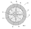
communications cable 210 according to further embodiments of the present invention will now be described. Thecommunications cable 210 includes acable jacket 212, aspacer 214, a plurality of twisted pairs ofinsulated conductors shield 216 and a plurality ofcompartments shield 216 may be omitted. Thecable jacket 212, the plurality of twisted pairs ofinsulated conductors shield 216 and the plurality ofcompartments cable jacket 10, the plurality of twisted pairs ofinsulated conductors shield 16 and the plurality ofcompartments communications cable 10. Accordingly, a detailed description thereof need not be repeated. - As shown in Figure 4, the
spacer 214 is situated within and is longitudinally coextensive with thecable jacket 212. Thespacer 214 may comprise the same materials and may be fabricated using the same fabrication techniques that were discussed in connection with thespacer 14. As illustrated in Figure 4, thespacer 214 includes a longitudinally extendingcenter portion 230 and a plurality of longitudinally extendingwall portions center portion 230. Eachindividual wall portion radial sections radial section center portion 230. As will be understood to one of skill in the art, the change in thickness of the radial sections that increase or decrease in thickness may be linear or non-linear, and may be continuous or discontinuous. In the embodiment illustrated in Figure 4, eachwall portion radial sections wall portions - As will be understood by one of skill in the art, the plurality of
radial sections wall portions radial sections - With reference to Figure 5, a
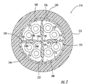
communications cable 310 according to further embodiments of the present invention will now be described. Thecommunications cable 310 includes acable jacket 312, aspacer 314, a plurality of twisted pairs ofinsulated conductors shield 316 and a plurality ofcompartments shield 316 may be omitted. Thecable jacket 312, the plurality of twisted pairs ofinsulated conductors shield 316 and the plurality ofcompartments cable jacket 10, the plurality of twisted pairs ofinsulated conductors shield 16 and the plurality ofcompartments communications cable 10. Accordingly, a detailed description thereof need not be repeated. - As shown in Figure 5, the
spacer 314 is situated within and is longitudinally coextensive with thecable jacket 312. Thespacer 314 may comprise the same materials and may be fabricated using the same fabrication techniques that were discussed in connection with thespacer 14. As illustrated in Figure 5, thespacer 314 includes a longitudinally extendingcenter portion 330 and a plurality of longitudinally extendingwall portions center portion 330. Eachindividual wall portion radial sections radial section center portion 330. As will be understood to one of skill in the art, the change in thickness of the radial sections that increase or decrease in thickness may be linear or non-linear, and may be continuous or discontinuous. - In the embodiment illustrated in Figure 5, the plurality of
radial sections wall portions wall portions - With reference to Figure 6, a
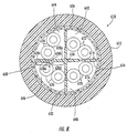
communications cable 410 according to further embodiments of the present invention will now be described. Thecommunications cable 410 includes acable jacket 412, aspacer 414, a plurality of twisted pairs ofinsulated conductors shield 416 and a plurality ofcompartments shield 416 may be omitted. Thecable jacket 412, the plurality of twisted pairs ofinsulated conductors shield 416 and the plurality ofcompartments cable jacket 10, the plurality of twisted pairs ofinsulated conductors shield 16 and the plurality ofcompartments communications cable 10. Accordingly, a detailed description thereof need not be repeated. - As shown in Figure 6, the
spacer 414 is situated within and is longitudinally coextensive with thecable jacket 412. Thespacer 414 may comprise the same materials and may be fabricated using the same fabrication techniques that were discussed in connection with thespacer 14. As illustrated in Figure 6, thespacer 414 includes a longitudinally extendingcenter portion 430 and a plurality of longitudinally extendingwall portions center portion 430. Eachindividual wall portion center portion 430, or may have a knob shaped cross-section. As will be understood to one of skill in the art, the change in thickness of the radial sections that increase or decrease in thickness may be linear or non-linear, and may be continuous or discontinuous. In the embodiment illustrated in Figure 6, eachwall portion - As will be also understood by one of skill in the art, the plurality of radial sections 438a, 438b may also be configured to produce
wall portions - With reference to Figure 7, a
communications cable 510 according to further embodiments of the present invention will now be described. Thecommunications cable 510 includes acable jacket 512, aspacer 514, a plurality of twisted pairs ofinsulated conductors shield 516 and a plurality ofcompartments shield 516 may be omitted. Thecable jacket 512, the plurality of twisted pairs ofinsulated conductors shield 516 and the plurality ofcompartments cable jacket 10, the plurality of twisted pairs ofinsulated conductors shield 16 and the plurality ofcompartments communications cable 10. Accordingly, a detailed description thereof need not be repeated. - As shown in Figure 7, the
spacer 514 is situated within and is longitudinally coextensive with thecable jacket 512. Thespacer 514 may comprise the same materials and may be fabricated using the same fabrication techniques that were discussed in connection with thespacer 14. As illustrated in Figure 7, thespacer 514 includes a longitudinally extendingcenter portion 530 and a plurality of longitudinally extendingwall portions center portion 530. Eachindividual wall portion radial sections radial section center portion 530. As will be understood to one of skill in the art, the change in thickness of the radial sections that increase or decrease in thickness may be linear or non-linear, and may be continuous or discontinuous. In the embodiment illustrated in Figure 7, eachwall portion radial sections radial section 538b is thicker than the other tworadial sections 538a, 538c thus forming a ribbed portion. Alternatively, the embodiment illustrated in Figure 7 may also be described as including tworadial sections discontinuous manner 538d with distance from thecenter portion 530 and one that decreases in thickness in adiscontinuous manner 538e with distance from thecenter portion 530, which are configured such that thewall portions - As will be understood by one of skill in the art, the width B of a ribbed portion for any one
wall portion other wall portion - With reference to Figure 8, a
communications cable 610 according to further embodiments of the present invention will now be described. Thecommunications cable 610 includes acable jacket 612, aspacer 614, a plurality of twisted pairs ofinsulated conductors shield 616 and a plurality ofcompartments shield 616 may be omitted. Thecable jacket 612, the plurality of twisted pairs ofinsulated conductors shield 616 and the plurality ofcompartments cable jacket 10, the plurality of twisted pairs ofinsulated conductors shield 16 and the plurality ofcompartments communications cable 10. Accordingly, a detailed description thereof need not be repeated. - As shown in Figure 8, the
spacer 614 is situated within and is longitudinally coextensive with thecable jacket 612. Thespacer 614 may comprise the same materials and may be fabricated using the same fabrication techniques that were discussed in connection with thespacer 14. As illustrated in Figure 8, thespacer 614 includes a longitudinally extendingcenter portion 630 and a plurality of longitudinally extendingwall portions center portion 630. Eachindividual wall portion radial sections radial section center portion 630. As will be understood to one of skill in the art, the change in thickness of the radial sections that increase or decrease in thickness may be linear or non-linear, and may be continuous or discontinuous. In the embodiment illustrated in Figure 8, eachwall portion radial sections radial section 638b is thinner than the other tworadial sections radial sections discontinuous manner 638d with distance from thecenter portion 630 and one that increases in thickness in adiscontinuous manner 638e with distance from thecenter portion 630, which are configured such that thewall portions - As will be understood by one of skill in the art, the width A of a recessed portion for any one
wall portion other wall portion - It will be understood that the various geometric shapes (e.g., sawtooth shaped, knob shaped etc.) of the wall portions of the embodiments of the present invention illustrated in Figures 1-8 may be combined. For example, the knob shaped cross-section illustrated in Figure 6 may be combined with the recessed shaped cross-section in Figure 8 to form wall portions having both a recessed portion and a knob shaped portion. It will also be understood that a conventional rip cord and/or a drain wire may be included in any of the embodiments of the present invention.
- Communications cables according to embodiments of the invention in operation may reduce, and preferably minimize, cross-talk between the twisted pairs of insulated conductors. Moreover, communications cables according to embodiments of the invention may reduce, and preferably minimize, capacitance imbalance as desired for such cables.
- The foregoing is illustrative of the present invention and is not to be construed as limiting thereof. Although a few exemplary embodiments of this invention have been described, those skilled in the art will readily appreciate that many modifications are possible in the exemplary embodiments without materially departing from the novel teachings and advantages of this invention. Accordingly, all such modifications are intended to be included within the scope of this invention as defined in the claims. It is to be understood that the foregoing is illustrative of the present invention and is not to be construed as limited to the specific embodiments disclosed, and that modifications to the disclosed embodiments, as well as other embodiments, are intended to be included within the scope of the appended claims. The invention is defined by the following claims, with equivalents of the claims to be included therein.
Claims (35)
- A communications cable comprising:a cable jacket;a spacer extending within the cable jacket, the spacer having a longitudinally extending center portion and plurality of longitudinally extending wall portions radiating from the center portion, the longitudinally extending wall portions increasing in thickness from the center portion to the cable jacket, the spacer and the cable jacket defining a plurality of compartments within the cable jacket;a shield extending between the spacer and the cable jacket; anda twisted pair of insulated conductors disposed in one of the plurality of compartments.
- A communications cable comprising:a cable jacket;a spacer extending within the cable jacket, the spacer having a longitudinally extending center portion and plurality of longitudinally extending wall portions radiating from the center portion, the longitudinally extending wall portions increasing in thickness over only a portion thereof from the center portion to the cable jacket, the spacer and the cable jacket defining a plurality of compartments within the cable jacket; anda twisted pair of insulated conductors disposed in one of the plurality of compartments.
- A communications cable comprising:a cable jacket;a spacer extending within the cable jacket, the spacer having a longitudinally extending center portion and plurality of longitudinally extending wall portions radiating from the center portion, the longitudinally extending wall portions decreasing in thickness over only a portion thereof from the center portion to the cable jacket, the spacer and the cable jacket defining a plurality of compartments within the cable jacket; anda twisted pair of insulated conductors disposed in one of the plurality of compartments.
- The communications cable according to any of the preceding claims further comprising a plurality of twisted pairs of insulated conductors disposed in respective ones of the plurality of compartments.
- The communications cable according to Claim 4 wherein each of the plurality of twisted pairs of insulated conductors has a different lay length.
- The communications cable according to Claim 4 or Claim 5 wherein the plurality of longitudinally extending wall portions are configured so as to define a plurality of compartments of a helical configuration within the cable jacket and the plurality of twisted pairs of insulated conductors located within the plurality of compartments extend helically about the longitudinal axis of the cable.
- A communications cable comprising:a cable jacket;a spacer extending within said cable jacket, the spacer having a longitudinally extending center portion and plurality of longitudinally extending wall portions radiating from said center portion, the longitudinally extending wall portions having a first radial section that increases in thickness with distance from the center portion, and a second radial section that decreases in thickness with distance from the center portion, the spacer and the cable jacket defining a plurality of compartments within the cable jacket; anda twisted pair of insulated conductors disposed in at least one of the compartments.
- The communications cable according to Claim 7 wherein the first radial section is located between the center portion and the second radial section.
- The communications cable according to Claim 7 or Claim 8 wherein the second radial section is located between the center portion and the first radial section.
- The communications cable according to any of Claims 7 to 9 wherein the first radial section and the second radial section are configured such that the plurality of longitudinally extending wall portions have a convex shaped cross-section.
- The communications cable according to any of claims 7 to 9 wherein the first radial section and the second radial section are configured such that the plurality of longitudinally extending wall portions have a concave shaped cross-section.
- The communications cable according to Claim 10 or 11 wherein the shaped cross-section is arcuate.
- The communications cable according to any of Claims 10 to 12 wherein the shaped cross-section comprises a plurality of faces.
- The communications cable according to any of Claims 7 to 13 wherein the first radial section and second radial section are configured such that the plurality of longitudinally extending wall portions have a recessed portion.
- The communications cable according to any of Claims 7 to 13 wherein the first radial section and second radial section are configured such that the plurality of longitudinally extending wall portions have a ribbed portion.
- The communications cable according to any of Claims 7 to 13 wherein the first radial section and the second radial section are configured such that the plurality of longitudinally extending wall portions have a sawtooth shaped cross-section.
- A communications cable comprising:a cable jacket;a spacer extending within said cable jacket, the spacer having a longitudinally extending center portion and plurality of longitudinally extending wall portions radiating from said center portion, the longitudinally extending wall portions including a first section having a first thickness, a second section having a second thickness and a third section having a third thickness, the third thickness being different from the first and second thickness, the third section located between the first section and the second section, the spacer and the cable jacket defining a plurality of compartments within the cable jacket; anda twisted pair of insulated conductors disposed in at least one of the compartments.
- The communications cable of Claim 17 wherein the first, second and third thickness are different from one another.
- The communications cable of Claim 17 wherein the first thickness and the second thickness are the same and the third thickness is different from the first thickness.
- The communications cable of Claim 19 wherein the third thickness is greater than the first thickness.
- The communications cable of Claim 19 wherein the third thickness is less than the first thickness.
- A communications cable comprising:a cable jacket;a spacer extending within said cable jacket, the spacer having a longitudinally extending center portion and plurality of longitudinally extending wall portions radiating from said center portion, the longitudinally extending wall portions having a sawtooth shaped cross-section including a plurality of teeth, each tooth having a tooth height and a tooth spacing, the spacer and the cable jacket defining a plurality of compartments within the cable jacket; anda twisted pair of insulated conductors disposed in at least one of the compartments.
- The communications table according to Claim 22 wherein each tooth height is the same.
- The communications cable according to Claim 22 wherein at least two tooth heights are different.
- The communications cable according to any of Claims 22 to 24 wherein each tooth spacing is the same.
- The communications cable according to any of Claims 22 to 24 wherein at least two tooth spacings are different.
- The communications cable according to Claim 22 wherein at least two tooth heights are different and at least two tooth spacings are different.
- A communications cable comprising:a cable jacket;a spacer extending within said cable jacket, the spacer having a longitudinally extending center portion and plurality of longitudinally extending wall portions radiating from said center portion, the longitudinally extending wall portions including a knob shaped cross-section, the spacer and the cable jacket defining a plurality of compartments within the cable jacket; anda twisted pair of insulated conductors disposed in at least one of the compartments.
- The communications cable according to Claim 28 wherein the knob shaped cross-section is a half knob.
- The communications cable according to Claim 28 wherein the knob shaped cross-section is a whole knob.
- The communications cable according to any of Claims 28 to 39 wherein the longitudinally extending wall portions includes a plurality of knob shaped cross-sections.
- A communications cable comprising:a cable jacket;a spacer extending within said cable jacket, the spacer having a longitudinally extending center portion and plurality of longitudinally extending wall portions radiating from said center portion, the longitudinally extending wall portions having a convex shaped cross-section, the spacer and the cable jacket defining a plurality of compartments within the cable jacket; anda twisted pair of insulated conductors disposed in at least one of the compartments.
- A communications cable comprising:a cable jacket;a spacer extending within said cable jacket, the spacer having a longitudinally extending center portion and plurality of longitudinally extending wall portions radiating from said center portion, the longitudinally extending wall portions having a concave shaped cross-section, the spacer and the cable jacket defining a plurality of compartments within the cable jacket; anda twisted pair of insulated conductors disposed in at least one of the compartments.
- The communication cable of Claim 32 or Claim 33 wherein the convex shaped cross-section is arcuate.
- The communications cable of any of Claims 32 to 34 where the convex shaped cross-section comprises a plurality of faces.
Applications Claiming Priority (2)
| Application Number | Priority Date | Filing Date | Title |
|---|---|---|---|
| US09/591,349 US6800811B1 (en) | 2000-06-09 | 2000-06-09 | Communications cables with isolators |
| US591349 | 2000-06-09 |
Publications (3)
| Publication Number | Publication Date |
|---|---|
| EP1162632A2 true EP1162632A2 (en) | 2001-12-12 |
| EP1162632A3 EP1162632A3 (en) | 2003-01-02 |
| EP1162632B1 EP1162632B1 (en) | 2009-07-15 |
Family
ID=24366139
Family Applications (1)
| Application Number | Title | Priority Date | Filing Date |
|---|---|---|---|
| EP01304730A Expired - Lifetime EP1162632B1 (en) | 2000-06-09 | 2001-05-24 | Communications cables with isolators |
Country Status (6)
| Country | Link |
|---|---|
| US (1) | US6800811B1 (en) |
| EP (1) | EP1162632B1 (en) |
| BR (1) | BR0102311B1 (en) |
| CA (1) | CA2349327C (en) |
| DE (1) | DE60139227D1 (en) |
| MX (1) | MXPA01005852A (en) |
Cited By (19)
| Publication number | Priority date | Publication date | Assignee | Title |
|---|---|---|---|---|
| WO2003021607A1 (en) * | 2001-08-25 | 2003-03-13 | Cable Components Group | High performace support-separators for communications cables |
| WO2003077265A1 (en) * | 2002-03-13 | 2003-09-18 | Nordx/Cdt, Inc. | Twisted pair cable with cable separator |
| US6818832B2 (en) * | 2002-02-26 | 2004-11-16 | Commscope Solutions Properties, Llc | Network cable with elliptical crossweb fin structure |
| WO2006025812A1 (en) * | 2004-07-16 | 2006-03-09 | Charles Glew | Hollow support separators for communications cable |
| US7154043B2 (en) * | 1997-04-22 | 2006-12-26 | Belden Technologies, Inc. | Data cable with cross-twist cabled core profile |
| WO2007026994A1 (en) * | 2005-08-30 | 2007-03-08 | Ls Cable Ltd. | Communication cable having spacer integrated with separator therein |
| US7196272B2 (en) * | 2002-05-01 | 2007-03-27 | Cable Components Group, Llc. | High performance support-separators for communications cables |
| US7208683B2 (en) * | 2005-01-28 | 2007-04-24 | Belden Technologies, Inc. | Data cable for mechanically dynamic environments |
| US7214882B2 (en) * | 2001-02-28 | 2007-05-08 | Prysmian Cavi E Sistemi Energia S.R.L. | Communications cable, method and plant for manufacturing the same |
| US7241953B2 (en) * | 2003-04-15 | 2007-07-10 | Cable Components Group, Llc. | Support-separators for high performance communications cable with optional hollow tubes for; blown optical fiber, coaxial, and/or twisted pair conductors |
| US7390971B2 (en) | 2005-04-29 | 2008-06-24 | Nexans | Unsheilded twisted pair cable and method for manufacturing the same |
| US7405360B2 (en) | 1997-04-22 | 2008-07-29 | Belden Technologies, Inc. | Data cable with cross-twist cabled core profile |
| US7449638B2 (en) | 2005-12-09 | 2008-11-11 | Belden Technologies, Inc. | Twisted pair cable having improved crosstalk isolation |
| US7663061B2 (en) | 1996-04-09 | 2010-02-16 | Belden Technologies, Inc. | High performance data cable |
| US7897875B2 (en) | 2007-11-19 | 2011-03-01 | Belden Inc. | Separator spline and cables using same |
| US8030571B2 (en) | 2006-03-06 | 2011-10-04 | Belden Inc. | Web for separating conductors in a communication cable |
| US20110266052A1 (en) * | 2004-11-06 | 2011-11-03 | Cable Components Group, Llc | High performance support-separators for communications cables providing shielding for minimizing alien crosstalk |
| WO2015166324A1 (en) * | 2014-05-01 | 2015-11-05 | Nexans | Profiled cross filler in lan cables |
| US9711261B2 (en) | 2012-03-13 | 2017-07-18 | Cable Components Group, Llc | Compositions, methods, and devices providing shielding in communications cables |
Families Citing this family (45)
| Publication number | Priority date | Publication date | Assignee | Title |
|---|---|---|---|---|
| US6074503A (en) * | 1997-04-22 | 2000-06-13 | Cable Design Technologies, Inc. | Making enhanced data cable with cross-twist cabled core profile |
| AU5191801A (en) * | 2001-06-14 | 2002-12-19 | Pirelli Cables Australia Limited | Communications cable provided with a crosstalk barrier for use at high transmission frequencies |
| US7214884B2 (en) | 2003-10-31 | 2007-05-08 | Adc Incorporated | Cable with offset filler |
| US7115815B2 (en) * | 2003-10-31 | 2006-10-03 | Adc Telecommunications, Inc. | Cable utilizing varying lay length mechanisms to minimize alien crosstalk |
| US7838773B2 (en) * | 2004-11-15 | 2010-11-23 | Belden Cdt (Canada) Inc. | High performance telecommunications cable |
| WO2006088852A1 (en) * | 2005-02-14 | 2006-08-24 | Panduit Corp. | Enhanced communication cable systems and methods |
| US20060237221A1 (en) * | 2005-04-25 | 2006-10-26 | Cable Components Group, Llc. | High performance, multi-media communication cable support-separators with sphere or loop like ends for eccentric or concentric cables |
| US7473850B2 (en) * | 2005-04-25 | 2009-01-06 | Cable Components Group | High performance, multi-media cable support-separator facilitating insertion and removal of conductive media |
| US7465879B2 (en) * | 2005-04-25 | 2008-12-16 | Cable Components Group | Concentric-eccentric high performance, multi-media communications cables and cable support-separators utilizing roll-up designs |
| US7473849B2 (en) * | 2005-04-25 | 2009-01-06 | Cable Components Group | Variable diameter conduit tubes for high performance, multi-media communication cable |
| US7259993B2 (en) * | 2005-06-03 | 2007-08-21 | Infineon Technologies Ag | Reference scheme for a non-volatile semiconductor memory device |
| US7173189B1 (en) * | 2005-11-04 | 2007-02-06 | Adc Telecommunications, Inc. | Concentric multi-pair cable with filler |
| US7145080B1 (en) | 2005-11-08 | 2006-12-05 | Hitachi Cable Manchester, Inc. | Off-set communications cable |
| US7271342B2 (en) * | 2005-12-22 | 2007-09-18 | Adc Telecommunications, Inc. | Cable with twisted pair centering arrangement |
| US7329814B2 (en) * | 2005-12-29 | 2008-02-12 | Capricorn Audio Technologies Ltd | Electrical cable |
| US7271344B1 (en) | 2006-03-09 | 2007-09-18 | Adc Telecommunications, Inc. | Multi-pair cable with channeled jackets |
| US7375284B2 (en) * | 2006-06-21 | 2008-05-20 | Adc Telecommunications, Inc. | Multi-pair cable with varying lay length |
| US7550674B2 (en) * | 2007-02-22 | 2009-06-23 | Nexans | UTP cable |
| US7737358B2 (en) * | 2007-04-12 | 2010-06-15 | Commscope, Inc. Of North Carolina | Data transmission cable pairs and cables and methods for forming the same |
| EP2065156A1 (en) * | 2007-11-29 | 2009-06-03 | Nexans | Method for producing a moulded product from polytetrafluorothylene foam |
| US20090191751A1 (en) * | 2008-01-28 | 2009-07-30 | Lockheed Martin Corporation | Coaxial cable alignment enhancer for use within coaxial cable assemblies so as to ensure the proper coaxial disposition of the coaxial cable contact members of coaxial cable electrical connectors |
| KR101070501B1 (en) * | 2008-09-25 | 2011-10-05 | 엘에스전선 주식회사 | A Data Communication Cable |
| MX2011007959A (en) * | 2009-01-30 | 2011-08-17 | Gen Cable Technologies Corp | Separator for communication cable with geometric features. |
| US8319104B2 (en) | 2009-02-11 | 2012-11-27 | General Cable Technologies Corporation | Separator for communication cable with shaped ends |
| US20110011638A1 (en) * | 2009-07-16 | 2011-01-20 | Paul Gemme | Shielding tape with edge indicator |
| US9728304B2 (en) * | 2009-07-16 | 2017-08-08 | Pct International, Inc. | Shielding tape with multiple foil layers |
| WO2011112704A2 (en) * | 2010-03-12 | 2011-09-15 | General Cable Technologies Corporation | Insulation with micro oxide particles and cable using the same |
| US8882520B2 (en) | 2010-05-21 | 2014-11-11 | Pct International, Inc. | Connector with a locking mechanism and a movable collet |
| US8579658B2 (en) | 2010-08-20 | 2013-11-12 | Timothy L. Youtsey | Coaxial cable connectors with washers for preventing separation of mated connectors |
| US9028276B2 (en) | 2011-12-06 | 2015-05-12 | Pct International, Inc. | Coaxial cable continuity device |
| ES2548704T3 (en) * | 2012-04-27 | 2015-10-20 | Draka Comteq Bv | Electric cable, in particular a data transmission cable, equipped with a multilayer band type protection sheet |
| US9349507B2 (en) * | 2012-11-06 | 2016-05-24 | Apple Inc. | Reducing signal loss in cables |
| JP6149763B2 (en) * | 2014-03-03 | 2017-06-21 | 住友電装株式会社 | Shield conductive path |
| US10031301B2 (en) * | 2014-11-07 | 2018-07-24 | Cable Components Group, Llc | Compositions for compounding, extrusion, and melt processing of foamable and cellular polymers |
| WO2016073862A2 (en) | 2014-11-07 | 2016-05-12 | Cable Components Group, Llc | Compositions for compounding, extrusion and melt processing of foamable and cellular halogen-free polymers |
| US10121571B1 (en) * | 2016-08-31 | 2018-11-06 | Superior Essex International LP | Communications cables incorporating separator structures |
| US10276281B1 (en) | 2016-11-08 | 2019-04-30 | Superior Essex International LP | Communication cables with twisted tape separators |
| US10068685B1 (en) | 2016-11-08 | 2018-09-04 | Superior Essex International LP | Communication cables with separators having alternating projections |
| US10438726B1 (en) | 2017-06-16 | 2019-10-08 | Superior Essex International LP | Communication cables incorporating separators with longitudinally spaced radial ridges |
| US10059278B1 (en) | 2017-07-18 | 2018-08-28 | Paul Stotts | System and method for retrofitting vehicles with onboard monitoring equipment |
| US10553333B2 (en) * | 2017-09-28 | 2020-02-04 | Sterlite Technologies Limited | I-shaped filler |
| US11152137B2 (en) * | 2018-02-26 | 2021-10-19 | Panduit Corp. | Communications cable with triboelectric protection |
| US11410800B2 (en) * | 2018-07-31 | 2022-08-09 | Commscope Technologies Llc | Low cost extrudable isolator from slit-tape |
| EP3895187A4 (en) * | 2018-11-22 | 2023-02-08 | Sterlite Technologies Ltd | Telecommunications cable with twin jacket and barrier |
| CN109887660A (en) * | 2019-02-28 | 2019-06-14 | 华迅工业(苏州)有限公司 | A kind of high fire-retardance rail traffic network cable |
Citations (5)
| Publication number | Priority date | Publication date | Assignee | Title |
|---|---|---|---|---|
| JPH04332406A (en) * | 1990-11-16 | 1992-11-19 | Oki Densen Kk | Spacer type flexible shield cable and manufacture thereof |
| US5969295A (en) * | 1998-01-09 | 1999-10-19 | Commscope, Inc. Of North Carolina | Twisted pair communications cable |
| WO2001054139A1 (en) * | 1999-12-02 | 2001-07-26 | Belden Wire And Cable Company | A cable channel filler and cable containing the same |
| US6297454B1 (en) * | 1999-12-02 | 2001-10-02 | Belden Wire & Cable Company | Cable separator spline |
| US6342678B1 (en) * | 1998-03-12 | 2002-01-29 | Nexans | Low-crosstalk flexible cable |
Family Cites Families (32)
| Publication number | Priority date | Publication date | Assignee | Title |
|---|---|---|---|---|
| US483285A (en) | 1892-09-27 | auilleaume | ||
| US1977209A (en) | 1930-12-09 | 1934-10-16 | Macintosh Cable Company Ltd | Electric cable |
| GB505761A (en) | 1937-10-14 | 1939-05-15 | John Cuthbert Swallow | Improvements in and relating to the manufacture of electric cables |
| US2340926A (en) | 1940-09-05 | 1944-02-08 | Detroit Macoid Corp | Plastic conduit |
| GB1152297A (en) | 1968-02-22 | 1969-05-14 | Standard Telephones Cables Ltd | Improvements in Coaxial Cables |
| US3927247A (en) | 1968-10-07 | 1975-12-16 | Belden Corp | Shielded coaxial cable |
| DE1813397A1 (en) | 1968-12-07 | 1970-06-18 | Kabel Metallwerke Ghh | Arrangement for holding one or more superconductive conductor strings inside a deeply cooled cable |
| US3621118A (en) | 1970-07-31 | 1971-11-16 | Anaconda Wire & Cable Co | Power cable for portable machines |
| GB1448793A (en) | 1974-05-31 | 1976-09-08 | Post Office | Optical cables |
| DE2459844A1 (en) | 1974-12-18 | 1976-07-01 | Felten & Guilleaume Kabelwerk | Multi-core telephone cable - has profiled strand with grooves and upstanding ribs between which are secured metal cores |
| US4132854A (en) | 1977-08-29 | 1979-01-02 | Westinghouse Electric Corp. | Multiple conductor gas insulated transmission line |
| US4729409A (en) | 1980-10-07 | 1988-03-08 | Borg-Warner Corporation | Hexagonal underground electrical conduit |
| US4374881A (en) | 1981-03-24 | 1983-02-22 | Eaton Corporation | Heat recoverable connector |
| GB8417774D0 (en) | 1984-07-12 | 1984-08-15 | Telephone Cables Ltd | Cable ducting |
| US4683349A (en) | 1984-11-29 | 1987-07-28 | Norichika Takebe | Elastic electric cable |
| US4778246A (en) | 1985-05-15 | 1988-10-18 | Acco Babcock Industries, Inc. | High tensile strength compacted towing cable with signal transmission element and method of making the same |
| SU1343447A1 (en) | 1985-05-16 | 1987-10-07 | Всесоюзный Научно-Исследовательский Институт Железнодорожного Транспорта | Combined balanced communication cable |
| US4731506A (en) | 1986-10-29 | 1988-03-15 | Noel Lee | Signal cable assembly |
| US5227585A (en) | 1990-08-30 | 1993-07-13 | Sergio Zen | System of tubes and connection blocks to contain electric telephone and television cables |
| DE4039275A1 (en) | 1990-09-24 | 1992-04-02 | Vogelsang Ernst Gmbh Co Kg | CABLE GUIDE TUBE BUNDLE FROM A MULTIPLE PLASTIC PIPES |
| US5132488A (en) | 1991-02-21 | 1992-07-21 | Northern Telecom Limited | Electrical telecommunications cable |
| JPH05101711A (en) | 1991-10-08 | 1993-04-23 | Oki Densen Kk | Low electrostatic capacity type insulated wire |
| US5305797A (en) | 1993-05-10 | 1994-04-26 | Roy Sr John D | Compartmented conduit tube construction |
| US5493071A (en) | 1994-11-10 | 1996-02-20 | Berk-Tek, Inc. | Communication cable for use in a plenum |
| US5541361A (en) | 1994-12-20 | 1996-07-30 | At&T Corp. | Indoor communication cable |
| US5619016A (en) | 1995-01-31 | 1997-04-08 | Alcatel Na Cable Systems, Inc. | Communication cable for use in a plenum |
| US5574250A (en) | 1995-02-03 | 1996-11-12 | W. L. Gore & Associates, Inc. | Multiple differential pair cable |
| US5661836A (en) | 1995-02-20 | 1997-08-26 | Sumitomo Electric Industries, Ltd. | Optical cable and manufacturing method thereof |
| FR2738947B1 (en) | 1995-09-15 | 1997-10-17 | Filotex Sa | MULTI-PAIR CABLE, SHIELDED PER PAIR AND EASY TO CONNECT |
| US5789711A (en) | 1996-04-09 | 1998-08-04 | Belden Wire & Cable Company | High-performance data cable |
| US6074503A (en) | 1997-04-22 | 2000-06-13 | Cable Design Technologies, Inc. | Making enhanced data cable with cross-twist cabled core profile |
| US5950393A (en) * | 1998-07-27 | 1999-09-14 | Surface Technologies, Inc. | Non-corrosive reinforcing member having bendable flanges |
-
2000
- 2000-06-09 US US09/591,349 patent/US6800811B1/en not_active Expired - Fee Related
-
2001
- 2001-05-24 EP EP01304730A patent/EP1162632B1/en not_active Expired - Lifetime
- 2001-05-24 DE DE60139227T patent/DE60139227D1/en not_active Expired - Lifetime
- 2001-05-31 CA CA002349327A patent/CA2349327C/en not_active Expired - Fee Related
- 2001-06-07 BR BRPI0102311-0A patent/BR0102311B1/en not_active IP Right Cessation
- 2001-06-08 MX MXPA01005852A patent/MXPA01005852A/en active IP Right Grant
Patent Citations (5)
| Publication number | Priority date | Publication date | Assignee | Title |
|---|---|---|---|---|
| JPH04332406A (en) * | 1990-11-16 | 1992-11-19 | Oki Densen Kk | Spacer type flexible shield cable and manufacture thereof |
| US5969295A (en) * | 1998-01-09 | 1999-10-19 | Commscope, Inc. Of North Carolina | Twisted pair communications cable |
| US6342678B1 (en) * | 1998-03-12 | 2002-01-29 | Nexans | Low-crosstalk flexible cable |
| WO2001054139A1 (en) * | 1999-12-02 | 2001-07-26 | Belden Wire And Cable Company | A cable channel filler and cable containing the same |
| US6297454B1 (en) * | 1999-12-02 | 2001-10-02 | Belden Wire & Cable Company | Cable separator spline |
Non-Patent Citations (1)
| Title |
|---|
| PATENT ABSTRACTS OF JAPAN vol. 017, no. 178 (E-1347), 7 April 1993 (1993-04-07) & JP 04 332406 A (OKI DENSEN KK), 19 November 1992 (1992-11-19) * |
Cited By (34)
| Publication number | Priority date | Publication date | Assignee | Title |
|---|---|---|---|---|
| US8497428B2 (en) | 1996-04-09 | 2013-07-30 | Belden Inc. | High performance data cable |
| US7663061B2 (en) | 1996-04-09 | 2010-02-16 | Belden Technologies, Inc. | High performance data cable |
| US7977575B2 (en) | 1996-04-09 | 2011-07-12 | Belden Inc. | High performance data cable |
| US8536455B2 (en) | 1996-04-09 | 2013-09-17 | Belden Inc. | High performance data cable |
| US7696438B2 (en) | 1997-04-22 | 2010-04-13 | Belden Technologies, Inc. | Data cable with cross-twist cabled core profile |
| US7534964B2 (en) | 1997-04-22 | 2009-05-19 | Belden Technologies, Inc. | Data cable with cross-twist cabled core profile |
| US7154043B2 (en) * | 1997-04-22 | 2006-12-26 | Belden Technologies, Inc. | Data cable with cross-twist cabled core profile |
| US7405360B2 (en) | 1997-04-22 | 2008-07-29 | Belden Technologies, Inc. | Data cable with cross-twist cabled core profile |
| US7964797B2 (en) | 1997-04-22 | 2011-06-21 | Belden Inc. | Data cable with striated jacket |
| US7214882B2 (en) * | 2001-02-28 | 2007-05-08 | Prysmian Cavi E Sistemi Energia S.R.L. | Communications cable, method and plant for manufacturing the same |
| WO2003021607A1 (en) * | 2001-08-25 | 2003-03-13 | Cable Components Group | High performace support-separators for communications cables |
| US7098405B2 (en) * | 2001-08-25 | 2006-08-29 | Glew Charles A | High performance support-separator for communications cables |
| US6818832B2 (en) * | 2002-02-26 | 2004-11-16 | Commscope Solutions Properties, Llc | Network cable with elliptical crossweb fin structure |
| US7196271B2 (en) | 2002-03-13 | 2007-03-27 | Belden Cdt (Canada) Inc. | Twisted pair cable with cable separator |
| WO2003077265A1 (en) * | 2002-03-13 | 2003-09-18 | Nordx/Cdt, Inc. | Twisted pair cable with cable separator |
| US7196272B2 (en) * | 2002-05-01 | 2007-03-27 | Cable Components Group, Llc. | High performance support-separators for communications cables |
| US7399927B2 (en) * | 2002-05-01 | 2008-07-15 | Cable Components Group, Llc | High performance support-separators for communications cables |
| US7241953B2 (en) * | 2003-04-15 | 2007-07-10 | Cable Components Group, Llc. | Support-separators for high performance communications cable with optional hollow tubes for; blown optical fiber, coaxial, and/or twisted pair conductors |
| US7432447B2 (en) * | 2003-04-15 | 2008-10-07 | Cable Components Group, Llc | Support separators for high performance communications cable with optional hollow tubes for; blown optical fiber, coaxial, and/or twisted pair conductors |
| WO2006025812A1 (en) * | 2004-07-16 | 2006-03-09 | Charles Glew | Hollow support separators for communications cable |
| US20110266052A1 (en) * | 2004-11-06 | 2011-11-03 | Cable Components Group, Llc | High performance support-separators for communications cables providing shielding for minimizing alien crosstalk |
| US10204719B2 (en) | 2004-11-06 | 2019-02-12 | Cable Components Group, Llc | High performance support-separators for communications cables providing shielding for minimizing alien crosstalk |
| US10204720B2 (en) | 2004-11-06 | 2019-02-12 | Cable Components Group, Llc | High performance support-separators for communications cables providing shielding for minimizing alien crosstalk |
| US9245669B2 (en) * | 2004-11-06 | 2016-01-26 | Cable Components Group, Llc | High performance support-separators for communications cables providing shielding for minimizing alien crosstalk |
| US7208683B2 (en) * | 2005-01-28 | 2007-04-24 | Belden Technologies, Inc. | Data cable for mechanically dynamic environments |
| US7390971B2 (en) | 2005-04-29 | 2008-06-24 | Nexans | Unsheilded twisted pair cable and method for manufacturing the same |
| WO2007026994A1 (en) * | 2005-08-30 | 2007-03-08 | Ls Cable Ltd. | Communication cable having spacer integrated with separator therein |
| US8198536B2 (en) | 2005-12-09 | 2012-06-12 | Belden Inc. | Twisted pair cable having improved crosstalk isolation |
| US7449638B2 (en) | 2005-12-09 | 2008-11-11 | Belden Technologies, Inc. | Twisted pair cable having improved crosstalk isolation |
| US8030571B2 (en) | 2006-03-06 | 2011-10-04 | Belden Inc. | Web for separating conductors in a communication cable |
| US7897875B2 (en) | 2007-11-19 | 2011-03-01 | Belden Inc. | Separator spline and cables using same |
| US9711261B2 (en) | 2012-03-13 | 2017-07-18 | Cable Components Group, Llc | Compositions, methods, and devices providing shielding in communications cables |
| US9875825B2 (en) | 2012-03-13 | 2018-01-23 | Cable Components Group, Llc | Compositions, methods and devices providing shielding in communications cables |
| WO2015166324A1 (en) * | 2014-05-01 | 2015-11-05 | Nexans | Profiled cross filler in lan cables |
Also Published As
| Publication number | Publication date |
|---|---|
| US6800811B1 (en) | 2004-10-05 |
| CA2349327A1 (en) | 2001-12-09 |
| EP1162632B1 (en) | 2009-07-15 |
| BR0102311B1 (en) | 2010-09-21 |
| EP1162632A3 (en) | 2003-01-02 |
| MXPA01005852A (en) | 2004-11-10 |
| DE60139227D1 (en) | 2009-08-27 |
| BR0102311A (en) | 2002-07-23 |
| CA2349327C (en) | 2008-05-20 |
Similar Documents
| Publication | Publication Date | Title |
|---|---|---|
| CA2349327C (en) | Communications cable with isolators | |
| US5969295A (en) | Twisted pair communications cable | |
| JP4485130B2 (en) | Communication cable with insulated conductor | |
| US7358436B2 (en) | Dual-insulated, fixed together pair of conductors | |
| EP1157393B1 (en) | Multi-pair data cable with configurable core filling and pair separation | |
| EP1085530B1 (en) | Electrical cable and method of making an electrical cable | |
| EP1683165B1 (en) | Data cable with cross-twist cabled core profile | |
| US7317163B2 (en) | Reduced alien crosstalk electrical cable with filler element | |
| US7534964B2 (en) | Data cable with cross-twist cabled core profile | |
| US20030106704A1 (en) | Electrical cable apparatus | |
| US7238885B2 (en) | Reduced alien crosstalk electrical cable with filler element | |
| WO2004107361A1 (en) | Multi-pair data cable with configurable core filing and pair separation | |
| KR20010072280A (en) | Cable with twisting filler | |
| WO1994016451A1 (en) | Time-matched multivalent electrical signal cables | |
| WO2006065414A2 (en) | Reduced alien crosstalk electrical cable with filler element |
Legal Events
| Date | Code | Title | Description |
|---|---|---|---|
| PUAI | Public reference made under article 153(3) epc to a published international application that has entered the european phase |
Free format text: ORIGINAL CODE: 0009012 |
|
| AK | Designated contracting states |
Kind code of ref document: A2 Designated state(s): AT BE CH CY DE DK ES FI FR GB GR IE IT LI LU MC NL PT SE TR |
|
| AX | Request for extension of the european patent |
Free format text: AL;LT;LV;MK;RO;SI |
|
| PUAL | Search report despatched |
Free format text: ORIGINAL CODE: 0009013 |
|
| AK | Designated contracting states |
Kind code of ref document: A3 Designated state(s): AT BE CH CY DE DK ES FI FR GB GR IE IT LI LU MC NL PT SE TR |
|
| AX | Request for extension of the european patent |
Free format text: AL;LT;LV;MK;RO;SI |
|
| 17P | Request for examination filed |
Effective date: 20030224 |
|
| AKX | Designation fees paid |
Designated state(s): AT BE CH CY DE DK ES FI FR GB GR IE IT LI LU MC NL PT SE TR |
|
| 17Q | First examination report despatched |
Effective date: 20071109 |
|
| GRAP | Despatch of communication of intention to grant a patent |
Free format text: ORIGINAL CODE: EPIDOSNIGR1 |
|
| GRAS | Grant fee paid |
Free format text: ORIGINAL CODE: EPIDOSNIGR3 |
|
| GRAA | (expected) grant |
Free format text: ORIGINAL CODE: 0009210 |
|
| AK | Designated contracting states |
Kind code of ref document: B1 Designated state(s): AT BE CH CY DE DK ES FI FR GB GR IE IT LI LU MC NL PT SE TR |
|
| REG | Reference to a national code |
Ref country code: CH Ref legal event code: EP Ref country code: GB Ref legal event code: FG4D |
|
| REG | Reference to a national code |
Ref country code: IE Ref legal event code: FG4D |
|
| REF | Corresponds to: |
Ref document number: 60139227 Country of ref document: DE Date of ref document: 20090827 Kind code of ref document: P |
|
| PG25 | Lapsed in a contracting state [announced via postgrant information from national office to epo] |
Ref country code: AT Free format text: LAPSE BECAUSE OF FAILURE TO SUBMIT A TRANSLATION OF THE DESCRIPTION OR TO PAY THE FEE WITHIN THE PRESCRIBED TIME-LIMIT Effective date: 20090715 Ref country code: FI Free format text: LAPSE BECAUSE OF FAILURE TO SUBMIT A TRANSLATION OF THE DESCRIPTION OR TO PAY THE FEE WITHIN THE PRESCRIBED TIME-LIMIT Effective date: 20090715 Ref country code: SE Free format text: LAPSE BECAUSE OF FAILURE TO SUBMIT A TRANSLATION OF THE DESCRIPTION OR TO PAY THE FEE WITHIN THE PRESCRIBED TIME-LIMIT Effective date: 20090715 Ref country code: ES Free format text: LAPSE BECAUSE OF FAILURE TO SUBMIT A TRANSLATION OF THE DESCRIPTION OR TO PAY THE FEE WITHIN THE PRESCRIBED TIME-LIMIT Effective date: 20091026 |
|
| PG25 | Lapsed in a contracting state [announced via postgrant information from national office to epo] |
Ref country code: PT Free format text: LAPSE BECAUSE OF FAILURE TO SUBMIT A TRANSLATION OF THE DESCRIPTION OR TO PAY THE FEE WITHIN THE PRESCRIBED TIME-LIMIT Effective date: 20091115 |
|
| PG25 | Lapsed in a contracting state [announced via postgrant information from national office to epo] |
Ref country code: DK Free format text: LAPSE BECAUSE OF FAILURE TO SUBMIT A TRANSLATION OF THE DESCRIPTION OR TO PAY THE FEE WITHIN THE PRESCRIBED TIME-LIMIT Effective date: 20090715 |
|
| PLBE | No opposition filed within time limit |
Free format text: ORIGINAL CODE: 0009261 |
|
| STAA | Information on the status of an ep patent application or granted ep patent |
Free format text: STATUS: NO OPPOSITION FILED WITHIN TIME LIMIT |
|
| PG25 | Lapsed in a contracting state [announced via postgrant information from national office to epo] |
Ref country code: BE Free format text: LAPSE BECAUSE OF FAILURE TO SUBMIT A TRANSLATION OF THE DESCRIPTION OR TO PAY THE FEE WITHIN THE PRESCRIBED TIME-LIMIT Effective date: 20090715 |
|
| 26N | No opposition filed |
Effective date: 20100416 |
|
| PGFP | Annual fee paid to national office [announced via postgrant information from national office to epo] |
Ref country code: NL Payment date: 20100524 Year of fee payment: 10 |
|
| PG25 | Lapsed in a contracting state [announced via postgrant information from national office to epo] |
Ref country code: GR Free format text: LAPSE BECAUSE OF FAILURE TO SUBMIT A TRANSLATION OF THE DESCRIPTION OR TO PAY THE FEE WITHIN THE PRESCRIBED TIME-LIMIT Effective date: 20091016 |
|
| PG25 | Lapsed in a contracting state [announced via postgrant information from national office to epo] |
Ref country code: MC Free format text: LAPSE BECAUSE OF NON-PAYMENT OF DUE FEES Effective date: 20100531 |
|
| REG | Reference to a national code |
Ref country code: CH Ref legal event code: PL |
|
| PG25 | Lapsed in a contracting state [announced via postgrant information from national office to epo] |
Ref country code: CH Free format text: LAPSE BECAUSE OF NON-PAYMENT OF DUE FEES Effective date: 20100531 Ref country code: LI Free format text: LAPSE BECAUSE OF NON-PAYMENT OF DUE FEES Effective date: 20100531 |
|
| PG25 | Lapsed in a contracting state [announced via postgrant information from national office to epo] |
Ref country code: IT Free format text: LAPSE BECAUSE OF FAILURE TO SUBMIT A TRANSLATION OF THE DESCRIPTION OR TO PAY THE FEE WITHIN THE PRESCRIBED TIME-LIMIT Effective date: 20090715 |
|
| PG25 | Lapsed in a contracting state [announced via postgrant information from national office to epo] |
Ref country code: IE Free format text: LAPSE BECAUSE OF NON-PAYMENT OF DUE FEES Effective date: 20100524 |
|
| REG | Reference to a national code |
Ref country code: NL Ref legal event code: V1 Effective date: 20111201 |
|
| PG25 | Lapsed in a contracting state [announced via postgrant information from national office to epo] |
Ref country code: NL Free format text: LAPSE BECAUSE OF NON-PAYMENT OF DUE FEES Effective date: 20111201 |
|
| PG25 | Lapsed in a contracting state [announced via postgrant information from national office to epo] |
Ref country code: CY Free format text: LAPSE BECAUSE OF FAILURE TO SUBMIT A TRANSLATION OF THE DESCRIPTION OR TO PAY THE FEE WITHIN THE PRESCRIBED TIME-LIMIT Effective date: 20090715 |
|
| PG25 | Lapsed in a contracting state [announced via postgrant information from national office to epo] |
Ref country code: LU Free format text: LAPSE BECAUSE OF NON-PAYMENT OF DUE FEES Effective date: 20100524 |
|
| PG25 | Lapsed in a contracting state [announced via postgrant information from national office to epo] |
Ref country code: TR Free format text: LAPSE BECAUSE OF FAILURE TO SUBMIT A TRANSLATION OF THE DESCRIPTION OR TO PAY THE FEE WITHIN THE PRESCRIBED TIME-LIMIT Effective date: 20090715 |
|
| PGFP | Annual fee paid to national office [announced via postgrant information from national office to epo] |
Ref country code: FR Payment date: 20140519 Year of fee payment: 14 Ref country code: DE Payment date: 20140529 Year of fee payment: 14 |
|
| PGFP | Annual fee paid to national office [announced via postgrant information from national office to epo] |
Ref country code: GB Payment date: 20150527 Year of fee payment: 15 |
|
| REG | Reference to a national code |
Ref country code: DE Ref legal event code: R119 Ref document number: 60139227 Country of ref document: DE |
|
| REG | Reference to a national code |
Ref country code: FR Ref legal event code: ST Effective date: 20160129 |
|
| PG25 | Lapsed in a contracting state [announced via postgrant information from national office to epo] |
Ref country code: DE Free format text: LAPSE BECAUSE OF NON-PAYMENT OF DUE FEES Effective date: 20151201 |
|
| PG25 | Lapsed in a contracting state [announced via postgrant information from national office to epo] |
Ref country code: FR Free format text: LAPSE BECAUSE OF NON-PAYMENT OF DUE FEES Effective date: 20150601 |
|
| GBPC | Gb: european patent ceased through non-payment of renewal fee |
Effective date: 20160524 |
|
| PG25 | Lapsed in a contracting state [announced via postgrant information from national office to epo] |
Ref country code: GB Free format text: LAPSE BECAUSE OF NON-PAYMENT OF DUE FEES Effective date: 20160524 |