EP1163387B1 - Washing and drying machines and dry-cleaning machines - Google Patents
Washing and drying machines and dry-cleaning machines Download PDFInfo
- Publication number
- EP1163387B1 EP1163387B1 EP00911132A EP00911132A EP1163387B1 EP 1163387 B1 EP1163387 B1 EP 1163387B1 EP 00911132 A EP00911132 A EP 00911132A EP 00911132 A EP00911132 A EP 00911132A EP 1163387 B1 EP1163387 B1 EP 1163387B1
- Authority
- EP
- European Patent Office
- Prior art keywords
- capsule
- item
- articles
- pressure
- enclosure
- Prior art date
- Legal status (The legal status is an assumption and is not a legal conclusion. Google has not performed a legal analysis and makes no representation as to the accuracy of the status listed.)
- Expired - Lifetime
Links
- 238000005406 washing Methods 0.000 title claims abstract description 75
- 238000001035 drying Methods 0.000 title claims abstract description 28
- 238000005108 dry cleaning Methods 0.000 title abstract description 10
- 239000007788 liquid Substances 0.000 claims abstract description 61
- XLYOFNOQVPJJNP-UHFFFAOYSA-N water Substances O XLYOFNOQVPJJNP-UHFFFAOYSA-N 0.000 claims abstract description 52
- 239000003599 detergent Substances 0.000 claims abstract description 30
- 238000004140 cleaning Methods 0.000 claims abstract description 22
- 238000000034 method Methods 0.000 claims abstract description 15
- 230000008569 process Effects 0.000 claims abstract description 10
- 239000003595 mist Substances 0.000 claims abstract description 7
- 239000000463 material Substances 0.000 claims abstract description 6
- 239000002775 capsule Substances 0.000 claims description 121
- 239000000203 mixture Substances 0.000 claims description 9
- 238000010438 heat treatment Methods 0.000 claims description 7
- 230000000694 effects Effects 0.000 claims description 6
- 238000002156 mixing Methods 0.000 claims description 6
- 239000008237 rinsing water Substances 0.000 claims description 5
- 238000007789 sealing Methods 0.000 claims description 4
- 238000009835 boiling Methods 0.000 claims description 2
- 238000005086 pumping Methods 0.000 claims 3
- 239000002904 solvent Substances 0.000 abstract description 7
- 230000009977 dual effect Effects 0.000 description 6
- 239000004744 fabric Substances 0.000 description 5
- 230000009471 action Effects 0.000 description 4
- 239000012530 fluid Substances 0.000 description 4
- KFZMGEQAYNKOFK-UHFFFAOYSA-N Isopropanol Chemical compound CC(C)O KFZMGEQAYNKOFK-UHFFFAOYSA-N 0.000 description 3
- 230000006835 compression Effects 0.000 description 3
- 238000007906 compression Methods 0.000 description 3
- 239000011521 glass Substances 0.000 description 3
- 239000002245 particle Substances 0.000 description 3
- 230000002093 peripheral effect Effects 0.000 description 3
- 230000008901 benefit Effects 0.000 description 2
- 238000007664 blowing Methods 0.000 description 2
- 238000006243 chemical reaction Methods 0.000 description 2
- 238000001704 evaporation Methods 0.000 description 2
- 230000008020 evaporation Effects 0.000 description 2
- 230000005484 gravity Effects 0.000 description 2
- 239000002184 metal Substances 0.000 description 2
- 239000000843 powder Substances 0.000 description 2
- 230000009467 reduction Effects 0.000 description 2
- 230000000712 assembly Effects 0.000 description 1
- 238000000429 assembly Methods 0.000 description 1
- 230000000295 complement effect Effects 0.000 description 1
- 230000018044 dehydration Effects 0.000 description 1
- 238000006297 dehydration reaction Methods 0.000 description 1
- 230000000994 depressogenic effect Effects 0.000 description 1
- 238000010586 diagram Methods 0.000 description 1
- 238000009792 diffusion process Methods 0.000 description 1
- 238000006073 displacement reaction Methods 0.000 description 1
- 230000005611 electricity Effects 0.000 description 1
- 238000005265 energy consumption Methods 0.000 description 1
- 238000005516 engineering process Methods 0.000 description 1
- 230000002708 enhancing effect Effects 0.000 description 1
- 238000000605 extraction Methods 0.000 description 1
- 238000005187 foaming Methods 0.000 description 1
- 239000007789 gas Substances 0.000 description 1
- 230000009931 harmful effect Effects 0.000 description 1
- 239000011874 heated mixture Substances 0.000 description 1
- 238000007654 immersion Methods 0.000 description 1
- 230000004048 modification Effects 0.000 description 1
- 238000012986 modification Methods 0.000 description 1
- 239000012466 permeate Substances 0.000 description 1
- 230000029058 respiratory gaseous exchange Effects 0.000 description 1
- 238000009738 saturating Methods 0.000 description 1
- 230000002000 scavenging effect Effects 0.000 description 1
- 230000035939 shock Effects 0.000 description 1
- 239000007787 solid Substances 0.000 description 1
- 238000009987 spinning Methods 0.000 description 1
- 230000003019 stabilising effect Effects 0.000 description 1
- 238000001291 vacuum drying Methods 0.000 description 1
- 238000005303 weighing Methods 0.000 description 1
- 239000002759 woven fabric Substances 0.000 description 1
Images


Classifications
-
- D—TEXTILES; PAPER
- D06—TREATMENT OF TEXTILES OR THE LIKE; LAUNDERING; FLEXIBLE MATERIALS NOT OTHERWISE PROVIDED FOR
- D06F—LAUNDERING, DRYING, IRONING, PRESSING OR FOLDING TEXTILE ARTICLES
- D06F35/00—Washing machines, apparatus, or methods not otherwise provided for
- D06F35/005—Methods for washing, rinsing or spin-drying
- D06F35/006—Methods for washing, rinsing or spin-drying for washing or rinsing only
-
- D—TEXTILES; PAPER
- D06—TREATMENT OF TEXTILES OR THE LIKE; LAUNDERING; FLEXIBLE MATERIALS NOT OTHERWISE PROVIDED FOR
- D06F—LAUNDERING, DRYING, IRONING, PRESSING OR FOLDING TEXTILE ARTICLES
- D06F43/00—Dry-cleaning apparatus or methods using volatile solvents
-
- D—TEXTILES; PAPER
- D06—TREATMENT OF TEXTILES OR THE LIKE; LAUNDERING; FLEXIBLE MATERIALS NOT OTHERWISE PROVIDED FOR
- D06F—LAUNDERING, DRYING, IRONING, PRESSING OR FOLDING TEXTILE ARTICLES
- D06F43/00—Dry-cleaning apparatus or methods using volatile solvents
- D06F43/007—Dry cleaning methods
-
- D—TEXTILES; PAPER
- D06—TREATMENT OF TEXTILES OR THE LIKE; LAUNDERING; FLEXIBLE MATERIALS NOT OTHERWISE PROVIDED FOR
- D06F—LAUNDERING, DRYING, IRONING, PRESSING OR FOLDING TEXTILE ARTICLES
- D06F43/00—Dry-cleaning apparatus or methods using volatile solvents
- D06F43/02—Dry-cleaning apparatus or methods using volatile solvents having one rotary cleaning receptacle only
-
- D—TEXTILES; PAPER
- D06—TREATMENT OF TEXTILES OR THE LIKE; LAUNDERING; FLEXIBLE MATERIALS NOT OTHERWISE PROVIDED FOR
- D06F—LAUNDERING, DRYING, IRONING, PRESSING OR FOLDING TEXTILE ARTICLES
- D06F43/00—Dry-cleaning apparatus or methods using volatile solvents
- D06F43/08—Associated apparatus for handling and recovering the solvents
Definitions
- This invention concerns machines for washing and drying articles such as clothes, bedlinen, curtains, towels and the like and machines by which such articles can be dry-cleaned.
- Articles which can be so washed/dried and/or dry-cleaned are hereinafter simply referred to as articles.
- Existing machines tend to comprise a rotary drum mounted within a housing. Access to the drum for loading and unloading articles to be washed/cleaned is via a top opening lid or front opening door.
- Water and detergent is pumped into the drum and the latter is rotated so as to agitate the articles and thoroughly saturate articles with the detergent solution.
- the articles are then rinsed using clean water and finally are dried by spinning the drum at high speed so as to force moisture out of the articles under centrifugal force and by blowing heated air through the articles in the drum as the latter is rotated more slowly.
- dry-cleaning is achieved by introducing an appropriate volatile solvent into the drum and rotating the latter whilst in closed condition so as to saturate the articles with the solvent.
- the spin drying step is not normally called for and the solvent is removed from the articles by blowing hot air through the drum.
- the odour and possibly harmful effects of breathing in the solvent vapour the latter is normally separated from the exiting valour laden air, and collected before the air is released from the machine.
- a washing machine according to the preamble of claim 1 is described in GB-A-1069569.
- the detergent solution or the dry-cleaning solvent used to saturate the articles to wash or dissolve away dirt will hereinafter simply be referred to as the cleaning liquid.
- the cleaning liquid in a machine for washing and/or cleaning articles and which comprises a sealable enclosure for containing the articles to which cleaning liquid is to be supplied, the cleaning liquid is heated to a high temperature and forced into the enclosure under high pressure as finely dispersed or diffused droplets forming a mist or vapour so that a pressure greater than atmospheric is maintained in the enclosure to force the cleaning liquid into at least the surface if not through and into the very structure of the material from which the articles are formed, so as to assist the cleaning process by producing a quicker and more efficient saturation of the articles by the cleaning liquid.
- the cleaning liquid is removed from the articles and the interior of the enclosure by means of a suction pump and replaced by clean-liquid for rinsing, also at higher than atmospheric pressure and if desired also heated to higher than ambient temperatures.
- rinsing liquid By supplying rinsing liquid at higher than atmospheric pressure and preferably in the form of a mist or vapour, so the rinsing liquid will also be forced into at least the surface if not into the very structure of the material from which the articles are made.
- the rinsing liquid is also removed from the enclosure by suction.
- suction is employed to reduce the pressure on the downstream side of the enclosure substantially below atmospheric, so that evaporative drying of liquid remaining on or in the material from which the articles are formed, occurs, and vapour laden air-produced by the evaporation is removed from the enclosure by the scavenging action of the air being drawn from the enclosure under the suction.
- a suction assisted drying cycle can dry articles to a satisfactory level of dryness, without the need for the application of heat. This substantially reduces the energy requirement of the drying cycle.
- a suction assisted drying cycle can dry articles to a satisfactory level of dryness without the need to centrifugally remove the moisture from the wet articles by spin-drying. This again saves the energy that would otherwise be needed to rotate the enclosure at high speed to achieve centrifugal drying and can also reduce the size ie power of the drive motor for the enclosure since it is no longer required to rotate the enclosure at high spin speeds.
- liquid saturating stage of a washing or dry-cleaning cycle can also be performed without the addition of substantial quantities of heat. Where this is the case the energy otherwise needed to heat the enclosure and articles and liquid on and/or in the articles, is no longer required.
- the pressurised article saturation process is so much more efficient at permeating the articles and releasing dirt particles than when carried out at atmospheric pressure, that the volume of liquid to be heated tends to be less, and/or the time during which the heat has to be applied is much shorter, than in a conventional process, and again significant energy saving can be achieved.
- the enclosure may comprise a rotatable drum, with a drive means for rotating the drum when in use and inlet and outlet means permitting relative movement to enable liquid and air to be supplied to and drawn off therefrom whilst the drum is rotating.
- the enclosure may comprise a housing within which a rotatable drum is mounted and liquid and air can be forced into and out of the drum axially and/or radially through openings, typically a large number of small apertures such as perforations in the wall of the drum, and in one embodiment the air and liquid mixture may be forced into the drum in a radial sense from the space around the drum within the housing, and be collected and conveyed away from the drum via a central porous or apertured hollow sleeve, mounted axially and centrally within the drum.
- the housing may form part of the drum and rotate therewith, or be stationary so as to simplify the air and liquid supply to, and drainage from, the drum.
- the invention is of particular application to domestic as well as commercial and industrial washing machines.
- the invention also lies in apparatus for performing the various aspects of the invention.
- the invention also provides apparatus that can be used for washing and drying, or dry-cleaning, articles.
- the above atmospheric air pressure is preferably obtained using an impeller or turbine or more preferably a centrifugal air pump, and the suction to produce depressed pressures below atmospheric is preferably obtained using a venturi vacuum pump.
- a preferred venturi pump is a dual conical venturi jet high vacuum pump capable of generating a suction equivalent to 760mm Hg.
- the invention is not restricted to the use of any particular type of pump.
- a filter is provided at the inlet to the enclosure and liquid is finely dispersed and/or diffused on entry into the enclosure by forcing it therethrough.
- the liquid may to advantage be mixed with air both at elevated pressure and if desired elevated temperature before being forced under pressure through the inlet filter.
- the filter may be a fine mesh filter.
- the enclosure is in the form of an elliptical capsule mounted for rotation about an axis through the mid-point of the longer axis perpendicular to the latter and comprising a diameter of the cylindrical mid-region of the capsule so that articles located therein will tend to fall from one end to the other as the capsule is rotated and thereby assist in the mixing of the liquids introduced into the capsule during the washing or cleaning process and to agitate the articles excessively during the drying cycle to further assist in removing moisture therefrom.
- the capsule is to be loaded and unloaded through a circular opening in the front wall of a rectangular housing within which the capsule is located for rotation, and wherein the opening in the front housing wall is normally closed by a hinged circular door, the front opening (and in consequence the door also), is preferably arranged coaxially relative to the axis of rotation of the capsule, and the capsule includes a circular opening which aligns with the circular front housing opening, and an annular seal is provided between the two openings to enable a positive pressure to be maintained in the capsule after the door has been closed.
- a double door assembly is provided one closing an opening in the capsule wall and the other the opening in the front wall of the housing.
- a seal is provided around each said door to seal it against the opening in the capsule wall, or the opening in the front housing wall, respectively.
- Valve means is preferably provided to control the admission of liquid and air to the capsule after the openings have been sealingly closed.
- valve means comprise solenoid valves.
- the capsule is typically mounted for rotation by two rotary support bearing assemblies, one surrounding the loading and unloading opening and the other attached to a diametrically opposite region of the cylindrical wall of the mid-region of the capsule coaxial with the first bearing assembly.
- the second bearing assembly surrounds a circular region in the capsule wall opposite to the loading and unloading opening, and concentric pipe means having a rotary seal with the wall of the capsule, enables the capsule to rotate whilst still being connected to the liquid and air supplies and also allows liquid and air to enter the capsule whilst the latter rotates.
- the pipe means may communicate with one or more fine mesh filters to disperse and diffuse the incoming high pressure liquid and air into a fine mist.
- the valve means controlling the passage of liquid and air into the capsule may be arranged adjacent the pipe means where it extends through the capsule wall and may be attached to or form part of the capsule wall.
- the pipe means and valve may be surrounded by and extend axially through a hollow cylindrical drive shaft carrying a large diameter pulley which shaft extends through a support bearing assembly at the rear of the capsule and is joined to the capsule wall.
- a motor typically an electric motor, whose output shaft carries a complementary pulley aligned with the first mentioned pulley, allows drive to be transmitted to the drive shaft from the motor via a drive band, to rotate the capsule about the support bearing axis.
- the bearing assembly may be a solid ring or a so-called split bearing, and is mounted on a sub-frame within the housing.
- the opposite ends of the capsule include sieve-type filters and the pipe means deliver liquid and air to the two filters to enter the interior of the capsule from opposite ends thereof.
- a hollow cylindrical sleeve extends across the interior of the capsule coaxial with the aligned support bearing axes which define the axis of rotation of the capsule and the sleeve wall is perforated with tiny apertures through which the liquid and air exit into the interior of the capsule as a fine mist diffused by the tiny perforations which form a cylindrical fine mesh sieve type filter.
- the fine mesh filter allows the incoming pressurised liquid and air to diffuse into the articles and produce a fast gaseous reaction inside the capsule due the liquid gaining heat energy by virtue of the liquid being forced through the plurality of tiny openings making up the filter mesh. It has been observed that this gives a sprinkler jet action for the gas-liquid mixture and yields excellent gaseous state cleaning particularly in the case of a washing machine where the liquid is water mixed with detergent.
- a particularly preferred arrangement in the case of a washing machine involves a heater to heat the water to boiling point so that at least part of the liquid entering the capsule is in the form of steam vapour.
- the preferred shape of the capsule ensures that articles and liquid are tumbled from one end to the other under gravity as the capsule is rotated.
- the strong suction effect gathers the garments around the central sleeve.
- the vacuum induced suction within the capsule not only produces a fast dehydration of the moist articles within its interior, so enhancing the drying process and doing so without the application of heart energy, but also particles and fibres are all sucked out of the capsule and there is no need for filters, screens or strainers in the outlet which in a conventional washing machine regularly have to be cleaned out.
- the invention has permitted the drying time for a specimen 5Kg load to be reduced from 120 minutes in a conventional washer-drier operating in tumble-dry mode to between 1 and 2 minutes.
- the venturi suction pump creates a pressure drop equivalent to 760mm Hg.
- a pump supplies water to the venturi at between 1034kPa (150 psi) and 2068kPa (300 psi) (the latter for industrial applications and the former for domestic applications), and optimum operation is obtained when the ambient pressure is 101.5 kPa (14.72 psi.), since it has been found that an increase in pressure can result in cavitation within the flow which reduces the suction from typically 760mm to 300mm Hg.
- the pump may be a centrifugal or positive displacement pump.
- a three port conduit high vacuum venturi pump is preferred.
- the venturi tube includes peripheral air duct set around the outside of the venturi outlet and this arrangement accelerates with flow.
- the venturi tube is connected to a branch inlet at the mid point of a 90 degree radius bend radius relative to the centreline of the tube o/d to provide a strong vacuum suction.
- the centrifugal pump delivers water through the venturi supply tube and a centrifugal air blower outlet is connected via a pipe to the peripheral air chamber to control the air flow around the venturi, which in turn controls the amount of the suction.
- an air pressure relief valve is provided which also controls the amount of suction created.
- the vacuum the temperature and the pressure are displayed in an analogue or digital display (preferably an analogue LCD bar display) on the front of the machine housing.
- analogue or digital display preferably an analogue LCD bar display
- Fluid flow in the various flow and return lines is preferably-controlled via solenoid outlet valves.
- a programmable control unit such as a programmable line computer (PLC).
- PLC programmable line computer
- a typical washing and rinsing cycle comprising the following steps:
- the capsule may be used for dry cleaning by introducing a volatile cleaning fluid such as isopropyl alcohol into the capsule with one or more items of clothing or the like which- are to be dry cleaned, sealing the capsule so as to provide a gas-tight compartment, rotating the capsule in the range 80-100rpm and prior to unsealing the capsule to remove the clothing or like articles, extracting vapours and gases left over from the cleaning process by operating the suction pump.
- a volatile cleaning fluid such as isopropyl alcohol
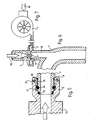
- FIG. 1 is a side elevation view partially in section of a capsule washing drum machine and illustrates the disclosed preferred embodiment of the apparatus assembled in accordance with the present invention for washing and drying garments.
- Figure 2 discloses a top longitudinal elevation view partially in section of a capsule washing drum showing axial drive shaft side Item 1, loading side Item 3, supply and suction ports Item 3, washing inlet Item 4, wall of capsule Item 5, fine sieve type perforations Item 6, in the central filter sleeve Item 7, inside capsule washing drum item 8.
- Figure 3 discloses radial cross-section of the capsule washing drum through section A-A inside Item 7, wall of capsule Item 6, central filter sleeve Item 5, axial drive shafts Item 2 and 3, washing inlet Item 1, supply and vacuum inlet Item 4.
- Figure 4 discloses a from elevation cross-section of a capsule washing drum machine showing cabinet frame Item 1, control panels Item 2 and 3, water supply inlet.
- Figure 5 discloses a rotary swivel joint showing suction port Item 17, stationary 90° inlet/outlet tube bend Item 7, rotary swivel fitted to the axial drive shaft on the capsule washing drum Item 10.
- male rotary body Item 9 female pin retainer Item 8, metal to metal outer seal Item 12, front seal Item 13 rear seal Item 16, central seal and retainer Item 11 and 14, bearing item 15.
- Figure 6 discloses a schematic front elevation partially in section of a venturi jet high vacuum pump with a centrifugal air pump controller, to control suction strength, showing high pressure water inlet Item 19, venturi inlet Item 4, venturi aperture Item 3, centrifugal air pump Item 1, air inlet Item 18, air chamber Item 2, peripheral air ducts Item 5, branch venturi inlet Item 6, to centre line of the 90° radius J/D tube bend Item 7.
- Figure 7 shows a schematic of a centrifugal pump Item 1, air inlet Item 18.
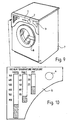
- Figure 8 discloses a side elevation view partially in section of a top loading capsule washing drum machine showing outer cabinet shell Item 9, adjustable levelling feet Item 10, capsule washing drum item 1, press twist lock pressure cap Item 33, top loading door Item 2, rotary transparent glass door Item 2, bearing block retaining axial drive shafts item 3, and 24, support frame for capsule drive shafts Item 4, and 17, water and detergent supply tube to heater tank item 5, water heater Item 16, controls Item 6, detergent drawer Item 7, water supply to drawer Item 8, suction inlet to pump from heater tank Item 11, electric motor Item 12, drives water-detergent pump Item 13, water-detergent supply tube Item 15, 26, and 20, to control valve and drain outlet Item 25, for supply to the capsule washing drum through the solenoid valve rotary swivel joint Item 23, vacuum tube Item 27, venturi tube Item 28, air supply tube Item 29, centrifugal air motor/pump Item 30, air inlet to pump Item 31, electric drive motor and reduction gearing Item 14, motor drive pulley Item 21, capsule washing drum drive pulley
- Figure 9 discloses a diagrammatic view of a pressure/vacuum capsule washing drum machine showing washing machine cabinet shell Item 7, dual loading door Item 6, and the controls Item 1, and2, detergent loading drawer Item 3. -
- Figure 10 shows a diagrammatic view of a front panel display, (sample only) showing an LCD or glow bar indicators Item 5, control dial Item 4.
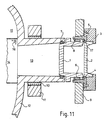
- Figure 11 discloses cross-section elevation view of a dual transparent inner rotary plug door and stationary transparent outer door showing capsule wall Item 12, inside capsule Item 15, fine perforations Item 16, central filter screen sleeve Item 14 bearing item 10, bearing block Item 11, laundry loading port Item 13, pressure seals Item 7, outer cabinet shell Item 9, hinged door Item 3, hinge not shown transparent outer door Item 2, transparent inner door Item 1, bearing Item 6, retaining circlip Item 8, central dual door retaining unit Item 4, retaining countersunk screws Item 5, thrust pressure spring and backing rings Item 17.
- Figure 12 discloses an axial cross-section of a circular sinuous or zig-zag type shape compression spring Item 1, with crests Item 3, and troughs Item 2. For applying continual pressure to the pressure seal around the laundry loading aperture with the dual inner door.
- Figure 11 Item 17.
- Figure 12A shows a radial cross-section of Figure 12 that fits between the two thrust rings for retaining pressure on the inner door seal, Figure 11, Item 7.
- Figure 13 shows a bearing retaining circlip Item 1, compression holes Item 2, for Figure 11, Item 8.
- Figure 14 shows bearing shells inner Item 1, and outer Item 2, with anti-rotation lugs Item 3, and 4, for Figure 11, Item 6.
- Figure 15 shows an axial section of a backing ring Item 1, with two anti-rotational kinks Item 2.
- Figure 15A shows an axial section of the opposite side backing ring Item 1 with anti-rotational kinks Item 2.
- Figure 16 shows an axial section of a friction thrust ring Item 1.
- Figure 17 shows a top longitudinal elevation view partially in section of a capsule washing drum showing axial drive shaft side vacuum conduit Item 1, liquid inlet and outlet Item 2, vacuum inner conduit Item 3, wall of capsule Item 7, laundry inlet Item 5, capsule inner Item 6, sieve type filter screen Item 8, filter apertures Item 4.
- Figure 18 shows a radial cross-section of a capsule washing drum through section A-A inside Item 6, wall of capsule Item 7, sieve type filter screen item 8, fine filter apertures Item 4, vacuum conduit Item 3, vacuum duct Item 1, liquid inlet and outlet Item 2, laundry loading aperture Item 5.
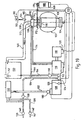
- Figure 19 is a schematic diagram of a pressure washing and vacuum drying machine.
- a pressurised capsule 102 operating at between 15 to 20psc is filled with a charge of articles to be washed, rinsed and dried through a circular opening (not shown) closed by a door 104 in front of a rotary bearing assembly 106, which supports the capsule at one end of its axis of rotation.
- a similar bearing assembly 108 supports the capsule at the other end of its axis of rotation and a rotary sealing joint 110 communicates between the interior of the capsule via the bearing assembly and a solenoid valve assembly 112.
- the latter includes three valves for controlling the admission of a water and detergent mixture into the capsule, the extraction of fluid from the capsule and the delivery of fresh rinsing water to the capsule.
- one of the valves communicates with a pipe 114 leading from the outlet of a pump 116 (driven by a motor 118 having a motor control means 120), to which heated water and detergent are supplied via pipes 122, and solenoid valve 124 from a heating tank 126 containing an immersion heater 128 and supplied via solenoid valve 130 from pipe 132 from a detergent reservoir 132.
- Cold water is conveyed to the heating tank 126 via the solenoid valve 124 from pipe 134, itself connected to a cold water main 136 via solenoid valves 138 and 140.
- Pipe 139 is connected to a hot water main 141 via valve 142.
- Cold water can be conveyed to the detergent reservoir 132 by opening 140 and closing 138, to flush detergent via pipes 132 and valve 130 into the heating tank 126.
- hot water from 141 may be conveyed into and through the reservoir 132 by opening valve 142 and closing valves 138 and 140.
- the pump 116 can supply cold water at 1206.6 kPa (175psi) via pipes 144 to the 90 degree bend via bent pipe 146, from where it is exhausted via drain 148 to a sump 150.
- the latter includes an overflow 152 and a return pipe 154 which when valve 156 is open, provides a return for the water to the pump 116 from the venturi pump (not shown) formed in the 90 degree bend 158.
- pump 116 will produce a higher pressure.
- Air is admitted via an air inlet 160 and centrifugal air pump 162 and mixing device 164.
- the speed of the air pump 162 is controlled by the PLC to control the suction generated by the venturi effect in the venturi pump 158.
- the sump 156 is located in the base of a washing machine embodying the invention to assist in stabilising the machine when in use.
- the capsule is rotated to tumble the articles by an electric motor 16 having a motor control 168, and drive is transmitted from the motor to the capsule via two pulleys 170, 172 and an endless drive belt 174.
- Water/detergent solution is pumped into the capsule at 1206.6 kPa (175psi) through a plurality of 1-2mm holes in a fine mesh filter plate 176. As shown in Figure 19, the plate is at one end of the capsule perpendicular to the axis around which the capsule rotates.
- the rinse cycle may also be performed under positive pressure (ie above ambient) and the rinsing effect is seemingly enhanced by the partial vacuum created at the end of the rinse, by the action of the venturi pump 158.
- Drying of the washed and rinsed articles is effected very efficiently by continuing to run the venturi pump 158 after all water has been sucked from the capsule, and the partial vacuum created in the capsule assists in evaporation of residual moisture for the articles.
- the operation of the various solenoid valves, the time during which they are opened or closed and the intervals between operation thereof, are controlled by the PLC 100, which being programmable permits different washing and rinsing cycles to be performed, in the same way the PLC 100 controls the operation of the various electric motors such as 118, 162 and 166.
Abstract
Description
The user is then able to see which of the programmes has been reached and to control conditions as required in addition to operating the conventional washing machine controls.
Claims (8)
- A machine for washing articles which comprises a sealable enclosure (102) for containing articles to which a mixture of detergent and water (washing liquid) is to be supplied, a heater tank (5; 126) and heater (16; 128) wherein the washing liquid is heated to a high temperature, a water -detergent pump (13; 116) by which the liquid is forced into the enclosure under high pressure, and wherein the washing liquid is replaced with rinsing water and during rinsing the pressure in the enclosure is also maintained above ambient, and the washing liquid and the rinsing water are removed from the articles and from the interior of the enclosure by suction, characterised by a fine-mesh filter (176) through which the washing liquid is forced to enter the enclosure under a pressure of its order of 175 psi (1.2 MPa), thereby to produce finely dispersed or diffused droplets forming a mist or vapour, whereby under the greater than atmospheric pressure in the enclosure, the washing liquid droplets are forced into at least the surface if not through and into the very structure of the material from which the articles are formed, so as to assist the cleaning process.
- A machine as claimed in claim 1 wherein the sealable enclosure is in the form of an elliptical capsule mounted for rotation about an axis through the mid point of its longer axis perpendicular to the latter and comprising a diameter of the cylindrical mid-region.
- A machine as claimed in claim 1 or 2, wherein after rinsing, drying of the articles is assisted by reducing the pressure in the enclosure below ambient, and suction to reduce the enclosure pressure is obtained by a venturi pump [27, 28 (Fig 1); 3, 6 (Fig 6); 158 (Fig 19)] and water is supplied thereto under pressure by a pump (116), and after leaving the venturi pump, the water is conveyed to a sump (150) which includes a return pipe (154) for returning the water to the pump (116).
- A method of washing articles comprising the steps of:inserting an article or articles to be washed into a sealable capsule,sealing the capsule,mixing water with detergent,heating the mixture to a temperature around boiling point,pumping the mixture together with steam into the sealed capsule through a fine mesh filter [to a pressure, of the order of 175 psi (1.2MPa)], so as to form finely dispersed droplets or a mist or vapour, while maintaining the mixture and the capsule interior at a pressure greater than ambientrotating the capsule to agitate the article(s) and effect a mixing of the liquid and steam therewithpumping the liquid from the capsule after a predetermined time,introducing clean water into the capsule, increasing the pressure in the capsule to above ambient and further rotating same to rinse the articlespumping the rinsing water from the capsule after a predetermined timecontinuing to pump the capsule so as to lower the pressure therein to below atmospheric for a further predetermined period of time to assist in evaporative drying of the article(s) therein, andremoving the article(s) after establishing ambient pressure in the capsule.
- A method as claimed in claim 4 wherein removal of washing liquid from the capsule is effected by means of a venturi pump [27, 28 (Fig 1); 3, 6 (Fig 6); 158 (Fig 19)].
- method as claimed in claim 5 wherein removal of rinsing water from the capsule is also effected by means of the venturi pump.
- A method as claimed in claim 5 or 6 wherein removal of air from the capsule to lower the pressure therein is also effected by means of the venturi pump
- A method as claimed in any of claims 5 to 7 wherein water is supplied under pressure from a pump (116) to the venturi pump and after leaving the venturi pump the water is conveyed to a sump (150), from which water is drawn by the pump (116) through a return pipe (154).
Applications Claiming Priority (7)
| Application Number | Priority Date | Filing Date | Title |
|---|---|---|---|
| GB9906800 | 1999-03-25 | ||
| GBGB9906800.9A GB9906800D0 (en) | 1999-03-25 | 1999-03-25 | Pressure washing and vacuum drying machine for garments |
| GBGB9907304.1A GB9907304D0 (en) | 1999-03-25 | 1999-03-31 | Pressure washing and vacuum drying machine for garments |
| GB9907304 | 1999-03-31 | ||
| GB9909836 | 1999-04-29 | ||
| GBGB9909836.0A GB9909836D0 (en) | 1999-03-25 | 1999-04-29 | Pressure washing and vacuum drying maching for garments |
| PCT/GB2000/001082 WO2000058544A1 (en) | 1999-03-25 | 2000-03-23 | Washing and drying machines and dry-cleaning machines |
Publications (2)
| Publication Number | Publication Date |
|---|---|
| EP1163387A1 EP1163387A1 (en) | 2001-12-19 |
| EP1163387B1 true EP1163387B1 (en) | 2005-08-24 |
Family
ID=27269681
Family Applications (1)
| Application Number | Title | Priority Date | Filing Date |
|---|---|---|---|
| EP00911132A Expired - Lifetime EP1163387B1 (en) | 1999-03-25 | 2000-03-23 | Washing and drying machines and dry-cleaning machines |
Country Status (10)
| Country | Link |
|---|---|
| US (2) | US6849094B1 (en) |
| EP (1) | EP1163387B1 (en) |
| JP (1) | JP2002540823A (en) |
| CN (1) | CN1322195C (en) |
| AT (1) | ATE302869T1 (en) |
| AU (1) | AU765575B2 (en) |
| DE (1) | DE60022173T2 (en) |
| ES (1) | ES2246833T3 (en) |
| HK (1) | HK1044177A1 (en) |
| WO (1) | WO2000058544A1 (en) |
Cited By (16)
| Publication number | Priority date | Publication date | Assignee | Title |
|---|---|---|---|---|
| US7665332B2 (en) | 2006-08-15 | 2010-02-23 | Whirlpool Corporation | Steam fabric treatment appliance with exhaust |
| US7681418B2 (en) | 2006-08-15 | 2010-03-23 | Whirlpool Corporation | Water supply control for a steam generator of a fabric treatment appliance using a temperature sensor |
| US7690062B2 (en) | 2007-08-31 | 2010-04-06 | Whirlpool Corporation | Method for cleaning a steam generator |
| US7707859B2 (en) | 2006-08-15 | 2010-05-04 | Whirlpool Corporation | Water supply control for a steam generator of a fabric treatment appliance |
| US7730568B2 (en) | 2006-06-09 | 2010-06-08 | Whirlpool Corporation | Removal of scale and sludge in a steam generator of a fabric treatment appliance |
| US7765628B2 (en) | 2006-06-09 | 2010-08-03 | Whirlpool Corporation | Steam washing machine operation method having a dual speed spin pre-wash |
| US7841219B2 (en) | 2006-08-15 | 2010-11-30 | Whirlpool Corporation | Fabric treating appliance utilizing steam |
| US7861343B2 (en) | 2007-08-31 | 2011-01-04 | Whirlpool Corporation | Method for operating a steam generator in a fabric treatment appliance |
| US7905119B2 (en) | 2007-08-31 | 2011-03-15 | Whirlpool Corporation | Fabric treatment appliance with steam generator having a variable thermal output |
| US7918109B2 (en) | 2007-08-31 | 2011-04-05 | Whirlpool Corporation | Fabric Treatment appliance with steam generator having a variable thermal output |
| US7941885B2 (en) | 2006-06-09 | 2011-05-17 | Whirlpool Corporation | Steam washing machine operation method having dry spin pre-wash |
| US7966683B2 (en) | 2007-08-31 | 2011-06-28 | Whirlpool Corporation | Method for operating a steam generator in a fabric treatment appliance |
| US8037565B2 (en) | 2007-08-31 | 2011-10-18 | Whirlpool Corporation | Method for detecting abnormality in a fabric treatment appliance having a steam generator |
| US8393183B2 (en) | 2007-05-07 | 2013-03-12 | Whirlpool Corporation | Fabric treatment appliance control panel and associated steam operations |
| US8555675B2 (en) | 2007-08-31 | 2013-10-15 | Whirlpool Corporation | Fabric treatment appliance with steam backflow device |
| US8555676B2 (en) | 2007-08-31 | 2013-10-15 | Whirlpool Corporation | Fabric treatment appliance with steam backflow device |
Families Citing this family (33)
| Publication number | Priority date | Publication date | Assignee | Title |
|---|---|---|---|---|
| US8844160B2 (en) | 1997-04-29 | 2014-09-30 | Whirlpool Corporation | Modular fabric revitalizing system |
| US20070266740A9 (en) | 2000-07-25 | 2007-11-22 | Kendall James W | Vertical laundry module |
| KR100484795B1 (en) * | 2002-01-09 | 2005-04-22 | 엘지전자 주식회사 | The Door of A Drum Washer |
| KR100540749B1 (en) | 2003-08-13 | 2006-01-10 | 엘지전자 주식회사 | Steam generator for drum-type washing machine |
| DE10339504A1 (en) * | 2003-08-27 | 2005-04-07 | BSH Bosch und Siemens Hausgeräte GmbH | Washing machine |
| KR101003359B1 (en) * | 2003-12-23 | 2010-12-28 | 삼성전자주식회사 | Drum type washing machine and washing method thereof |
| KR101022226B1 (en) * | 2004-01-06 | 2011-03-17 | 삼성전자주식회사 | Washing Machine And Control Method Thereof |
| KR101135805B1 (en) | 2004-07-29 | 2012-04-19 | 엘지전자 주식회사 | Apparatus for driving valve of gas type dryer |
| US20060117810A1 (en) | 2004-10-22 | 2006-06-08 | Kendall James W | Modular Laundry system with segmented work surface |
| US11255040B2 (en) | 2004-10-22 | 2022-02-22 | Whirlpool Corporation | Modular laundry system |
| US20070151303A1 (en) | 2005-12-30 | 2007-07-05 | Doyle Colleen M | Modular laundry system with work surface having a functional element |
| US20070151304A1 (en) | 2005-12-30 | 2007-07-05 | Kendall James W | Modular laundry system with work surface having a functional insert |
| US20070151306A1 (en) | 2005-12-30 | 2007-07-05 | Gilboe Kevin J | Modular laundry system with work surface |
| US20070151300A1 (en) | 2005-12-30 | 2007-07-05 | Sunshine Richard A | Modular laundry system with horizontal module spanning two laundry appliances |
| US7913419B2 (en) * | 2005-12-30 | 2011-03-29 | Whirlpool Corporation | Non-tumble clothes dryer |
| US7921578B2 (en) * | 2005-12-30 | 2011-04-12 | Whirlpool Corporation | Nebulizer system for a fabric treatment appliance |
| JP4022239B1 (en) * | 2006-08-10 | 2007-12-12 | シャープ株式会社 | Washing dryer and control method thereof |
| US7886392B2 (en) | 2006-08-15 | 2011-02-15 | Whirlpool Corporation | Method of sanitizing a fabric load with steam in a fabric treatment appliance |
| US7753009B2 (en) | 2006-10-19 | 2010-07-13 | Whirlpool Corporation | Washer with bio prevention cycle |
| US20080155759A1 (en) * | 2006-12-27 | 2008-07-03 | Paul Douglas Mantle | Methods and apparatus for channeling liquid in a clothes treating apparatus |
| KR101396408B1 (en) * | 2007-03-05 | 2014-05-20 | 삼성전자주식회사 | Washing machine and method to control spin-drying thereof |
| US7941936B2 (en) * | 2007-05-24 | 2011-05-17 | Ingenious Designs Llc | Garment drying apparatus |
| MX2011012796A (en) * | 2009-06-01 | 2012-01-27 | Procter & Gamble | Fabric refreshing cabinet device comprising a passive heat management system. |
| US20110025177A1 (en) * | 2009-07-30 | 2011-02-03 | Bsh Home Appliances Corporation | Overmold seal and ramp for a household appliance door |
| CN201896551U (en) * | 2010-12-03 | 2011-07-13 | 柳州五菱汽车有限责任公司 | Profiled circular skeleton door of recreational vehicle |
| US20120304394A1 (en) * | 2011-05-31 | 2012-12-06 | Fariborz Dawudian | Method and Apparatus for Cleaning Delicate Textiles |
| US9091017B2 (en) | 2012-01-17 | 2015-07-28 | Co2Nexus, Inc. | Barrier densified fluid cleaning system |
| ITBO20120418A1 (en) * | 2012-07-31 | 2014-02-01 | F M B Fabbrica Macchine Bologna S P A | MACHINE AND METHOD FOR CLEANING FABRICS OR SIMILARS. |
| CN105019200B (en) * | 2014-04-30 | 2017-02-15 | 海尔集团技术研发中心 | Household dry cleaning machine and control method |
| US20190330779A1 (en) * | 2016-12-30 | 2019-10-31 | Shiqing Li | Washing machine |
| TR201918205A2 (en) | 2019-11-21 | 2021-06-21 | Vestel Beyaz Esya Sanayi Ve Ticaret Anonim Sirketi | A swivel joint for white goods. |
| CN114073476B (en) * | 2020-08-19 | 2023-08-25 | 佛山市顺德区美的洗涤电器制造有限公司 | Control method, washing appliance and computer readable storage medium |
| CN116161682A (en) * | 2023-02-25 | 2023-05-26 | 浙江绿海制盐有限责任公司 | Preparation method and equipment of salt |
Family Cites Families (12)
| Publication number | Priority date | Publication date | Assignee | Title |
|---|---|---|---|---|
| US2335560A (en) * | 1940-11-26 | 1943-11-30 | Morton Brayton | Laundry apparatus |
| BE639097A (en) * | 1963-10-24 | |||
| US4489574A (en) * | 1981-11-10 | 1984-12-25 | The Procter & Gamble Company | Apparatus for highly efficient laundering of textiles |
| US4489455A (en) * | 1982-10-28 | 1984-12-25 | The Procter & Gamble Company | Method for highly efficient laundering of textiles |
| US5232476A (en) * | 1990-09-12 | 1993-08-03 | Baxter International Inc. | Solvent recovery and reclamation system |
| DE4236873A1 (en) * | 1992-10-31 | 1994-05-05 | Harald Faller | Washing laundry in washing machine - involves driving washing solution through laundry with pressure; solution is guided in circulation system |
| US5461742A (en) * | 1994-02-16 | 1995-10-31 | Levi Strauss & Co. | Mist treatment of garments |
| US5459945A (en) | 1994-08-03 | 1995-10-24 | Shulenberger; Arthur | Heat recapturing, vacuum assisted evaporative drier |
| MY115384A (en) * | 1994-12-06 | 2003-05-31 | Sharp Kk | Drum type washing machine and drier |
| BE1009718A6 (en) * | 1995-10-20 | 1997-07-01 | Peeters Tom Walter | Washing machine. |
| US5865852A (en) * | 1997-08-22 | 1999-02-02 | Berndt; Dieter R. | Dry cleaning method and solvent |
| US5858022A (en) * | 1997-08-27 | 1999-01-12 | Micell Technologies, Inc. | Dry cleaning methods and compositions |
-
2000
- 2000-03-23 DE DE60022173T patent/DE60022173T2/en not_active Expired - Fee Related
- 2000-03-23 AT AT00911132T patent/ATE302869T1/en not_active IP Right Cessation
- 2000-03-23 ES ES00911132T patent/ES2246833T3/en not_active Expired - Lifetime
- 2000-03-23 JP JP2000608820A patent/JP2002540823A/en active Pending
- 2000-03-23 AU AU33125/00A patent/AU765575B2/en not_active Ceased
- 2000-03-23 US US09/936,635 patent/US6849094B1/en not_active Expired - Fee Related
- 2000-03-23 EP EP00911132A patent/EP1163387B1/en not_active Expired - Lifetime
- 2000-03-23 CN CNB008055114A patent/CN1322195C/en not_active Expired - Fee Related
- 2000-03-23 WO PCT/GB2000/001082 patent/WO2000058544A1/en active IP Right Grant
-
2002
- 2002-06-19 HK HK02104555A patent/HK1044177A1/en not_active IP Right Cessation
-
2004
- 2004-10-08 US US10/961,010 patent/US7207197B2/en not_active Expired - Fee Related
Cited By (16)
| Publication number | Priority date | Publication date | Assignee | Title |
|---|---|---|---|---|
| US7730568B2 (en) | 2006-06-09 | 2010-06-08 | Whirlpool Corporation | Removal of scale and sludge in a steam generator of a fabric treatment appliance |
| US7765628B2 (en) | 2006-06-09 | 2010-08-03 | Whirlpool Corporation | Steam washing machine operation method having a dual speed spin pre-wash |
| US7941885B2 (en) | 2006-06-09 | 2011-05-17 | Whirlpool Corporation | Steam washing machine operation method having dry spin pre-wash |
| US7665332B2 (en) | 2006-08-15 | 2010-02-23 | Whirlpool Corporation | Steam fabric treatment appliance with exhaust |
| US7681418B2 (en) | 2006-08-15 | 2010-03-23 | Whirlpool Corporation | Water supply control for a steam generator of a fabric treatment appliance using a temperature sensor |
| US7707859B2 (en) | 2006-08-15 | 2010-05-04 | Whirlpool Corporation | Water supply control for a steam generator of a fabric treatment appliance |
| US7841219B2 (en) | 2006-08-15 | 2010-11-30 | Whirlpool Corporation | Fabric treating appliance utilizing steam |
| US8393183B2 (en) | 2007-05-07 | 2013-03-12 | Whirlpool Corporation | Fabric treatment appliance control panel and associated steam operations |
| US7905119B2 (en) | 2007-08-31 | 2011-03-15 | Whirlpool Corporation | Fabric treatment appliance with steam generator having a variable thermal output |
| US7918109B2 (en) | 2007-08-31 | 2011-04-05 | Whirlpool Corporation | Fabric Treatment appliance with steam generator having a variable thermal output |
| US7861343B2 (en) | 2007-08-31 | 2011-01-04 | Whirlpool Corporation | Method for operating a steam generator in a fabric treatment appliance |
| US7966683B2 (en) | 2007-08-31 | 2011-06-28 | Whirlpool Corporation | Method for operating a steam generator in a fabric treatment appliance |
| US8037565B2 (en) | 2007-08-31 | 2011-10-18 | Whirlpool Corporation | Method for detecting abnormality in a fabric treatment appliance having a steam generator |
| US7690062B2 (en) | 2007-08-31 | 2010-04-06 | Whirlpool Corporation | Method for cleaning a steam generator |
| US8555675B2 (en) | 2007-08-31 | 2013-10-15 | Whirlpool Corporation | Fabric treatment appliance with steam backflow device |
| US8555676B2 (en) | 2007-08-31 | 2013-10-15 | Whirlpool Corporation | Fabric treatment appliance with steam backflow device |
Also Published As
| Publication number | Publication date |
|---|---|
| US20050092032A1 (en) | 2005-05-05 |
| ATE302869T1 (en) | 2005-09-15 |
| JP2002540823A (en) | 2002-12-03 |
| AU765575B2 (en) | 2003-09-25 |
| DE60022173D1 (en) | 2005-09-29 |
| HK1044177A1 (en) | 2002-10-11 |
| ES2246833T3 (en) | 2006-03-01 |
| EP1163387A1 (en) | 2001-12-19 |
| AU3312500A (en) | 2000-10-16 |
| CN1345389A (en) | 2002-04-17 |
| CN1322195C (en) | 2007-06-20 |
| WO2000058544A1 (en) | 2000-10-05 |
| US6849094B1 (en) | 2005-02-01 |
| DE60022173T2 (en) | 2006-02-16 |
| US7207197B2 (en) | 2007-04-24 |
Similar Documents
| Publication | Publication Date | Title |
|---|---|---|
| EP1163387B1 (en) | Washing and drying machines and dry-cleaning machines | |
| GB2358641A (en) | Washing and drying machines and dry-cleaning machines | |
| US4941333A (en) | Centrifugally draining single drum washing machine | |
| FI78933C (en) | Washing machine and method for removing dirt from textiles | |
| US9284678B2 (en) | Method for processing laundry, and laundry treatment device suitable for carrying out the method | |
| US3039285A (en) | Imperforate drum combination clothes washer and dryer | |
| US8383035B2 (en) | Removing method of smells | |
| RU2415981C2 (en) | Method to control dryer machine and method to control set of laundry machines | |
| CN101142353B (en) | Washing method | |
| KR20050114106A (en) | Washing machine and deodoring method thereof | |
| US2858688A (en) | Combined clothes washing machine and fluid extractor | |
| US3116243A (en) | Adhesion of fabrics to centrifugal extractors | |
| US2925663A (en) | Combination washer-drier with unitary tub assembly | |
| US3358301A (en) | Laundry machine and method | |
| US3997292A (en) | Laundry machine | |
| US3050975A (en) | Laundry machine with suction means for removing moisture | |
| KR100792064B1 (en) | Method of removing smells | |
| JPH08243292A (en) | Washing and drying machine | |
| US2647388A (en) | Washing machine | |
| US2666315A (en) | Squeezer extractor washing machine | |
| GB2372258A (en) | Washer/drier with vacuum assisted drying | |
| CA1066077A (en) | Continuous fresh water flow clothes washer | |
| CA1052589A (en) | Continuous fresh water flow clothes washer | |
| US3984201A (en) | Laundry machine and method of washing clothes | |
| SU165158A1 (en) | INSTALLATION FOR VACUUM DYE CLOTHING [ |
Legal Events
| Date | Code | Title | Description |
|---|---|---|---|
| PUAI | Public reference made under article 153(3) epc to a published international application that has entered the european phase |
Free format text: ORIGINAL CODE: 0009012 |
|
| 17P | Request for examination filed |
Effective date: 20010912 |
|
| AK | Designated contracting states |
Kind code of ref document: A1 Designated state(s): AT BE CH CY DE DK ES FI FR GB GR IE IT LI LU MC NL PT SE |
|
| 17Q | First examination report despatched |
Effective date: 20030110 |
|
| GRAP | Despatch of communication of intention to grant a patent |
Free format text: ORIGINAL CODE: EPIDOSNIGR1 |
|
| GRAS | Grant fee paid |
Free format text: ORIGINAL CODE: EPIDOSNIGR3 |
|
| GRAA | (expected) grant |
Free format text: ORIGINAL CODE: 0009210 |
|
| AK | Designated contracting states |
Kind code of ref document: B1 Designated state(s): AT BE CH CY DE DK ES FI FR GB GR IE IT LI LU MC NL PT SE |
|
| PG25 | Lapsed in a contracting state [announced via postgrant information from national office to epo] |
Ref country code: NL Free format text: LAPSE BECAUSE OF FAILURE TO SUBMIT A TRANSLATION OF THE DESCRIPTION OR TO PAY THE FEE WITHIN THE PRESCRIBED TIME-LIMIT Effective date: 20050824 Ref country code: LI Free format text: LAPSE BECAUSE OF FAILURE TO SUBMIT A TRANSLATION OF THE DESCRIPTION OR TO PAY THE FEE WITHIN THE PRESCRIBED TIME-LIMIT Effective date: 20050824 Ref country code: CH Free format text: LAPSE BECAUSE OF FAILURE TO SUBMIT A TRANSLATION OF THE DESCRIPTION OR TO PAY THE FEE WITHIN THE PRESCRIBED TIME-LIMIT Effective date: 20050824 Ref country code: FI Free format text: LAPSE BECAUSE OF FAILURE TO SUBMIT A TRANSLATION OF THE DESCRIPTION OR TO PAY THE FEE WITHIN THE PRESCRIBED TIME-LIMIT Effective date: 20050824 Ref country code: AT Free format text: LAPSE BECAUSE OF FAILURE TO SUBMIT A TRANSLATION OF THE DESCRIPTION OR TO PAY THE FEE WITHIN THE PRESCRIBED TIME-LIMIT Effective date: 20050824 Ref country code: BE Free format text: LAPSE BECAUSE OF FAILURE TO SUBMIT A TRANSLATION OF THE DESCRIPTION OR TO PAY THE FEE WITHIN THE PRESCRIBED TIME-LIMIT Effective date: 20050824 |
|
| REG | Reference to a national code |
Ref country code: GB Ref legal event code: FG4D |
|
| REG | Reference to a national code |
Ref country code: CH Ref legal event code: EP |
|
| REG | Reference to a national code |
Ref country code: IE Ref legal event code: FG4D |
|
| RAP2 | Party data changed (patent owner data changed or rights of a patent transferred) |
Owner name: NORTH, JOHN HERBERT |
|
| RIN2 | Information on inventor provided after grant (corrected) |
Inventor name: NORTH, JOHN HERBERT |
|
| REF | Corresponds to: |
Ref document number: 60022173 Country of ref document: DE Date of ref document: 20050929 Kind code of ref document: P |
|
| PG25 | Lapsed in a contracting state [announced via postgrant information from national office to epo] |
Ref country code: DK Free format text: LAPSE BECAUSE OF FAILURE TO SUBMIT A TRANSLATION OF THE DESCRIPTION OR TO PAY THE FEE WITHIN THE PRESCRIBED TIME-LIMIT Effective date: 20051124 Ref country code: SE Free format text: LAPSE BECAUSE OF FAILURE TO SUBMIT A TRANSLATION OF THE DESCRIPTION OR TO PAY THE FEE WITHIN THE PRESCRIBED TIME-LIMIT Effective date: 20051124 Ref country code: GR Free format text: LAPSE BECAUSE OF FAILURE TO SUBMIT A TRANSLATION OF THE DESCRIPTION OR TO PAY THE FEE WITHIN THE PRESCRIBED TIME-LIMIT Effective date: 20051124 |
|
| NLT2 | Nl: modifications (of names), taken from the european patent patent bulletin |
Owner name: NORTH, JOHN HERBERT Effective date: 20050928 |
|
| REG | Reference to a national code |
Ref country code: HK Ref legal event code: GR Ref document number: 1044177 Country of ref document: HK |
|
| PG25 | Lapsed in a contracting state [announced via postgrant information from national office to epo] |
Ref country code: PT Free format text: LAPSE BECAUSE OF FAILURE TO SUBMIT A TRANSLATION OF THE DESCRIPTION OR TO PAY THE FEE WITHIN THE PRESCRIBED TIME-LIMIT Effective date: 20060124 |
|
| NLV1 | Nl: lapsed or annulled due to failure to fulfill the requirements of art. 29p and 29m of the patents act | ||
| REG | Reference to a national code |
Ref country code: CH Ref legal event code: PL |
|
| REG | Reference to a national code |
Ref country code: ES Ref legal event code: FG2A Ref document number: 2246833 Country of ref document: ES Kind code of ref document: T3 |
|
| PG25 | Lapsed in a contracting state [announced via postgrant information from national office to epo] |
Ref country code: IE Free format text: LAPSE BECAUSE OF NON-PAYMENT OF DUE FEES Effective date: 20060323 Ref country code: GB Free format text: LAPSE BECAUSE OF NON-PAYMENT OF DUE FEES Effective date: 20060323 |
|
| PG25 | Lapsed in a contracting state [announced via postgrant information from national office to epo] |
Ref country code: LU Free format text: LAPSE BECAUSE OF NON-PAYMENT OF DUE FEES Effective date: 20060331 Ref country code: MC Free format text: LAPSE BECAUSE OF NON-PAYMENT OF DUE FEES Effective date: 20060331 |
|
| PGFP | Annual fee paid to national office [announced via postgrant information from national office to epo] |
Ref country code: IT Payment date: 20060331 Year of fee payment: 7 |
|
| ET | Fr: translation filed | ||
| PLBE | No opposition filed within time limit |
Free format text: ORIGINAL CODE: 0009261 |
|
| STAA | Information on the status of an ep patent application or granted ep patent |
Free format text: STATUS: NO OPPOSITION FILED WITHIN TIME LIMIT |
|
| 26N | No opposition filed |
Effective date: 20060526 |
|
| GBPC | Gb: european patent ceased through non-payment of renewal fee |
Effective date: 20060323 |
|
| REG | Reference to a national code |
Ref country code: IE Ref legal event code: MM4A |
|
| PGFP | Annual fee paid to national office [announced via postgrant information from national office to epo] |
Ref country code: DE Payment date: 20070326 Year of fee payment: 8 |
|
| PGFP | Annual fee paid to national office [announced via postgrant information from national office to epo] |
Ref country code: ES Payment date: 20070410 Year of fee payment: 8 |
|
| PGFP | Annual fee paid to national office [announced via postgrant information from national office to epo] |
Ref country code: FR Payment date: 20070312 Year of fee payment: 8 |
|
| PG25 | Lapsed in a contracting state [announced via postgrant information from national office to epo] |
Ref country code: CY Free format text: LAPSE BECAUSE OF FAILURE TO SUBMIT A TRANSLATION OF THE DESCRIPTION OR TO PAY THE FEE WITHIN THE PRESCRIBED TIME-LIMIT Effective date: 20050824 |
|
| REG | Reference to a national code |
Ref country code: FR Ref legal event code: ST Effective date: 20081125 |
|
| PG25 | Lapsed in a contracting state [announced via postgrant information from national office to epo] |
Ref country code: DE Free format text: LAPSE BECAUSE OF NON-PAYMENT OF DUE FEES Effective date: 20081001 |
|
| PG25 | Lapsed in a contracting state [announced via postgrant information from national office to epo] |
Ref country code: FR Free format text: LAPSE BECAUSE OF NON-PAYMENT OF DUE FEES Effective date: 20080331 |
|
| REG | Reference to a national code |
Ref country code: ES Ref legal event code: FD2A Effective date: 20080324 |
|
| PG25 | Lapsed in a contracting state [announced via postgrant information from national office to epo] |
Ref country code: ES Free format text: LAPSE BECAUSE OF NON-PAYMENT OF DUE FEES Effective date: 20080324 |
|
| PG25 | Lapsed in a contracting state [announced via postgrant information from national office to epo] |
Ref country code: IT Free format text: LAPSE BECAUSE OF NON-PAYMENT OF DUE FEES Effective date: 20070323 |