EP1164283A2 - A fuel injection valve - Google Patents
A fuel injection valve Download PDFInfo
- Publication number
- EP1164283A2 EP1164283A2 EP01114379A EP01114379A EP1164283A2 EP 1164283 A2 EP1164283 A2 EP 1164283A2 EP 01114379 A EP01114379 A EP 01114379A EP 01114379 A EP01114379 A EP 01114379A EP 1164283 A2 EP1164283 A2 EP 1164283A2
- Authority
- EP
- European Patent Office
- Prior art keywords
- fuel injection
- fuel
- valve
- chamber
- passage
- Prior art date
- Legal status (The legal status is an assumption and is not a legal conclusion. Google has not performed a legal analysis and makes no representation as to the accuracy of the status listed.)
- Granted
Links
Images


Classifications
-
- F—MECHANICAL ENGINEERING; LIGHTING; HEATING; WEAPONS; BLASTING
- F02—COMBUSTION ENGINES; HOT-GAS OR COMBUSTION-PRODUCT ENGINE PLANTS
- F02M—SUPPLYING COMBUSTION ENGINES IN GENERAL WITH COMBUSTIBLE MIXTURES OR CONSTITUENTS THEREOF
- F02M63/00—Other fuel-injection apparatus having pertinent characteristics not provided for in groups F02M39/00 - F02M57/00 or F02M67/00; Details, component parts, or accessories of fuel-injection apparatus, not provided for in, or of interest apart from, the apparatus of groups F02M39/00 - F02M61/00 or F02M67/00; Combination of fuel pump with other devices, e.g. lubricating oil pump
- F02M63/0012—Valves
- F02M63/0014—Valves characterised by the valve actuating means
- F02M63/0015—Valves characterised by the valve actuating means electrical, e.g. using solenoid
- F02M63/0026—Valves characterised by the valve actuating means electrical, e.g. using solenoid using piezoelectric or magnetostrictive actuators
-
- F—MECHANICAL ENGINEERING; LIGHTING; HEATING; WEAPONS; BLASTING
- F02—COMBUSTION ENGINES; HOT-GAS OR COMBUSTION-PRODUCT ENGINE PLANTS
- F02M—SUPPLYING COMBUSTION ENGINES IN GENERAL WITH COMBUSTIBLE MIXTURES OR CONSTITUENTS THEREOF
- F02M45/00—Fuel-injection apparatus characterised by having a cyclic delivery of specific time/pressure or time/quantity relationship
- F02M45/12—Fuel-injection apparatus characterised by having a cyclic delivery of specific time/pressure or time/quantity relationship providing a continuous cyclic delivery with variable pressure
-
- F—MECHANICAL ENGINEERING; LIGHTING; HEATING; WEAPONS; BLASTING
- F02—COMBUSTION ENGINES; HOT-GAS OR COMBUSTION-PRODUCT ENGINE PLANTS
- F02M—SUPPLYING COMBUSTION ENGINES IN GENERAL WITH COMBUSTIBLE MIXTURES OR CONSTITUENTS THEREOF
- F02M47/00—Fuel-injection apparatus operated cyclically with fuel-injection valves actuated by fluid pressure
- F02M47/02—Fuel-injection apparatus operated cyclically with fuel-injection valves actuated by fluid pressure of accumulator-injector type, i.e. having fuel pressure of accumulator tending to open, and fuel pressure in other chamber tending to close, injection valves and having means for periodically releasing that closing pressure
- F02M47/027—Electrically actuated valves draining the chamber to release the closing pressure
Definitions
- the present invention relates to a fuel injection valve. More specifically, the present invention relates to a fuel injection valve used for a common-rail type fuel injection system.
- a common-rail fuel injection system of an internal combustion engine is known in the art.
- high pressure fuel is supplied to a reservoir (a common rail) and distributed to respective fuel injection valves from the reservoir. Since high pressure fuel is always stored in the reservoir in the common-rail fuel injection system, high fuel injection pressure from fuel injection valves can be maintained regardless of the engine speed.
- a conventional shaft driven fuel injection pump a so-called jerk-type fuel injection pump
- the fuel injection pressure becomes lower as the engine speed decreases. Therefore, compared with a fuel injection system employing a jerk-type fuel injection pump, since the fuel injection pressure can be set at a high value, better atomization of fuel can be obtained at a low engine speed using the common-rail fuel injection system.
- the condition of combustion and exhaust gas emission at a low speed operation can be improved in the common-rail fuel injection system.
- a fuel injection valve of this type is disclosed, for example, in Japanese Unexamined Patent publication (Kokai) No. 5-71438.
- the fuel injection valve in the '438 publication is provided with a back pressure chamber (a control chamber) which holds high pressure fuel in order to urge a needle toward a position in which the needle closes a fuel injection hole. Further, a solenoid operated three-way valve which communicates the back pressure chamber with a high pressure fuel passage and a low pressure fuel passage selectively is provided. When the three-way valve is kept at a position where the back pressure chamber is connected to the high pressure fuel oil line, since a high pressure fuel oil is supplied to the back pressure chamber, the needle is kept at the position closing the fuel injection hole and, thereby, the fuel injection valve is closed.
- the fuel injection valve in the '438 publication is further provided with a control valve on the passage connecting the three-way valve to the low pressure fuel line.
- the control valve is capable of taking three positions, i.e., a first position which completely blocks the flow of fuel oil from the back pressure chamber to the low pressure fuel line, a second position which allows a partial flow of fuel oil from the back pressure chamber to the low pressure fuel line and a third position which allows a full flow of fuel oil from the back pressure chamber to the low pressure fuel line.
- the three-way valve is switched to the position where the back pressure chamber is connected to the low pressure fuel line during fuel injection. Further, the control valve is switched to the second position at the beginning of fuel injection and held at the third position thereafter.
- the fuel injection characteristics of the fuel injection valve in the '438 publication is such that the fuel injection rate is small at the beginning of fuel injection and large during the rest of fuel injection period, i.e., fuel injection characteristics the same as those of the jerk-type fuel injection pump can be obtained even if the fuel injection valve of the '438 publication is used in a common-rail fuel injection system.
- the fuel injection valve in the '438 publication also has a significant drawback in that it requires two solenoid operated valves (i.e., the three-way valve and the control valve) in order to obtain the fuel injection characteristics having low fuel injection rate at the beginning of fuel injection and high fuel injection rate during the rest of fuel injection period.
- a pilot fuel injection is performed before a main fuel injection in some cases.
- a pilot fuel injection it is sometimes preferable to change the fuel injection characteristics of the pilot fuel injection from that of the main fuel injection in accordance with the engine operating conditions.
- the fuel injection valve in the '438 publication is capable of providing fuel injection characteristics having a low fuel injection rate at the beginning and a high fuel injection rate during the rest of the fuel injection period, it is not possible to employ different fuel injection characteristics for the pilot fuel injection and main fuel injections.
- the object of the present invention is to provide a fuel injection valve having a compact and simple construction and capable of changing its fuel injection characteristics according to the engine operating conditions when used in a common-rail fuel injection system.
- a fuel injection valve comprising a housing provided with a fuel injection hole at one end thereof, a high pressure fuel passage connected to the fuel injection hole, a valve needle for opening and closing the fuel injection hole, a control chamber formed in the housing at an end of the valve needle opposite to the fuel injection hole, a supply passage connecting the high pressure fuel passage and the control chamber for supplying high pressure fuel to the control chamber so that the pressure in the control chamber urges the valve needle toward a position where the valve needle closes the fuel injection hole, at least two spill passages connected to the control chamber for lowering the pressure in the control chamber by spilling fuel in the control chamber to the outside of the housing so that the valve needle moves towards a position where the valve needle opens the fuel injection hole, a control valve for opening and closing the spill passages, the control valve is capable of taking either of a first position where all of the spill passages are closed, a second position where at least one of the spill passages is opened and at least one of the spill passages is closed and a third position where all of
- the control chamber is connected to the high pressure fuel passage and high pressure fuel is always supplied to the control chamber.
- the pressure in the control chamber urges the valve needle toward the position where it closes the fuel injection hole.
- Fuel injection is initiated by lowering the pressure in the control chamber by spilling fuel in the control chamber through spill passages.
- the fuel injection characteristics are adjusted by controlling the rate of pressure drop by adjusting the flow rate through the spill passages.
- a control valve capable of taking three positions is provided.
- the control valve takes a third position, since all of the spill passages are opened, a relatively large amount of fuel flows out from the control chamber through all of the spill passages. Therefore, the pressure in the control chamber decreases rapidly at the second position of the control valve. This causes the valve needle to move toward the position where it opens the fuel injection hole, and thereby fuel injection is carried out with a relatively large increase in the fuel injection rate when the control valve takes the third position.
- the fuel injection characteristics can be changed by switching the position of the control valve between the second and the third position during the fuel injection.
- a fuel injection valve comprising a housing provided with a fuel injection hole at one end thereof, a high pressure fuel passage connected to the fuel injection hole, a valve needle for opening and closing the fuel injection hole, a control chamber formed in the housing at an end of the valve needle opposite to the fuel injection hole, a leak chamber connected to the control chamber through at least two return passages, a leak passage connecting the leak chamber to a low pressure portion outside of the housing and a supply passage connecting the high pressure fuel passage and the leak chamber for supplying high pressure fuel to the leak chamber and a control valve disposed in the leak chamber and provided with a valve element for closing and opening the leak passage, the control valve is capable of taking either of a first position where the valve element closes the leak passage while opening all of the return passages, a second position where the valve element opens the leak passage while closing at least one of the return passages and opening at least one of the return passages and a third position where the valve element opens the leak passage and all of the return passages, when the control valve takes
- the control valve is not directly connected to the high pressure fuel passage, i.e., the high pressure fuel passage is connected to the leak chamber. Therefore, when the control valve takes the second or third positions, high pressure fuel from the high pressure fuel passage is spilled from the leak passage without flowing into the control chamber. Thus, the pressure in the control chamber decreases even if the pressure in the high pressure fuel passage is very high. Further, when the control valve takes the first position, since the leak passage is closed, fuel from the high pressure fuel passage flows into the control chamber through all of the return passage. Therefore, the pressure in the control chamber increases rapidly and the valve needle closes the fuel injection hole in a short time.
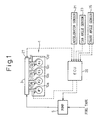
- Fig. 1 schematically shows a fuel injection system of an automobile diesel engine which utilizes a fuel injection valve according to an embodiment of the present invention.
- reference numeral 1 designates an internal combustion engine (in Fig. 1, a four-cylinder diesel engine having No. 1 to No. 4 cylinders is used), and 10a to 10d designate fuel injection valves for injecting fuel directly into the respective No. 1 to No. 4 cylinders.
- the fuel injection valves 10a to 10d are connected to a reservoir (a common-rail) 3 by respective high pressure fuel pipes 11a to 11d.
- the common-rail 3 stores pressurized fuel supplied from a high pressure fuel pump 5 and distributes high pressure fuel to the respective fuel injection valves 10a to 10d through the high pressure fuel pipes 11a to 11d.
- the high pressure fuel pump 5 in this embodiment is, for example, a plunger-type pump with a capacity control mechanism and pressurizes fuel supplied from a fuel tank (not shown) to a predetermined pressure.
- the amount of fuel supplied to the common-rail 3 is feedback-controlled by an electronic control unit (ECU) 20 so that a predetermined target pressure of fuel in the common-rail 3 is always maintained. Therefore, the fuel pressure in the common-rail 3 (i.e., the fuel injection pressure of the fuel injection valves 10a to 10d) can be set at a high value even when the engine speed is low.
- ECU electronice control unit
- the fuel pressure in the common-rail 3 does not change much because the volume of the common-rail 3 is much larger than the volume of fuel injected by one fuel injection.
- the fuel pressure in the common-rail 3 i.e., fuel injection pressure
- the fuel pressure in the common-rail 3 is maintained substantially constant during the fuel injection period of the respective fuel injection valves 10a to 10d.
- reference numeral 20 designates an * electronic control unit (ECU) 20 which controls the engine 1.
- the ECU 20 may be constructed as a micro computer of known type and be provided with a read-only memory (ROM), a random access memory (RAM), a micro processing unit (CPU) connected to each other by a bidirectional bus.
- the ECU 20 in this embodiment performs fuel pressure control in which the common-rail fuel pressure is controlled at a target value determined from the engine operating conditions by adjusting the discharge capacity of the high pressure fuel pump 5.
- the ECU 20 further performs basic control of the engine such as the fuel injection control which controls the fuel injection timing and the fuel injection amount by adjusting opening timing and period of the respective fuel injection valves 10a to 10d.
- a fuel pressure sensor 27 is disposed on the common-rail 3 in order to detect the pressure of fuel in the common-rail 3.
- an accelerator sensor 21 is disposed near the accelerator pedal (not shown) of the engine 1 in order to detect the accelerator opening degree (the amount of accelerator pedal depression by a driver of the vehicle).
- Reference numeral 23 in Fig. 1 is a cam angle sensor for detecting the rotational phase angle of the camshaft of the engine 1 and numeral 25 is a crank angle sensor for detecting the rotational phase angle of the crankshaft of the engine 1.
- the crank angle sensor 23 is disposed near the camshaft and outputs reference pulse signal at every 720 degrees of crankshaft rotation.
- the crank angle sensor 25 is disposed near the crankshaft of the engine 1 and outputs crank angle pulse signal at, for example, every 15 degrees rotation of the crankshaft.
- the ECU 20 calculates the engine speed from the interval of the crank angle pulse signal from the crank angle sensor 25.
- the ECU 20 further calculates the fuel injection timing and the fuel injection amount of the fuel injection valves 10a to 10d based on the calculated engine speed and the accelerator opening degree detected by the accelerator sensor 21. Any known method for calculating the fuel injection timing and the fuel injection amount can be used in this embodiment.
- the fuel injection valves 10a to 10d are identical, the fuel injection valves 10a to 10d are generally designated by reference numeral 10 in the explanation hereinafter.
- Fig. 2 is a longitudinal section view of the fuel injection valve 10 in this embodiment.
- numeral 101 denotes a housing of the fuel injection valve having a substantially cylindrical shape
- 103 denotes an injection hole formed at the bottom of the housing 101
- 105 denotes a valve needle of the fuel injection valve 10.
- Numeral 123 is a high pressure fuel passage formed in the housing 101.
- the high pressure fuel passage 123 is connected to the common-rail 3 through the high pressure fuel pipe (11a to 11d in Fig. 1) at one end thereof and connected to a pressure chamber 107 formed around the valve needle 105 at the portion beneath a needle guide portion 105a thereof.
- the tip of the valve needle 105 is urged to a nozzle seat formed around the injection hole 103 and closes the injection hole 103.
- the pressure in the pressure chamber 107 urges the valve needle 105 upwardly (in the direction opening the injection hole 103, i.e., a valve opening direction).
- the upward force exerted on the valve needle 105 is equal to the fuel pressure in the pressure chamber 107 multiplied by the pressure receiving area (i.e., the area calculated by subtracting the area of the nozzle seat (105c) from the area of the cross section of the needle guide portion 105a).
- a control chamber 109 is formed at the end of the valve needle 105 opposite to the injection hole 103.
- the high pressure fuel passage 123 is connected to the control chamber 109 and the fuel pressure therein exerting on the end (a command piston portion) of the valve needle 105 urges the valve needle in the downward direction (i.e., a valve closing direction).
- a spring 111 for urging the needle 105 in the closing direction is disposed in the control chamber 109.
- the needle 105 is held at the position closing the injection hole 103 by the spring 111 and, thereby, an erroneous fuel injection due to the upward movement of the needle 105 caused by the pressure in a combustion chamber is prevented.
- a leak chamber 130 which is connected to the control chamber 109 by return passages 201 and 203 is disposed as explained later.
- the leak chamber 130 is connected to a low fuel pressure part outside of the fuel injection valve (such as fuel tank) by a leak passage 117.
- Numeral 300 in Fig. 2 is a control valve for blocking the communication between the leak chamber 130 and the leak passage 117.
- the control valve 300 is hydraulically connected to a piezoelectric actuator 303 via a hydraulic chamber 301.
- the piezoelectric actuator 303 is provided with a piston 305 facing the hydraulic chamber 301.
- the piston 305 moves downward and the amount of displacement thereof corresponds to the applied voltage.
- the displacement of the piston 305 is transmitted to the upper end of the control valve 300.
- This causes the control valve to move downward by an amount calculated by multiplying the ratio between the cross sectional areas of the piston 305 and the upper portion of the control valve 300 by the amount of the displacement of the piston 305. Therefore, by applying electric voltage to the piezoelectric actuator 303, the control valve 300 moves downward by the amount corresponding to the applied electric voltage and, thereby, communicates the leak chamber with the leak passage 117.
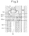
- Fig. 3 is an enlarged section view of the portion of the fuel injection valve 10 around the control chamber 130 and the leak chamber 109 in Fig. 2.
- the control chamber 109 and the leak chamber 130 are connected by return passages 201 and 203 having throttles 201a and 203a, respectively. Further, the control chamber 109 is connected to the high pressure fuel passage 123 by supply passages 207, 209 and a throttle 209a. As shown in Fig. 3, the return passage 203 opens to the leak chamber 130 at the position directly below the control valve 300. Therefore, when the control valve 300 moves to the position where the lower end thereof abuts the floor of the leak chamber 130, i.e., when the control valve 300 takes a full lift position, the return passage 203 is blocked.
- the return passage 209 opens in the leak chamber 130 at the position communicating the leak chamber 130 to the control chamber 109 regardless of the position of the control valve 300.
- the return passage 201, the leak chamber 130 and the leak passage 117 form a spill passage for spilling fuel in the control chamber 109 to the outside of the housing 101 while the return passage 203, the leak chamber 130 and the leak passage 117 form another spill passage for spilling fuel in the control chamber 109 to the outside of the housing 101.
- fuel injection is performed by moving the control valve 300 by applying an electric voltage to the piezoelectric actuator 303.
- the displacement (the lift) of the control valve 300 can be controlled, with extremely high responsiveness, by adjusting electric voltage applied to the piezoelectric actuator 303.
- the control valve 300 is controlled in such a manner that it takes one of the following three positions selectively;
- the speed of the movement of the needle 105 at the full lift position and the medium lift position of the control valve 300 can be set by adjusting the sizes of the throttles 201a and 203a of the return passage 201 and 203 and the throttle 209a of the supply passage 209 in advance.
- the accuracy of fuel injection (i.e., the accuracy of fuel injection timing and amount) becomes low if the time required for actually stopping fuel injection (i.e., the time required for the needle 105 to completely close the injection hole 103), after the control valve 300 returns to the closing position, is long. Therefore, it is preferable to raise the pressure in the control valve 300 as quickly as possible. It is true that the rate of pressure rise in the control chamber 109 can be increased by increasing the flow rate of a fuel flow into the control chamber 109 after the control valve 300 returning to the closing position by increasing the size of the throttle 209a of the supply passage 209. However, if the flow rate of fuel flow into the control chamber 109 is increased, the rate of pressure drop at the beginning of fuel injection also becomes smaller and the needle lift speed at the beginning of fuel injection becomes small.
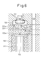
- Fig. 6 shows another embodiment of the fuel injection valve 10 which solves this problem.
- the time required for stopping fuel injection after the control valve 300 returns to its closing position can be shortened while keeping the lifting speed of needle 105, at the beginning of fuel injection, high.
- a second supply passage 211 with a throttle 211a which connects the return passage 203 to the supply passage 207 at the portion upstream of the throttle 209a, is provided in this embodiment.
- a throttle 211a which connects the return passage 203 to the supply passage 207 at the portion upstream of the throttle 209a.
- the greater part of the fuel supplied from the second supply passage 211 leaks to the leak passage 117 from the leak chamber 130 without flowing into the control chamber 109. Therefore, at the medium lift position of the control valve 300 where it is preferable to maintain a large lifting speed of the needle 105, the lifting speed of the needle 105 is substantially the same as that of the embodiment in Fig. 3.
- the lifting speed of the needle 105 can be set at a lower value than that of the embodiment in Fig. 3. Further, since the rate of the pressure rise in the control chamber 109 is increased by fuel flowing into the control chamber 109 from the second supply passage 211 at the closing position of the control valve 300, the time required for completely stopping fuel injection after the control valve 300 returning to the closing position is shortened. Thus, the accuracy of fuel injection is further improved in this embodiment.
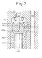
- Fig. 7 shows an example of modifications to the fuel injection valve 10 in Fig. 6.
- the second supply passage 211 is connected to the return passage 203 in Fig. 6, the second supply passage 211 is directly connected to the leak chamber 130 in this embodiment.
- the machining of the second supply passage 211 and the throttle 211a thereof can be largely simplified compared with the embodiment in Fig. 6.
- the fuel injection characteristics of the fuel injection valve can be changed by operating the control valve 300 only, i.e., no control valves other than the control valve 300 is required in the fuel injection valve in the embodiment explained in Figs. 3 to 7. Therefore, the construction of the fuel injection valve can be compact and simple according to these embodiments. Further, since only one control valve is necessary to operate the fuel injection valve, only one electric source is required and the control system for changing fuel injection characteristics of the fuel injection valve can be simplified.
- the position of the control valve 300 can be switched between the closed position, the medium lift position and the full lift position freely by changing the electric voltage applied to the piezoelectric actuator 303 in the fuel injection valves in Figs. 3, 6 and 7. Further, since the response of the piezoelectric actuator 303 is extremely high, the position of the control valve 300 can be switched during a fuel injection period. Therefore, the fuel injection characteristics of the fuel injection valves in Figs. 3, 6 and 7 can be changed during the operation of the engine in accordance with the operating condition as explained hereinafter in Figs. 8 through 12.
- a fuel injection valve is provided with a valve needle which is urged by the pressure of fuel in a control chamber to a closed position where the valve needle closes the fuel injection hole.
- a supply passage with a throttled portion connects a high pressure fuel passage to the control chamber.
- the control chamber is connected to a leak chamber by two return passages.
- the leak chamber has a leak passage for spilling fuel in the leak chamber to the outside of the fuel injection valve.
- a control valve is provided in the leak chamber. The control valve is capable of taking any of a closed position where the leak passage is closed, a medium lift position where the leak passage and two return passages are opened, and a full lift position where the leak passage and only one return passage are opened.
- the pressure in the control chamber is high and the valve needle is kept at the closing position.
- fuel in the control chamber is spilled through the leak passage via return passages and the leak chamber. This causes the valve needle to move to the position where the fuel injection hole is opened.
- the rate of the pressure drop in the control chamber is smaller and the speed of the lift of the valve needle is lower. Therefore, the fuel injection characteristics can be changed by switching the position of the control valve between the medium lift position and the full lift position during fuel injection.
Abstract
Description
- The present invention relates to a fuel injection valve. More specifically, the present invention relates to a fuel injection valve used for a common-rail type fuel injection system.
- A common-rail fuel injection system of an internal combustion engine is known in the art. In a common-rail fuel injection system, high pressure fuel is supplied to a reservoir (a common rail) and distributed to respective fuel injection valves from the reservoir. Since high pressure fuel is always stored in the reservoir in the common-rail fuel injection system, high fuel injection pressure from fuel injection valves can be maintained regardless of the engine speed. When a conventional shaft driven fuel injection pump (a so-called jerk-type fuel injection pump) is used, the fuel injection pressure becomes lower as the engine speed decreases. Therefore, compared with a fuel injection system employing a jerk-type fuel injection pump, since the fuel injection pressure can be set at a high value, better atomization of fuel can be obtained at a low engine speed using the common-rail fuel injection system. Thus, the condition of combustion and exhaust gas emission at a low speed operation can be improved in the common-rail fuel injection system.
- However, there is a drawback in the common-rail fuel injection system. In a jerk-type fuel injection pump, the fuel injection pressure is relatively low at the beginning of fuel injection and increases towards the end of fuel injection. Generally, fuel injected at the beginning of fuel injection largely contributes to the increase in the temperature in the combustion chamber. Therefore, if a large amount of fuel is injected at the beginning of fuel injection, the amount of NOx (nitrogen oxide) formed by the combustion increases due to an increase in the combustion temperature. The fuel injection characteristics of the jerk-type fuel injection pump is preferable from the standpoint of reduction of NOx since the fuel injection rate is low at the beginning of the fuel injection due to low fuel injection pressure at the beginning of fuel injection. Thus, the amount of fuel injected from fuel injection valves at the beginning of the fuel injection is relatively small in the jerk-type fuel injection pump and formation of NOx is suppressed.
- On the other hand, because the fuel injection pressure is substantially constant during fuel injection, the amount of fuel injected at the beginning of fuel injection becomes relatively large. This causes an increase in the amount of NOx formed by combustion.
- In order to overcome this drawback, fuel injection valves having fuel injection characteristics the same as that of the jerk-type fuel injection pump even under a constant fuel injection pressure of common-rail fuel injection system have been proposed.
- A fuel injection valve of this type is disclosed, for example, in Japanese Unexamined Patent publication (Kokai) No. 5-71438.
- The fuel injection valve in the '438 publication is provided with a back pressure chamber (a control chamber) which holds high pressure fuel in order to urge a needle toward a position in which the needle closes a fuel injection hole. Further, a solenoid operated three-way valve which communicates the back pressure chamber with a high pressure fuel passage and a low pressure fuel passage selectively is provided. When the three-way valve is kept at a position where the back pressure chamber is connected to the high pressure fuel oil line, since a high pressure fuel oil is supplied to the back pressure chamber, the needle is kept at the position closing the fuel injection hole and, thereby, the fuel injection valve is closed.
- When the three-way valve is switched to the position where the back pressure chamber is connected to a low pressure fuel line, the pressure in the back pressure chamber is lowered and the needle moves to a position where the fuel injection hole is opened. The fuel injection valve in the '438 publication is further provided with a control valve on the passage connecting the three-way valve to the low pressure fuel line. The control valve is capable of taking three positions, i.e., a first position which completely blocks the flow of fuel oil from the back pressure chamber to the low pressure fuel line, a second position which allows a partial flow of fuel oil from the back pressure chamber to the low pressure fuel line and a third position which allows a full flow of fuel oil from the back pressure chamber to the low pressure fuel line.
- In the '438 publication, the three-way valve is switched to the position where the back pressure chamber is connected to the low pressure fuel line during fuel injection. Further, the control valve is switched to the second position at the beginning of fuel injection and held at the third position thereafter.
- When the control valve is switched to the second position at the beginning of fuel injection, a partial flow of fuel oil from the back pressure chamber to the low pressure fuel line is established and the pressure in the back pressure chamber decreases slightly. This causes the needle to lift a small amount and to slightly open the fuel injection hole at the beginning of fuel injection. When the control valve is switched to the third position, since a full flow of fuel oil from the back pressure chamber to the low pressure fuel line is established, the pressure in the back pressure chamber largely drops. This causes the needle to lift largely and fully open the fuel injection hole. Thus, the amount of fuel injected from the fuel injection hole is small at the beginning of fuel injection and becomes larger during the rest of the fuel injection period. In other words, the fuel injection characteristics of the fuel injection valve in the '438 publication is such that the fuel injection rate is small at the beginning of fuel injection and large during the rest of fuel injection period, i.e., fuel injection characteristics the same as those of the jerk-type fuel injection pump can be obtained even if the fuel injection valve of the '438 publication is used in a common-rail fuel injection system.
- However, the fuel injection valve in the '438 publication also has a significant drawback in that it requires two solenoid operated valves (i.e., the three-way valve and the control valve) in order to obtain the fuel injection characteristics having low fuel injection rate at the beginning of fuel injection and high fuel injection rate during the rest of fuel injection period.
- When the solenoid operated valves are used, the size of the fuel injection valve increases and the construction thereof becomes complicated. Further, since the respective valves operate simultaneously, separate electric sources are required for the respective valves. In addition to that, since the operation timing of two valves must be controlled precisely in order to obtain desired fuel injection characteristics, a complicated control is required for the operation of the valves.
- Further, in diesel engines, a pilot fuel injection is performed before a main fuel injection in some cases. When a pilot fuel injection is performed, it is sometimes preferable to change the fuel injection characteristics of the pilot fuel injection from that of the main fuel injection in accordance with the engine operating conditions. However, though the fuel injection valve in the '438 publication is capable of providing fuel injection characteristics having a low fuel injection rate at the beginning and a high fuel injection rate during the rest of the fuel injection period, it is not possible to employ different fuel injection characteristics for the pilot fuel injection and main fuel injections.
- In view of the problems in the related art as set forth above, the object of the present invention is to provide a fuel injection valve having a compact and simple construction and capable of changing its fuel injection characteristics according to the engine operating conditions when used in a common-rail fuel injection system.
- According to the present invention, there is provided a fuel injection valve comprising a housing provided with a fuel injection hole at one end thereof, a high pressure fuel passage connected to the fuel injection hole, a valve needle for opening and closing the fuel injection hole, a control chamber formed in the housing at an end of the valve needle opposite to the fuel injection hole, a supply passage connecting the high pressure fuel passage and the control chamber for supplying high pressure fuel to the control chamber so that the pressure in the control chamber urges the valve needle toward a position where the valve needle closes the fuel injection hole, at least two spill passages connected to the control chamber for lowering the pressure in the control chamber by spilling fuel in the control chamber to the outside of the housing so that the valve needle moves towards a position where the valve needle opens the fuel injection hole, a control valve for opening and closing the spill passages, the control valve is capable of taking either of a first position where all of the spill passages are closed, a second position where at least one of the spill passages is opened and at least one of the spill passages is closed and a third position where all of the spill passages are opened.
- According to the present invention, the control chamber is connected to the high pressure fuel passage and high pressure fuel is always supplied to the control chamber. The pressure in the control chamber urges the valve needle toward the position where it closes the fuel injection hole. Fuel injection is initiated by lowering the pressure in the control chamber by spilling fuel in the control chamber through spill passages. The fuel injection characteristics are adjusted by controlling the rate of pressure drop by adjusting the flow rate through the spill passages. In this embodiment, in order to adjust the flow rate of fuel flowing through the spill passages, a control valve capable of taking three positions is provided.
- When the control valve takes a first position, all of the spill passages are closed. Since no spillage of fuel from the control chamber occurs in this condition, the pressure in the control chamber is kept at a high value due to fuel supplied from the high pressure fuel passage. Thus, the valve needle is held at the position where the fuel injection hole is closed, thereby fuel injection does not occur.
- When the control valve takes a second position, since at least one of the spill passages is opened and at least one of the spill passages is closed at this position, fuel in the control chamber flows out from the control chamber through only the opened spill passages. Therefore, the pressure in the control chamber decreases at a relatively low rate. This causes the valve needle to move toward the position where the fuel injection is opened at a relatively low speed, and thereby fuel injection is started. However, since the speed of the movement of the valve needle is relatively low, the fuel injection rate increases at a relatively low rate when the control valve takes the second position.
- When the control valve takes a third position, since all of the spill passages are opened, a relatively large amount of fuel flows out from the control chamber through all of the spill passages. Therefore, the pressure in the control chamber decreases rapidly at the second position of the control valve. This causes the valve needle to move toward the position where it opens the fuel injection hole, and thereby fuel injection is carried out with a relatively large increase in the fuel injection rate when the control valve takes the third position. Thus, according to the present invention, the fuel injection characteristics can be changed by switching the position of the control valve between the second and the third position during the fuel injection.
- According to the present invention, there is further provided a fuel injection valve comprising a housing provided with a fuel injection hole at one end thereof, a high pressure fuel passage connected to the fuel injection hole, a valve needle for opening and closing the fuel injection hole, a control chamber formed in the housing at an end of the valve needle opposite to the fuel injection hole, a leak chamber connected to the control chamber through at least two return passages, a leak passage connecting the leak chamber to a low pressure portion outside of the housing and a supply passage connecting the high pressure fuel passage and the leak chamber for supplying high pressure fuel to the leak chamber and a control valve disposed in the leak chamber and provided with a valve element for closing and opening the leak passage, the control valve is capable of taking either of a first position where the valve element closes the leak passage while opening all of the return passages, a second position where the valve element opens the leak passage while closing at least one of the return passages and opening at least one of the return passages and a third position where the valve element opens the leak passage and all of the return passages, when the control valve takes the first position, fuel flowing into the leak chamber from the supply passage flows into the control chamber through all of the return passages and, thereby, the pressure in the control chamber increases and urges the valve needle toward a position where the valve needle closes the fuel injection hole, when the control valve takes either of the second position and the third position, fuel flowing into the leak chamber from the supply passage flows out from the leak chamber through the leak passage and, simultaneously, fuel in the control chamber flows out from the control chamber and is spilled to the outside of the housing via the leak chamber and the leak passage and, thereby, the pressure in the control chamber decreases and allows the movement of the valve needle toward a position where the valve needle opens the fuel injection hole.
- According to the present invention, the control valve is not directly connected to the high pressure fuel passage, i.e., the high pressure fuel passage is connected to the leak chamber. Therefore, when the control valve takes the second or third positions, high pressure fuel from the high pressure fuel passage is spilled from the leak passage without flowing into the control chamber. Thus, the pressure in the control chamber decreases even if the pressure in the high pressure fuel passage is very high. Further, when the control valve takes the first position, since the leak passage is closed, fuel from the high pressure fuel passage flows into the control chamber through all of the return passage. Therefore, the pressure in the control chamber increases rapidly and the valve needle closes the fuel injection hole in a short time.
- The present invention will be better understood from the description as set forth hereinafter, with reference to the accompanying drawings in which:
- Fig. 1 schematically shows the general configuration of an embodiment when the fuel injection valve of the present invention is used in a common-rail fuel injection system for an automobile diesel engine;
- Fig. 2 is a longitudinal section view of a fuel injection valve according to an embodiment of the present invention;
- Fig. 3 is an enlarged section view of a part of the fuel injection valve in Fig. 2 showing the control valve at its closing position;
- Fig. 4 is an enlarged section view showing the control valve at its medium lift position;
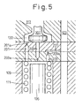
- Fig. 5 is an enlarged section view showing the control valve at its full lift position;
- Fig. 6 is an enlarged section view similar to Fig. 3, showing another embodiment of the present invention;
- Fig. 7 is an enlarged section view showing a modification of the embodiment in Fig. 6;
- Fig. 8 is a timing chart explaining a first embodiment of the fuel injection characteristics obtained by the fuel injection valve according to the present invention;
- Fig. 9 is a timing chart explaining a second embodiment of the fuel injection characteristics obtained by the fuel injection valve according to the present invention;
- Fig. 10 is a timing chart explaining a third embodiment of the fuel injection characteristics obtained by the fuel injection valve according to the present invention;
- Fig. 11 is a timing chart explaining a fourth embodiment of the fuel injection characteristics obtained by the fuel injection valve according to the present Invention;
- Fig. 12 is a timing chart explaining a fifth embodiment of the fuel injection characteristics obtained by the fuel injection valve according to the present invention;
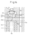
- Fig. 13 is a partial enlarged section view of a fuel injection valve according to an embodiment different from Figs. 2 to 7; and
- Fig. 14 is a partial enlarged section view of a fuel injection valve showing a modification of the embodiment in Fig. 13.
-
- Hereinafter, an embodiment of the present invention will be explained in detail with reference to the accompanying drawings.
- Fig. 1 schematically shows a fuel injection system of an automobile diesel engine which utilizes a fuel injection valve according to an embodiment of the present invention.
- In Fig. 1,
reference numeral 1 designates an internal combustion engine (in Fig. 1, a four-cylinder diesel engine having No. 1 to No. 4 cylinders is used), and 10a to 10d designate fuel injection valves for injecting fuel directly into the respective No. 1 to No. 4 cylinders. Thefuel injection valves 10a to 10d are connected to a reservoir (a common-rail) 3 by respective highpressure fuel pipes 11a to 11d. The common-rail 3 stores pressurized fuel supplied from a highpressure fuel pump 5 and distributes high pressure fuel to the respectivefuel injection valves 10a to 10d through the highpressure fuel pipes 11a to 11d. - The high
pressure fuel pump 5 in this embodiment is, for example, a plunger-type pump with a capacity control mechanism and pressurizes fuel supplied from a fuel tank (not shown) to a predetermined pressure. The amount of fuel supplied to the common-rail 3 is feedback-controlled by an electronic control unit (ECU) 20 so that a predetermined target pressure of fuel in the common-rail 3 is always maintained. Therefore, the fuel pressure in the common-rail 3 (i.e., the fuel injection pressure of thefuel injection valves 10a to 10d) can be set at a high value even when the engine speed is low. Further, though a part of fuel in the common-rail 3 flows out from the common-rail 3 when fuel is injected from thefuel injection valves 10a to 10d, the fuel pressure in the common-rail 3 does not change much because the volume of the common-rail 3 is much larger than the volume of fuel injected by one fuel injection. In other words, the fuel pressure in the common-rail 3 (i.e., fuel injection pressure) is maintained substantially constant during the fuel injection period of the respectivefuel injection valves 10a to 10d. - In Fig. 1,
reference numeral 20 designates an * electronic control unit (ECU) 20 which controls theengine 1. TheECU 20 may be constructed as a micro computer of known type and be provided with a read-only memory (ROM), a random access memory (RAM), a micro processing unit (CPU) connected to each other by a bidirectional bus. TheECU 20 in this embodiment performs fuel pressure control in which the common-rail fuel pressure is controlled at a target value determined from the engine operating conditions by adjusting the discharge capacity of the highpressure fuel pump 5. TheECU 20 further performs basic control of the engine such as the fuel injection control which controls the fuel injection timing and the fuel injection amount by adjusting opening timing and period of the respectivefuel injection valves 10a to 10d. - In this embodiment, a
fuel pressure sensor 27 is disposed on the common-rail 3 in order to detect the pressure of fuel in the common-rail 3. Further, anaccelerator sensor 21 is disposed near the accelerator pedal (not shown) of theengine 1 in order to detect the accelerator opening degree (the amount of accelerator pedal depression by a driver of the vehicle).Reference numeral 23 in Fig. 1 is a cam angle sensor for detecting the rotational phase angle of the camshaft of theengine 1 and numeral 25 is a crank angle sensor for detecting the rotational phase angle of the crankshaft of theengine 1. Thecrank angle sensor 23 is disposed near the camshaft and outputs reference pulse signal at every 720 degrees of crankshaft rotation. Thecrank angle sensor 25 is disposed near the crankshaft of theengine 1 and outputs crank angle pulse signal at, for example, every 15 degrees rotation of the crankshaft. - The
ECU 20 calculates the engine speed from the interval of the crank angle pulse signal from thecrank angle sensor 25. TheECU 20 further calculates the fuel injection timing and the fuel injection amount of thefuel injection valves 10a to 10d based on the calculated engine speed and the accelerator opening degree detected by theaccelerator sensor 21. Any known method for calculating the fuel injection timing and the fuel injection amount can be used in this embodiment. - Next, the construction of the
fuel injection valves 10a to 10d will be explained. Since thefuel injection valves 10a to 10d are identical, thefuel injection valves 10a to 10d are generally designated byreference numeral 10 in the explanation hereinafter. - Fig. 2 is a longitudinal section view of the
fuel injection valve 10 in this embodiment. - In Fig. 2, numeral 101 denotes a housing of the fuel injection valve having a substantially cylindrical shape, 103 denotes an injection hole formed at the bottom of the
housing fuel injection valve 10. -
Numeral 123 is a high pressure fuel passage formed in thehousing 101. The highpressure fuel passage 123 is connected to the common-rail 3 through the high pressure fuel pipe (11a to 11d in Fig. 1) at one end thereof and connected to apressure chamber 107 formed around thevalve needle 105 at the portion beneath a needle guide portion 105a thereof. When thefuel injection valve 10 is closed, the tip of thevalve needle 105 is urged to a nozzle seat formed around theinjection hole 103 and closes theinjection hole 103. In this position, the pressure in thepressure chamber 107 urges thevalve needle 105 upwardly (in the direction opening theinjection hole 103, i.e., a valve opening direction). The upward force exerted on thevalve needle 105 is equal to the fuel pressure in thepressure chamber 107 multiplied by the pressure receiving area (i.e., the area calculated by subtracting the area of the nozzle seat (105c) from the area of the cross section of the needle guide portion 105a). - In the
housing 101, acontrol chamber 109 is formed at the end of thevalve needle 105 opposite to theinjection hole 103. As explained later, the highpressure fuel passage 123 is connected to thecontrol chamber 109 and the fuel pressure therein exerting on the end (a command piston portion) of thevalve needle 105 urges the valve needle in the downward direction (i.e., a valve closing direction). Further, aspring 111 for urging theneedle 105 in the closing direction is disposed in thecontrol chamber 109. When the pressure in thepressure chamber 107 and the pressure in thecontrol chamber 109 are the same, theneedle 105 is urged by thespring 111 in the closing direction. Thus, theneedle 105 is held at the position closing theinjection hole 103 by thespring 111 and, thereby, an erroneous fuel injection due to the upward movement of theneedle 105 caused by the pressure in a combustion chamber is prevented. - In the
housing 101, aleak chamber 130 which is connected to thecontrol chamber 109 byreturn passages leak chamber 130 is connected to a low fuel pressure part outside of the fuel injection valve (such as fuel tank) by aleak passage 117.Numeral 300 in Fig. 2 is a control valve for blocking the communication between theleak chamber 130 and theleak passage 117. - The
control valve 300 is hydraulically connected to apiezoelectric actuator 303 via ahydraulic chamber 301. Thepiezoelectric actuator 303 is provided with apiston 305 facing thehydraulic chamber 301. When an electric voltage is applied to thepiezoelectric actuator 303, thepiston 305 moves downward and the amount of displacement thereof corresponds to the applied voltage. The displacement of thepiston 305 is transmitted to the upper end of thecontrol valve 300. This causes the control valve to move downward by an amount calculated by multiplying the ratio between the cross sectional areas of thepiston 305 and the upper portion of thecontrol valve 300 by the amount of the displacement of thepiston 305. Therefore, by applying electric voltage to thepiezoelectric actuator 303, thecontrol valve 300 moves downward by the amount corresponding to the applied electric voltage and, thereby, communicates the leak chamber with theleak passage 117. - Fig. 3 is an enlarged section view of the portion of the
fuel injection valve 10 around thecontrol chamber 130 and theleak chamber 109 in Fig. 2. - As can be seen from Fig. 3, the
control chamber 109 and theleak chamber 130 are connected byreturn passages throttles control chamber 109 is connected to the highpressure fuel passage 123 bysupply passages throttle 209a. As shown in Fig. 3, thereturn passage 203 opens to theleak chamber 130 at the position directly below thecontrol valve 300. Therefore, when thecontrol valve 300 moves to the position where the lower end thereof abuts the floor of theleak chamber 130, i.e., when thecontrol valve 300 takes a full lift position, thereturn passage 203 is blocked. On the other hand, thereturn passage 209 opens in theleak chamber 130 at the position communicating theleak chamber 130 to thecontrol chamber 109 regardless of the position of thecontrol valve 300. In this embodiment, thereturn passage 201, theleak chamber 130 and theleak passage 117 form a spill passage for spilling fuel in thecontrol chamber 109 to the outside of thehousing 101 while thereturn passage 203, theleak chamber 130 and theleak passage 117 form another spill passage for spilling fuel in thecontrol chamber 109 to the outside of thehousing 101. - In the
fuel injection valve 10 in this embodiment, fuel injection is performed by moving thecontrol valve 300 by applying an electric voltage to thepiezoelectric actuator 303. The displacement (the lift) of thecontrol valve 300 can be controlled, with extremely high responsiveness, by adjusting electric voltage applied to thepiezoelectric actuator 303. In this embodiment, thecontrol valve 300 is controlled in such a manner that it takes one of the following three positions selectively; - a closing position in which the
control valve 300 blocks the communication between theleak chamber 130 and the leak passage 117 (the position in Fig. 3); - a full lift position in which the
control valve 300 abuts the floor of theleak chamber 130 and blocks the communication between theleak chamber 130 and the return passage 203 (the position in Fig. 5); and - a medium lift position in which the
control valve 300 displaces to the position between the closing position and the full lift position where both of theleak passage 117 and thereturn passage 203 are connected to the leak chamber 130 (the position in Fig. 4). -
- The modes of the operation of the fuel injection valve corresponding to these three positions are explained with reference to Figs. 3 to 5.
- (1) Closing position (Fig. 3)
When the
control valve 300 moves to the closing position, theleak chamber 130 is isolated from theleak passage 117. However, since thecontrol chamber 109 is connected to the highpressure fuel passage 123 through thesupply passages control chamber 109 is maintained at a value the same as that of the highpressure fuel passage 123. Therefore, thevalve needle 105 is urged by the pressure in thecontrol chamber 109, together with the force of thespring 111, and blocks theinjection hole 103. Thus, fuel is not injected from thefuel injection valve 10 in this position. - (2) Medium lift position (Fig. 4)
When the
control valve 300 takes the medium lift position, theleak chamber 130 is connected to theleak passage 117. Further, theleak chamber 130 is also connected to thecontrol chamber 109 via thereturn passages control chamber 109 flows into theleak chamber 130 through both of thereturn passages leak chamber 130 through theleak passage 117. Though fuel flows into thecontrol chamber 109 from thesupply passage 209, the pressure in thecontrol chamber 109 drops rapidly in this condition. When the pressure in thecontrol chamber 109 decreases to the point where the sum of the force exerted to theneedle 105 by the pressure in thecontrol chamber 109 and the force of thespring 111 becomes smaller than the force exerted to theneedle 105 by the pressure in thepressure chamber 107, theneedle 105 is moved and opens theinjection hole 103. Thus, high pressure fuel in thepressure chamber 107 is injected from theinjection hole 103 of thefuel injection valve 10. In the medium lift position of thecontrol valve 300, since the speed of the pressure drop in thecontrol chamber 109 is high, the speed of the movement of theneedle 105 for opening theinjection hole 103 also becomes high. Since the fuel injection rate becomes larger as the displacement of theneedle 105 is larger, the rate of increase in the fuel injection rate becomes large when thecontrol valve 300 takes the medium lift position. - (3) Full lift position (Fig. 5)
When the
control valve 300 takes the full lift position, thereturn passage 203 is closed by thecontrol valve 300 and theleak chamber 130 and thecontrol chamber 109 are connected only by thereturn passage 201. Therefore, fuel oil flows out from thecontrol chamber 109 only through thereturn passage 201, thereby the rate of pressure drop in thecontrol chamber 109 becomes relatively small. Thus, theneedle 105 moves at a relatively slow speed and the rate of increase in the fuel injection rate becomes small when thecontrol valve 300 takes its full lift position. -
- When the
control valve 300 returns to its closing position in Fig. 3, from either of medium lift position (Fig. 4) or full lift position (Fig. 5), the leakage of fuel through theleak passage 117 is stopped since theleak passage 117 is closed by thecontrol valve 300 and the rate of pressure drop in thecontrol chamber 109 becomes smaller and the pressure in thecontrol chamber 109 increased by fuel oil flow from thereturn passages control valve 300 returns to its closed position in Fig. 3, theneedle 105 is pressed against theinjection hole 103 and the fuel injection is stopped. - The speed of the movement of the
needle 105 at the full lift position and the medium lift position of thecontrol valve 300 can be set by adjusting the sizes of thethrottles return passage throttle 209a of thesupply passage 209 in advance. - In the embodiment in Fig. 5, the accuracy of fuel injection (i.e., the accuracy of fuel injection timing and amount) becomes low if the time required for actually stopping fuel injection (i.e., the time required for the
needle 105 to completely close the injection hole 103), after thecontrol valve 300 returns to the closing position, is long. Therefore, it is preferable to raise the pressure in thecontrol valve 300 as quickly as possible. It is true that the rate of pressure rise in thecontrol chamber 109 can be increased by increasing the flow rate of a fuel flow into thecontrol chamber 109 after thecontrol valve 300 returning to the closing position by increasing the size of thethrottle 209a of thesupply passage 209. However, if the flow rate of fuel flow into thecontrol chamber 109 is increased, the rate of pressure drop at the beginning of fuel injection also becomes smaller and the needle lift speed at the beginning of fuel injection becomes small. - Fig. 6 shows another embodiment of the
fuel injection valve 10 which solves this problem. In the embodiment in Fig. 6, the time required for stopping fuel injection after thecontrol valve 300 returns to its closing position can be shortened while keeping the lifting speed ofneedle 105, at the beginning of fuel injection, high. - As shown in Fig. 6, a
second supply passage 211, with athrottle 211a which connects thereturn passage 203 to thesupply passage 207 at the portion upstream of thethrottle 209a, is provided in this embodiment. By connecting thesupply passage 207 to thesupply passage 209 through thesecond supply passage 209 and thethrottle 209a, high pressure fuel always flows into thereturn passage 203 from the highpressure fuel passage 123. However, since thethrottle 203a is provided on thereturn passage 203, the greater part of the fuel flowing into thereturn passage 203 from thesecond supply passage 211 flows into theleak chamber 130 without flowing into thecontrol chamber 109 when thereturn passage 203 is not closed (i.e., when thecontrol valve 300 is at the medium lift position). In other words, the greater part of the fuel supplied from thesecond supply passage 211 leaks to theleak passage 117 from theleak chamber 130 without flowing into thecontrol chamber 109. Therefore, at the medium lift position of thecontrol valve 300 where it is preferable to maintain a large lifting speed of theneedle 105, the lifting speed of theneedle 105 is substantially the same as that of the embodiment in Fig. 3. - On the other hand, when the
control valve 300 is at the full lift position of the closing position, high pressure fuel supplied from thesecond supply passage 211 flows into thecontrol chamber 109 through thereturn passage 203 and thethrottle 203a. Therefore, in the full lift position of thecontrol valve 300, where it is preferable to keep the lifting speed of the needle lower, the lifting speed of theneedle 105 can be set at a lower value than that of the embodiment in Fig. 3. Further, since the rate of the pressure rise in thecontrol chamber 109 is increased by fuel flowing into thecontrol chamber 109 from thesecond supply passage 211 at the closing position of thecontrol valve 300, the time required for completely stopping fuel injection after thecontrol valve 300 returning to the closing position is shortened. Thus, the accuracy of fuel injection is further improved in this embodiment. - Fig. 7 shows an example of modifications to the
fuel injection valve 10 in Fig. 6. Though thesecond supply passage 211 is connected to thereturn passage 203 in Fig. 6, thesecond supply passage 211 is directly connected to theleak chamber 130 in this embodiment. By connecting thesecond supply passage 211 directly to theleak chamber 130, the machining of thesecond supply passage 211 and thethrottle 211a thereof can be largely simplified compared with the embodiment in Fig. 6. - As explained above, the fuel injection characteristics of the fuel injection valve can be changed by operating the
control valve 300 only, i.e., no control valves other than thecontrol valve 300 is required in the fuel injection valve in the embodiment explained in Figs. 3 to 7. Therefore, the construction of the fuel injection valve can be compact and simple according to these embodiments. Further, since only one control valve is necessary to operate the fuel injection valve, only one electric source is required and the control system for changing fuel injection characteristics of the fuel injection valve can be simplified. - Next, examples of the lifting speed control of the needle 105 (i.e., the control of the fuel injection characteristics of the fuel injection valve) using fuel injection valves in Figs. 3, 6 and 7 are explained.
- As explained before, the position of the
control valve 300 can be switched between the closed position, the medium lift position and the full lift position freely by changing the electric voltage applied to thepiezoelectric actuator 303 in the fuel injection valves in Figs. 3, 6 and 7. Further, since the response of thepiezoelectric actuator 303 is extremely high, the position of thecontrol valve 300 can be switched during a fuel injection period. Therefore, the fuel injection characteristics of the fuel injection valves in Figs. 3, 6 and 7 can be changed during the operation of the engine in accordance with the operating condition as explained hereinafter in Figs. 8 through 12. - (1) Fig. 8
Fig. 8 is an example of fuel injection
characteristics employed when the interval between the
pilot fuel injection and the main fuel injection is
relatively small. In Fig. 8, the horizontal axis and the
vertical axis represent time and fuel injection rate,
respectively. In this embodiment, when the interval
between the pilot fuel injection and the main fuel
injection is relatively small, (A) the
control valve 300 is held at the medium lift position during the pilot fuel injection in order to obtain a high lifting speed ofneedle 105 and, (B) thecontrol valve 300 is held at the full lift position during the main fuel injection in order to obtain a relatively low lifting speed of the needle 105.By keeping a high lifting speed, the actual fuel injection pressure at theinjection hole 103 of the fuel injection valve (an effective fuel injection pressure) increases rapidly in the pilot fuel injection and a small amount of fuel can be injected at a high speed during the pilot fuel injection. Since fuel injected at a high speed has a large penetration capability, injected fuel burns after it reaches the outer periphery of the combustion chamber even though the amount of fuel injection is small. Therefore, when the main fuel injection is performed, fuel injected by the main fuel injection starts to burn from the portion contacting combustion gas formed by the pilot fuel injection at the outer periphery of the combustion chamber. In other words, combustion of fuel injected by the main fuel injection proceeds from the outer periphery of the combustion chamber toward the center of the combustion chamber. Thus, the combustion temperature of fuel injected by the main fuel injection becomes low and, thereby, formation of NOx is suppressed.Further, since the lifting speed of the needle is relatively small during the main fuel injection, the fuel injection rate at the beginning of the main fuel injection is relatively low in the fuel injection characteristics in Fig. 8. Therefore, in this embodiment, timing of the start of the main fuel injection can be advanced without worsening the combustion. Thus it becomes possible to complete the main fuel injection at a relatively early timing before the temperature in the combustion chamber is lowered near the end of an expansion stroke to, thereby, suppress an increase in the smoke in the exhaust gas caused by fuel injected during the expansion stroke. - (2) Fig. 9
Fig. 9 shows a second embodiment of the fuel
injection characteristics employed by the fuel injection
valves of the above-explained embodiments. In this
embodiment, similarly to Fig. 8, (A) the
control valve 300 is held at the medium lift position during the pilot fuel injection in order to obtain a high lifting speed of theneedle 105 and (B) thecontrol valve 300 is held at the full lift position in order to obtain a relatively low lifting speed of theneedle 105 during the former half of the main fuel injection. However, (c) thecontrol valve 300 is switched from the full lift position to the medium lift position at the middle of the main injection. By holding thecontrol valve 300 at the medium lift position during the latter half of the main fuel injection, the fuel injection rate is increased rapidly during the latter half of the fuel injection in the manner similar to the case where a jerk-type fuel injection pump is used. Therefore, the main fuel injection completes earlier than that in Fig. 8 and the formation of smoke in the exhaust gas is further suppressed. - (3) Fig. 10
Fig. 10 shows a third embodiment of the fuel
injection characteristics employed when the pilot fuel
injection is carried out at timing earlier than Figs. 8
and 9. In this case, since the pilot fuel injection is
carried out in a relatively early period of a compression
stroke of a cylinder, the pressure and temperature in the
combustion chamber is not sufficiently high. Further,
since the position of the piston is relatively low in the
cylinder when the pilot fuel injection is carried out,
fuel injected by the pilot fuel injection is apt to reach
the wall of cylinder without evaporating and to attach to
the wall in a liquid form. When liquid fuel is attached
to the cylinder wall, dilution of the lubricant and
worsening of the lubrication of piston rings due to the
liquid fuel may occur.In order to prevent these problems,
control valve 300 is held at the full lift position when the early pilot fuel injection is carried out. By keeping thecontrol valve 300 at the full lift position during the early pilot fuel injection, since the rate of increase in the effective fuel injection pressure becomes smaller, fuel injected by the pilot fuel injection forms a spray having a low penetration and, thereby, fuel injected by the pilot fuel injection does not reach the cylinder wall in the liquid form. Thus, the problems caused by the liquid fuel attached to the cylinder wall do not occur. - (4) Fig. 11
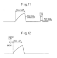
Fig. 11 shows a fourth embodiment of the fuel
injection characteristics of fuel injection valves when a
post fuel injection is carried out. A post fuel
injection is a fuel injection carried out after a main
fuel injection is completed. The post fuel injection is
required when the amount of fuel injection is excessively
large and may cause an increase in the smoke in the
exhaust gas due to incomplete combustion. In this case,
since the post fuel injection is carried out during the
expansion stroke of the cylinder where the position of
the piston is low in the cylinder and the pressure and
temperature in the cylinder is lowered, problems due to
the attachment of liquid fuel to the cylinder wall may
occur. Therefore, similarly to the case in Fig. 10, the
control valve 300 is held at the full lift position during the post fuel injection in this case. By holding thecontrol valve 300 at the full lift position, fuel injected during the post fuel injection forms spray having a low penetration, and the attachment of liquid fuel to the cylinder wall does not occur. - (5) Fig. 12
Fig. 12 shows a fifth embodiment of the fuel
injection characteristics of the fuel injection valves.In this embodiment, (A) the
control valve 300 is first switched to the medium lift position at the beginning of fuel injection and, (B) thecontrol valve 300 is again switched to the full lift position when theneedle 105 starts to lift. In the first and second embodiments of the fuel injection characteristics (Figs. 8 and 9), thecontrol valve 300 is held at the full lift position at the beginning of the fuel injection in order to obtain a relatively low fuel injection rate at the beginning of the fuel injection. However, as explained in Figs. 3 and 5, the rate of decrease in the pressure in thecontrol chamber 109 becomes low when thecontrol valve 300 is at the full lift position since fuel leaks from thecontrol chamber 109 only through the return passage 201 (Fig. 5) in this position. Therefore, a relatively long time is required before the pressure in thecontrol chamber 109 becomes low enough to start the lifting of the needle from the time when a fuel injection command signal is received (i.e., an electric voltage is applied to the piezoelectric actuator 303). This causes a relatively large delay of the actual start of the fuel injection after the fuel injection command signal is received. When the delay time becomes large, since the deviation of the actual fuel injection timing and amount from target values becomes large, the accuracy of fuel injection becomes low.Therefore, in order to reduce the delay of the actual start of the fuel injection, thecontrol valve 300 is first held at the medium lift position in this embodiment. When thecontrol valve 300 is held at the medium lift position, since fuel in thecontrol chamber 109 flows out from both returnpassages control chamber 109 drops rapidly and, thereby, theneedle 105 starts to lift a short time after the fuel injection command is received. Thus, by holding thecontrol valve 300 at the medium lift position at the beginning of the fuel injection, the delay of the actual start of the fuel injection is reduced in this embodiment. Further, thecontrol valve 300 is switched to the full lift position once the needle starts to lift in this embodiment. By switching the position of thecontrol valve 300 to the full lift position, the lift speed of the needle becomes low after it starts to lift. Therefore, the increase in the fuel injection rate after the fuel injection starts becomes low and the fuel injection rate at the beginning of the fuel injection is maintained at a low value.The period between the time when the needle starts to lift and the time when the fuel injection command is received changes in accordance with the pressure in the control chamber 109 (i.e., the common-rail pressure). In this embodiment, the time required for the needle to start to lift is determined by experiment using an actual fuel injection valve. In this experiment, fuel injections are carried out while thecontrol valve 300 is held at the medium lift position and the time required for theneedle 105 to start to move is measured under various common-rail pressures and the relationship between the common-rail pressure and the time required before the actual start of the fuel injection is stored in theECU 20 in the form of a numerical table.In the fuel injection control carried out by theECU 20, the time required before the actual start of the fuel injection is determined from the common-rail pressure using the numerical table explained above. At the beginning of the fuel injection, theECU 20 holds thecontrol valve 300 at the medium lift position for the above-noted time period and, after this time period lapsed, switches the position of thecontrol valve 300 to the full lift position. Thus, the delay of the actual start of the fuel injection is largely reduced in this embodiment.Further, though the time required before the actual start of the fuel injection is determined from the numerical table based on the actual measurement, if the fuel injection valve is equipped with a needle lift sensor which detects the amount of lift of theneedle 105, or a needle lift timing sensor which detects that theneedle 105 has started to lift, the switching of thecontrol valve 300 from the medium lift position to the full lift position can be carried out when the start of the needle lifting is detected by one of the above noted sensors. This further increases the accuracy of the fuel injection.Next, embodiments of the construction of the fuel injection valve according to the present invention, which are different from those in Figs. 3, 6 and 7, will be explained with reference to Figs. 13 and 14.As can be seen from Figs. 13 and 14, the construction of the fuel injection valve in this embodiment is different from that in Fig. 3 in that thesupply passage 209 is connected to theleak chamber 130 instead of thecontrol chamber 109. In the construction in Fig. 3, since thesupply passage 209 is connected to thecontrol chamber 109, fuel flows into thecontrol chamber 109 from thesupply passage 209 even when the fuel in thecontrol chamber 109 flow out therefrom through thereturn passages 201 and 203 (or from thereturn passage 201 only).Therefore, a relatively large amount of fuel flows into thecontrol chamber 109 from thesupply passage 209 especially when the common-rail pressure (i.e., the pressure in the high pressure fuel passage 123) is high. On the other hand, the amount of fuel flows out from thecontrol chamber 109 becomes relatively small, especially when thecontrol valve 300 is at the full lift position. In this case, therefore, the amount of fuel flows into thecontrol chamber 109 through thesupply passage 209 must be reduced to a value less than the amount of fuel flowing out from thecontrol chamber 109 through thereturn passage 201 in order to perform the fuel injection. Thus, thethrottle 209a is disposed on thesupply passage 209 in Fig. 3 in order to reduce the amount fuel flowing into the control chamber 109.However, in the construction in Fig. 3, it is difficult to determine the size ofthrottle 209a in thesupply passage 209. If the size of thethrottle 209a is determined in such a manner that the amount of fuel flowing through thesupply passage 209 is reduced to an appropriate value when the common-rail pressure (i.e., the pressure in the high pressure fuel passage 123) is high, the amount of fuel flowing into thecontrol chamber 109 through thesupply passage 209 becomes excessively small when the common-rail pressure is low. This causes a delay in the timing of stopping fuel injection and lowers the accuracy of fuel injection.The embodiment in Fig. 13 solves this problem by connecting thesupply passage 209 to theleak chamber 130. By connecting thesupply passage 209 to theleak chamber 130, fuel flowing through thesupply passage 209 flows into theleak chamber 130 and is discharged from theleak passage 117 during the fuel injection (i.e., when thecontrol valve 300 is at the medium lift position or full lift position) without flowing into thecontrol chamber 109. Thus, according to the present invention, the start of the fuel injection (i.e., the movement of the needle 105) is not affected by the fuel flowing through thesupply passage 209. Further, when thecontrol valve 300 is in the closed position, fuel flowing into theleak chamber 130 from thesupply passage 209 further flows into thecontrol chamber 109 through bothreturn passages control chamber 109 increases in a short time even if the common-rail pressure is low. Thus, the accuracy of the fuel injection is maintained even when the fuel injection pressure (the common-rail pressure) is low.In this embodiment, if the size (the diameter) of thesupply passage 209 is too small, the end of the fuel injection will be delayed. Further, if the size of thesupply passage 209 is too large, since the amount of fuel discharged through theleak passage 117 increases during the fuel injection, the energy loss in the fuel pump increases. Therefore, it is preferable to determine the size of thesupply passage 209 based on experiment in such a manner that the size of thesupply passage 209 is suitable for all operating conditions of the engine.Fig. 14 shows an example of a modification of the embodiment in Fig. 13. In Fig. 14, although thesupply passage 209 is also connected to theleak chamber 130, a second supply passage 213 connecting the high pressure fuel passage 213 to thecontrol chamber 109 is provided in addition to thesupply passage 209. Further, athrottle 213a is disposed on the second supply passage 213 in order to reduce the amount of fuel flowing into thecontrol chamber 109. In this embodiment, as can be seen from Fig. 14, fuel flows into thecontrol chamber 109 through the second supply passage 213 even when thecontrol valve 300 is at medium lift position or full lift position and fuel flows out from thecontrol chamber 109 through thereturn passages throttle 213a of the second supply passage 213 is set at a relatively small value so that the pressure in thecontrol chamber 109 decreases at a reasonable rate when thecontrol valve 300 is switched to the medium lift position or the full lift position even when the common-rail pressure is high. On the other hand, when thecontrol valve 300 is switched to the closed position, fuel flows into thecontrol chamber 109 through the second supply passage 213 as well as from thesupply passage 209 via thereturn passages control chamber 109 becomes large and the delay in the closing of the fuel injection valve (the delay in the stopping of the fuel injection) can be reduced.As explained above, according to the present invention, the construction of the fuel injection valve is simple and compact and the desired fuel injection characteristics can be easily obtained, in accordance with the operating condition of the engine, when used in a common-rail fuel injection system. -
- A fuel injection valve is provided with a valve needle which is urged by the pressure of fuel in a control chamber to a closed position where the valve needle closes the fuel injection hole. A supply passage with a throttled portion connects a high pressure fuel passage to the control chamber. The control chamber is connected to a leak chamber by two return passages. The leak chamber has a leak passage for spilling fuel in the leak chamber to the outside of the fuel injection valve. A control valve is provided in the leak chamber. The control valve is capable of taking any of a closed position where the leak passage is closed, a medium lift position where the leak passage and two return passages are opened, and a full lift position where the leak passage and only one return passage are opened. In the closing position of the control valve, the pressure in the control chamber is high and the valve needle is kept at the closing position. In the medium lift position and the full lift position, fuel in the control chamber is spilled through the leak passage via return passages and the leak chamber. This causes the valve needle to move to the position where the fuel injection hole is opened. However, at the full lift position, since only one return passage is opened, the rate of the pressure drop in the control chamber is smaller and the speed of the lift of the valve needle is lower. Therefore, the fuel injection characteristics can be changed by switching the position of the control valve between the medium lift position and the full lift position during fuel injection.
Claims (4)
- A fuel injection valve (10) comprising:a housing (101) provided with a fuel injection hole (105) at one end thereof;a high pressure fuel passage (123) connected to the fuel injection hole;a valve needle (105) for opening and closing the fuel injection hole;a control chamber (109) formed in the housing at an end of the valve needle opposite to the fuel injection hole;a supply passage (207, 209) connecting the high pressure fuel passage and the control chamber for supplying high pressure fuel to the control chamber so that the pressure in the control chamber urges the valve needle toward a position where the valve needle closes the fuel injection hole;at least two spill passages (201, 130, 117 and 203, 130, 117) connected to the control chamber for lowering the pressure in the control chamber by spilling fuel in the control chamber to the outside of the housing so that the valve needle moves towards a position where the valve needle opens the fuel injection hole;a control valve (300) for opening and closing the spill passages, the control valve being capable of taking either of a first position where all of the spill passages are closed, a second position where at least one of the spill passages (201, 130, 117) is opened and at least one of the spill passages is closed and a third position where all of the spill passages are opened.
- A fuel injection valve (10) as set forth in claim 1, wherein at least one of the spill passages (201, 130, 117 and 203, 130, 117) is provided with a throttled portion (201a, 203a) at the portion between the control chamber and the control valve for restricting fuel flowing therethrough and the high pressure fuel passage is connected to the at least one of the spill passage at the portion between the throttled portion and the control valve.
- A fuel injection valve (10) comprising:a housing (101) provided with a fuel injection hole (103) at one end thereof;a high pressure fuel passage (123) connected to the fuel injection hole;a valve needle (105) for opening and closing the fuel injection hole;a control chamber (109) formed in the housing at an end of the valve needle opposite to the fuel injection hole;a leak chamber (130) connected to the control chamber through at least two return passages (201, 203);a leak passage (117) connecting the leak chamber to a low pressure portion outside of the housing;a supply passage (209) connecting the high pressure fuel passage and the leak chamber for supplying high pressure fuel to the leak chamber; anda control valve (130) disposed in the leak chamber and provided with a valve element for closing and opening the leak passage;the control valve is capable of taking either of a first position where the valve element closes the leak passage while opening all of the return passages, a second position where the valve element opens the leak passage while closing at least one of the return passages (203) and opening at least one of the return passages (201) and a third position where the valve element opens the leak passage and all of the return passages, wherein;when the control valve takes the first position, fuel flowing into the leak chamber from the supply passage flows into the control chamber through all of the return passages, thereby the pressure in the control chamber increases and urges the valve needle toward a position where the valve needle closes the fuel injection hole, and;when the control valve takes either of the second position and the third position, fuel flowing into the leak chamber from the supply passage flows out from the leak chamber through the leak passage and, simultaneously, fuel in the control chamber flows out from the control chamber and is spilled to the outside of the housing via the leak chamber and the leak passage, thereby the pressure in the control chamber decreases and allows the movement of the valve needle toward a position where the valve needle opens the fuel injection hole.
- A fuel injection valve (10) as set forth in claim 3, further comprises a second supply passage (213) with a throttled portion (213a) directly connecting the high pressure fuel passage (123) to the control chamber (109).
Applications Claiming Priority (2)
| Application Number | Priority Date | Filing Date | Title |
|---|---|---|---|
| JP2000184584A JP3551898B2 (en) | 2000-06-15 | 2000-06-15 | Fuel injection valve |
| JP2000184584 | 2000-06-15 |
Publications (3)
| Publication Number | Publication Date |
|---|---|
| EP1164283A2 true EP1164283A2 (en) | 2001-12-19 |
| EP1164283A3 EP1164283A3 (en) | 2003-11-05 |
| EP1164283B1 EP1164283B1 (en) | 2006-12-13 |
Family
ID=18685003
Family Applications (1)
| Application Number | Title | Priority Date | Filing Date |
|---|---|---|---|
| EP20010114379 Expired - Lifetime EP1164283B1 (en) | 2000-06-15 | 2001-06-13 | A fuel injection valve |
Country Status (4)
| Country | Link |
|---|---|
| EP (1) | EP1164283B1 (en) |
| JP (1) | JP3551898B2 (en) |
| DE (1) | DE60125098T2 (en) |
| ES (1) | ES2277601T3 (en) |
Cited By (15)
| Publication number | Priority date | Publication date | Assignee | Title |
|---|---|---|---|---|
| EP1041272A3 (en) * | 1999-04-01 | 2002-09-18 | Delphi Technologies, Inc. | Fuel injector |
| WO2003004856A1 (en) * | 2001-06-29 | 2003-01-16 | Robert Bosch Gmbh | Fuel injector having injection curve shaping carried out by switchable throttling elements |
| DE10131619A1 (en) * | 2001-06-29 | 2003-01-23 | Bosch Gmbh Robert | Fuel injector with injection course shaping |
| WO2003004860A3 (en) * | 2001-06-29 | 2003-04-17 | Bosch Gmbh Robert | Fuel injector with a switchable control chamber feed |
| WO2004016936A1 (en) * | 2002-07-29 | 2004-02-26 | Robert Bosch Gmbh | Fuel injector with and without pressure amplification with a controllable needle speed and method for the control thereof |
| WO2004048769A1 (en) * | 2002-11-23 | 2004-06-10 | Robert Bosch Gmbh | Fuel injection device with a 3-way control valve for configuring the injection process |
| WO2004051071A1 (en) * | 2002-12-05 | 2004-06-17 | Robert Bosch Gmbh | Fuel injection device comprising a 3/3-way control valve for forming the injection process |
| FR2869651A1 (en) * | 2004-04-30 | 2005-11-04 | Denso Corp | INJECTOR HAVING A STRUCTURE FOR CONTROLLING AN INJECTION NEEDLE |
| FR2894631A1 (en) * | 2005-12-13 | 2007-06-15 | Renault Sas | Fuel injector, especially for diesel engines, comprises a needle valve moving inside a cylinder at a speed which can be varied by an electromagnet and a switch whatever its position in the cylinder |
| WO2007071473A1 (en) * | 2005-12-16 | 2007-06-28 | Robert Bosch Gmbh | Fuel injection valve |
| WO2007098986A1 (en) * | 2006-02-28 | 2007-09-07 | Robert Bosch Gmbh | Fuel injection valve |
| WO2008058799A1 (en) * | 2006-11-16 | 2008-05-22 | Robert Bosch Gmbh | Fuel injector |
| WO2015189082A1 (en) * | 2014-06-12 | 2015-12-17 | Engineering Center Steyr Gmbh & Co Kg | Fluid injection device for an internal combustion engine |
| US10677184B2 (en) | 2013-09-25 | 2020-06-09 | Hitachi Automotive Systems, Ltd. | Drive device for fuel injection device |
| CN116181537A (en) * | 2023-02-08 | 2023-05-30 | 钧风电控科技(泰州)有限责任公司 | Electromagnetic valve sinking offset double-oil-inlet-channel oil sprayer |
Families Citing this family (5)
| Publication number | Priority date | Publication date | Assignee | Title |
|---|---|---|---|---|
| KR20040017596A (en) * | 2002-08-22 | 2004-02-27 | 현대자동차주식회사 | Injector for preventing fuel leaking in diesel engine |
| JP2007205324A (en) * | 2006-02-06 | 2007-08-16 | Denso Corp | Fuel injection valve |
| DE102013112752A1 (en) * | 2013-11-19 | 2015-05-21 | Denso Corporation | fuel injector |
| JP6683143B2 (en) * | 2016-11-14 | 2020-04-15 | 株式会社デンソー | Fuel injector |
| JP6988350B2 (en) * | 2017-10-06 | 2022-01-05 | 株式会社デンソー | Fuel injection device |
Citations (1)
| Publication number | Priority date | Publication date | Assignee | Title |
|---|---|---|---|---|
| JPH0571438A (en) | 1991-09-11 | 1993-03-23 | Nippondenso Co Ltd | Fuel injector |
Family Cites Families (5)
| Publication number | Priority date | Publication date | Assignee | Title |
|---|---|---|---|---|
| EP0807757A1 (en) * | 1994-06-06 | 1997-11-19 | Ganser-Hydromag Ag | Fuel injection valve for internal combustion engines |
| US5687693A (en) * | 1994-07-29 | 1997-11-18 | Caterpillar Inc. | Hydraulically-actuated fuel injector with direct control needle valve |
| DE19640826B4 (en) * | 1995-10-03 | 2004-11-25 | Nippon Soken, Inc., Nishio | Storage fuel injection device and pressure control device therefor |
| DE19742320A1 (en) * | 1997-09-25 | 1999-04-01 | Bosch Gmbh Robert | Fuel injector |
| WO1999061779A1 (en) * | 1998-05-28 | 1999-12-02 | Siemens Aktiengesellschaft | Fuel injection valve for internal combustion engines |
-
2000
- 2000-06-15 JP JP2000184584A patent/JP3551898B2/en not_active Expired - Fee Related
-
2001
- 2001-06-13 EP EP20010114379 patent/EP1164283B1/en not_active Expired - Lifetime
- 2001-06-13 DE DE2001625098 patent/DE60125098T2/en not_active Expired - Fee Related
- 2001-06-13 ES ES01114379T patent/ES2277601T3/en not_active Expired - Lifetime
Patent Citations (1)
| Publication number | Priority date | Publication date | Assignee | Title |
|---|---|---|---|---|
| JPH0571438A (en) | 1991-09-11 | 1993-03-23 | Nippondenso Co Ltd | Fuel injector |
Cited By (19)
| Publication number | Priority date | Publication date | Assignee | Title |
|---|---|---|---|---|
| EP1041272A3 (en) * | 1999-04-01 | 2002-09-18 | Delphi Technologies, Inc. | Fuel injector |
| WO2003004856A1 (en) * | 2001-06-29 | 2003-01-16 | Robert Bosch Gmbh | Fuel injector having injection curve shaping carried out by switchable throttling elements |
| DE10131619A1 (en) * | 2001-06-29 | 2003-01-23 | Bosch Gmbh Robert | Fuel injector with injection course shaping |
| WO2003004860A3 (en) * | 2001-06-29 | 2003-04-17 | Bosch Gmbh Robert | Fuel injector with a switchable control chamber feed |
| WO2004016936A1 (en) * | 2002-07-29 | 2004-02-26 | Robert Bosch Gmbh | Fuel injector with and without pressure amplification with a controllable needle speed and method for the control thereof |
| US7347385B2 (en) | 2002-11-23 | 2008-03-25 | Robert Bosch Gmbh | Fuel injection device with a 3-way control valve for configuring the injection process |
| WO2004048769A1 (en) * | 2002-11-23 | 2004-06-10 | Robert Bosch Gmbh | Fuel injection device with a 3-way control valve for configuring the injection process |
| DE10254749A1 (en) * | 2002-11-23 | 2004-06-17 | Robert Bosch Gmbh | Fuel injection device with a 3/3-way control valve for injection course shaping |
| WO2004051071A1 (en) * | 2002-12-05 | 2004-06-17 | Robert Bosch Gmbh | Fuel injection device comprising a 3/3-way control valve for forming the injection process |
| FR2869651A1 (en) * | 2004-04-30 | 2005-11-04 | Denso Corp | INJECTOR HAVING A STRUCTURE FOR CONTROLLING AN INJECTION NEEDLE |
| US7284712B2 (en) | 2004-04-30 | 2007-10-23 | Denso Corporation | Injector having structure for controlling nozzle needle |
| FR2894631A1 (en) * | 2005-12-13 | 2007-06-15 | Renault Sas | Fuel injector, especially for diesel engines, comprises a needle valve moving inside a cylinder at a speed which can be varied by an electromagnet and a switch whatever its position in the cylinder |
| WO2007071473A1 (en) * | 2005-12-16 | 2007-06-28 | Robert Bosch Gmbh | Fuel injection valve |
| WO2007098986A1 (en) * | 2006-02-28 | 2007-09-07 | Robert Bosch Gmbh | Fuel injection valve |
| WO2008058799A1 (en) * | 2006-11-16 | 2008-05-22 | Robert Bosch Gmbh | Fuel injector |
| US10677184B2 (en) | 2013-09-25 | 2020-06-09 | Hitachi Automotive Systems, Ltd. | Drive device for fuel injection device |
| WO2015189082A1 (en) * | 2014-06-12 | 2015-12-17 | Engineering Center Steyr Gmbh & Co Kg | Fluid injection device for an internal combustion engine |
| CN116181537A (en) * | 2023-02-08 | 2023-05-30 | 钧风电控科技(泰州)有限责任公司 | Electromagnetic valve sinking offset double-oil-inlet-channel oil sprayer |
| CN116181537B (en) * | 2023-02-08 | 2024-01-23 | 钧风电控科技(泰州)有限责任公司 | Electromagnetic valve sinking offset double-oil-inlet-channel oil sprayer |
Also Published As
| Publication number | Publication date |
|---|---|
| DE60125098D1 (en) | 2007-01-25 |
| JP3551898B2 (en) | 2004-08-11 |
| EP1164283B1 (en) | 2006-12-13 |
| EP1164283A3 (en) | 2003-11-05 |
| DE60125098T2 (en) | 2007-06-28 |
| JP2001355533A (en) | 2001-12-26 |
| ES2277601T3 (en) | 2007-07-16 |
Similar Documents
| Publication | Publication Date | Title |
|---|---|---|
| EP1164283B1 (en) | A fuel injection valve | |
| US6253734B1 (en) | Fuel delivery system of an internal combustion engine | |
| US7320311B2 (en) | Pressure boosting common rail fuel injection apparatus and fuel injection control method therefor | |
| US5771865A (en) | Fuel injection system of an engine and a control method therefor | |
| EP0748417B1 (en) | Hydraulically actuated electronic fuel injection system | |
| US6145492A (en) | Control valve for a fuel injection valve | |
| US7431017B2 (en) | Multi-source fuel system having closed loop pressure control | |
| US7275522B2 (en) | Method and apparatus for controlling a valve, and method and apparatus for controlling a pump-nozzle apparatus with the valve | |
| CN101849098A (en) | Ejecting system and the method that is used to make ejecting system | |
| JPH02191865A (en) | Fuel injection device | |
| US5558067A (en) | Double pulsing electronic unit injector solenoid valve to fill timing chamber before metering chamber | |
| US6527199B1 (en) | Fuel injection valve for an internal combustion engine | |
| JP4550991B2 (en) | Fuel / water injection internal combustion engine | |
| JPH031508B2 (en) | ||
| JP4239332B2 (en) | Fuel injection device for internal combustion engine | |
| US20090173316A1 (en) | Injection means for a combustion engine | |
| JPH0454064B2 (en) | ||
| JP3082622B2 (en) | Fuel injection control device and control method thereof | |
| EP1347169B1 (en) | Fuel injection valve | |
| US11168628B2 (en) | Engine control device | |
| JP2002332933A (en) | Fuel injection device | |
| JPH078841Y2 (en) | Fuel injector | |
| US20030164404A1 (en) | Fuel-injection valve for internal combustion engines | |
| JPS618463A (en) | Fuel injection valve for internal-combustion engine | |
| JPH0754563Y2 (en) | Valve drive for internal combustion engine |
Legal Events
| Date | Code | Title | Description |
|---|---|---|---|
| PUAI | Public reference made under article 153(3) epc to a published international application that has entered the european phase |
Free format text: ORIGINAL CODE: 0009012 |
|
| 17P | Request for examination filed |
Effective date: 20010613 |
|
| AK | Designated contracting states |
Kind code of ref document: A2 Designated state(s): AT BE CH CY DE DK ES FI FR GB GR IE IT LI LU MC NL PT SE TR |
|
| AX | Request for extension of the european patent |
Free format text: AL;LT;LV;MK;RO;SI |
|
| PUAL | Search report despatched |
Free format text: ORIGINAL CODE: 0009013 |
|
| AK | Designated contracting states |
Kind code of ref document: A3 Designated state(s): AT BE CH CY DE DK ES FI FR GB GR IE IT LI LU MC NL PT SE TR |
|
| AX | Request for extension of the european patent |
Extension state: AL LT LV MK RO SI |
|
| RIC1 | Information provided on ipc code assigned before grant |
Ipc: 7F 02M 59/46 B Ipc: 7F 02M 47/02 A |
|
| REG | Reference to a national code |
Ref country code: SE Ref legal event code: TRGR |
|
| AKX | Designation fees paid |
Designated state(s): DE ES FR GB IT SE |
|
| GRAP | Despatch of communication of intention to grant a patent |
Free format text: ORIGINAL CODE: EPIDOSNIGR1 |
|
| GRAS | Grant fee paid |
Free format text: ORIGINAL CODE: EPIDOSNIGR3 |
|
| GRAA | (expected) grant |
Free format text: ORIGINAL CODE: 0009210 |
|
| AK | Designated contracting states |
Kind code of ref document: B1 Designated state(s): DE ES FR GB IT SE |
|
| REG | Reference to a national code |
Ref country code: GB Ref legal event code: FG4D |
|
| REF | Corresponds to: |
Ref document number: 60125098 Country of ref document: DE Date of ref document: 20070125 Kind code of ref document: P |
|
| ET | Fr: translation filed | ||
| REG | Reference to a national code |
Ref country code: ES Ref legal event code: FG2A Ref document number: 2277601 Country of ref document: ES Kind code of ref document: T3 |
|
| PLBE | No opposition filed within time limit |
Free format text: ORIGINAL CODE: 0009261 |
|
| STAA | Information on the status of an ep patent application or granted ep patent |
Free format text: STATUS: NO OPPOSITION FILED WITHIN TIME LIMIT |
|
| 26N | No opposition filed |
Effective date: 20070914 |
|
| PGFP | Annual fee paid to national office [announced via postgrant information from national office to epo] |
Ref country code: DE Payment date: 20080619 Year of fee payment: 8 Ref country code: ES Payment date: 20080708 Year of fee payment: 8 Ref country code: SE Payment date: 20080609 Year of fee payment: 8 |
|
| PGFP | Annual fee paid to national office [announced via postgrant information from national office to epo] |
Ref country code: FR Payment date: 20080617 Year of fee payment: 8 Ref country code: IT Payment date: 20080625 Year of fee payment: 8 |
|
| PGFP | Annual fee paid to national office [announced via postgrant information from national office to epo] |
Ref country code: GB Payment date: 20080618 Year of fee payment: 8 |
|
| GBPC | Gb: european patent ceased through non-payment of renewal fee |
Effective date: 20090613 |
|
| REG | Reference to a national code |
Ref country code: FR Ref legal event code: ST Effective date: 20100226 |
|
| PG25 | Lapsed in a contracting state [announced via postgrant information from national office to epo] |
Ref country code: FR Free format text: LAPSE BECAUSE OF NON-PAYMENT OF DUE FEES Effective date: 20090630 |
|
| PG25 | Lapsed in a contracting state [announced via postgrant information from national office to epo] |
Ref country code: GB Free format text: LAPSE BECAUSE OF NON-PAYMENT OF DUE FEES Effective date: 20090613 |
|
| PG25 | Lapsed in a contracting state [announced via postgrant information from national office to epo] |
Ref country code: DE Free format text: LAPSE BECAUSE OF NON-PAYMENT OF DUE FEES Effective date: 20100101 |
|
| REG | Reference to a national code |
Ref country code: ES Ref legal event code: FD2A Effective date: 20090615 |
|
| PG25 | Lapsed in a contracting state [announced via postgrant information from national office to epo] |
Ref country code: ES Free format text: LAPSE BECAUSE OF NON-PAYMENT OF DUE FEES Effective date: 20090615 |
|
| PG25 | Lapsed in a contracting state [announced via postgrant information from national office to epo] |
Ref country code: IT Free format text: LAPSE BECAUSE OF NON-PAYMENT OF DUE FEES Effective date: 20090613 |
|
| PG25 | Lapsed in a contracting state [announced via postgrant information from national office to epo] |
Ref country code: SE Free format text: LAPSE BECAUSE OF NON-PAYMENT OF DUE FEES Effective date: 20090614 |