EP1167086A2 - Method for alarming decrease in tyre air pressure and apparatus used therefor - Google Patents
Method for alarming decrease in tyre air pressure and apparatus used therefor Download PDFInfo
- Publication number
- EP1167086A2 EP1167086A2 EP01305387A EP01305387A EP1167086A2 EP 1167086 A2 EP1167086 A2 EP 1167086A2 EP 01305387 A EP01305387 A EP 01305387A EP 01305387 A EP01305387 A EP 01305387A EP 1167086 A2 EP1167086 A2 EP 1167086A2
- Authority
- EP
- European Patent Office
- Prior art keywords
- tyre
- rotational information
- vehicle
- turning radius
- steering angle
- Prior art date
- Legal status (The legal status is an assumption and is not a legal conclusion. Google has not performed a legal analysis and makes no representation as to the accuracy of the status listed.)
- Granted
Links
Images


Classifications
-
- B—PERFORMING OPERATIONS; TRANSPORTING
- B60—VEHICLES IN GENERAL
- B60C—VEHICLE TYRES; TYRE INFLATION; TYRE CHANGING; CONNECTING VALVES TO INFLATABLE ELASTIC BODIES IN GENERAL; DEVICES OR ARRANGEMENTS RELATED TO TYRES
- B60C23/00—Devices for measuring, signalling, controlling, or distributing tyre pressure or temperature, specially adapted for mounting on vehicles; Arrangement of tyre inflating devices on vehicles, e.g. of pumps or of tanks; Tyre cooling arrangements
- B60C23/06—Signalling devices actuated by deformation of the tyre, e.g. tyre mounted deformation sensors or indirect determination of tyre deformation based on wheel speed, wheel-centre to ground distance or inclination of wheel axle
- B60C23/061—Signalling devices actuated by deformation of the tyre, e.g. tyre mounted deformation sensors or indirect determination of tyre deformation based on wheel speed, wheel-centre to ground distance or inclination of wheel axle by monitoring wheel speed
Definitions
- the present invention relates to a method for alarming decrease in tyre air pressure and an apparatus used therefor. More particularly, it relates to a method for alarming decrease in tyre air pressure and an apparatus used therefor with which it is possible to accurately perform cornering correction and to improve the accuracy of detecting a decompressed condition of a tyre.
- a conventional apparatus for detecting decrease in tyre air pressure determines a decompressed condition of a tyre based on the information of four ABS wheel speed sensors.
- DWS system determines a decompressed condition of a tyre based on the information of four ABS wheel speed sensors.
- a conventional DWS performs cornering correction by obtaining a cornering radius (turning radius) based on a wheel speed ratio of the inner and outer following wheels (which are the rear wheels in the case of a FF vehicle and the front wheels in the case of a FR vehicle) and calculating an amount of change in longitudinal load and an amount of change in slip ratio accompanying the shift of load on the basis of the obtained value.
- the present invention has been made in view of these facts, and it is an object of the present invention to provide a method for alarming decrease in tyre air pressure and an apparatus used therefor which is capable of accurately performing cornering correction and to improve the accuracy of detecting a decompressed condition.
- an apparatus for alarming decrease in tyre air pressure based on rotational information from tyres attached to a four-wheeled vehicle comprising: a rotation information detecting means for detecting rotational information of each tyre; a steering angle detecting means for detecting a steering angle; a memory means for storing the rotational information of each tyre and the steering angle; a turning radius calculating and processing means for calculating a turning radius based on the rotational information of each tyre; a judged value calculating means and processing means for calculating a judged value based on the rotational information of each tyre; and a correction means for correcting the turning radius in case it has been determined by the steering angle detecting means that the vehicle is in a straight-ahead driving condition though the driving condition of the vehicle is a turning condition when being based on the turning radius obtained on the basis of the rotational information.
- an apparatus for alarming decrease in tyre air pressure based on rotational information obtained from tyres attached to a four-wheeled vehicle comprising: a rotational information detecting means for detecting rotational information of each tyre; a steering angle detecting means for detecting steering angle; a memory means for storing the rotational information of each tyre and the steering angle; a turning radius calculating and processing means for calculating a turning radius based on the rotational information of each tyre; a correction means for correcting the turning radius in case it has been determined by the steering angle detecting means that the vehicle is in a straight-ahead driving condition though the driving condition of the vehicle is a turning condition when being based on the turning radius obtained on the basis of the rotational information; and a decompression determining means for determining a decompressed condition of a tyre in case a correction coefficient for the turning radius as obtained by the correction means is not less than a
- a method for alarming decrease in tyre air pressure based on rotational information obtained from tyres attached to a four-wheeled vehicle comprising the steps of; detecting rotational information of each tyre; detecting a steering angle; calculating a reciprocal of a turning radius based on the rotational information of each tyre; calculating a judged value based on the rotational information of each tyre; and correcting, when performing correction of the judged value for decompressed condition due to cornering, the turning radius in case it has been determined on the basis of the steering angle that the vehicle is in a straight-ahead driving condition though the driving condition of the vehicle is a turning condition when being based on the turning radius obtained on the basis of the rotational information.
- a method for alarming decrease in tyre air pressure based on rotational information obtained from tyres attached to a four-wheeled vehicle comprising the steps of: detecting rotational information of each tyre; detecting a steering angle; storing the rotation information of each tyre and the steering angle; calculating a turning radius based on the rotational information of each tyre; correcting the turning radius in case it has been determined on the basis of the steering angle that the vehicle is in a straight-ahead driving condition though the driving condition of the vehicle is a turning condition when being based on the turning radius obtained on the basis of the rotational information; and determining a decompressed condition of a tyre in case a correction coefficient for the turning radius as obtained during the correction process is not less than a threshold.
- an apparatus for alarming decrease in tyre air pressure based on rotational information obtained from tyres attached to a four-wheeled vehicle comprising; a rotation information detecting means for detecting rotational information of each tyre; a memory means for storing the rotational information of each tyre; a calculating and processing means for calculating a judged value based on the rotational information of each tyre; and a judged value correcting means for correcting the judged value based on a lateral acceleration obtained through a lateral acceleration sensor provided in the vehicle.
- an apparatus for alarming decrease in tyre air pressure based on rotational information obtained from tyres attached to a four-wheeled vehicle comprising: a rotational information detecting means for detecting rotational information of each tyre; a memory means for storing the rotational information of each tyre; a calculating and processing means for calculating a judged value based on the rotational information of each tyre; and a judged value correcting means for correcting the judged value based on a lateral acceleration obtained on a basis of values of a yaw rate sensor provided in the vehicle.
- a method for alarming decrease in tyre air pressure based on rotational information obtained from tyres attached to a four-wheeled vehicle comprising the steps of: detecting rotational information of each tyre; storing the rotational information of each tyre; calculating a judged value based on the rotational information of each tyre; and correcting the judged value based on a lateral acceleration obtained through a lateral acceleration sensor provided in the vehicle.
- a method for alarming decrease in tyre air pressure based on rotational information obtained from tyres attached to a four-wheeled vehicle comprising the steps of: detecting rotational information of each tyre; storing the rotational information of each tyre; calculating a judged value based on the rotational information of each tyre; and correcting the judged value based on a lateral acceleration obtained on a basis of values of a yaw rate sensor provided in the vehicle.
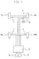
- the rotational information detecting means 1 may be a wheel speed sensor for generating rotational pulse by using an electromagnetic pickup or similar device to obtain wheel speeds (rotational speeds) on the basis of the number of pulses, or an angular velocity sensor including those in which electricity is generated by utilising rotation such as a dynamo to obtain the wheel speed on the basis of the voltage thereof.
- the steering angle detecting means S may be an ordinary steering angle sensor. Outputs of the rotational information detecting means 1 and the steering angle detecting means are supplied to a control unit 2 such as an ABS.
- a display means 3 composed of liquid crystal display elements, plasma display elements, or a CRT for informing a tyre W i of which air pressure has decreased, and an initialisation switch 4 which can be operated by the driver.
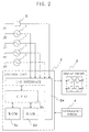
- the control unit 2 comprises, as shown in Figure 2, an I/O interface 2a required for send/receiving signals to/from an external device, a CPU 2b which functions as a centre of calculation, a ROM 2c which stores a control operation program for the CPU 2b, and a RAM 2d into which data are temporally written and are read out therefrom when the CPU 2b performs control operations.
- the turning radius calculating and processing means, judged value calculating and processing means and turning radius correcting means in the present Embodiment 1 are included in the control unit 2.
- Each rotational information detecting means 1 outputs a pulse signal corresponding to the number of revolutions of the tyre W i (hereinafter referred to as "wheel velocity pulse").
- the amount of change in the radius of rotation of the tyres might thus be given as a linear expression of the lateral G.
- slip of the driving wheels will increase in accordance with a decrease in load of the tyres.
- slip of the driving tyres outside of the corner will decrease while the slip inside thereof increases.
- the average slip amount of the right and left tyres owing to cornering being substantially identical and the amount of shift in slip rate being further proportional to the amount of shift in load, the amount of shift in slip rate might be considered to be substantially proportional to the average slip amount.
- variable components of the DEL values owing to lateral G might be given by the following equation (2) based on the linear expression for the lateral G and the linear expression for the average slip rate:
- Variable component of DEL lateral Gx(constant 1+DFRxconstant 2)
- the constant 1 is a primary coefficient of the lateral G affected by the shift in load, it is expressed as a difference in influence of rotation radius between the front and rear by the shift in load since the amount of shift in load is not identical for the front and rear shafts.
- Corrected DEL DEL-lateral Gx(constant 1+DFRxconstant 2)
- DFR denotes a slip rate of the driving wheels that is obtained by (V1+V2)/(V3+V4)-1 in the case of FF (front engine/front drive) and FF based on 4WD vehicles and by (V3+V4)/(V1+V2)-1 in the case of FR (front engine/rear drive) vehicles.
- RT WD denotes a tread width (m) of the rear wheels.
- the constant 1, constant 2 and constant 3 in the above equation (3) and equation (5) are obtained by calculation in the control unit based on the lateral G, DEL and DFR, respectively which are obtained on the basis of wheel speed obtained by the speed sensor of the vehicle while the vehicle is running on a corner with the tyres being at normal internal pressure. Since variations will occur in the constants 1 to 3 depending on the values of the lateral G and the DFR, it is preferable to utilise mean values of the respective variations.
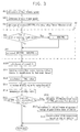
- the present invention is thus arranged that information obtained by the steering angle detecting means is considered and if it is judged on the basis of this information that the vehicle is in a straight-ahead running condition, the value for the RECPR is considered to be an error as long as the value of the RECPR obtained by equation (5) is not 0, and the RECPR is corrected accordingly. That is, a wheel speed for the wheels is first detected by the rotational information detecting means and corrected thereafter as illustrated in Figure 3 (Steps S1 and S2). Then, the RECPR is calculated by using equation (5) and stored (Step S3).
- Information which is obtained from the steering angle detecting means e.g.
- lateral G is calculated by using equation (4) which is an ordinary step (Step S10) and in case one of the following six conditions is satisfied, a reject process is performed so as not to use the same for calculating the DEL for eliminating degradation in accuracy of the vehicle speed information or eliminating erroneous alarm through disturbances (Step S11).
- the value for the DEL is calculated based on equation (1) and this value for the DEL is accordingly corrected based on equation (3) by using the value for the lateral G and the corrected RECPR (Steps S12 and 13).
- the value for the corrected DEL is integrated and it is determined whether these values have been accumulated for e.g. five times (Steps S14 and S15).
- Step S16 While it is possible to determine decompression of a tyre based on the corrected DEL according to the present invention, variations in data are decreased in Embodiment 1 without decreasing the number of data by performing moving average of data of DEL of large variations which have been obtained during one sampling period, and for further improving the accuracy of determination, these DEL values are averaged per each sampling period, e.g. every five seconds (Step S16). By further performing moving average of the past twelve data of the average values obtained every five seconds (Step S17), determination of decompression is performed by using this value of moving average (Step S18).
- Step S8 it might be determined that a tyre is in a decompressed condition.
- the integrated value for c is then initialised (Step S9). It should be noted that while the threshold is set to be the integrated value within a specified period in the present Embodiment 2, it is also possible to set the threshold to be a specified value, for instance, 0.002, without performing integration.
- RECPR2 ⁇ (VEL1-VEL2)/(VEL1+VEL2)xFT WD ⁇ /(1+4xV 2 xconstant 4/(2x9.8xFT WD )
- FT WD denotes a tread width (m) on the front tyres and the constant 4 might be obtained through running tests.
- a domestic FF vehicle of 1,600cc was employed to which summer tyres (size of tyre: 185/65R14) were fitted.
- the vehicle was provided with a wheel speed sensor and a steering angle sensor such that rotational information of the four wheels and steering angle information could be stored in a personal computer.
- the steering angle information from the steering angle sensor was stored in the personal computer as digital information of 256 levels ranging from 0 (full steering to the left) to 255 (full steering to the right) wherein average values per each second were stored. In case of this vehicle, it was considered that the vehicle was in a straight-ahead running condition when these values were in the range of 126 to 129.
- the tyre air pressure of the rear right wheel of the vehicle was then decompressed by 50% and the vehicle was made to run a test course of which turning radius R of a left curve was known to be 150 m and 110 m, respectively.
- Example 2 The vehicle was made to run the same test course as Example 1 with a conventional DWS system being mounted thereon. Only the wheel speed of the four wheels was calculated by using the personal computer without performing the steps in the rang H in Figures 3 and 5.
- Example 1 It was found that an accurate RECPR could be calculated in Example 1 by calculating the reciprocal of the turning radius (RECPR (1/400) based on the turning radius 400 m obtained from the following wheels at the time of straight-ahead running, obtaining the straight-ahead running condition from the steering angle sensor, and correcting the RECPR (reciprocal of the turning radius) accordingly.
- the vehicle was run within the same city as in Example 2 with a conventional DWS system being used. However, the wheel speed of the four wheels was calculated by using the personal computer without performing the steps in the range H in Figures 3 and 5.
- Embodiment 3 of the present invention will now be explained.
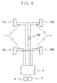
- the apparatus is provided with normal rotational information detecting means each provided in relation with each tire W i and with a lateral acceleration (lateral G) sensor SS for detecting acceleration in lateral directions of the vehicle.
- a positive value is defined in case this lateral C acts on the left side with respect to a moving direction.
- the lateral G sensor SS may be a piezoelectric or strain gauge type acceleration converted. It should be noted that it is alternatively possible to employ a yaw rate sensor instead of the lateral G sensor for obtaining the lateral G on the basis of values obtained by this sensor.
- a system for controlling spinning movements or similar during running for the purpose of stabilising the posture of the vehicle is provided as it is in the case with some of the currently available vehicles, it is possible to use an acceleration sensor or yaw rate sensor mounted on the vehicle.
- the calculating processing means and judged value correcting means of the present Embodiment 3 are included in the control unit 2.
- the accuracy of the DWS can be improved on the basis of lateral G obtained by the lateral G sensor and it is thus possible to detect decompression of a tyre in a more rapid manner.
- the constant 1 and constant 2 of the above equation (3) of Embodiment 3 may be obtained by calculating the vehicle speed obtained by the speed sensor of the vehicle, the lateral G obtained by the lateral G sensor, the DEL and the DFR while making the vehicle run on a curve with the tyres being at normal internal pressure.
- a domestic 3,000 cc FF vehicle was provided with a lateral G sensor mounted on a central portion of the vehicle body which was connected to a personal computer. Values of the lateral G were thus arranged to be stored on software within the personal computer. In this manner, the wheel speed of the four wheels and values of the lateral G sensor could directly be stored and reflected in the equation (3) for performing cornering correction.
- the vehicle was made to run under the following five conditions on a public mountain road, on a course made to perform stationary turns and on a test course.
- the present invention is so arranged to obtain an accurate turning radius also in case any tyre of the following wheels is decompressed by correcting the turning radius obtained on the basis of rotational information by using the steering angle information, the DEL value might be obtained in a more accurate manner than compared to conventional arrangements. It is further possible to detect decompression and issue alarm also in case both tyres on either side of the right and left wheels are simultaneously in a decompressed condition.
- a decompressed condition of a tyre can be determined also in case any tyre of the following wheels or the driving wheels is decompressed.
- cornering correction might be performed in an accurate manner without being affected by a decompressed condition of a tyre. It is accordingly possible to improve the accuracy of detecting decompression of a tyre.
Abstract
Description
i: 1=front left tyre, 2=front right tyre, 3-rear left tyre, and 4-rear right tyre.
- 1:
- normal internal pressure
- 2:
- tyre air pressure of front left tyre decompressed by 30%
- 3:
- tyre air pressure of front right tyre decompressed by 40%
- 4:
- tyre air pressure of rear left tyre decompressed by 30%
- 5:
- tyre air pressure of rear right tyre decompressed by 40%
Claims (10)
- An apparatus for alarming decrease in tyre air pressure based on rotational information obtained from tyres attached to a four-wheeled vehicle, comprising: a rotational information detecting means (1) for detecting rotational information of each tyre; a steering angle detecting means (S) for detecting a steering angle; a memory means (2c) for storing the rotational information of each tyre and the steering angle; a turning radius calculating and processing means (2) for calculating a turning radius based on the rotational information of each tyre; a judged value calculating and processing means for calculating a judged value based on the rotational information of each tyre; and a correction means for correcting the turning radius in case it has been determined by the steering angle detecting means that the vehicle is in a straight-ahead driving condition though the driving condition of the vehicle is a turning condition when being based on the turning radius obtained on the basis of the rotational information.
- An apparatus for alarming decrease in tyre air pressure based on rotational information obtained from tyres attached to a four-wheeled vehicle, comprising: a rotational information detecting means (1) for detecting rotational information of each tyre; a steering angle detecting means (S) for detecting a steering angle; a memory means (2c) for storing the rotational information of each tyre and the steering angle; a turning radius calculating and processing means for calculating a turning radius based on the rotational information of each tyre; a correction means for correcting the turning radius in case it has been determined by the steering angle detecting means (S) that the vehicle is in a straight-ahead driving condition though the driving condition of the vehicle is a turning condition when being based on the turning radius obtained on the basis of the rotational information; and a decompression determining means for determining a decompressed condition of a tyre in case a correction coefficient for the turning radius as obtained by the correction means is not less than a threshold.
- The apparatus of Claim 2, wherein the threshold is an integrated value in a predetermined time.
- A method for alarming decrease in the tyre air pressure based on rotational information obtained from tyres attached to a four-wheeled vehicle, comprising the steps of: detecting rotational information (Wi) of each tyre; detecting a steering angle; storing the rotational information of each tyre and the steering angle; calculating a reciprocal of a turning radius based on the rotational information of each tyre; calculating a judged value based on the rotational information of each tyre; and correcting, when performing correction of the judged value for decompressed condition due to cornering, the turning radius in case it has been determined on the basis of the steering angle that the vehicle is in a straight-ahead driving condition though the driving condition of the vehicle is a turning condition when being based on the turning radius obtained on the basis of the rotational information.
- A method for alarming decrease in tyre air pressure based on rotational information obtained from tyres attached to a four-wheeled vehicle, comprising the steps of: detecting rotational information (Wi) of each tyre; detecting a steering angle; storing the rotational information of each tyre and the steering angle; calculating a turning radius based on the rotational information of each tyre; correcting the turning radius in case it has been determined on the basis of the steering angle that the vehicle is in a straight-ahead driving condition when being based on the turning radius obtained on the basis of the rotational information; and determining a decompressed condition of a tyre in case a correction coefficient for the turning radius as obtained during the correction process is not less than a threshold.
- The method of Claim 5, wherein the threshold is an integrated value in a predetermined time.
- An apparatus for alarming decrease in tyre air pressure based on rotational information obtained from tyres attached to a four-wheeled vehicle, comprising: a rotational information detecting means (1) for detecting rotation information (Wi) of each tyre; a memory means (2c) for storing the rotational information of each tyre; a calculating and processing means (2) for calculating a judged value based on the rotational information of each tyre; and a judged value correcting means for correcting the judged value based on a lateral acceleration obtained through a lateral acceleration sensor (SS) provided in the vehicle.
- An apparatus for alarming decrease in tyre air pressure based on rotational information (Wi) obtained from tyres attached to a four-wheeled vehicle, comprising: a rotation information detecting means (i) for detecting rotational information (Wi) of each tyre; a memory means (2c) for storing the rotational information of each tyre; a calculating and processing means (2) for calculating a judged value based on the rotational information of each tyre; and a judged value correcting means for correcting the judged value based on a lateral acceleration obtained on a basis of values of a yaw rate sensor provided in the vehicle.
- A method for alarming decrease in tyre air pressure based on rotational information (Wi) obtained from tyres attached to a four-wheeled vehicle, comprising the steps of: detecting rotational information (Wi) of each tyre; storing the rotational information of each tyre; calculating a judged value based on the rotational information of each tyre; and correcting the judged value based on a lateral acceleration obtained through a lateral acceleration sensor provided in the vehicle.
- A method for alarming decrease in tyre air pressure based on rotational information (Wi) obtained from tyres attached to a four-wheeled vehicle, comprising the steps of: detecting rotational information (Wi) of each tyre; storing the rotational information (Wi) of each tyre; calculating a judged value based on the rotational information of each tyre; and correcting the judged value based on a lateral acceleration obtained on a basis of values of a yaw rate sensor provided in the vehicle.
Applications Claiming Priority (4)
| Application Number | Priority Date | Filing Date | Title |
|---|---|---|---|
| JP2000186129A JP3626076B2 (en) | 2000-06-21 | 2000-06-21 | Tire pressure drop alarm device and method |
| JP2000186129 | 2000-06-21 | ||
| JP2000199106A JP3605006B2 (en) | 2000-06-30 | 2000-06-30 | Tire pressure drop warning device and method |
| JP2000199106 | 2000-06-30 |
Publications (3)
| Publication Number | Publication Date |
|---|---|
| EP1167086A2 true EP1167086A2 (en) | 2002-01-02 |
| EP1167086A3 EP1167086A3 (en) | 2004-02-11 |
| EP1167086B1 EP1167086B1 (en) | 2009-12-09 |
Family
ID=26594357
Family Applications (1)
| Application Number | Title | Priority Date | Filing Date |
|---|---|---|---|
| EP01305387A Expired - Lifetime EP1167086B1 (en) | 2000-06-21 | 2001-06-21 | Method for alarming decrease in tyre air pressure and apparatus used therefor |
Country Status (3)
| Country | Link |
|---|---|
| US (1) | US6420966B2 (en) |
| EP (1) | EP1167086B1 (en) |
| DE (1) | DE60140716D1 (en) |
Cited By (2)
| Publication number | Priority date | Publication date | Assignee | Title |
|---|---|---|---|---|
| WO2007010006A1 (en) * | 2005-07-22 | 2007-01-25 | Continental Teves Ag & Co Ohg | Method for improving a tyre-pressure monitoring system |
| WO2008017527A1 (en) * | 2006-08-10 | 2008-02-14 | Continental Automotive Gmbh | Method and apparatus for operating a vehicle |
Families Citing this family (23)
| Publication number | Priority date | Publication date | Assignee | Title |
|---|---|---|---|---|
| US8266465B2 (en) | 2000-07-26 | 2012-09-11 | Bridgestone Americas Tire Operation, LLC | System for conserving battery life in a battery operated device |
| US7161476B2 (en) | 2000-07-26 | 2007-01-09 | Bridgestone Firestone North American Tire, Llc | Electronic tire management system |
| FR2814238B1 (en) * | 2000-09-15 | 2004-06-25 | Dufournier Technologies S A S | METHOD AND SYSTEM OR CENTRAL FOR MONITORING THE CONDITION OF TIRES, AND DETECTION OF THE PRESENCE OF CHAINS OR SNOW NAILS, ON A VEHICLE |
| JP3605026B2 (en) * | 2000-10-31 | 2004-12-22 | 住友ゴム工業株式会社 | Tire pressure drop warning device and method |
| JP3869685B2 (en) * | 2001-06-20 | 2007-01-17 | 住友ゴム工業株式会社 | Two-wheeled vehicle air pressure drop detecting device and method, and two-wheeled vehicle decompression determination program |
| EP1406774B1 (en) * | 2001-07-09 | 2008-01-16 | Continental Teves AG & Co. oHG | System and method for monitoring tire pressure in motor vehicles |
| DE10137591B4 (en) * | 2001-08-01 | 2005-07-14 | Daimlerchrysler Ag | Telemetric tire pressure monitoring system |
| JP3923808B2 (en) * | 2002-01-23 | 2007-06-06 | 住友ゴム工業株式会社 | Tire pressure drop warning method and apparatus, and tire decompression determination program |
| JP2003220811A (en) * | 2002-01-30 | 2003-08-05 | Sumitomo Rubber Ind Ltd | Method and device for detecting tire pneumatic pressure drop and program of judging tire pressure drop |
| JP3801945B2 (en) * | 2002-04-02 | 2006-07-26 | 住友ゴム工業株式会社 | Tire pressure drop detection method and apparatus, and tire decompression determination program |
| JP3869762B2 (en) * | 2002-06-13 | 2007-01-17 | 住友ゴム工業株式会社 | Tire pressure drop detection method and apparatus, and tire decompression determination program |
| US20040225423A1 (en) * | 2003-05-07 | 2004-11-11 | Carlson Christopher R. | Determination of operational parameters of tires in vehicles from longitudinal stiffness and effective tire radius |
| JP3971720B2 (en) * | 2003-06-09 | 2007-09-05 | 住友ゴム工業株式会社 | Tire pressure drop detection method and apparatus, and tire decompression determination program |
| DE602004029642D1 (en) * | 2003-11-25 | 2010-12-02 | Sumitomo Rubber Ind | Method and apparatus for detecting pressure drop in tires, and program for assessing pressure drop in tires |
| JP4028848B2 (en) * | 2004-01-21 | 2007-12-26 | 住友ゴム工業株式会社 | Tire pressure drop detection method and apparatus, and tire decompression determination program |
| JP2005321958A (en) * | 2004-05-07 | 2005-11-17 | Denso Corp | Tire air pressure detection device |
| JP4217197B2 (en) * | 2004-08-11 | 2009-01-28 | 住友ゴム工業株式会社 | Judgment method of vehicle loading conditions |
| DE102005004833A1 (en) * | 2005-02-02 | 2006-08-10 | Global Dynamix Ag | Tire pressure monitoring device and tire air pressure control method |
| JP4244354B2 (en) * | 2006-07-20 | 2009-03-25 | 住友ゴム工業株式会社 | Tire pressure drop warning method, apparatus and program |
| JP2008249523A (en) * | 2007-03-30 | 2008-10-16 | Sumitomo Rubber Ind Ltd | Method, device and program for alarming abnormal drop in tire pneumatic pressure |
| CN104924864B (en) * | 2015-05-18 | 2017-09-29 | 北京新能源汽车股份有限公司 | A kind of pure electric automobile tire pressure monitoring method |
| DE102016214953A1 (en) * | 2016-08-11 | 2018-02-15 | Robert Bosch Gmbh | Method and device for checking the pneumatic tire pressure of a bicycle |
| CN108454327B (en) * | 2018-01-26 | 2020-11-20 | 深圳市元征科技股份有限公司 | Tire pressure detection method, device and terminal |
Citations (2)
| Publication number | Priority date | Publication date | Assignee | Title |
|---|---|---|---|---|
| EP0646481A1 (en) | 1993-09-30 | 1995-04-05 | Honda Giken Kogyo Kabushiki Kaisha | Pneumatic tire pressure change detecting system |
| EP0826968A1 (en) | 1996-03-14 | 1998-03-04 | Sumitomo Electric Industries, Ltd. | Initial correction factor computing apparatus and apparatus utilizing the same |
Family Cites Families (8)
| Publication number | Priority date | Publication date | Assignee | Title |
|---|---|---|---|---|
| US5591906A (en) * | 1992-09-16 | 1997-01-07 | Sumitomo Electric Industries, Ltd. | Tire pressure drop detecting device and method |
| JP3050026B2 (en) * | 1993-12-22 | 2000-06-05 | 三菱自動車工業株式会社 | Tire pressure drop detection method |
| JP2749784B2 (en) * | 1994-11-21 | 1998-05-13 | 住友電気工業株式会社 | Turning radius calculation method and turning radius calculation device |
| JP3175552B2 (en) * | 1995-08-04 | 2001-06-11 | 株式会社デンソー | Tire pressure estimation device |
| JP3119809B2 (en) * | 1996-01-26 | 2000-12-25 | 住友電気工業株式会社 | Method and apparatus for detecting decrease in tire air pressure |
| JP3333691B2 (en) * | 1996-09-25 | 2002-10-15 | 株式会社日本自動車部品総合研究所 | Tire pressure detector |
| US5764137A (en) * | 1996-12-09 | 1998-06-09 | Chrysler Corporation | System and method for diagnosing loss of pressure in tires of a vehicle |
| US6137400A (en) * | 1997-08-22 | 2000-10-24 | Sumitomo Rubber Industries, Ltd. | Apparatus and method for detecting decrease in tire air-pressure |
-
2001
- 2001-06-21 DE DE60140716T patent/DE60140716D1/en not_active Expired - Lifetime
- 2001-06-21 EP EP01305387A patent/EP1167086B1/en not_active Expired - Lifetime
- 2001-06-21 US US09/885,128 patent/US6420966B2/en not_active Expired - Lifetime
Patent Citations (2)
| Publication number | Priority date | Publication date | Assignee | Title |
|---|---|---|---|---|
| EP0646481A1 (en) | 1993-09-30 | 1995-04-05 | Honda Giken Kogyo Kabushiki Kaisha | Pneumatic tire pressure change detecting system |
| EP0826968A1 (en) | 1996-03-14 | 1998-03-04 | Sumitomo Electric Industries, Ltd. | Initial correction factor computing apparatus and apparatus utilizing the same |
Cited By (4)
| Publication number | Priority date | Publication date | Assignee | Title |
|---|---|---|---|---|
| WO2007010006A1 (en) * | 2005-07-22 | 2007-01-25 | Continental Teves Ag & Co Ohg | Method for improving a tyre-pressure monitoring system |
| DE102006033589B4 (en) | 2005-07-22 | 2021-08-05 | Continental Teves Ag & Co. Ohg | Method for improving a tire pressure monitoring system |
| WO2008017527A1 (en) * | 2006-08-10 | 2008-02-14 | Continental Automotive Gmbh | Method and apparatus for operating a vehicle |
| US8280587B2 (en) | 2006-08-10 | 2012-10-02 | Continental Automotive Gmbh | Method and apparatus for operating a vehicle |
Also Published As
| Publication number | Publication date |
|---|---|
| EP1167086B1 (en) | 2009-12-09 |
| EP1167086A3 (en) | 2004-02-11 |
| DE60140716D1 (en) | 2010-01-21 |
| US6420966B2 (en) | 2002-07-16 |
| US20020011929A1 (en) | 2002-01-31 |
Similar Documents
| Publication | Publication Date | Title |
|---|---|---|
| EP1167086A2 (en) | Method for alarming decrease in tyre air pressure and apparatus used therefor | |
| US5343741A (en) | System for determining pneumatic tire pressure for motor vehicle by comparing actual to adequate wheel rotational speed | |
| JP2749784B2 (en) | Turning radius calculation method and turning radius calculation device | |
| EP1145875B1 (en) | Apparatus and method for alarming decrease in tyre air pressure | |
| EP1352765A2 (en) | Method and apparatus for detecting decrease in tire-pressure and program for judging decompression of tire | |
| US7032442B2 (en) | Method and apparatus for detecting decrease in tire air-pressure and program for judging decompression of tire | |
| EP0970823A2 (en) | Apparatus for identifying tyres and method thereof | |
| JP3277026B2 (en) | Tire pressure detection method | |
| JP4266266B2 (en) | Tire pressure drop alarm device and method | |
| EP1332895B1 (en) | Method and apparatus for detecting decrease in tire air-pressure | |
| US6907327B2 (en) | Method of detection of limited slip differential device, method and apparatus for detecting decrease in tire air-pressure employing the method of detection, and program for judging decompression of tire | |
| US6756891B2 (en) | Method and apparatus for detecting decrease in tire air-pressure, and selecting program for the thresholds for judging decompression of tire | |
| JPH06297923A (en) | Tire pneumatic pressure detecting device | |
| US7395145B2 (en) | Apparatus and method for calculating initial correction coefficient, and program for calculating initial correction coefficient | |
| JP4004990B2 (en) | Slip ratio calculation method, tire pressure drop detection method and apparatus, slip ratio calculation program, and tire decompression determination program | |
| JP2004203214A (en) | Method and device for detecting drop of pneumatic pressure of tire and program for determining pressure drop of tire | |
| JP2004017717A (en) | Method and device for detecting decrease of air pressure of tire, and program for determining pressure reduction of tire | |
| JP3626076B2 (en) | Tire pressure drop alarm device and method | |
| JP3605006B2 (en) | Tire pressure drop warning device and method | |
| JP3050026B2 (en) | Tire pressure drop detection method | |
| JP3594833B2 (en) | Tire air pressure drop warning method and device | |
| JP3957656B2 (en) | Tire pressure drop detection method and apparatus, and tire decompression determination program | |
| JP3643045B2 (en) | Tire pressure abnormality alarm device and method, and initialization operation start program | |
| JPH10100620A (en) | Tire air pressure lowering detecting method and device thereof | |
| JPH0966714A (en) | Method and device for detecting reduction in tire air pressure |
Legal Events
| Date | Code | Title | Description |
|---|---|---|---|
| PUAI | Public reference made under article 153(3) epc to a published international application that has entered the european phase |
Free format text: ORIGINAL CODE: 0009012 |
|
| AK | Designated contracting states |
Kind code of ref document: A2 Designated state(s): AT BE CH CY DE DK ES FI FR GB GR IE IT LI LU MC NL PT SE TR |
|
| AX | Request for extension of the european patent |
Free format text: AL;LT;LV;MK;RO;SI |
|
| PUAL | Search report despatched |
Free format text: ORIGINAL CODE: 0009013 |
|
| AK | Designated contracting states |
Kind code of ref document: A3 Designated state(s): AT BE CH CY DE DK ES FI FR GB GR IE IT LI LU MC NL PT SE TR |
|
| AX | Request for extension of the european patent |
Extension state: AL LT LV MK RO SI |
|
| AKX | Designation fees paid |
Designated state(s): DE FR GB |
|
| 17P | Request for examination filed |
Effective date: 20040331 |
|
| GRAP | Despatch of communication of intention to grant a patent |
Free format text: ORIGINAL CODE: EPIDOSNIGR1 |
|
| GRAS | Grant fee paid |
Free format text: ORIGINAL CODE: EPIDOSNIGR3 |
|
| GRAA | (expected) grant |
Free format text: ORIGINAL CODE: 0009210 |
|
| RIN1 | Information on inventor provided before grant (corrected) |
Inventor name: SUGISAWA, TOSHIFUMI.C/O SUMITOMO RUBBER INDUSTRIES |
|
| RAP1 | Party data changed (applicant data changed or rights of an application transferred) |
Owner name: SUMITOMO RUBBER INDUSTRIES LIMITED Owner name: SUMITOMO ELECTRIC INDUSTRIES, LTD. |
|
| AK | Designated contracting states |
Kind code of ref document: B1 Designated state(s): DE FR GB |
|
| REG | Reference to a national code |
Ref country code: GB Ref legal event code: FG4D |
|
| REF | Corresponds to: |
Ref document number: 60140716 Country of ref document: DE Date of ref document: 20100121 Kind code of ref document: P |
|
| PLBE | No opposition filed within time limit |
Free format text: ORIGINAL CODE: 0009261 |
|
| STAA | Information on the status of an ep patent application or granted ep patent |
Free format text: STATUS: NO OPPOSITION FILED WITHIN TIME LIMIT |
|
| 26N | No opposition filed |
Effective date: 20100910 |
|
| GBPC | Gb: european patent ceased through non-payment of renewal fee |
Effective date: 20100621 |
|
| PG25 | Lapsed in a contracting state [announced via postgrant information from national office to epo] |
Ref country code: GB Free format text: LAPSE BECAUSE OF NON-PAYMENT OF DUE FEES Effective date: 20100621 |
|
| REG | Reference to a national code |
Ref country code: FR Ref legal event code: PLFP Year of fee payment: 16 |
|
| REG | Reference to a national code |
Ref country code: FR Ref legal event code: PLFP Year of fee payment: 17 |
|
| REG | Reference to a national code |
Ref country code: FR Ref legal event code: PLFP Year of fee payment: 18 |
|
| PGFP | Annual fee paid to national office [announced via postgrant information from national office to epo] |
Ref country code: DE Payment date: 20190612 Year of fee payment: 19 |
|
| PGFP | Annual fee paid to national office [announced via postgrant information from national office to epo] |
Ref country code: FR Payment date: 20190510 Year of fee payment: 19 |
|
| REG | Reference to a national code |
Ref country code: DE Ref legal event code: R119 Ref document number: 60140716 Country of ref document: DE |
|
| PG25 | Lapsed in a contracting state [announced via postgrant information from national office to epo] |
Ref country code: FR Free format text: LAPSE BECAUSE OF NON-PAYMENT OF DUE FEES Effective date: 20200630 |
|
| PG25 | Lapsed in a contracting state [announced via postgrant information from national office to epo] |
Ref country code: DE Free format text: LAPSE BECAUSE OF NON-PAYMENT OF DUE FEES Effective date: 20210101 |