EP1168029A2 - Optical image separation system and confocal scanner unit - Google Patents
Optical image separation system and confocal scanner unit Download PDFInfo
- Publication number
- EP1168029A2 EP1168029A2 EP00116790A EP00116790A EP1168029A2 EP 1168029 A2 EP1168029 A2 EP 1168029A2 EP 00116790 A EP00116790 A EP 00116790A EP 00116790 A EP00116790 A EP 00116790A EP 1168029 A2 EP1168029 A2 EP 1168029A2
- Authority
- EP
- European Patent Office
- Prior art keywords
- light
- dichroic mirror
- confocal
- optical image
- image separation
- Prior art date
- Legal status (The legal status is an assumption and is not a legal conclusion. Google has not performed a legal analysis and makes no representation as to the accuracy of the status listed.)
- Ceased
Links
Images


Classifications
-
- G—PHYSICS
- G02—OPTICS
- G02B—OPTICAL ELEMENTS, SYSTEMS OR APPARATUS
- G02B21/00—Microscopes
- G02B21/0004—Microscopes specially adapted for specific applications
- G02B21/002—Scanning microscopes
- G02B21/0024—Confocal scanning microscopes (CSOMs) or confocal "macroscopes"; Accessories which are not restricted to use with CSOMs, e.g. sample holders
- G02B21/0036—Scanning details, e.g. scanning stages
- G02B21/0044—Scanning details, e.g. scanning stages moving apertures, e.g. Nipkow disks, rotating lens arrays
-
- G—PHYSICS
- G02—OPTICS
- G02B—OPTICAL ELEMENTS, SYSTEMS OR APPARATUS
- G02B21/00—Microscopes
- G02B21/0004—Microscopes specially adapted for specific applications
- G02B21/002—Scanning microscopes
- G02B21/0024—Confocal scanning microscopes (CSOMs) or confocal "macroscopes"; Accessories which are not restricted to use with CSOMs, e.g. sample holders
- G02B21/0052—Optical details of the image generation
Definitions
- the present invention is related to an optical system in a confocal microscopic observation system. More particularly, the present invention relates to an optical image separation system connected to the confocal image output port of a Nipkow disk type confocal scanner.
- FIG. 1 shows an example of Nipkow disk type confocal scanners used with a microscope.
- confocal scanner 100 is connected to microscope 200.
- Illuminating parallel excitation flux 1 (chain line) is converged into individual fluxes by micro lens array disk (hereafter called “ML disk") 2, and passed through individual pinholes of pinhole array disk (hereafter called “Nipkow disk”) 4 after being transmitted through dichroic mirror (hereafter called “DM”) 3.
- ML disk micro lens array disk
- Nipkow disk pinhole array disk
- DM dichroic mirror
- Flux 1 is then focused on sample 6 by objective lens 5 of the microscope.
- Fluorescence signal 7 (continuous line) emitted from sample 6 is transmitted again through objective lens 5 and is focused on individual pin holes of Nipkow disk 4.
- Fluorescence signal 7 passed through the individual pinholes is reflected by DM 3 and forms a fluorescence image on two-dimensional sensor 10 by relay lens 9.
- DM 3 is designed so as to transmit excitation
- ML disk 2 and Nipkow disk 4 turn around rotating shaft 11, both being mechanically connected to each other by member 8.
- individual micro-lenses and pinholes formed on Nipkow disk 4 are arranged so that the individual pinholes scan over plane 12 to be observed on sample 6.
- the plane on which pinholes of Nipkow disk 4 are arranged, plane 12 to be observed on sample 6, and light detecting surface of two-dimensional sensor 10 are arranged in optically conjugate relation with each other. Accordingly, an optical sectional image of sample 6, that is, a confocal image is formed on two-dimensional sensor 10.
- a Nipkow disk type confocal scanner uses a two-dimensional sensor.
- a confocal image of sample 6 can be formed on the light detecting surface of two-dimensional sensor 10 in a short time by rotating ML disk 2 and Nipkow disk 4 together at a high speed.
- This makes it possible to acquire at a high speed confocal images of all samples 60, on which many specimens to be inspected are arranged in a matrix as shown in Figure 2, moving them relative to the microscope and the confocal scanner.
- the above confocal scanners are used for a screening technique in developing new medicines .
- a sample emitting sufficiently bright fluorescence signals is used as the object of inspection, use of the above-described ML disk 2 is not needed sometimes.
- a problem of the number of samples that can be processed per unit time in a screening method shown in Figure 2 that is, a problem of throughput does not occur, as long as cases are limited to those where a sample emits only one type of fluorescence.
- a screening method according to the multiple-staining technique is used, in which a plurality of fluorescence wavelengths different depending on sample reactions can be detected by adding separate fluorescence reagents having different fluorescence wavelengths to each specimen of sample 60 or adding a plurality of types of fluorescence reagent to all specimens.
- sample 60 total number of specimens arranged in a matrix
- a DM that has a specific reflection characteristic and can detect the first fluorescence wavelength.
- the total number of specimens must be again inspected. Consequently, since it is necessary to repeat DM replacement and inspection of the total number of specimens by the number of required types of wavelengths, there is a problem that throughput is reduced.
- Sample 60n+1 for which inspection for fluorescence wavelength ⁇ n+1 in inspection system n+1 comprising microscope 200n+1, scanner 100n+1 and two-dimensional sensor 10n+1 is completed is sent to inspection system n+2. That is, samples for which inspection in each inspection system is completed are sent to next inspection systems respectively. For this reason, however, there is the problem that this method can hold the throughput high but the cost also becomes high because a plurality of confocal scanners, microscopes, etc. is necessary.
- the present invention is proposed in consideration of the above-described conditions. It relates to an optical image separation system used by being connected to a Nipkow disk type confocal scanner. Its objective is to provide an optical image separation system that can detect the return light from a sample by separating it into a plurality of different wavelength regions without repeating DM replacement and inspection of the total number of specimens by the required number of wavelength types or without using a plurality of confocal scanners and microscopes as in prior arts, and thus can hold the throughput high without increasing the cost.
- the present invention provides an optical image separation system connected to the confocal image output port of a Nipkow disk type confocal scanner for achieving the above described objectives; the optical image separation system comprising a return light separating means that separates the light returned from a sample and emitted from the above confocal image output port into light beams in a plurality of wavelength regions or a plurality of portions of the same wavelength region.
- the above confocal image output port means all the ports, such as camera port, eye port, spectral port, etc. for emitting confocal image information formed by passing the return light from a sample through a Nipkow disk from the inside of a confocal scanner to the outside.
- the return light from a sample, emitted from the confocal image output port of a confocal scanner can be separated into any light beams in a plurality of wavelength regions or a plurality of portions of the same wavelength region by the return light separating means. Accordingly, confocal images for every wavelength region separated arbitrarily or for every portion of the same wavelength regions can be acquired simultaneously and at a high speed without deterioration of resolution and without the following operations as in prior arts: repeating DM replacement and inspection of the total number of specimens by the required number of wavelength types, or using a plurality of sets of confocal scanners and microscopes.
- the return light separating means of the optical image separation system of the present invention may be those in which, the return light from a sample emitted from the confocal image output port of a confocal scanner is separated into the light beams in a plurality of wavelength regions and at least one of the separated light beams is again separated into a plurality of portions of the same wavelength region, or the above return light from the sample is separated into a plurality of portions of the same wavelength region and at least one of the separated light beams is again separated into light beams in a plurality of wavelength regions.
- Nipkow disk type confocal scanners to which the optical image separation system of the present invention is connected, for example, those described in (a) to (d) below can be listed, but they are not limited to those.
- optical image separation system of the present invention can adopt the following types of configuration (1) to (8):
- optical image separation systems of the present invention can be connected respectively to each confocal image output port of a confocal scanner having a plurality of confocal image output ports.
- a plurality of such optical image separation systems concatenated together can also be connected to a confocal image output port of a confocal scanner. Accordingly, the present invention provides confocal scanner units shown in (a) and (b) below.
- Figure 1 shows a configuration drawing indicating an example of conventional confocal scanners used with a microscope.
- Figure 2 shows a configuration drawing indicating another example of conventional confocal scanners used with a microscope.
- Figure 3 shows a configuration drawing indicating an example of conventional screening methods using a confocal scanner.
- Figure 4 shows a configuration drawing indicating a first embodiment of the present invention.
- Figure 5 shows a graph indicating the spectral response of the dichroic mirror of the Nipkow disk type confocal scanner used in the first embodiment.
- Figure 6 shows a graph indicating the spectral response of the dichroic mirror of the optical image separation system used in the first embodiment.
- Figure 7 shows a graph indicating the spectral response of the barrier filter used in the first embodiment.
- Figure 8 shows a configuration drawing indicating a second embodiment of the present invention.
- Figure 9 shows a configuration drawing indicating a third embodiment of the present invention.
- Figure 10 shows a configuration drawing indicating a fourth embodiment of the present invention.
- Figure 11 shows a configuration drawing indicating a fifth embodiment of the present invention.
- Figure 12 shows a configuration drawing indicating a sixth embodiment of the present invention.
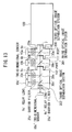
- Figure 13 shows a configuration drawing indicating a seventh embodiment of the present invention.
- FIG 4 shows a configuration drawing indicating the first embodiment of the present invention.
- Confocal scanner 100 is connected to a microscope.
- the fluxes pass through individual pinholes of Nipkow disk 4 after transmitting the first DM 3 composed of flat plate mirror having the spectral response shown in Figure 5, and are focused onto each specimen of sample 60 by objective lens 5 of the microscope to excite fluorescent reagents.
- a converging lens (not shown) may be used to construct an infinite optical system.
- numeral 300 shows an optical image separation system connected to confocal image output port 110 of confocal scanner 100.
- This optical image separation system 300 is provided with the second DM 30 composed of a flat plate mirror as the return light separating means and barrier filters 20a and 20b having the spectral response shown in Figure 4 as a stray light removing means.
- Each specimen of sample 60 is added with fluorescent reagents CY3 and CY5.
- Fluorescence signal 7 emitted by each fluorescent reagent again passes through objective lens 5 and is focused on individual pinholes of Nipkow disk 4.
- Fluorescence signal 7 passing through individual pinholes is reflected by DM 3 and emitted from confocal image output port 110 of confocal scanner 100 via relay lens 9 so that each image is formed on two-dimensional sensors 10a and 10b (detecting means).
- fluorescence signal 7 reflected by the above-described DM 3 reaches the second DM 30.
- DM 30 has the spectral response shown in Figure 6, the signal of wavelengths 660 nm to 720 nm of CY5 fluorescent components transmits through DM 30 and reaches two-dimensional sensor 10a after passing through barrier filter 20a having the spectral response shown in Figure 4, while the signal of wavelengths 550 nm to 630 nm of CY3 fluorescent components is reflected by DM 30 and reaches two-dimensional sensor 10b after passing through barrier filter 20b having the spectral response shown in Figure 7.
- Confocal optical image formed on Nipkow disk 4 is formed on two-dimensional sensors 10a and 10b by relay lens 9.
- an optical sectional image of sample 60 that is, a confocal image is formed on two-dimensional sensors 10a and 10b because the following planes are arranged in an optically conjugate relationship with each other:
- the confocal image of sample 60 can be formed simultaneously on the light-detecting surfaces of two-dimensional sensors 10a and 10b, confocal images that are selected and separated for any wavelength for all specimens can be acquired at a high speed by moving sample 60, on which a number of specimens to be inspected are arranged in a matrix, relative to the microscope and confocal scanner.
- the object of inspection is the specimens emitting sufficiently bright fluorescence signals, ML disk 2 may be omitted.
- barrier filters 20a and 20b having the spectral response shown in Figure 7 are used to prevent excitation stray light from reaching two-dimensional sensors mixed into the fluorescence signal. However, if the fluorescence signal is sufficiently larger than excitation stray light signals, barrier filters may be omitted.
- Fluorescent reagents used in this embodiment are not limited to CY3 and CY5; any fluorescent reagents can be selected by making the DM have a spectral response for wavelengths corresponding to the combination of reagents.
- the fluorescent pigments (excitation wavelength peak [nm]/fluorescence wavelength peak [nm]) are listed below as an example.
- techniques to integrate proteins that emit specific fluorescence respectively to be expressed with gene manipulation may be used.
- Figure 8 shows a configuration drawing indicating the second embodiment of the present invention.
- This embodiment improves, in optical image separation system 300, the aberration in barrier filters 20a and 20b and the degree of positional freedom of two-dimensional sensors 10a and 10b on each optical axis by positioning relay lenses 9a and 9b (image-forming optical system) between DM 30 and two-dimensional sensors 10a and 10b respectively.
- Relay lenses 9a and 9b may have different shapes and focal lengths.
- Figure 9 shows a configuration drawing indicating the third embodiment of the present invention.
- the same components as those of Figure 4 are given the same symbol and overlapping description will be omitted.
- This embodiment shows an example in which, in optical image separation system 300, the second DM 30 is a prism mirror.
- the prism mirror has an advantage that it is easier to handle compared with flat plate mirrors.
- Figure 10 shows a configuration drawing indicating the fourth embodiment of the present invention.
- the second DM 30 is beam splitter 31 composed of a flat plate glass (or a prism) having the partial transmission characteristic without having the wavelength separation characteristic.
- Fluorescence signals split by beam splitter 31 have the same fluorescent spectrum and the images in which resolution, sensitivity, and the angle of view are varied can be acquired simultaneously on two two-dimensional sensors 10a and 10b.
- partial transmittance is mainly used with a ratio of 50:50 in many cases, the flat plate glass can be used with any partial transmittance not limited to this range.
- Figure 11 shows a configuration drawing indicating the fifth embodiment of the present invention.
- the same components as those of Figure 1 are given the same symbol and overlapping description will be omitted.
- This embodiment shows an example in which, in optical image separation system 300, the second DM 30 is a diffraction grating (or spectral prism) 32 having a wavelength separation characteristic. This embodiment can select any wavelength by changing the angle of incidence of fluorescence signal 7 to diffraction grating (or spectral prism) 32.
- Figure 12 shows a configuration drawing indicating the sixth embodiment of the present invention.
- This embodiment shows an example in which, in optical image separation system 300, the second DM 30a, the third DM 30b (return light separating means), and relay lenses 9a, 9b, and 9c (image-forming optical system) are arranged and confocal fluorescence images having each of the wavelengths separated into three by two-dimensional sensors 10a, 10b, and 10c (detecting means) are acquired simultaneously.
- Figure 13 shows a configuration drawing indicating the seventh embodiment of the present invention.
- This embodiment shows an example in which the first, second, and third optical image separation systems 300, 301, and 302 are concatenated with each other via ports 111 and 112 and these systems are connected to confocal image output port 110 of confocal scanner 100.
- wavelength component ⁇ a is separated from confocal fluorescence signal 7 emitted from confocal image output port 110 of confocal scanner 100 by DM 30a placed in first optical image separation system 300, the excitation stray light component is removed with barrier filter 20a, and then an image is formed on two-dimensional sensor 10a by relay lens 9a.
- wavelength component ⁇ b is separated from the fluorescence signal component that has transmitted through DM 30a by DM 30b placed in second optical image separation system 301, the excitation stray light component is removed with barrier filter 20b, and then another image is formed on two-dimensional sensor 10b by relay lens 9b.
- wavelength component ⁇ c is separated from the fluorescence signal component that has transmitted through DM 30b by DM 30c placed in third optical image separation system 302, the excitation stray light component is removed with barrier filter 20c, and then the third image is formed on two-dimensional sensor 10c by relay lens 9c.
- wavelength component ⁇ c' of the fluorescence signal component that has transmitted through DM 30c is separated by DM 30c' placed in third optical image separation system 302 and its image is formed on two-dimensional sensor 10c' by relay lens 9c' after the excitation stray light component is removed by barrier filter 20c'.
- An image of all the fluorescence signal components that have transmitted through DM 30c' is formed in two-dimensional sensor 10c" by relay lens 9c" after the excitation stray light component is removed by barrier filter 20c" placed in third optical image separation system 302.
- any wavelength separation for a fluorescence wavelength component can be easily carried out and confocal images of different wavelength components can be simultaneously observed by concatenating optical image separation systems, each provided with a DM or DMs having a characteristic to separate a required wavelength component as required, and by connecting them to a confocal image output port of a confocal scanner.
- the light returned from a sample and emitted from the confocal image output port of a confocal scanner can be separated into light beams in a plurality of any wavelength regions or to a plurality of portions of the same wavelength region. Therefore, confocal images for every arbitrarily separated wavelength region or every portion of the same wavelength region can be acquired simultaneously at a high speed without deteriorating the resolution, and without repeating DM replacement and inspection of the total number of specimens by the number of required wavelengths or without using a plurality of confocal scanners and microscopes.
- the configuration of the optical image separation system can be easily changed to meet a plurality of wavelength regions or a plurality of portions of the same wavelength region requiring separation.
Abstract
Description
using a plurality of sets of confocal scanners and microscopes.
the above return light from the sample is separated into a plurality of portions of the same wavelength region and at least one of the separated light beams is again separated into light beams in a plurality of wavelength regions.
each optical image separation system of the present invention being connected to each confocal image output port of the Nipkow disk type confocal scanner respectively.
a plurality of optical image separation systems of the present invention being concatenated with each other and connected to the confocal image output port of the Nipkow disk type confocal scanner.
Claims (15)
- An optical image separation system connected to the confocal image output port of a Nipkow disk type confocal scanner, provided with a return light separating means that separates the light returning from a sample, emitted from the above confocal image output port into light beams in a plurality of wavelength regions or a plurality of portions in the same wavelength region.
- An optical image separation system in accordance with claim 1, wherein said Nipkow disk type confocal scanner is provided with a dichroic mirror which transmits the light in a part of the incident light wavelength regions and reflects the light in the other part of the incident light wavelength regions, and a rotatable pinhole array disk which has a plurality of pinholes; andthe irradiating light from a light source being incident to the dichroic mirror,the light that transmits through the dichroic mirror and passes through the pinhole array disk is scanned over a sample, andthe return light from the sample that passes through the pinhole array disk being incident to the above dichroic mirror and emitted from said confocal image output port by reflecting a part or all of the relevant return light with the above dichroic mirror.
- An optical image separation system in accordance with claim 1, wherein said Nipkow disk type confocal scanner is provided with a dichroic mirror which transmits the light having the excitation light wavelengths in the incident light and reflects the light having fluorescence wavelengths in the incident light, and a rotatable pinhole array disk which has a plurality of pinholes; andthe irradiating light from a light source being incident to the dichroic mirror,the light that transmits through the dichroic mirror and passes through the pinhole array disk being scanned over a sample, andthe fluorescence from the sample that passes through the pinhole array disk being incident to the above dichroic mirror and emitted from said confocal image output port by reflecting a part or all of the relevant fluorescence with the above dichroic mirror.
- An optical image separation system in accordance with claim 1, wherein said Nipkow disk type confocal scanner is provided with a dichroic mirror which transmits the light in a part of the incident light wavelength regions and reflects the light in the other part of the incident light wavelength regions , and a rotatable pinhole array disk having a plurality of pinholes; andthe irradiating light from a light source is incident to the dichroic mirror,the light that is reflected from the dichroic mirror and passes through the pinhole array disk, being scanned over a sample, andthe return light from the sample that passes through the pinhole array disk being incident to the above dichroic mirror and emitted from said confocal image output port by transmitting a part or all of the relevant return light through the above dichroic mirror.
- An optical image separation system in accordance with claim 1, wherein said Nipkow disk type confocal scanner is provided with a dichroic mirror which reflects the light having the excitation light wavelengths in the incident light and transmits the light having fluorescence wavelengths in the incident light, and a rotatable pinhole array disk which has a plurality of pinholes; andthe irradiating light from a light source being incident to the dichroic mirror,the light that is reflected from the dichroic mirror and passes through the pinhole array disk being scanned over a sample, andthe fluorescence from the sample that passes through the pinhole array disk being incident to the above dichroic mirror and emitted from said confocal image output port by transmitting a part or all of the relevant fluorescence through the above dichroic mirror.
- An optical image separation system in accordance with any of claims 2 to 5, wherein the return light separating means is provided with one dichroic mirror or two or more dichroic mirrors for separating the return light, whose reflecting and transmitting characteristics are different from those of said Nipkow disk type confocal scanner dichroic mirror.
- An optical image separation system in accordance with claim 6, wherein the reflection wavelength bands of said return light separating dichroic mirror are contained in the reflection wavelength bands of said confocal scanner dichroic mirror.
- An optical image separation system in accordance with claim 6 or claim 7, wherein the transmission wavelength bands of said return light separating dichroic mirror are contained in the reflection wavelength bands of said confocal scanner dichroic mirror.
- An optical image separation system in accordance with any of claims 1 to 8, wherein an image-forming optical system is provided for detecting the light in a plurality of wavelength regions or a plurality of portions of the same wavelength region separated by the return light separating means with each detecting means.
- An optical image separation system in accordance with claim 9, wherein a stray light removing means is provided between the return light separating means and the detecting means;
the stray light removing means removing stray light from at least one of the light beams in a plurality of wavelength regions or a plurality of portions of the same wavelength region separated by the return light separating means. - An optical image separation system in accordance with any of claims 6 to 10, wherein one return light separating dichroic mirror or two or more return light separating dichroic mirrors are flat plate mirrors or prism mirrors respectively.
- An optical image separation system in accordance with claim 11, wherein a part or all of the flat plate mirrors or prism mirrors of the return light separating dichroic mirrors are replaced with flat plate glasses or prisms that have the partial transmission characteristic without having the wavelength separation characteristic.
- An optical image separation system in accordance with claim 11, wherein a part or all of the flat plate mirrors or prism mirrors of the return light separating dichroic mirrors are replaced with diffraction gratings or spectral prisms having the wavelength separation characteristic.
- A confocal scanner unit provided with a Nipkow disk type confocal scanner having a plurality of confocal image output ports and the optical image separation systems in accordance with any of claims 1 to 13,
the optical image separation systems being connected to a confocal image output port of the Nipkow disk type confocal scanner respectively. - A confocal scanner unit provided with a Nipkow disk type confocal scanner having a confocal image output port and optical image separation systems in accordance with any of claims 1 to 13,a plurality of the above optical image separation systems being concatenated with each other, andthese optical image separation systems concatenated with each other being connected to the confocal image output port of the Nipkow disk type confocal scanner.
Applications Claiming Priority (2)
| Application Number | Priority Date | Filing Date | Title |
|---|---|---|---|
| GB0015412 | 2000-06-23 | ||
| GB0015412A GB2363857A (en) | 2000-06-23 | 2000-06-23 | Nipkow disk confocal scanner with optical image separation system |
Publications (2)
| Publication Number | Publication Date |
|---|---|
| EP1168029A2 true EP1168029A2 (en) | 2002-01-02 |
| EP1168029A3 EP1168029A3 (en) | 2002-06-12 |
Family
ID=9894257
Family Applications (1)
| Application Number | Title | Priority Date | Filing Date |
|---|---|---|---|
| EP00116790A Ceased EP1168029A3 (en) | 2000-06-23 | 2000-08-03 | Optical image separation system and confocal scanner unit |
Country Status (4)
| Country | Link |
|---|---|
| US (1) | US6631029B2 (en) |
| EP (1) | EP1168029A3 (en) |
| JP (1) | JP2002062480A (en) |
| GB (1) | GB2363857A (en) |
Cited By (7)
| Publication number | Priority date | Publication date | Assignee | Title |
|---|---|---|---|---|
| EP1494058A1 (en) * | 2003-05-14 | 2005-01-05 | Riken | Confocal optical scanner |
| DE102007009551B3 (en) * | 2007-02-27 | 2008-08-21 | Ludwig-Maximilian-Universität | Device for the confocal illumination of a sample |
| EP2090882A2 (en) * | 2008-02-14 | 2009-08-19 | Yokogawa Electric Corporation | Drug discovery screening device |
| EP2317363A3 (en) * | 2009-10-26 | 2011-07-06 | Olympus Corporation | Microscope connecting unit and microscope system |
| DE102011083726A1 (en) * | 2011-09-29 | 2013-04-04 | Siemens Aktiengesellschaft | Confocal spectrometer and method of imaging in a confocal spectrometer |
| EP2594983A1 (en) * | 2005-02-21 | 2013-05-22 | Olympus Corporation | Low-light specimen image pickup unit and low-light specimen image pickup apparatus |
| EP2876480A1 (en) * | 2013-11-22 | 2015-05-27 | Olympus Corporation | Detection unit and confocal laser microscope |
Families Citing this family (7)
| Publication number | Priority date | Publication date | Assignee | Title |
|---|---|---|---|---|
| JP2002221663A (en) * | 2001-01-29 | 2002-08-09 | Nikon Corp | Scanning confocal microscope |
| US7280680B2 (en) | 2002-03-04 | 2007-10-09 | Riken | Method and apparatus for observing three-dimensional localizations of in vivo expressed genes as well as method and apparatus for observing minute three-dimensional localizations of in vivo expressed genes |
| DE602004031941D1 (en) * | 2003-05-30 | 2011-05-05 | Olympus Co | MEASURING DEVICE COMPRISING A LIGHT RECORDING UNIT |
| DE102004034997A1 (en) * | 2004-07-16 | 2006-02-02 | Carl Zeiss Jena Gmbh | Laser scanning microscope for capturing testing area, has moveable breaker plate provided for producing illumination, and detection-optical paths provided with interchangeable and/or switchable beam splitters and/or filters |
| JP2008076530A (en) * | 2006-09-19 | 2008-04-03 | Yokogawa Electric Corp | Microscope |
| JP2010145468A (en) * | 2008-12-16 | 2010-07-01 | Canon Inc | Height detection device and toner height detection apparatus using the same |
| JP6234109B2 (en) * | 2013-08-12 | 2017-11-22 | オリンパス株式会社 | Disk scanning device and microscope device |
Citations (5)
| Publication number | Priority date | Publication date | Assignee | Title |
|---|---|---|---|---|
| US5192980A (en) * | 1990-06-27 | 1993-03-09 | A. E. Dixon | Apparatus and method for method for spatially- and spectrally-resolved measurements |
| US5760950A (en) * | 1996-07-25 | 1998-06-02 | Advanced Scanning, Ltd. | Scanning confocal microscope |
| US5796112A (en) * | 1993-06-03 | 1998-08-18 | Hamamatsu Photonics K.K. | Laser scanning optical system and laser scanning optical apparatus |
| US5945669A (en) * | 1996-08-27 | 1999-08-31 | Olympus Optical Co., Ltd. | Laser scan microscope and light-measuring apparatus |
| US5969846A (en) * | 1996-11-28 | 1999-10-19 | Olympus Optical Co., Ltd. | Confocal microscope |
Family Cites Families (6)
| Publication number | Priority date | Publication date | Assignee | Title |
|---|---|---|---|---|
| US5127730A (en) * | 1990-08-10 | 1992-07-07 | Regents Of The University Of Minnesota | Multi-color laser scanning confocal imaging system |
| DE19510102C1 (en) * | 1995-03-20 | 1996-10-02 | Rainer Dr Uhl | Confocal fluorescence microscope |
| US5717519A (en) * | 1995-07-13 | 1998-02-10 | Yokogawa Electric Corporation | Confocal microscope |
| DE19713362A1 (en) * | 1997-03-29 | 1998-10-01 | Zeiss Carl Jena Gmbh | Confocal microscopic arrangement |
| US6297904B1 (en) * | 1998-09-22 | 2001-10-02 | Olympus Optical Co., Ltd. | Inverted confocal microscope |
| US6426835B1 (en) * | 1999-03-23 | 2002-07-30 | Olympus Optical Co., Ltd. | Confocal microscope |
-
2000
- 2000-06-23 GB GB0015412A patent/GB2363857A/en not_active Withdrawn
- 2000-08-03 EP EP00116790A patent/EP1168029A3/en not_active Ceased
-
2001
- 2001-02-07 JP JP2001030294A patent/JP2002062480A/en not_active Ceased
- 2001-03-05 US US09/800,333 patent/US6631029B2/en not_active Expired - Lifetime
Patent Citations (5)
| Publication number | Priority date | Publication date | Assignee | Title |
|---|---|---|---|---|
| US5192980A (en) * | 1990-06-27 | 1993-03-09 | A. E. Dixon | Apparatus and method for method for spatially- and spectrally-resolved measurements |
| US5796112A (en) * | 1993-06-03 | 1998-08-18 | Hamamatsu Photonics K.K. | Laser scanning optical system and laser scanning optical apparatus |
| US5760950A (en) * | 1996-07-25 | 1998-06-02 | Advanced Scanning, Ltd. | Scanning confocal microscope |
| US5945669A (en) * | 1996-08-27 | 1999-08-31 | Olympus Optical Co., Ltd. | Laser scan microscope and light-measuring apparatus |
| US5969846A (en) * | 1996-11-28 | 1999-10-19 | Olympus Optical Co., Ltd. | Confocal microscope |
Cited By (13)
| Publication number | Priority date | Publication date | Assignee | Title |
|---|---|---|---|---|
| EP1494058A1 (en) * | 2003-05-14 | 2005-01-05 | Riken | Confocal optical scanner |
| US7283306B2 (en) | 2003-05-14 | 2007-10-16 | Riken | Confocal optical scanner |
| EP2594983A1 (en) * | 2005-02-21 | 2013-05-22 | Olympus Corporation | Low-light specimen image pickup unit and low-light specimen image pickup apparatus |
| US7706043B2 (en) | 2007-02-27 | 2010-04-27 | Till I.D. Gmbh | Device for confocal illumination of a specimen |
| US7580171B2 (en) | 2007-02-27 | 2009-08-25 | Till I.D. Gmbh | Device for confocal illumination of a specimen |
| DE102007009551B3 (en) * | 2007-02-27 | 2008-08-21 | Ludwig-Maximilian-Universität | Device for the confocal illumination of a sample |
| EP2090882A3 (en) * | 2008-02-14 | 2010-03-17 | Yokogawa Electric Corporation | Drug discovery screening device |
| EP2090882A2 (en) * | 2008-02-14 | 2009-08-19 | Yokogawa Electric Corporation | Drug discovery screening device |
| EP2317363A3 (en) * | 2009-10-26 | 2011-07-06 | Olympus Corporation | Microscope connecting unit and microscope system |
| US8665517B2 (en) | 2009-10-26 | 2014-03-04 | Olympus Corporation | Microscope connecting unit and microscope system |
| DE102011083726A1 (en) * | 2011-09-29 | 2013-04-04 | Siemens Aktiengesellschaft | Confocal spectrometer and method of imaging in a confocal spectrometer |
| EP2876480A1 (en) * | 2013-11-22 | 2015-05-27 | Olympus Corporation | Detection unit and confocal laser microscope |
| US9568357B2 (en) | 2013-11-22 | 2017-02-14 | Olympus Corporation | Detection unit and confocal laser microscope |
Also Published As
| Publication number | Publication date |
|---|---|
| JP2002062480A (en) | 2002-02-28 |
| GB2363857A (en) | 2002-01-09 |
| GB0015412D0 (en) | 2000-08-16 |
| EP1168029A3 (en) | 2002-06-12 |
| US6631029B2 (en) | 2003-10-07 |
| US20010054676A1 (en) | 2001-12-27 |
Similar Documents
| Publication | Publication Date | Title |
|---|---|---|
| US5672880A (en) | Fluoresecence imaging system | |
| EP1880197B1 (en) | Microfluidic device for use with a compact optical detection system | |
| JP6096814B2 (en) | Optical scanning microscope with spectral detection | |
| US5646411A (en) | Fluorescence imaging system compatible with macro and micro scanning objectives | |
| EP1168029A2 (en) | Optical image separation system and confocal scanner unit | |
| US6833916B2 (en) | High efficiency, large field scanning microscope | |
| DK2594981T3 (en) | Methods and apparatus for confocal imaging | |
| EP2960644B1 (en) | System and method for telecentric wide-field fluorescence imaging | |
| US20100314554A1 (en) | Device to illuminate an object with a multispectral light source and detect the spectrum of the emitted light | |
| EP0880690A1 (en) | Fluorescence imaging system compatible with macro and micro scanning objectives | |
| US7190514B2 (en) | Confocal scanning microscope | |
| WO2019204820A1 (en) | Scanning microscope with multiplexed light sources | |
| JP2001281147A (en) | Confocal scanner | |
| EP3896146A1 (en) | Optical system, method for calibrating optical system, and sequencing system | |
| JP5190773B2 (en) | Drug discovery screening device | |
| JP4646506B2 (en) | Laser scanning microscope | |
| EP1157268B1 (en) | Imaging system for an optical scanner | |
| JP2008076530A (en) | Microscope | |
| JP5257605B2 (en) | Confocal microscope | |
| US20060146402A1 (en) | Laser scanning microscope | |
| JP2008065144A (en) | Spectroscopy optical unit | |
| JP2907571B2 (en) | Laser scanning fluorescence microscope | |
| JP4678601B2 (en) | Drug discovery screening device | |
| JP2008164719A (en) | Scanning confocal microscope | |
| JP4802950B2 (en) | Drug discovery screening device |
Legal Events
| Date | Code | Title | Description |
|---|---|---|---|
| PUAI | Public reference made under article 153(3) epc to a published international application that has entered the european phase |
Free format text: ORIGINAL CODE: 0009012 |
|
| AK | Designated contracting states |
Kind code of ref document: A2 Designated state(s): AT BE CH CY DE DK ES FI FR GB GR IE IT LI LU MC NL PT SE |
|
| AX | Request for extension of the european patent |
Free format text: AL;LT;LV;MK;RO;SI |
|
| PUAL | Search report despatched |
Free format text: ORIGINAL CODE: 0009013 |
|
| AK | Designated contracting states |
Kind code of ref document: A3 Designated state(s): AT BE CH CY DE DK ES FI FR GB GR IE IT LI LU MC NL PT SE |
|
| AX | Request for extension of the european patent |
Free format text: AL;LT;LV;MK;RO;SI |
|
| 17P | Request for examination filed |
Effective date: 20020628 |
|
| 17Q | First examination report despatched |
Effective date: 20020827 |
|
| AKX | Designation fees paid |
Designated state(s): CH DE FI FR LI NL |
|
| STAA | Information on the status of an ep patent application or granted ep patent |
Free format text: STATUS: THE APPLICATION HAS BEEN REFUSED |
|
| 18R | Application refused |
Effective date: 20050317 |