EP1168344A2 - Information data recording and reproducing apparatus and methods - Google Patents
Information data recording and reproducing apparatus and methods Download PDFInfo
- Publication number
- EP1168344A2 EP1168344A2 EP01122358A EP01122358A EP1168344A2 EP 1168344 A2 EP1168344 A2 EP 1168344A2 EP 01122358 A EP01122358 A EP 01122358A EP 01122358 A EP01122358 A EP 01122358A EP 1168344 A2 EP1168344 A2 EP 1168344A2
- Authority
- EP
- European Patent Office
- Prior art keywords
- data
- recording
- audio
- control system
- partial
- Prior art date
- Legal status (The legal status is an assumption and is not a legal conclusion. Google has not performed a legal analysis and makes no representation as to the accuracy of the status listed.)
- Granted
Links
Images


Classifications
-
- G—PHYSICS
- G11—INFORMATION STORAGE
- G11B—INFORMATION STORAGE BASED ON RELATIVE MOVEMENT BETWEEN RECORD CARRIER AND TRANSDUCER
- G11B20/00—Signal processing not specific to the method of recording or reproducing; Circuits therefor
-
- G—PHYSICS
- G11—INFORMATION STORAGE
- G11B—INFORMATION STORAGE BASED ON RELATIVE MOVEMENT BETWEEN RECORD CARRIER AND TRANSDUCER
- G11B27/00—Editing; Indexing; Addressing; Timing or synchronising; Monitoring; Measuring tape travel
- G11B27/10—Indexing; Addressing; Timing or synchronising; Measuring tape travel
- G11B27/11—Indexing; Addressing; Timing or synchronising; Measuring tape travel by using information not detectable on the record carrier
-
- G—PHYSICS
- G11—INFORMATION STORAGE
- G11B—INFORMATION STORAGE BASED ON RELATIVE MOVEMENT BETWEEN RECORD CARRIER AND TRANSDUCER
- G11B27/00—Editing; Indexing; Addressing; Timing or synchronising; Monitoring; Measuring tape travel
- G11B27/02—Editing, e.g. varying the order of information signals recorded on, or reproduced from, record carriers
- G11B27/031—Electronic editing of digitised analogue information signals, e.g. audio or video signals
- G11B27/034—Electronic editing of digitised analogue information signals, e.g. audio or video signals on discs
-
- G—PHYSICS
- G11—INFORMATION STORAGE
- G11B—INFORMATION STORAGE BASED ON RELATIVE MOVEMENT BETWEEN RECORD CARRIER AND TRANSDUCER
- G11B27/00—Editing; Indexing; Addressing; Timing or synchronising; Monitoring; Measuring tape travel
- G11B27/10—Indexing; Addressing; Timing or synchronising; Measuring tape travel
- G11B27/102—Programmed access in sequence to addressed parts of tracks of operating record carriers
- G11B27/105—Programmed access in sequence to addressed parts of tracks of operating record carriers of operating discs
-
- G—PHYSICS
- G11—INFORMATION STORAGE
- G11B—INFORMATION STORAGE BASED ON RELATIVE MOVEMENT BETWEEN RECORD CARRIER AND TRANSDUCER
- G11B27/00—Editing; Indexing; Addressing; Timing or synchronising; Monitoring; Measuring tape travel
- G11B27/10—Indexing; Addressing; Timing or synchronising; Measuring tape travel
- G11B27/19—Indexing; Addressing; Timing or synchronising; Measuring tape travel by using information detectable on the record carrier
- G11B27/28—Indexing; Addressing; Timing or synchronising; Measuring tape travel by using information detectable on the record carrier by using information signals recorded by the same method as the main recording
- G11B27/32—Indexing; Addressing; Timing or synchronising; Measuring tape travel by using information detectable on the record carrier by using information signals recorded by the same method as the main recording on separate auxiliary tracks of the same or an auxiliary record carrier
- G11B27/327—Table of contents
- G11B27/329—Table of contents on a disc [VTOC]
-
- H—ELECTRICITY
- H04—ELECTRIC COMMUNICATION TECHNIQUE
- H04N—PICTORIAL COMMUNICATION, e.g. TELEVISION
- H04N9/00—Details of colour television systems
- H04N9/79—Processing of colour television signals in connection with recording
- H04N9/80—Transformation of the television signal for recording, e.g. modulation, frequency changing; Inverse transformation for playback
- H04N9/804—Transformation of the television signal for recording, e.g. modulation, frequency changing; Inverse transformation for playback involving pulse code modulation of the colour picture signal components
- H04N9/8042—Transformation of the television signal for recording, e.g. modulation, frequency changing; Inverse transformation for playback involving pulse code modulation of the colour picture signal components involving data reduction
-
- G—PHYSICS
- G11—INFORMATION STORAGE
- G11B—INFORMATION STORAGE BASED ON RELATIVE MOVEMENT BETWEEN RECORD CARRIER AND TRANSDUCER
- G11B2220/00—Record carriers by type
- G11B2220/20—Disc-shaped record carriers
-
- G—PHYSICS
- G11—INFORMATION STORAGE
- G11B—INFORMATION STORAGE BASED ON RELATIVE MOVEMENT BETWEEN RECORD CARRIER AND TRANSDUCER
- G11B2220/00—Record carriers by type
- G11B2220/20—Disc-shaped record carriers
- G11B2220/25—Disc-shaped record carriers characterised in that the disc is based on a specific recording technology
- G11B2220/2525—Magneto-optical [MO] discs
-
- G—PHYSICS
- G11—INFORMATION STORAGE
- G11B—INFORMATION STORAGE BASED ON RELATIVE MOVEMENT BETWEEN RECORD CARRIER AND TRANSDUCER
- G11B2220/00—Record carriers by type
- G11B2220/40—Combinations of multiple record carriers
- G11B2220/41—Flat as opposed to hierarchical combination, e.g. library of tapes or discs, CD changer, or groups of record carriers that together store one title
- G11B2220/415—Redundant array of inexpensive disks [RAID] systems
-
- G—PHYSICS
- G11—INFORMATION STORAGE
- G11B—INFORMATION STORAGE BASED ON RELATIVE MOVEMENT BETWEEN RECORD CARRIER AND TRANSDUCER
- G11B2220/00—Record carriers by type
- G11B2220/60—Solid state media
- G11B2220/65—Solid state media wherein solid state memory is used for storing indexing information or metadata
-
- H—ELECTRICITY
- H04—ELECTRIC COMMUNICATION TECHNIQUE
- H04N—PICTORIAL COMMUNICATION, e.g. TELEVISION
- H04N5/00—Details of television systems
- H04N5/76—Television signal recording
- H04N5/78—Television signal recording using magnetic recording
- H04N5/781—Television signal recording using magnetic recording on disks or drums
-
- H—ELECTRICITY
- H04—ELECTRIC COMMUNICATION TECHNIQUE
- H04N—PICTORIAL COMMUNICATION, e.g. TELEVISION
- H04N5/00—Details of television systems
- H04N5/76—Television signal recording
- H04N5/91—Television signal processing therefor
- H04N5/92—Transformation of the television signal for recording, e.g. modulation, frequency changing; Inverse transformation for playback
- H04N5/9201—Transformation of the television signal for recording, e.g. modulation, frequency changing; Inverse transformation for playback involving the multiplexing of an additional signal and the video signal
- H04N5/9202—Transformation of the television signal for recording, e.g. modulation, frequency changing; Inverse transformation for playback involving the multiplexing of an additional signal and the video signal the additional signal being a sound signal
- H04N5/9203—Transformation of the television signal for recording, e.g. modulation, frequency changing; Inverse transformation for playback involving the multiplexing of an additional signal and the video signal the additional signal being a sound signal using time division multiplex
Definitions
- the present invention relates to information data recording and reproducing apparatus and methods, suitable for recording information data such as audio and/or video data in a randomly accessible recording medium such as a hard disc, and for reproducing the recorded data.
- This hard disc array is suited for the recording of data having a very large amount of data such as audio data and video data or one of the same (audio and/or video data) and is particularly suitable for use as the recording and reproducing apparatus for an editing apparatus due to the characteristic that it can reproduce any audio and/or video data with a short access time.
- an information data recording and reproducing apparatus comprising: an information data recording means for recording a plurality of series of information data in a randomly accessible recording medium, a first recording region generating means for generating first recording region data showing the recording regions occupied by the plurality of series of information data in the recording medium, and a combination reproducing means for reproducing by combination as partial data part or all of the information data of the stock data recorded in the recording medium.
- the combination reproducing means has a second recording region data generating means for generating second recording region data showing the recording regions occupied by the partial data to be reproduced by combination in the recording medium based on the first recording region data of the stock data, and a partial data reproducing means for reproducing the partial data from the recording medium based on the generated second recording region data.
- the first recording region data generating means generates a first recording region list showing at least the recording regions occupied by the plurality of series of information data in the recording medium in the form of a linked list showing mutual linkage and includes this in the first recording region data
- the second recording region data generating means of the combination reproducing means generates a second recording region list showing at least the recording regions occupied by the partial data to be reproduced by combination in the recording medium in the form of the linked list based on order data showing the order for reproducing the partial data, reproduction range data showing the range occupied by the partial data in the stock data, and the first recording region data of the stock data and includes this in the second recording region data
- the partial data reproducing means reproduces the partial data from the recording regions of the recording medium shown by the second recording region list.
- the reproduction range data showing the range occupied by the partial data in the stock data contains a reproduction start position and a reproduction ending position of the partial data in the stock data or one of the same.
- the first recording region list generated by the first recording region data generating means and the second recording region list generated by the second recording region data generating means further contain identification flags and adopt mutually the same structure of data
- the first recording region data generating means sets the identification flag of the first recording region list to a first value
- the second recording region data generating means of the combination reproducing means sets the identification flag of the second recording region list to a second value
- the plurality of series of information data may be a plurality of audio and/or video data.
- an information data recording and reproducing method comprising steps of: recording a plurality of series of information data in a randomly accessible recording medium, generating a recording region list showing the recording regions occupied by the partial data to be reproduced by combination in the recording medium in the form of a linked list when reproducing by combination as partial data part or all of the information data of the stock data recorded in the recording medium, and reproducing the partial data from the recording regions of the recording medium shown by the generated recording region list.
- an information recording and reproducing apparatus comprising: a first information data recording means for recording a plurality of series of information data in a randomly accessible recording medium, a first recording region generating means for generating a first recording region data indicating the recording regions occupied by the plurality of series of information data in the recording medium a combination reproducing means for reproducing data by combining as partial data part or all of the information data serving as the stock data recorded in the recording medium, and a second information data recording means for continuously recording short partial data having a data length not more than a predetermined data length and a predetermined part of the partial data reproduced before and after the short partial data in a predetermined recording region of the recording medium where the data length of the partial data is not more than the predetermined data length, the combination reproducing means has a second recording region data generating means for generating second recording region data indicating the recording regions occupied in the recording medium by the partial data reproduced by combination and the predetermined part of the unit data and the short partial data recorded in the
- the plurality of series of information data may be a plurality of series of audio and/or video data.
- an information data recording and reproducing method comprising the steps of: recording a plurality of series of information data in a randomly accessible recording medium, continuously recording short partial data having a data length not more than a predetermined data length and a predetermined part of the partial data reproduced before and after the short partial data in a predetermined recording region of the recording medium where the data length of the partial data is not more than the predetermined data length when reproducing data by combining as partial data part or all of the information data serving as the stock data recorded in the recording medium, generating a recording region list for indicating the recording regions occupied by the partial data reproduced in combination and the predetermined part of the partial data recorded in the predetermined recording region of the recording medium and the short partial data in the recording medium by a linked list format, and reproducing the partial data from the recording regions of the recording medium indicated by the generated recording region list.
- Preferred embodiments of the present invention provide information data recording and reproducing apparatus and an information data recording and reproducing method capable of recording a plurality of series of information data to be edited in a randomly accessible recording medium such as a hard disc or magneto-optical disc (MO disc), reproducing any information data in accordance with a request of an external apparatus such as an editing apparatus, and providing the same.
- a randomly accessible recording medium such as a hard disc or magneto-optical disc (MO disc)
- the preferred information data recording and reproducing apparatus and method are suited for editing of information data spanning a long period of time.
- Information data having exactly the same content as that of the information data resulting from editing can be reproduced without recording all of the information data having the same content in the recording medium in an overlapping manner.
- Figure 1 is a view of the configuration of a data recording and reproducing apparatus 1 according to the first embodiment of the present invention.
- the data recording and reproducing apparatus 1 is configured by a control system 10, a recording system 20, a hard disc array (HDD) 30, and a reproducing system 40.
- a control system 10 a control system 10
- a recording system 20 a hard disc array (HDD) 30, and a reproducing system 40.
- HDD hard disc array
- the data recording and reproducing apparatus 1 records a plurality of series of audio data and video data or one of the same (audio and/or video data), and provides the audio and/or video data for editing to an editing apparatus 50 in accordance with a request from the editing apparatus 50 connected to the data recording and reproducing apparatus 1. Further, the data recording and reproducing apparatus 1 receives data (editing data) indicating which part of the stock data is to be used in the audio and/or video data obtained as the result of the editing (edited data) from the editing apparatus 50 and reproduces the audio and/or video data having the same content as that of the edited data based on this editing data.
- data editing data
- Figure 2 is a view of the configuration of the control system 10 shown in Fig. 1.
- control system 10 is constituted by an external interface circuit (external IF circuit) 100, a microprocessor circuit (CPU) 102, a ROM circuit 104, a RAM circuit 106, a bus 108, and control interface circuits (control IF circuits) 110 and 112.
- external IF circuit external interface circuit
- CPU central processing unit
- ROM read-only memory
- RAM random access memory
- bus 108 bus 108
- control interface circuits control IF circuits
- the control system 10 constitutes the controlling computer by these component parts, controls the component parts of the data recording and reproducing apparatus 1 based on the editing data input from the editing apparatus 50 (Fig. 1) and manages the recording regions of the series of audio and/or video data recorded in the hard disc array 30.
- the external IF circuit 100 receives the editing data input from the editing apparatus 50 and outputs this to the microprocessor circuit 102. Further, the external IF circuit 100 receives the response data returned to the editing apparatus 50 by the microprocessor circuit 102 via the reproducing system 40 and outputs this to the editing apparatus 50.
- the microprocessor circuit 102 is constituted by for example a general purpose microprocessor or an RISC (Reduced Instruction Set Computer) microprocessor and the peripheral circuits thereof.
- the microprocessor circuit 102 executes the programs stored in the ROM circuit 104 by using the RAM circuit 106 and transmits and receives the editing data and the response data with the editing apparatus 50.
- RISC Reduced Instruction Set Computer
- the microprocessor circuit 102 controls the parts of the data recording and reproducing apparatus 1 via the control IF circuits 110 and 112 in synchronization with a synchronization signal such as a house clock of the broadcast station, makes the hard disc array 30 record the audio and/or video data in accordance with a request from the editing apparatus 50 or other external apparatuses, and provides the recorded audio and/or video data to the editing apparatus 50 and other external apparatuses. Further, the microprocessor circuit 102 generates recording region data indicating the recording regions occupied by the series of audio and/or video data recorded in the hard disc array 30 in the recording medium (hard disc; not illustrated) of the hard disc array device 30.
- a synchronization signal such as a house clock of the broadcast station
- the microprocessor circuit 102 generates recording region data of the partial data indicating the recording regions occupied by the parts (partial data) of the audio and/or video data contained in the edited data (stock data) in the recording medium of the hard disc array 30. Further, the microprocessor circuit 102 stores the generated recording region data in the RAM circuit 106 and records this via the recording system 20 in the hard disc array 30.
- Figures 3A to 3C are views illustrating the recording regions occupied by the audio and/or video data A and B in the recording medium of the hard disc array device 30 shown in Fig. 1 and the recording region data (first recording region data) in the first embodiment.
- Figures 4A to 4C are views illustrating the content of the recording region data stored by the microprocessor circuit 102 shown in Fig. 2 in the RAM circuit 106 in the first embodiment.
- the audio and/or video data A and B are recorded in the recording medium of the hard disc array device 30.
- the audio and/or video data B is recorded from the 80th block to 129th block from the head of the recording medium and from the 230th block to 329th block (one block is for example one gigabyte (GB)), while the audio and/or video data A is recorded from the 170th block to 229th block from the head of the recording medium.
- the other recording regions are empty recording regions.
- a situation where the audio and/or video data A and B are recorded as shown in Fig. 3A may occur in a case where, for example, when the audio and/or video data is recorded, the 170th block and subsequent blocks of the recording medium exist as the empty recording region nearest the head of the recording region, all of the audio and/or video data A is recorded in the 170th block to 229th block, and thereafter the audio and/or video data recorded in the 80th block to 129th block are deleted, this recording region is released and becomes an empty recording region, the part on the head side of the audio and/or video data B is recorded in this part, and the part on the rear side is recorded in the 230th block and subsequent blocks.
- the microprocessor circuit 102 prepares the recording region data of each of the audio and/or video data A and B as a list (record entry) of the linked list format shown in Figs. 3B and 3C. Further, the microprocessor circuit 102 stores the link data (file entry) indicating the file name and the first record entry in the RAM circuit 106 as shown in Fig. 4A for each of the audio and/or video data A and B.
- Each of the record entries is comprised by, as shown in Fig.
- link data indicating the next record entry is the end value (END)
- head position data indicating the head position of the recording region
- recording length data indicating the length of the recording region. Note that, where the link data is the end value (END), the next record entry does not exist, and the last part of the audio and/or video data is recorded in the recording region indicated by that record entry.
- the microprocessor circuit 102 generates empty recording region data indicating the empty recording regions (free space) of the hard disc array 30 as a list (free space list) of a linked list format as shown in Fig. 3D.
- the free space list is comprised by, as shown in Fig. 4C, link data of the next empty recording region, head position data indicating the head position of the empty recording region, and recording length data indicating the length of the empty recording region.
- the microprocessor circuit 102 controls the reproducing system 40 at the startup of the data recording and reproducing apparatus 1 to make it reproduce the recording position data from the predetermined recording region of the hard disc array device 30 and generate the above data based on the reproduced recording position data and the data regarding the file name and the data length of the audio and/or video data received from the editing apparatus 50 and other external apparatuses.
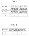
- Figure 5 and Fig. 6 are views illustrating the content of the editing data output by the editing apparatus 50 shown in Fig. 1 to the control system 10.
- the editing data output by the editing apparatus 50 (Fig. 1) to the control system 10 of the data recording and reproducing apparatus 1 is comprised by, for example, as shown in Fig. 5, the file name of the audio and/or video data (stock data) having a part used for the edited data, the reproduction start position data indicating the leading position in the stock data of the part (partial data) which will be contained in the edited data among the stock data, and the reproduction ending position data indicating the last position of the partial data in the stock data.
- the content of the editing data becomes as shown in Fig. 6.
- the control system 10 controls the reproducing system 40 to make it reproduce the data by combining in the order indicated by the editing data the partial data existing in a range from the reproduction start position data to the reproduction ending position (reproduction range data) among the stock data indicated by the file name of the editing data and the record entry, whereby the audio and/or video data having the same content as that of the edited result data determined as the result of the editing by the editor in the editing apparatus 50 can be reproduced.
- the control system 10 makes the reproducing system 40 reproduce the 180th block to 219th block of the hard disc array 30 and next reproduce the 100th block to 119th block, whereby the audio and/or video data having the same content as that of the edited result data is reproduced.
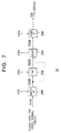
- Figure 7 is a view of the configuration of the recording system 20 shown in Fig. 1.
- the recording system 20 is constitute by an input interface circuit (input IF circuit) 200, an encoder circuit (ENC) 202, a buffer circuit (Buff) 204, and a hard disc interface circuit (HDD IF circuit) 206.
- input IF circuit input interface circuit
- ENC encoder circuit
- Buff buffer circuit
- HDD IF circuit hard disc interface circuit
- the component parts of the recording system 20 operate under control by the control signals C20 1 to C20 4 from the control system 10, compress and code the audio and/or video data of an analog format or digital format input from an external apparatus such as a communication line or a video tape recorder (VTR), and records the compressed and coded data in the hard disc array 30.
- an external apparatus such as a communication line or a video tape recorder (VTR)
- VTR video tape recorder
- the input IF circuit 200 receives the audio and/or video signal of the analog format from the external apparatus, converts this to the audio and/or video data of the digital format, and outputs the same to the encoder circuit 202. Note that, where the audio and/or video data of the digital format is input, the input IF circuit 200 receives the audio and/or video data and outputs this as it is to the encoder circuit 202.
- the encoder circuit 202 compresses and codes the audio and/or video data input from the input IF circuit 200 by for example an MPEG system and outputs the compressed and coded data to the buffer circuit 204. Note that, where the audio and/or video data input from the input IF circuit 200 has been already compressed and coded, as indicated by a dotted line in Fig. 7, the encoder circuit 202 can be omitted.
- the buffer circuit 204 buffers the compressed and coded audio and/or video data and outputs the same to the HDD IF circuit 206. In this way, the buffer circuit 204 adjusts the timing of input/output of the data between the encoder circuit 202 and the HDD IF circuit 206.
- the HDD IF circuit 206 outputs the audio and/or video data (S20) to the hard disc array 30 according to for example an SCSI (Small Computer System Interface) protocol, designates the empty recording regions indicated by the free space list (Fig. 3D, Fig. 4C) input from the control system 10 in the hard disc array 30, and makes it record the audio and/or video data input from the buffer circuit 204 in the designated empty recording regions in order.
- SCSI Small Computer System Interface
- the hard disc array 30 (Fig. 1) is constituted by for example a large number of large capacity hard disc devices, uses the hard discs (not illustrated) possessed by the large number of hard disc devices as a single randomly accessible recording medium having a recording capacity of 400 GB as a whole, records the audio and/or video data input from the buffer circuit 204 of the recording system 20 in the designated recording regions of the recording medium according to the SCSI protocol, reproduces the stock data from the designated recording regions, and outputs the same to the HDD IF circuit 400 (Fig. 8) of the reproducing system 40.
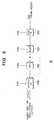
- Figure 8 is a view of the configuration of the reproducing system 40 shown in Fig. 1.
- the reproducing system 40 is constituted by an HDD IF circuit 400, a buffer circuit 402, a decoder circuit (DEC) 406, and an output interface circuit (output IF circuit) 408.
- HDD IF circuit 400 the reproducing system 40 is constituted by an HDD IF circuit 400, a buffer circuit 402, a decoder circuit (DEC) 406, and an output interface circuit (output IF circuit) 408.
- DEC decoder circuit
- output IF circuit output IF circuit
- the component parts of the reproducing system 40 operate under the control of the control system 10 via control signals C40 1 to C40 4 and reproduce the audio and/or video data (stock data) designated by the control system 10 from the hard disc array 30 or part (partial data) of the stock data, expand and decode the same, and output the resultant data to the external apparatus.
- the HDD IF circuit 400 makes the hard disc array 30 reproduce the audio and/or video data from the recording regions designated by the control system 10, receives the audio and/or video data reproduced according to for example the SCSI protocol, and outputs this to the buffer circuit 402.
- the buffer circuit 402 buffers the audio and/or video data input from the HDD IF circuit 400, adjusts the input/output timing of the data, and outputs the resultant data to the decoder circuit 406.
- the decoder circuit 406 expands and decodes the audio and/or video data input from the buffer circuit 402 and outputs the resultant data to the output IF circuit 408. Note that, as indicated by the dotted line in Fig. 8, where noncompressed audio and/or video data is input from the buffer circuit 402, the decoder circuit 404 is unnecessary.
- the output IF circuit 408 converts the audio and/or video data of the digital format input from the decoder circuit 406 to an audio and/or video signal of the analog format and outputs the same to the external apparatus. Note that, where the external apparatus connected to the output IF circuit 408 handles audio and/or video data of the digital format, the output IF circuit 408 does not convert the audio and/or video data to the analog format data, but outputs this as it is to the external apparatus.
- the input IF circuit 200 (Fig. 7) converts the input audio and/or video signal to digital format data.
- the encoder circuit 202 compresses and codes the input audio and/or video data.
- the buffer circuit 204 adjusts the timing of the input/output of the data between the encoder circuit 202 and the HDD IF circuit 206.
- the HDD IF circuit 206 records the audio and/or video data (stock data) in the empty recording regions indicated by the free space list (Fig. 3D, Fig. 4C) input from the control system 10.
- the microprocessor circuit 102 of the control system 10 generates the record entry shown in Figs. 3B and 3C and Fig. 4, updates the free space list shown in Fig. 3D, stores this in the RAM circuit 106 (Fig. 2), and records this in a predetermined recording region of the hard disc array 30.
- the control system 10 controls the reproducing system 40 to make it reproduce the stock data designated by the editing apparatus 50 and returns the record entry of the reproduced stock data to the editing apparatus 50 as the response data.
- the editing apparatus 50 displays the audio and/or video of the stock data sent from the data recording and reproducing apparatus 1 to the editor.
- the editor determines the audio and/or video to be contained in the audio and/or video data for the program while watching and listening to the displayed audio and/or video.
- the editor inputs data indicating the audio and/or video to be adopted to the editing apparatus 50.
- the editing apparatus 50 generates the editing data (Fig. 5) indicating the partial data used in the audio and/or video data (edited data) for the program and the order thereof according to the record entry received from the control system 10 and the data input by the editor and outputs the same to the control system 10.
- the microprocessor circuit 102 (Fig. 2) of the control system 10 stores the received editing data in the RAM circuit 106 and controls the recording system 20 to make it record the editing data in a predetermined recording region of the hard disc array 30.
- the microprocessor circuit 102 (Fig. 2) of the control system 10 calculates the recording regions of the recording medium of the hard disc array 30 in which the partial data contained in the edited data is recorded based on the editing data stored in the RAM circuit 106 and the recording position data (Figs. 3B, 3C and 4B) and outputs the same to the HDD IF circuit 400 (Fig. 8) of the reproducing system 40.
- the HDDIF circuit 400 reproduces the audio and/or video data (partial data) from the recording region of the partial data input from the control system 10 in the order indicated by the editing data.
- the buffer circuit 402 adjusts the timing of the data input/output between the HDD IF circuit 400 and the decoder circuit 406.
- the decoder circuit 406 expands and decodes the input audio and/or video data.
- the output IF circuit 408 converts the audio and/or video data to audio and/or video signal of the analog format and outputs the same to the external apparatus.
- audio and/or video data the same as the result of editing can be reproduced without further recording the edited data comprised by the part (partial data) of the stock data recorded in the hard disc array 30 in an overlapping manner on the stock data. Accordingly, the recording capacity of the hard disc array 30 does not become wasted and editing of audio and/or video data spanning a long period of time by the editing apparatus 50 becomes possible.
- the hard disc array 30 can be replaced by another recording and reproducing apparatus realizing an equivalent recording capacity by using for example a large number of MO disc devices.
- the data recording and reproducing apparatus 1 deal with just one of the video data or the audio data.
- the component parts of the data recording and reproducing apparatus 1 can be replaced by other means having an equivalent function and performance.
- a predetermined effect i.e., the effective utilization of the recording capacity of the hard disc array 30, can be achieved, but since the editing data is recorded in the RAM circuit 106 (Fig. 2) in a form not changed from the state received from the editing apparatus 50 and is converted to data showing the recording regions of the partial data at the time of reproduction, there is a problem of a long processing time. Further, it is cannot be determined which data among the stock data recorded in the hard disc array 30 will be used as the stock data until the content of the editing data is viewed, thus there is a problem in that the data may be deleted irrespective of the fact that it is to be used as the stock data.
- the file management method in the control system 10 is improved.
- a reproduction entry of a linked list format indicating the recording regions of the partial data contained in the same edited data is generated in advance based on the record entry and the editing data, the partial data is reproduced based on this reproduction entry, and further an identification flag (delete enable flag) is added to the record entry in the control system 10 and the reproduction entry.
- This delete enable flag is checked to prevent the stock data from being unintentionally deleted.
- the operation of the recording system 20, hard disc array 30, and the reproducing system 40 of the data recording and reproducing apparatus 1 in the second embodiment and the operation of the recording system 20, the hard disc array 30, and the reproducing system 40 of the data recording and reproducing apparatus 1 in the first embodiment are the same. Only the processing regarding the management of the stock data and partial data of the control system 10 are different.
- Figure 9 is a view corresponding to Fig. 3 in the first embodiment and illustrates the recording region data (first recording region data) of the recording region occupied by the stock data A and B in the recording medium of the hard disc array 30 shown in Fig. 1 and the stock data in the second embodiment.
- Figure 10 is a view corresponding to Fig. 4 in the first embodiment and illustrates the content of the recording region data of the stock data stored in the RAM circuit 106 by the microprocessor circuit 102 shown in Fig. 2 in the second embodiment.
- Figs. 9A, 9D and Figs. 10A, 10C are the same as Figs. 3A, 3D and Figs. 4A, 4C.
- the stock data A and B are recorded in the recording medium of the hard disc array 30, the stock data A is recorded in the 80th block to 129th block and the 230th block to 329th block from the head of the recording medium, the stock data B is recorded in the 170th block to 229th block from the head of the recording medium, and the other recording regions are empty recording regions.
- the microprocessor circuit 102 prepares the recording region data of each of the stock data A and B as the record entry shown in Figs. 9B and 9C in the same way as the control system 10 in the first embodiment and stores link data (file entry) indicating the file name and the first record entry in the RAM circuit 106 as shown in Fig. 10A for each of the stock data A and B.
- an identification flag delete enable flag; ON, OFF
- the value OFF of this delete enable flag indicates that the corresponding audio and/or video data cannot be deleted, and the value ON of the delete enable flag indicates that the corresponding audio and/or video data can not be deleted.
- the microprocessor circuit 102 generates the free space list shown in Fig. 9D and Fig. 10C in the same way as the control system 10 in the first embodiment.
- the free space list is clearly distinguished from the other list in the processing of the microprocessor circuit 102, the free space list is required even if no stock data is recorded in the hard disc array 30 and will not be deleted, therefore the delete enable flag is not added.
- Figure 11 is a view illustrating the reproduction entry generated based on the editing data output by the editing apparatus 50 shown in Fig. 1 to the control system 10 of the data recording and reproducing apparatus 1 and the record entry and the editing data shown in Figs. 9B and 9C in the second embodiment.
- the editing apparatus 50 (Fig. 1) outputs for example the editing data shown in Fig. 11A to the external IF circuit 100 of the control system 10 in the second embodiment in the same way as the first embodiment.
- This editing data indicates that the part (partial data) contained in the range from the 10th block to 50th block of the stock data A and the partial data contained in the range from the 20th block to 50th block of the stock data B and the partial data contained in the range from the 0th block to the 30th block of the stock data B' are contained in the edited data X in this order.
- the microprocessor circuit 102 of the control system 10 stores the link data (file entry) indicating the file name X shown in Fig. 11B and the first reproduction entry in the RAM circuit 106 based on the editing data (Fig. 11A received from the editing apparatus 50 and the record entry (Figs. 9A, 9B). Further, the microprocessor circuit 102 generates the recording region data (reproduction entry) indicating that the partial data contained in the stock data A and B are recorded in the 40 blocks from the 180th block from the head of the recording region of the recording medium of the hard disc array 30, in the 30 blocks from the 100th block, and in the 30 blocks from the 230th block, adds this while making the value of the delete enable flag OFF, and stores this in the RAM circuit 106.
- the microprocessor circuit 102 generating the reproduction entry makes the value of the record entry of the audio and/or video data (stock data) referred to by the reproduction entry ON and records the recording region data in the predetermined recording region of the recording medium of the hard disc array 30.
- the editing data is stored in the RAM circuit 106 as it is and the recording regions of the partial data are calculated at the time of reproduction
- the reproduction entry is generated in the form of a linked list shown in Fig. 11B in advance and stored in the RAM circuit 106, the calculation of the recording regions of the partial data at the time of reproduction becomes unnecessary and audio and/or video data having the same content as that of the edited data can be quickly reproduced.
- the time for processing for calculation of the recording regions of the partial data at the time of reproduction does not particularly become obstruct the reproduction, but the larger the number of the division of the partial data, the longer the calculation processing time and the larger the possibility of obstructing the reproduction. Accordingly, where the editing data of the edited data containing a lot of partial data is input to the control system 10 from the editing apparatus 50, the merit of generating the reproduction entry in advance becomes large.
- the operation of the data recording and reproducing apparatus 1 in the second embodiment will be explained focusing on the generation of the record entry and the reproduction entry.
- the operations of the recording system 20, hard disc array 30, reproducing system 40, and editing apparatus 50 in the second embodiment are as explained referring to the first embodiment, and only the processing of the control system 10 in the second embodiment (concretely, the storage content of the ROM circuit 104) is different from that of the first embodiment.
- Figure 12 is a flowchart showing the processing when the microprocessor circuit 102 of the control system 10 shown in Fig. 2 records the audio and/or video data input from the outside in the hard disc array 30 in the second embodiment.
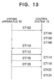
- Figure 13 is a signal sequence diagram between the editing apparatus 50 and the control system 10 when the microprocessor circuit 102 of the control system 10 shown in Fig. 2 records the audio and/or video data input from the outside in the hard disc array 30 in the second embodiment.
- the editing apparatus 50 (Fig. 1) outputs a command (OPEN_REC command) containing predetermined data such as the file name A and data length (60 blocks) for making the control system 10 (Fig. 2) prepare the record entry of the audio and/or video data etc. to the control system 10.
- the control system 10 receives this OPEN_REC command.
- step 104 the microprocessor circuit 102 of the control system 10 generates the file entry (Figs. 9B, 9C and 10B) and the other data (Fig. 10A), stores them in the RAM circuit 106, and further records them in a predetermined recording region of the recording medium of the hard disc array 30.
- step 106 the microprocessor circuit 102 of the control system 10 analyzes the free space list stored in the RAM circuit 106 and secures the regions for the recording.
- step 108 the microprocessor circuit 102 of the control system 10 generates the record entry (Fig. 9B) based on the data such as the file name contained in the OPEN_REC command, records this in the RAM circuit 106, and records this in the hard disc array 30.
- step 110 the microprocessor circuit 102 of the control system 10 generates the file handle (Fig. 19A), stores this in the RAM circuit 106, and records this in the hard disc array 30.
- the editing apparatus 50 outputs the command (REC command) for starting the recording of the audio and/or video data A to the control system 10.
- the microprocessor circuit 102 of the control system 10 receives this REC command.
- step 114 the microprocessor circuit 102 of the control system 10 receiving the REC command controls the recording system 20 to make it record the audio and/or video data input from the external apparatus in the hard disc array 30.
- step 116 the editing apparatus 50 outputs the command for ending the recording of the audio and/or video data A (STOP command) to the control system 10.
- the control system 10 receives this STOP command.
- step 118 the microprocessor circuit 102 of the control system 10 receiving the STOP command controls the recording system 20 to stop the recording of the audio and/or video data A.
- the editing apparatus 50 outputs the command for revising (updating) the record entry and the free space list (CLOSE command) to the control system 10.
- the microprocessor circuit 102 of the control system 10 receives this CLOSE command.
- step 122 the microprocessor circuit 102 of the control system 10 updates the record entry and the free space list.
- Figure 14 is a flowchart showing the processing when the microprocessor circuit 102 of the control system 10 shown in Fig. 2 reproduces the audio and/or video data in the second embodiment.
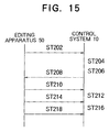
- Figure 15 is a signal sequence diagram of the processing when the microprocessor circuit 102 of the control system 10 shown in Fig. 2 reproduces the audio and/or video data.
- the editing apparatus 50 outputs the command for preparing the reproduction of the audio and/or video data containing the data such as the file name A (OPEN_PLAY command) to the control system 10.
- the microprocessor circuit 102 of the control system 10 receives this OPEN_PLAY command.
- step 204 (ST204) and step 206 (ST206) the microprocessor circuit 102 of the control system 10 searches for the file entry recorded in the RAM circuit 106 (Fig. 2) and finds the record entry of the audio and/or video data A based on the result of the search.
- control system 10 At step 208 (ST208), the control system 10 generates the file handle and records this in the RAM circuit 106.
- the editing apparatus 50 outputs the command for starting the reproduction of the audio and/or video data A (PLAY command) to the control system 10.
- the microprocessor circuit 102 of the control system 10 receives this PLAY command.
- the microprocessor circuit 102 of the control system 10 controls the reproducing system 40 to reproduce the audio and/or video data A recorded in the hard disc array 30 and output the same to the editing apparatus 50 and further outputs the record entry of the audio and/or video data A to the editing apparatus 50.
- step 214 the editing apparatus 50 outputs the command (STOP command) for stopping the reproduction of the audio and/or video data A to the control system 10.
- the control system 10 receives this STOP command.
- control system 10 controls the recording system 20 and makes it stop the reproduction of the audio and/or video data A.
- the editing apparatus 50 outputs the command for revising (updating) the record entry and the free space list (CLOSE command) to the control system 10.
- the control system 10 receives this CLOSE command and closes the file of the audio and/or video data A which has been reproduced.
- Figure 16 is a flowchart showing the processing when the microprocessor circuit 102 of the control system 10 shown in Fig. 2 reproduces the audio and/or video data based on the reproduction entry (Fig. 11B) in the second embodiment.
- the editing apparatus 50 outputs the command (VFL_DOWNLOAD command) containing the editing data for making the control system 10 receive the editing data to the control system 10.
- the control system 10 receives this VFL_DOWNLOAD command.
- step 404 (ST404) and step 406 (ST406) the control system 10 analyzes the received editing data and the record entry (Figs. 9B and 9C) of the audio and/or video data A and B, generates the reproduction entry of the edited data X and the file entry (Fig. 11B) thereof, stores them in the RAM circuit 106, and further records them in a predetermined recording region of the hard disc array 30.
- the editing apparatus 50 outputs to the control system 10 the command for combining the partial data based on the reproduction entry and making the control system 10 perform the preparations for reproducing the audio and/or video data having the same content as that of the edited data (VFL_OPEN command).
- the control system 10 receives this VFL_OPEN command.
- step 410 the microprocessor circuit 102 of the control system 10 searches for the reproduction entry of the edited data X stored in the RAM circuit 106. Note that, at this time, the reproduction entry of the edited data X is treated exactly the same as the audio and/or video data A and B.
- step 412 the microprocessor circuit 102 of the control system 10 generates the file handle.
- the editing apparatus 50 outputs the PLAY command to the control system 10.
- the control system 10 receives this PLAY command.
- step 416 the microprocessor circuit 102 of the control system 10 controls the reproducing system 40 to make it reproduce the partial data from the hard disc array 30 based on the reproduction entry.
- the editing apparatus 50 outputs the STOP command to the control system 10.
- the control system 10 receives this STOP command.
- step 420 the microprocessor circuit 102 of the control system 10 controls the reproducing system 40 and makes it stop the reproduction of the partial data.
- the editing apparatus 50 outputs the CLOSE command to the control system 10.
- the control system 10 receives this CLOSE command.
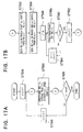
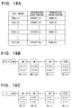
- Figure 17 is a flowchart showing the processing for generating the reproduction entry from the editing data by the microprocessor circuit 102 of the control system 10 (Fig. 2) in the second embodiment.
- Figure 18 is a view illustrating the editing data, the record entry, and the reproduction entry.
- the microprocessor circuit 102 brings the values of the variables n and j to 1.
- the variable n is used for the search of the file name data (Fig. 18B) of the record entry of the stock data
- the variable j is used for the search of the partial data contained in the reproduction entry (Fig. 18C).
- step 550 the reproduction entry is generated from the file name data (FILE(n)) of the editing data (Fig. 18A), the reproduction start position data (START(n)), and the reproduction ending position data (END(n)).
- FILE(n) file name data
- ST562 the reproduction start position data
- END(n) reproduction ending position data
- the microprocessor circuit 102 of the control system 10 searches for the record entry (RE(n)) of the stock data containing the reproduction start position data (START(n)).
- the microprocessor circuit 102 of the control system 10 searches for the record entry (RE(n)) of the stock data containing the reproduction ending position data (END(n)).
- step 556 the microprocessor circuit 102 of the control system 10 brings the variable i to the numerical value "is". Note that, the variable i is used for the search of the data contained in the record entry.
- step 558 the microprocessor circuit 102 of the control system 10 generates the reproduction entry (RE(j)) of the edited data X.
- step 560 the microprocessor circuit 102 of the control system 10 decides whether or not the value of the variable i is "ie".
- the numerical value "ie” indicates the number of the reproduction entries (RE(j)). Where the value of the variable i is the numerical value "ie”, the operational routine proceeds to the processing of ST562, while where it is not the numerical value "ie", the operational routine proceeds to the processing of ST564.
- step 562 the microprocessor circuit 102 of the control system 10 adds the numerical value 1 to the variable j (increments) and proceeds to the processing of ST506.
- step 564 the microprocessor circuit 102 of the control system 10 increments the variables i and j and proceeds to the processing of ST558.
- step 506 the microprocessor circuit 102 of the control system 10 decides whether or not the value of the variable n is the numerical value "end". Note that, the numerical value "end” indicates the number of the stock data. Where the variable n is the numerical value "end”, the processing is ended, while where it is not the numerical value "end”, the operational routine proceeds to the processing of ST508.
- step 508 the microprocessor circuit 102 of the control system 10 increments the variable n and proceeds to the processing of ST550 (ST552).
- the microprocessor circuit 102 of the control system 10 receiving the command for deleting the audio and/or video data from the editing apparatus 50 searches for the record entry, deletes only the data in which the value of the delete enable flag is ON, and adds the recording region of the hard disc array 30 indicated by the deleted record entry to the free space list.
- the microprocessor circuit 102 does not delete a record entry in which the value of the delete enable flag is OFF.
- the microprocessor circuit 102 of the control system 10 receiving the command for deleting the reproduction entry from the editing apparatus 50 searches for the reproduction entry, confirms that the value of the delete enable flag is ON, and deletes this.
- the value of the delete enable flag of the reproduction entry is ON as mentioned above, therefore the stock data (partial data) referred to by the reproduction entry is not usually deleted by the delete command from the editing apparatus 50.
- the audio and/or video data having the same content as that of the edited data can be reproduced without a necessity of recording the edited data in the hard disc array 30.
- the reproduction entry is generated in advance and the reproduction is performed based on this reproduction entry, therefore the processing time for calculation of the recording regions of the partial data shown in the first embodiment becomes unnecessary. Accordingly, the processing time for calculation of the recording regions will not obstruct the reproduction.
- the generation of the reproduction entry shown in the second embodiment is performed just by rewriting the storage content of the RAM circuit 106, thus it is not necessary to make any change to the hardware of the data recording and reproducing apparatus 1 shown in the first embodiment.
- the data recording and reproducing apparatus 1 not only can generate a reproduction entry from two series of stock data, but also can generate a reproduction entry for reproducing the audio and/or video data having the same content as that of the edited data by combining partial data (Fig. 19B) of three or more stock data (Fig. 19A).
- the algorithm of the control system 10 shown in the second embodiment and the signal sequence between the editing apparatus 50 and the control system are examples. So far as the same function and performance can be realized, other algorithms and signal sequences can be adopted.
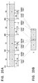
- Figure 20 is a view illustrating the audio and/or video data (edited data) generated as a result of the editing of the stock data A to D.
- the recording capacity of one block of the recording medium of the hard disc array 30 is for example one megabyte (MB).
- Figure 21 is a view of the record entry of the stock data A to D (Fig. 20) and the reproduction entry of the edited data generated based on the editing data which the control system 10 (Fig. 1) shown in the second embodiment received from the editing apparatus 50.
- the editing apparatus 50 respectively edits the partial data having the data lengths of 40 blocks, 5 blocks, 40 blocks, and 5 blocks contained in the stock data A to D shown in Fig. 20A to obtain the edited data shown in Fig. 20B
- the editing data shown in Fig. 21B is input to the control system 10 of the data recording and reproducing apparatus 1 from the editing apparatus 50.
- the data length of the partial data (partial data B and D) of the stock data B and D has become as short as 5 blocks.
- the last part of each of the partial data A and C and the starting part of each of the partial data B and D are recorded in separate recording regions on the recording medium of the hard disc array 30, therefore access to distant recording regions of the recording medium of the hard disc array 30 and a wait for rotation become necessary at the end of reproduction of the partial data B and D.
- each of the partial data B and D has a small data length such as 5 MB, so there is a possibility that the buffer circuit 402 (Fig. 2) of the reproducing system 40 will suffer from an underflow within the time required for the access and wait for rotation. When underflow occurs in the buffer circuit 402, continuous reproduction becomes impossible.
- the data recording and reproducing apparatus 1 in the third embodiment is aimed at the solution of such a problem.
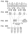
- Figure 22 is a view of the processing of the control system 10 (Fig. 2) of the data recording and reproducing apparatus 1 in the third embodiment. Note that, Fig. 22A is the same as Fig. 20A.
- the control system 10 in the third embodiment analyzes the editing data (Fig. 21B) received from the editing apparatus 50, records short partial data and this short partial data in the predetermined recording region of the recording medium of the hard disc array 30 in advance, obtains a data length not causing the underflow in the buffer circuit 402, and avoids the above inconvenience.
- control system 10 recording system 20, hard disc array 30, and the reproducing system 40 of the data recording and reproducing apparatus 1 in the third embodiment
- the operation of the recording system 20, hard disc array 30, and the reproducing system 40 of the data recording and reproducing apparatus 1 in the second embodiment and the processing other than the management of the stock data and the partial data of the control system 10 are the same.
- control system 10 in the third embodiment will be explained in brief by a concrete example.
- the 110th block to 149th block (data length: 40 blocks)
- the 220th block to 224th block (data length: 5 blocks)
- the 330th block to 369th block (data length: 40 blocks)
- the 420th block to 424th block (data length: 5 blocks) are contained in the edited data as the partial data A to D as shown in Fig. 20B.
- the control system 10 in the third embodiment controls the control system 20, places the partial data a and c in front of the short partial data B and D as shown in Fig. 22C to obtain the partial data ab and cd having the data length of 10 blocks, and records them in advance in a predetermined recording region (for example the 1000th block to 2000th block; compile recording region) of the recording medium of the hard disc array 30.
- a predetermined recording region for example the 1000th block to 2000th block; compile recording region
- the partial data A', ab, C', and cd for the partial data A', ab, C', and cd, it generates the same reproduction entry as that of the second embodiment and stores this in the RAM circuit 106.
- the audio and/or video data having the same content as that of the edited data (Fig. 20B) is reproduced, based on the reproduction entry shown in Fig. 22D, the partial data A', ab, C', and cd are reproduced from the hard disc array 30, whereby, other than the effect such as quick reproduction of the data recording and reproducing apparatus 1 shown in the second embodiment, the effect of guaranteeing the continuous reproduction can be obtained.
- the value of the delete enable flag of the partial data recorded in the compile recording region is made ON and the value of the delete enable flag of the other partial data is made OFF.
- the reason why the value of the delete enable flag is determined in this way is that, even if the data recorded in the compile recording region is deleted, the original stock data will be recorded in the hard disc array 30, so will not be lost.
- compile processing The processing for recording the above explained short partial data in the compile recording region in advance together with part or all of the partial data immediately before the current data will be referred to as compile processing in the third embodiment.
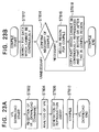
- Figure 23 is a flowchart showing the content of the compile processing performed by the control system 10 of the data recording and reproducing apparatus 1 in the third embodiment.
- Figure 24 is a flowchart showing the content of the compile processing performed by the control system 10 of the data recording and reproducing apparatus 1 in the third embodiment in further detail.
- the editing apparatus 50 outputs to the control system 10 the command containing the editing data for making the control system 10 receive the editing data (VFL_DOWNLOAD command).
- the control system 10 receives this VFL_DOWNLOAD command.
- the microprocessor circuit 102 of the control system 10 analyzes the received editing data and record entry of the audio and/or video data A and B (Figs. 9B and 9C), generates the reproduction entry (Fig. 21C) of the edited data X and the file entry (Fig. 11B) thereof, stores them in the RAM circuit 106, and further records them in the predetermined recording region of the hard disc array 30.
- step 610 the microprocessor circuit 102 of the control system 10 performs the compile processing shown in Figs. 22B and 22C.
- the content of the compile processing is as shown in ST612 to ST618 shown in Fig. 23B.
- step 612 (ST612) and step 614 (ST614) (ST702 to ST708 in Fig. 24), the microprocessor circuit 102 of the control system 10 searches for the reproduction entry and detects the partial data with a data length not more than the predetermined value T (10 blocks in the example shown in Fig. 22), that is, the partial data which cannot be continuously reproduced. Where there is only one series of partial data having a data length not more than the predetermined value T and the compile processing is necessary, the operational routine proceeds to the processing of ST616, while where it is not necessary, the processing is ended.
- T data length not more than the predetermined value
- step 616 (ST616) (ST714 in Fig. 24), the microprocessor circuit 102 of the control system 10 secures the recording region of the recording medium of the hard disc array 30 necessary for the compile processing (for the compile recording region (Fig. 22C)). Note that, where the compile recording region is provided in the recording medium of the hard disc array 30 in a fixed manner, the processing of ST616 is unnecessary. Further, where the compile recording region is insufficient, it is necessary to further enlarge the compile recording region.
- the microprocessor circuit 102 of the control system 10 continuously records part of the partial data before and after the partial data for which the continuous reproduction is impossible in the compile recording region as shown in Fig. 22C and changes the data length to above T. Further, the microprocessor circuit 102 of the control system 10 prepares the reproduction entry (Fig. 22D anew based on the partial data after the compilation, stores this in the RAM circuit 106, and records this in the predetermined recording region of the recording medium of the hard disc array 30.
- microprocessor circuit 102 of the control system 10 manages the empty recording regions using the free space list (Fig. 9D) and the processing for securing the recording region also for the compile recording region.
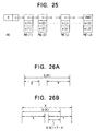
- variable Z in ST740 in Fig. 24 indicates the data length of the data removed from the partial data immediately before the short partial data for obtaining the data having the data length T or more in addition to the short partial data (Fig. 20B) as shown in Fig. 26A.
- the numerical value s(k)-T-X at ST756 in Fig. 24 indicates the data length of the data removed from the partial data immediately after the short partial data so as to obtain the data having the data length T or more in addition to the short partial data (Fig. 20B) as shown in Fig. 26B.
- the data recording and reproducing apparatus 1 shown in the third embodiment can continuously reproduce the audio and/or video data the same as the edited data quickly and in addition reliably similar to the data recording and reproducing apparatus 1 shown in the second embodiment.
- the data recording and reproducing apparatus 1 shown in the third embodiment even in a case where the audio and/or video data having the same content as that of the edited data is reproduced by combining partial data having a variety of lengths, the continuity of the reproduced audio and/or video data is not degraded.
- data recording and reproducing apparatus 1 shown in the third embodiment may be similarly modified as with the data recording and reproducing apparatuses 1 shown in the first embodiment and the second embodiment.
- audio and/or video data recording and reproducing apparatus and audio and/or video data recording and reproducing method of the present invention it is possible to record a plurality of series of audio and/or video data to be edited in a randomly accessible recording medium such as a hard disc and MO disc, reproduce any audio and/or video data in accordance with the request of an outside apparatus such as an editing apparatus and provide the same.
- a randomly accessible recording medium such as a hard disc and MO disc
- audio and/or video data recording and reproducing apparatus and audio and/or video data recording and reproducing method are suitable for editing of audio and/or video data over a long period.
- audio and/or video data recording and reproducing apparatus and audio and/or video data recording and reproducing method audio and/or video data having exactly the same content as that of the audio and/or video data of the result of editing (edited data) can be reproduced without recording audio and/or video data having the same content in the recording medium in an overlapping manner.
Abstract
Description
- The present invention relates to information data recording and reproducing apparatus and methods, suitable for recording information data such as audio and/or video data in a randomly accessible recording medium such as a hard disc, and for reproducing the recorded data.
- In recent years, a hard disc array comprising a large number of large capacity hard disc devices connected together, having a combined recording capacity of several tens to several hundreds of gigabytes (GB), and able to perform random access has been put into practical use.
- This hard disc array is suited for the recording of data having a very large amount of data such as audio data and video data or one of the same (audio and/or video data) and is particularly suitable for use as the recording and reproducing apparatus for an editing apparatus due to the characteristic that it can reproduce any audio and/or video data with a short access time.
- However, when the edited audio and/or video data is recorded again in the hard disc array in which the audio and/or video data covered by the editing (stock data) is recorded, the audio and/or video data having the same content is recorded in an overlapping manner, the recording capacity of the hard disc array becomes wasted, and there is a possibility that it will not be possible to perform editing of audio and/or video data spanning a long period of time.
- According to a first aspect of the present invention there is provided an information data recording and reproducing apparatus comprising: an information data recording means for recording a plurality of series of information data in a randomly accessible recording medium, a first recording region generating means for generating first recording region data showing the recording regions occupied by the plurality of series of information data in the recording medium, and a combination reproducing means for reproducing by combination as partial data part or all of the information data of the stock data recorded in the recording medium. The combination reproducing means has a second recording region data generating means for generating second recording region data showing the recording regions occupied by the partial data to be reproduced by combination in the recording medium based on the first recording region data of the stock data, and a partial data reproducing means for reproducing the partial data from the recording medium based on the generated second recording region data.
- Preferably, the first recording region data generating means generates a first recording region list showing at least the recording regions occupied by the plurality of series of information data in the recording medium in the form of a linked list showing mutual linkage and includes this in the first recording region data, the second recording region data generating means of the combination reproducing means generates a second recording region list showing at least the recording regions occupied by the partial data to be reproduced by combination in the recording medium in the form of the linked list based on order data showing the order for reproducing the partial data, reproduction range data showing the range occupied by the partial data in the stock data, and the first recording region data of the stock data and includes this in the second recording region data, and the partial data reproducing means reproduces the partial data from the recording regions of the recording medium shown by the second recording region list.
- Preferably, the reproduction range data showing the range occupied by the partial data in the stock data contains a reproduction start position and a reproduction ending position of the partial data in the stock data or one of the same.
- Preferably, the first recording region list generated by the first recording region data generating means and the second recording region list generated by the second recording region data generating means further contain identification flags and adopt mutually the same structure of data, the first recording region data generating means sets the identification flag of the first recording region list to a first value, the second recording region data generating means of the combination reproducing means sets the identification flag of the second recording region list to a second value, and provision is further made of a recording region releasing means for releasing the recording regions of the recording medium shown by the first recording region list and deleting the first recording region list only in a case where the value of the identification data is the first value when receiving a request for releasing the recording regions of the recording medium shown by the first recording region list and the second recording region list.
- Specifically, the plurality of series of information data may be a plurality of audio and/or video data.
- According to a second aspect of the present invention there is provided an information data recording and reproducing method comprising steps of: recording a plurality of series of information data in a randomly accessible recording medium, generating a recording region list showing the recording regions occupied by the partial data to be reproduced by combination in the recording medium in the form of a linked list when reproducing by combination as partial data part or all of the information data of the stock data recorded in the recording medium, and reproducing the partial data from the recording regions of the recording medium shown by the generated recording region list.
- According to a third aspect of the present invention there is provided an information recording and reproducing apparatus, comprising: a first information data recording means for recording a plurality of series of information data in a randomly accessible recording medium, a first recording region generating means for generating a first recording region data indicating the recording regions occupied by the plurality of series of information data in the recording medium a combination reproducing means for reproducing data by combining as partial data part or all of the information data serving as the stock data recorded in the recording medium, and a second information data recording means for continuously recording short partial data having a data length not more than a predetermined data length and a predetermined part of the partial data reproduced before and after the short partial data in a predetermined recording region of the recording medium where the data length of the partial data is not more than the predetermined data length, the combination reproducing means has a second recording region data generating means for generating second recording region data indicating the recording regions occupied in the recording medium by the partial data reproduced by combination and the predetermined part of the unit data and the short partial data recorded in the predetermined recording region of the recording medium based on the first recording region data of the stock data and a partial data reproducing means for reproducing the partial data from the recording medium based on the generated second recording region data.
- Specifically, the plurality of series of information data may be a plurality of series of audio and/or video data.
- According to a fourth aspect of the present invention there is provided an information data recording and reproducing method comprising the steps of: recording a plurality of series of information data in a randomly accessible recording medium, continuously recording short partial data having a data length not more than a predetermined data length and a predetermined part of the partial data reproduced before and after the short partial data in a predetermined recording region of the recording medium where the data length of the partial data is not more than the predetermined data length when reproducing data by combining as partial data part or all of the information data serving as the stock data recorded in the recording medium, generating a recording region list for indicating the recording regions occupied by the partial data reproduced in combination and the predetermined part of the partial data recorded in the predetermined recording region of the recording medium and the short partial data in the recording medium by a linked list format, and reproducing the partial data from the recording regions of the recording medium indicated by the generated recording region list.
- Preferred embodiments of the present invention provide information data recording and reproducing apparatus and an information data recording and reproducing method capable of recording a plurality of series of information data to be edited in a randomly accessible recording medium such as a hard disc or magneto-optical disc (MO disc), reproducing any information data in accordance with a request of an external apparatus such as an editing apparatus, and providing the same.
- The preferred information data recording and reproducing apparatus and method are suited for editing of information data spanning a long period of time.
- Information data having exactly the same content as that of the information data resulting from editing (edited data) can be reproduced without recording all of the information data having the same content in the recording medium in an overlapping manner.
- The invention will now be described by way of example with reference to the accompanying drawings, throughout which like parts are referred to by like references, and in which:
- Fig. 1 is a view of the configuration of a data recording and reproducing apparatus according to a first embodiment of the present invention;
- Fig. 2 is a view of the configuration of a control system shown in Fig. 1;
- Figs. 3A to 3D are views illustrating recording regions occupied by the audio and/or video data A and B in a recording medium of a hard disc array shown in Fig. 1 and recording region data (first recording region data) in the first embodiment;
- Figs. 4A to 4C are views illustrating the contents of the recording region data stored in the RAM circuit by the microprocessor circuit shown in Fig. 2 in the first embodiment;
- Fig. 5 is a view illustrating the contents of the editing data output by the editing apparatus shown in Fig. 1 to the control system in the first embodiment;
- Fig. 6 is a view illustrating the contents of the editing data output by the editing apparatus shown in Fig. 1 to the control system in the first embodiment;
- Fig. 7 is a view of the configuration of the recording system shown in Fig. 1;
- Fig. 8 is a view of the configuration of the reproducing system shown in Fig. 1;
- Figs. 9A to 9D are views illustrating a recording region occupied by stock data A and B in the recording medium of the hard disc array shown in Fig. 1 and the recording region data (first recording region data) in a second embodiment;
- Figs. 10A to 10C are views illustrating the contents of the recording region data of the stock data stored in the RAM circuit by the microprocessor circuit shown in Fig. 2 in the second embodiment;
- Fig. 11A and Fig. 11B are views illustrating the editing data output by the editing apparatus shown in Fig. 1 to the control system of the data recording and reproducing apparatus and the reproduction entry generated based on the record entry and editing data shown in Fig. 9 in the second embodiment;
- Fig. 12 is a flowchart showing the processing when the microprocessor circuit of the control system shown in Fig. 2 records the audio and/or video data input from the outside in the hard disc array in the second embodiment;
- Fig. 13 is a signal sequence diagram between the editing apparatus and the control system when the microprocessor circuit of the control system shown in Fig. 2 records the audio and/or video data input from the outside in the hard disc array in the second embodiment;
- Fig. 14 is a flowchart showing the processing when the microprocessor circuit of the control system shown in Fig. 2 reproduces the audio and/or video data in the second embodiment;
- Fig. 15 is a signal sequence diagram of the processing when the microprocessor circuit of the control system shown in Fig. 2 reproduces the audio and/or video data in the second embodiment;
- Fig. 16 is a flowchart showing the processing when the microprocessor circuit of the control system shown in Fig. 2 reproduces the audio and/or video data based on the reproduction entry (Fig. 11B) in the second embodiment;
- Fig. 17A and Fig. 17B are flowcharts showing the processing for generating the reproduction entry from the editing data by the microprocessor circuit of the control system shown in Fig. 2 in the second embodiment;
- Figs. 18A to 18C are views illustrating the editing data, record entry, and the reproduction entry;
- Fig. 19A and Fig. 19B are views showing the processing for reproducing the audio and/or video data having the same content as that of the edited data by combining the partial data of three or more series of stock data by the data recording and reproducing apparatus shown in Fig. 1;
- Fig. 20A and Fig. 20B are views illustrating the audio and/or video data generated as the result of the editing with respect to the stock data A to D;
- Figs. 21A to 21C are views showing the record entry of the stock data A to D generated by the control system shown in the second embodiment based on the editing data received from the editing apparatus and the reproduction entry of the edited data;
- Figs. 22A to 22D are views showing the processing content of the control system (Fig. 2) of the data recording and reproducing apparatus in a third embodiment;
- Fig. 23 is a flowchart showing the content of the compile processing performed by the control system of the data recording and reproducing apparatus in the third embodiment;
- Fig. 24 is a flowchart showing the content of the compile processing performed by the control system of the data recording and reproducing apparatus in the third embodiment in further detail;
- Fig. 25 is a view for defining the data b(k) and s(j) in the reproduction entry R(k) in the flowchart shown in Fig. 24; and
- Fig. 26A and Fig. 26B are views for defining the variable Z in the processing at ST740 shown in Fig. 24 and the numerical value s(k)-T-X in the processing of ST756 shown in Fig. 24.
- Figure 1 is a view of the configuration of a data recording and reproducing
apparatus 1 according to the first embodiment of the present invention. - As shown in Fig. 1, the data recording and reproducing
apparatus 1 is configured by acontrol system 10, arecording system 20, a hard disc array (HDD) 30, and areproducing system 40. - The data recording and reproducing
apparatus 1 records a plurality of series of audio data and video data or one of the same (audio and/or video data), and provides the audio and/or video data for editing to anediting apparatus 50 in accordance with a request from theediting apparatus 50 connected to the data recording and reproducingapparatus 1. Further, the data recording and reproducingapparatus 1 receives data (editing data) indicating which part of the stock data is to be used in the audio and/or video data obtained as the result of the editing (edited data) from theediting apparatus 50 and reproduces the audio and/or video data having the same content as that of the edited data based on this editing data. - Figure 2 is a view of the configuration of the
control system 10 shown in Fig. 1. - As shown in Fig. 1, the
control system 10 is constituted by an external interface circuit (external IF circuit) 100, a microprocessor circuit (CPU) 102, aROM circuit 104, aRAM circuit 106, abus 108, and control interface circuits (control IF circuits) 110 and 112. - The
control system 10 constitutes the controlling computer by these component parts, controls the component parts of the data recording and reproducingapparatus 1 based on the editing data input from the editing apparatus 50 (Fig. 1) and manages the recording regions of the series of audio and/or video data recorded in thehard disc array 30. - In the
control system 10, the external IFcircuit 100 receives the editing data input from theediting apparatus 50 and outputs this to themicroprocessor circuit 102. Further, the external IFcircuit 100 receives the response data returned to theediting apparatus 50 by themicroprocessor circuit 102 via the reproducingsystem 40 and outputs this to theediting apparatus 50. - The
microprocessor circuit 102 is constituted by for example a general purpose microprocessor or an RISC (Reduced Instruction Set Computer) microprocessor and the peripheral circuits thereof. Themicroprocessor circuit 102 executes the programs stored in theROM circuit 104 by using theRAM circuit 106 and transmits and receives the editing data and the response data with theediting apparatus 50. - Further, the
microprocessor circuit 102 controls the parts of the data recording and reproducingapparatus 1 via the control IFcircuits hard disc array 30 record the audio and/or video data in accordance with a request from theediting apparatus 50 or other external apparatuses, and provides the recorded audio and/or video data to theediting apparatus 50 and other external apparatuses. Further, themicroprocessor circuit 102 generates recording region data indicating the recording regions occupied by the series of audio and/or video data recorded in thehard disc array 30 in the recording medium (hard disc; not illustrated) of the harddisc array device 30. Further, themicroprocessor circuit 102 generates recording region data of the partial data indicating the recording regions occupied by the parts (partial data) of the audio and/or video data contained in the edited data (stock data) in the recording medium of thehard disc array 30. Further, themicroprocessor circuit 102 stores the generated recording region data in theRAM circuit 106 and records this via therecording system 20 in thehard disc array 30. - The contents of the recording region data generated by the
microprocessor circuit 102 will be explained by a concrete example. - Figures 3A to 3C are views illustrating the recording regions occupied by the audio and/or video data A and B in the recording medium of the hard
disc array device 30 shown in Fig. 1 and the recording region data (first recording region data) in the first embodiment. - Figures 4A to 4C are views illustrating the content of the recording region data stored by the
microprocessor circuit 102 shown in Fig. 2 in theRAM circuit 106 in the first embodiment. - For example, as shown in Fig. 3A, the audio and/or video data A and B are recorded in the recording medium of the hard
disc array device 30. The audio and/or video data B is recorded from the 80th block to 129th block from the head of the recording medium and from the 230th block to 329th block (one block is for example one gigabyte (GB)), while the audio and/or video data A is recorded from the 170th block to 229th block from the head of the recording medium. The other recording regions are empty recording regions. - A situation where the audio and/or video data A and B are recorded as shown in Fig. 3A may occur in a case where, for example, when the audio and/or video data is recorded, the 170th block and subsequent blocks of the recording medium exist as the empty recording region nearest the head of the recording region, all of the audio and/or video data A is recorded in the 170th block to 229th block, and thereafter the audio and/or video data recorded in the 80th block to 129th block are deleted, this recording region is released and becomes an empty recording region, the part on the head side of the audio and/or video data B is recorded in this part, and the part on the rear side is recorded in the 230th block and subsequent blocks.
- In this way, there is a case where one series of audio and/or video data will be divided and recorded in a plurality of recording regions, so the
microprocessor circuit 102 prepares the recording region data of each of the audio and/or video data A and B as a list (record entry) of the linked list format shown in Figs. 3B and 3C. Further, themicroprocessor circuit 102 stores the link data (file entry) indicating the file name and the first record entry in theRAM circuit 106 as shown in Fig. 4A for each of the audio and/or video data A and B. Each of the record entries is comprised by, as shown in Fig. 4B, link data indicating the next record entry, head position data indicating the head position of the recording region, and the recording length data indicating the length of the recording region. Note that, where the link data is the end value (END), the next record entry does not exist, and the last part of the audio and/or video data is recorded in the recording region indicated by that record entry. - Further, the
microprocessor circuit 102 generates empty recording region data indicating the empty recording regions (free space) of thehard disc array 30 as a list (free space list) of a linked list format as shown in Fig. 3D. The free space list is comprised by, as shown in Fig. 4C, link data of the next empty recording region, head position data indicating the head position of the empty recording region, and recording length data indicating the length of the empty recording region. - Further, the
microprocessor circuit 102 controls the reproducingsystem 40 at the startup of the data recording and reproducingapparatus 1 to make it reproduce the recording position data from the predetermined recording region of the harddisc array device 30 and generate the above data based on the reproduced recording position data and the data regarding the file name and the data length of the audio and/or video data received from theediting apparatus 50 and other external apparatuses. - Figure 5 and Fig. 6 are views illustrating the content of the editing data output by the
editing apparatus 50 shown in Fig. 1 to thecontrol system 10. - The editing data output by the editing apparatus 50 (Fig. 1) to the
control system 10 of the data recording and reproducingapparatus 1 is comprised by, for example, as shown in Fig. 5, the file name of the audio and/or video data (stock data) having a part used for the edited data, the reproduction start position data indicating the leading position in the stock data of the part (partial data) which will be contained in the edited data among the stock data, and the reproduction ending position data indicating the last position of the partial data in the stock data. - For example, where the 10th block to 50th block from the head of the audio and/or video data (stock data) A is used as the partial data and the 20th block to 40th block from the head of the stock data B is used as the partial data, the content of the editing data becomes as shown in Fig. 6.
- The
control system 10 controls the reproducingsystem 40 to make it reproduce the data by combining in the order indicated by the editing data the partial data existing in a range from the reproduction start position data to the reproduction ending position (reproduction range data) among the stock data indicated by the file name of the editing data and the record entry, whereby the audio and/or video data having the same content as that of the edited result data determined as the result of the editing by the editor in theediting apparatus 50 can be reproduced. When taking as an example a case shown in Fig. 3 and Fig. 6, thecontrol system 10 makes the reproducingsystem 40 reproduce the 180th block to 219th block of thehard disc array 30 and next reproduce the 100th block to 119th block, whereby the audio and/or video data having the same content as that of the edited result data is reproduced. - Figure 7 is a view of the configuration of the
recording system 20 shown in Fig. 1. - As shown in Fig. 7, the
recording system 20 is constitute by an input interface circuit (input IF circuit) 200, an encoder circuit (ENC) 202, a buffer circuit (Buff) 204, and a hard disc interface circuit (HDD IF circuit) 206. - The component parts of the
recording system 20 operate under control by the control signals C201 to C204 from thecontrol system 10, compress and code the audio and/or video data of an analog format or digital format input from an external apparatus such as a communication line or a video tape recorder (VTR), and records the compressed and coded data in thehard disc array 30. - In the
recording system 20, the input IFcircuit 200 receives the audio and/or video signal of the analog format from the external apparatus, converts this to the audio and/or video data of the digital format, and outputs the same to the encoder circuit 202. Note that, where the audio and/or video data of the digital format is input, the input IFcircuit 200 receives the audio and/or video data and outputs this as it is to the encoder circuit 202. - The encoder circuit 202 compresses and codes the audio and/or video data input from the input IF
circuit 200 by for example an MPEG system and outputs the compressed and coded data to thebuffer circuit 204. Note that, where the audio and/or video data input from the input IFcircuit 200 has been already compressed and coded, as indicated by a dotted line in Fig. 7, the encoder circuit 202 can be omitted. - The
buffer circuit 204 buffers the compressed and coded audio and/or video data and outputs the same to the HDD IFcircuit 206. In this way, thebuffer circuit 204 adjusts the timing of input/output of the data between the encoder circuit 202 and the HDD IFcircuit 206. - The HDD IF
circuit 206 outputs the audio and/or video data (S20) to thehard disc array 30 according to for example an SCSI (Small Computer System Interface) protocol, designates the empty recording regions indicated by the free space list (Fig. 3D, Fig. 4C) input from thecontrol system 10 in thehard disc array 30, and makes it record the audio and/or video data input from thebuffer circuit 204 in the designated empty recording regions in order. - The hard disc array 30 (Fig. 1) is constituted by for example a large number of large capacity hard disc devices, uses the hard discs (not illustrated) possessed by the large number of hard disc devices as a single randomly accessible recording medium having a recording capacity of 400 GB as a whole, records the audio and/or video data input from the
buffer circuit 204 of therecording system 20 in the designated recording regions of the recording medium according to the SCSI protocol, reproduces the stock data from the designated recording regions, and outputs the same to the HDD IF circuit 400 (Fig. 8) of the reproducingsystem 40. - Figure 8 is a view of the configuration of the reproducing
system 40 shown in Fig. 1. - As shown in Fig. 8, the reproducing
system 40 is constituted by an HDD IFcircuit 400, abuffer circuit 402, a decoder circuit (DEC) 406, and an output interface circuit (output IF circuit) 408. - The component parts of the reproducing
system 40 operate under the control of thecontrol system 10 via control signals C401 to C404 and reproduce the audio and/or video data (stock data) designated by thecontrol system 10 from thehard disc array 30 or part (partial data) of the stock data, expand and decode the same, and output the resultant data to the external apparatus. - In the reproducing
system 40, the HDD IFcircuit 400 makes thehard disc array 30 reproduce the audio and/or video data from the recording regions designated by thecontrol system 10, receives the audio and/or video data reproduced according to for example the SCSI protocol, and outputs this to thebuffer circuit 402. - The
buffer circuit 402 buffers the audio and/or video data input from the HDD IFcircuit 400, adjusts the input/output timing of the data, and outputs the resultant data to thedecoder circuit 406. - The
decoder circuit 406 expands and decodes the audio and/or video data input from thebuffer circuit 402 and outputs the resultant data to the output IFcircuit 408. Note that, as indicated by the dotted line in Fig. 8, where noncompressed audio and/or video data is input from thebuffer circuit 402, the decoder circuit 404 is unnecessary. - The output IF
circuit 408 converts the audio and/or video data of the digital format input from thedecoder circuit 406 to an audio and/or video signal of the analog format and outputs the same to the external apparatus. Note that, where the external apparatus connected to the output IFcircuit 408 handles audio and/or video data of the digital format, the output IFcircuit 408 does not convert the audio and/or video data to the analog format data, but outputs this as it is to the external apparatus. - Below, the operation of the data recording and reproducing
apparatus 1 in the first embodiment will be explained. - First, an explanation will be made of the operation of recording the audio and/or video signal input from the outside in the
hard disc array 30 by the data recording and reproducingapparatus 1. - The input IF circuit 200 (Fig. 7) converts the input audio and/or video signal to digital format data. The encoder circuit 202 compresses and codes the input audio and/or video data. The
buffer circuit 204 adjusts the timing of the input/output of the data between the encoder circuit 202 and the HDD IFcircuit 206. - The HDD IF
circuit 206 records the audio and/or video data (stock data) in the empty recording regions indicated by the free space list (Fig. 3D, Fig. 4C) input from thecontrol system 10. At this time, themicroprocessor circuit 102 of thecontrol system 10 generates the record entry shown in Figs. 3B and 3C and Fig. 4, updates the free space list shown in Fig. 3D, stores this in the RAM circuit 106 (Fig. 2), and records this in a predetermined recording region of thehard disc array 30. - Next, the operation of the data recording and reproducing
apparatus 1 at the time of editing by theediting apparatus 50 will be explained. - The
control system 10 controls the reproducingsystem 40 to make it reproduce the stock data designated by theediting apparatus 50 and returns the record entry of the reproduced stock data to theediting apparatus 50 as the response data. - The
editing apparatus 50 displays the audio and/or video of the stock data sent from the data recording and reproducingapparatus 1 to the editor. The editor determines the audio and/or video to be contained in the audio and/or video data for the program while watching and listening to the displayed audio and/or video. - The editor inputs data indicating the audio and/or video to be adopted to the
editing apparatus 50. Theediting apparatus 50 generates the editing data (Fig. 5) indicating the partial data used in the audio and/or video data (edited data) for the program and the order thereof according to the record entry received from thecontrol system 10 and the data input by the editor and outputs the same to thecontrol system 10. - The microprocessor circuit 102 (Fig. 2) of the
control system 10 stores the received editing data in theRAM circuit 106 and controls therecording system 20 to make it record the editing data in a predetermined recording region of thehard disc array 30. - Next, an explanation will be made of the operation for reproducing the audio and/or video data having the same content as that of the edited data by the data recording and reproducing
apparatus 1 based on the editing data (Fig. 5) stored in theRAM circuit 106. - The microprocessor circuit 102 (Fig. 2) of the
control system 10 calculates the recording regions of the recording medium of thehard disc array 30 in which the partial data contained in the edited data is recorded based on the editing data stored in theRAM circuit 106 and the recording position data (Figs. 3B, 3C and 4B) and outputs the same to the HDD IF circuit 400 (Fig. 8) of the reproducingsystem 40. - The
HDDIF circuit 400 reproduces the audio and/or video data (partial data) from the recording region of the partial data input from thecontrol system 10 in the order indicated by the editing data. Thebuffer circuit 402 adjusts the timing of the data input/output between the HDD IFcircuit 400 and thedecoder circuit 406. Thedecoder circuit 406 expands and decodes the input audio and/or video data. The output IFcircuit 408 converts the audio and/or video data to audio and/or video signal of the analog format and outputs the same to the external apparatus. - By constituting the data recording and reproducing
apparatus 1 as described above, audio and/or video data the same as the result of editing can be reproduced without further recording the edited data comprised by the part (partial data) of the stock data recorded in thehard disc array 30 in an overlapping manner on the stock data. Accordingly, the recording capacity of thehard disc array 30 does not become wasted and editing of audio and/or video data spanning a long period of time by theediting apparatus 50 becomes possible. - Note that, the
hard disc array 30 can be replaced by another recording and reproducing apparatus realizing an equivalent recording capacity by using for example a large number of MO disc devices. - Further, it is also possible to have the data recording and reproducing
apparatus 1 deal with just one of the video data or the audio data. - Further, so far as the same function and performance can be realized, it is not a problem whether the component parts of the data recording and reproducing
apparatus 1 are constituted in terms of software or constituted in terms of hardware. - Further, the component parts of the data recording and reproducing
apparatus 1 can be replaced by other means having an equivalent function and performance. - Below, a second embodiment of the present invention will be explained.
- According to the method of management of the recording regions in the
control system 10 of the data recording and reproducingapparatus 1 shown in the first embodiment, a predetermined effect, i.e., the effective utilization of the recording capacity of thehard disc array 30, can be achieved, but since the editing data is recorded in the RAM circuit 106 (Fig. 2) in a form not changed from the state received from theediting apparatus 50 and is converted to data showing the recording regions of the partial data at the time of reproduction, there is a problem of a long processing time. Further, it is cannot be determined which data among the stock data recorded in thehard disc array 30 will be used as the stock data until the content of the editing data is viewed, thus there is a problem in that the data may be deleted irrespective of the fact that it is to be used as the stock data. - In the second embodiment, in order to solve such a problem, the file management method in the
control system 10 is improved. In thecontrol system 10 of the second embodiment, a reproduction entry of a linked list format indicating the recording regions of the partial data contained in the same edited data is generated in advance based on the record entry and the editing data, the partial data is reproduced based on this reproduction entry, and further an identification flag (delete enable flag) is added to the record entry in thecontrol system 10 and the reproduction entry. This delete enable flag is checked to prevent the stock data from being unintentionally deleted. - Note that, the operation of the
recording system 20,hard disc array 30, and the reproducingsystem 40 of the data recording and reproducingapparatus 1 in the second embodiment and the operation of therecording system 20, thehard disc array 30, and the reproducingsystem 40 of the data recording and reproducingapparatus 1 in the first embodiment are the same. Only the processing regarding the management of the stock data and partial data of thecontrol system 10 are different. - Figure 9 is a view corresponding to Fig. 3 in the first embodiment and illustrates the recording region data (first recording region data) of the recording region occupied by the stock data A and B in the recording medium of the
hard disc array 30 shown in Fig. 1 and the stock data in the second embodiment. - Figure 10 is a view corresponding to Fig. 4 in the first embodiment and illustrates the content of the recording region data of the stock data stored in the
RAM circuit 106 by themicroprocessor circuit 102 shown in Fig. 2 in the second embodiment. - Note that, Figs. 9A, 9D and Figs. 10A, 10C are the same as Figs. 3A, 3D and Figs. 4A, 4C.
- The processing for the management of the stock data and the partial data of the
control system 10 will be concretely explained by referring to the same example as that for the first embodiment. - As shown in Fig. 9A, the stock data A and B are recorded in the recording medium of the
hard disc array 30, the stock data A is recorded in the 80th block to 129th block and the 230th block to 329th block from the head of the recording medium, the stock data B is recorded in the 170th block to 229th block from the head of the recording medium, and the other recording regions are empty recording regions. - The
microprocessor circuit 102 prepares the recording region data of each of the stock data A and B as the record entry shown in Figs. 9B and 9C in the same way as thecontrol system 10 in the first embodiment and stores link data (file entry) indicating the file name and the first record entry in theRAM circuit 106 as shown in Fig. 10A for each of the stock data A and B. In the second embodiment, unlike the first embodiment, as shown in Fig. 10B, an identification flag (delete enable flag; ON, OFF) indicating whether or not the corresponding stock data can be deleted is added to the record entry in addition to the data shown in Fig. 4B. The value OFF of this delete enable flag indicates that the corresponding audio and/or video data cannot be deleted, and the value ON of the delete enable flag indicates that the corresponding audio and/or video data can not be deleted. - Further, the
microprocessor circuit 102 generates the free space list shown in Fig. 9D and Fig. 10C in the same way as thecontrol system 10 in the first embodiment. The free space list is clearly distinguished from the other list in the processing of themicroprocessor circuit 102, the free space list is required even if no stock data is recorded in thehard disc array 30 and will not be deleted, therefore the delete enable flag is not added. - Figure 11 is a view illustrating the reproduction entry generated based on the editing data output by the
editing apparatus 50 shown in Fig. 1 to thecontrol system 10 of the data recording and reproducingapparatus 1 and the record entry and the editing data shown in Figs. 9B and 9C in the second embodiment. - The editing apparatus 50 (Fig. 1) outputs for example the editing data shown in Fig. 11A to the external IF
circuit 100 of thecontrol system 10 in the second embodiment in the same way as the first embodiment. This editing data indicates that the part (partial data) contained in the range from the 10th block to 50th block of the stock data A and the partial data contained in the range from the 20th block to 50th block of the stock data B and the partial data contained in the range from the 0th block to the 30th block of the stock data B' are contained in the edited data X in this order. - The
microprocessor circuit 102 of thecontrol system 10 stores the link data (file entry) indicating the file name X shown in Fig. 11B and the first reproduction entry in theRAM circuit 106 based on the editing data (Fig. 11A received from theediting apparatus 50 and the record entry (Figs. 9A, 9B). Further, themicroprocessor circuit 102 generates the recording region data (reproduction entry) indicating that the partial data contained in the stock data A and B are recorded in the 40 blocks from the 180th block from the head of the recording region of the recording medium of thehard disc array 30, in the 30 blocks from the 100th block, and in the 30 blocks from the 230th block, adds this while making the value of the delete enable flag OFF, and stores this in theRAM circuit 106. Themicroprocessor circuit 102 generating the reproduction entry makes the value of the record entry of the audio and/or video data (stock data) referred to by the reproduction entry ON and records the recording region data in the predetermined recording region of the recording medium of thehard disc array 30. - As shown in the first embodiment, in comparison with a case where the editing data is stored in the
RAM circuit 106 as it is and the recording regions of the partial data are calculated at the time of reproduction, as shown in the second embodiment, if the reproduction entry is generated in the form of a linked list shown in Fig. 11B in advance and stored in theRAM circuit 106, the calculation of the recording regions of the partial data at the time of reproduction becomes unnecessary and audio and/or video data having the same content as that of the edited data can be quickly reproduced. - As illustrated in Figs. 11B, in a case where the partial data is divided into no more than three blocks, the time for processing for calculation of the recording regions of the partial data at the time of reproduction does not particularly become obstruct the reproduction, but the larger the number of the division of the partial data, the longer the calculation processing time and the larger the possibility of obstructing the reproduction. Accordingly, where the editing data of the edited data containing a lot of partial data is input to the
control system 10 from theediting apparatus 50, the merit of generating the reproduction entry in advance becomes large. - Below, the operation of the data recording and reproducing
apparatus 1 in the second embodiment will be explained focusing on the generation of the record entry and the reproduction entry. Note that, as mentioned above, the operations of therecording system 20,hard disc array 30, reproducingsystem 40, andediting apparatus 50 in the second embodiment are as explained referring to the first embodiment, and only the processing of thecontrol system 10 in the second embodiment (concretely, the storage content of the ROM circuit 104) is different from that of the first embodiment. - First, the operation for recording the audio and/or video signal input from the outside in the
hard disc array 30 by the data recording and reproducingapparatus 1 will be explained taking as an example a case where the audio and/or video data A shown in Fig. 9A is recorded. - Figure 12 is a flowchart showing the processing when the
microprocessor circuit 102 of thecontrol system 10 shown in Fig. 2 records the audio and/or video data input from the outside in thehard disc array 30 in the second embodiment. - Figure 13 is a signal sequence diagram between the
editing apparatus 50 and thecontrol system 10 when themicroprocessor circuit 102 of thecontrol system 10 shown in Fig. 2 records the audio and/or video data input from the outside in thehard disc array 30 in the second embodiment. - As shown in Fig. 12 and Fig. 13, at step 102 (ST102), the editing apparatus 50 (Fig. 1) outputs a command (OPEN_REC command) containing predetermined data such as the file name A and data length (60 blocks) for making the control system 10 (Fig. 2) prepare the record entry of the audio and/or video data etc. to the
control system 10. Thecontrol system 10 receives this OPEN_REC command. - At step 104 (ST104), the
microprocessor circuit 102 of thecontrol system 10 generates the file entry (Figs. 9B, 9C and 10B) and the other data (Fig. 10A), stores them in theRAM circuit 106, and further records them in a predetermined recording region of the recording medium of thehard disc array 30. - At step 106 (ST106), the
microprocessor circuit 102 of thecontrol system 10 analyzes the free space list stored in theRAM circuit 106 and secures the regions for the recording. - At step 108 (ST108), the
microprocessor circuit 102 of thecontrol system 10 generates the record entry (Fig. 9B) based on the data such as the file name contained in the OPEN_REC command, records this in theRAM circuit 106, and records this in thehard disc array 30. - At step 110 (ST110), the
microprocessor circuit 102 of thecontrol system 10 generates the file handle (Fig. 19A), stores this in theRAM circuit 106, and records this in thehard disc array 30. - At step 112 (ST112), the
editing apparatus 50 outputs the command (REC command) for starting the recording of the audio and/or video data A to thecontrol system 10. Themicroprocessor circuit 102 of thecontrol system 10 receives this REC command. - At step 114 (ST114), the
microprocessor circuit 102 of thecontrol system 10 receiving the REC command controls therecording system 20 to make it record the audio and/or video data input from the external apparatus in thehard disc array 30. - At step 116 (ST116), the
editing apparatus 50 outputs the command for ending the recording of the audio and/or video data A (STOP command) to thecontrol system 10. Thecontrol system 10 receives this STOP command. - At step 118 (ST118), the
microprocessor circuit 102 of thecontrol system 10 receiving the STOP command controls therecording system 20 to stop the recording of the audio and/or video data A. - At step 120 (ST120), the
editing apparatus 50 outputs the command for revising (updating) the record entry and the free space list (CLOSE command) to thecontrol system 10. Themicroprocessor circuit 102 of thecontrol system 10 receives this CLOSE command. - At step 122 (ST122) and step 124 (ST124 ), the
microprocessor circuit 102 of thecontrol system 10 updates the record entry and the free space list. - Next, the operation where the data recording and reproducing
apparatus 1 reproduces the audio and/or video signal recorded in thehard disc array 30 and outputs the same will be explained by taking as an example a case where the audio and/or video data A shown in Fig. 9A is recorded. - Figure 14 is a flowchart showing the processing when the
microprocessor circuit 102 of thecontrol system 10 shown in Fig. 2 reproduces the audio and/or video data in the second embodiment. - Figure 15 is a signal sequence diagram of the processing when the
microprocessor circuit 102 of thecontrol system 10 shown in Fig. 2 reproduces the audio and/or video data. - At step 202 (ST202), the
editing apparatus 50 outputs the command for preparing the reproduction of the audio and/or video data containing the data such as the file name A (OPEN_PLAY command) to thecontrol system 10. Themicroprocessor circuit 102 of thecontrol system 10 receives this OPEN_PLAY command. - At step 204 (ST204) and step 206 (ST206), the
microprocessor circuit 102 of thecontrol system 10 searches for the file entry recorded in the RAM circuit 106 (Fig. 2) and finds the record entry of the audio and/or video data A based on the result of the search. - At step 208 (ST208), the
control system 10 generates the file handle and records this in theRAM circuit 106. - At step 210 (ST210), the
editing apparatus 50 outputs the command for starting the reproduction of the audio and/or video data A (PLAY command) to thecontrol system 10. Themicroprocessor circuit 102 of thecontrol system 10 receives this PLAY command. - At step 212 (ST212), the
microprocessor circuit 102 of thecontrol system 10 controls the reproducingsystem 40 to reproduce the audio and/or video data A recorded in thehard disc array 30 and output the same to theediting apparatus 50 and further outputs the record entry of the audio and/or video data A to theediting apparatus 50. - At step 214 (ST214), the
editing apparatus 50 outputs the command (STOP command) for stopping the reproduction of the audio and/or video data A to thecontrol system 10. Thecontrol system 10 receives this STOP command. - At step 216 (ST216), the
control system 10 controls therecording system 20 and makes it stop the reproduction of the audio and/or video data A. - At step 218 (ST218), the
editing apparatus 50 outputs the command for revising (updating) the record entry and the free space list (CLOSE command) to thecontrol system 10. Thecontrol system 10 receives this CLOSE command and closes the file of the audio and/or video data A which has been reproduced. - Below, an explanation will be made of the operation of the data recording and reproducing
apparatus 1 when only the partial data from among the stock data are combined and reproduced based on the editing data (VFL; Virtual File List) and the reproduction entry used for reproducing the audio and/or video data having the same content as that of the edited data is generated by taking as an example a case of the edited data X (reproduction entry shown in Fig. 11B). - Figure 16 is a flowchart showing the processing when the
microprocessor circuit 102 of thecontrol system 10 shown in Fig. 2 reproduces the audio and/or video data based on the reproduction entry (Fig. 11B) in the second embodiment. - As shown in Fig. 16, at step 402 (ST402), the
editing apparatus 50 outputs the command (VFL_DOWNLOAD command) containing the editing data for making thecontrol system 10 receive the editing data to thecontrol system 10. Thecontrol system 10 receives this VFL_DOWNLOAD command. - At step 404 (ST404) and step 406 (ST406), the
control system 10 analyzes the received editing data and the record entry (Figs. 9B and 9C) of the audio and/or video data A and B, generates the reproduction entry of the edited data X and the file entry (Fig. 11B) thereof, stores them in theRAM circuit 106, and further records them in a predetermined recording region of thehard disc array 30. - At step 408 (ST408), the
editing apparatus 50 outputs to thecontrol system 10 the command for combining the partial data based on the reproduction entry and making thecontrol system 10 perform the preparations for reproducing the audio and/or video data having the same content as that of the edited data (VFL_OPEN command). Thecontrol system 10 receives this VFL_OPEN command. - At step 410 (ST410), the
microprocessor circuit 102 of thecontrol system 10 searches for the reproduction entry of the edited data X stored in theRAM circuit 106. Note that, at this time, the reproduction entry of the edited data X is treated exactly the same as the audio and/or video data A and B. - At step 412 (ST412), the
microprocessor circuit 102 of thecontrol system 10 generates the file handle. - At step 414 (ST414), the
editing apparatus 50 outputs the PLAY command to thecontrol system 10. Thecontrol system 10 receives this PLAY command. - At step 416 (ST416), the
microprocessor circuit 102 of thecontrol system 10 controls the reproducingsystem 40 to make it reproduce the partial data from thehard disc array 30 based on the reproduction entry. - At step 418 (ST418), the
editing apparatus 50 outputs the STOP command to thecontrol system 10. Thecontrol system 10 receives this STOP command. - At step 420 (ST420), the
microprocessor circuit 102 of thecontrol system 10 controls the reproducingsystem 40 and makes it stop the reproduction of the partial data. - At step 424 (ST424), the
editing apparatus 50 outputs the CLOSE command to thecontrol system 10. Thecontrol system 10 receives this CLOSE command. - Next, the processing for generating the reproduction entry from the editing data by the microprocessor circuit 102 (Fig. 2) of the control system 10 (ST404 in Fig. 16) will be explained in further detail.
- Figure 17 is a flowchart showing the processing for generating the reproduction entry from the editing data by the
microprocessor circuit 102 of the control system 10 (Fig. 2) in the second embodiment. - Figure 18 is a view illustrating the editing data, the record entry, and the reproduction entry.
- As shown in Fig. 17, at step 504 (ST504), the
microprocessor circuit 102 brings the values of the variables n and j to 1. Note that, the variable n is used for the search of the file name data (Fig. 18B) of the record entry of the stock data, and the variable j is used for the search of the partial data contained in the reproduction entry (Fig. 18C). - At step 550 (ST550), the reproduction entry is generated from the file name data (FILE(n)) of the editing data (Fig. 18A), the reproduction start position data (START(n)), and the reproduction ending position data (END(n)). A detailed description is given in step 552 (ST562).
- At step 552 (ST552), the
microprocessor circuit 102 of thecontrol system 10 searches for the record entry (RE(n)) of the stock data containing the reproduction start position data (START(n)). - At step 554 (ST554), the
microprocessor circuit 102 of thecontrol system 10 searches for the record entry (RE(n)) of the stock data containing the reproduction ending position data (END(n)). - At step 556 (ST556), the
microprocessor circuit 102 of thecontrol system 10 brings the variable i to the numerical value "is". Note that, the variable i is used for the search of the data contained in the record entry. - At step 558 (ST558), the
microprocessor circuit 102 of thecontrol system 10 generates the reproduction entry (RE(j)) of the edited data X. - At step 560 (ST560), the
microprocessor circuit 102 of thecontrol system 10 decides whether or not the value of the variable i is "ie". Note that, the numerical value "ie" indicates the number of the reproduction entries (RE(j)). Where the value of the variable i is the numerical value "ie", the operational routine proceeds to the processing of ST562, while where it is not the numerical value "ie", the operational routine proceeds to the processing of ST564. - At step 562 (ST562), the
microprocessor circuit 102 of thecontrol system 10 adds thenumerical value 1 to the variable j (increments) and proceeds to the processing of ST506. - At step 564 (ST564), the
microprocessor circuit 102 of thecontrol system 10 increments the variables i and j and proceeds to the processing of ST558. - At step 506 (ST506), the
microprocessor circuit 102 of thecontrol system 10 decides whether or not the value of the variable n is the numerical value "end". Note that, the numerical value "end" indicates the number of the stock data. Where the variable n is the numerical value "end", the processing is ended, while where it is not the numerical value "end", the operational routine proceeds to the processing of ST508. - At step 508 (ST508), the
microprocessor circuit 102 of thecontrol system 10 increments the variable n and proceeds to the processing of ST550 (ST552). - Below, an explanation will be made of the processing of the
control system 10 at the time of deletion of the record entry of the audio and/or video data (stock data) and the reproduction entry of the edited data and the updating of the free space list. - The
microprocessor circuit 102 of thecontrol system 10 receiving the command for deleting the audio and/or video data from theediting apparatus 50 searches for the record entry, deletes only the data in which the value of the delete enable flag is ON, and adds the recording region of thehard disc array 30 indicated by the deleted record entry to the free space list. - The
microprocessor circuit 102 does not delete a record entry in which the value of the delete enable flag is OFF. - Note that, the
microprocessor circuit 102 of thecontrol system 10 receiving the command for deleting the reproduction entry from theediting apparatus 50 searches for the reproduction entry, confirms that the value of the delete enable flag is ON, and deletes this. - The value of the delete enable flag of the reproduction entry is ON as mentioned above, therefore the stock data (partial data) referred to by the reproduction entry is not usually deleted by the delete command from the
editing apparatus 50. - By changing the processing of the
control system 10 as mentioned in the second embodiment, the audio and/or video data having the same content as that of the edited data can be reproduced without a necessity of recording the edited data in thehard disc array 30. In addition, the reproduction entry is generated in advance and the reproduction is performed based on this reproduction entry, therefore the processing time for calculation of the recording regions of the partial data shown in the first embodiment becomes unnecessary. Accordingly, the processing time for calculation of the recording regions will not obstruct the reproduction. - In addition, the generation of the reproduction entry shown in the second embodiment is performed just by rewriting the storage content of the
RAM circuit 106, thus it is not necessary to make any change to the hardware of the data recording and reproducingapparatus 1 shown in the first embodiment. - Further, the limitation by the delete enable flag is added to the processing for deletion of the recording region data, therefore the problem of unintentional deletion of the stock data being referred to by the reproduction entry does not occur.
- Note that, needless to say the data recording and reproducing
apparatus 1 according to the present invention not only can generate a reproduction entry from two series of stock data, but also can generate a reproduction entry for reproducing the audio and/or video data having the same content as that of the edited data by combining partial data (Fig. 19B) of three or more stock data (Fig. 19A). - Further, the algorithm of the
control system 10 shown in the second embodiment and the signal sequence between theediting apparatus 50 and the control system are examples. So far as the same function and performance can be realized, other algorithms and signal sequences can be adopted. - Further, it is possible to make a modification similar to that for the first embodiment to the data recording and reproducing
apparatus 1 shown in the second embodiment as well. - Below, a third embodiment of the present invention will be explained.
- Figure 20 is a view illustrating the audio and/or video data (edited data) generated as a result of the editing of the stock data A to D. Note, in the third embodiment, the recording capacity of one block of the recording medium of the
hard disc array 30 is for example one megabyte (MB). - Figure 21 is a view of the record entry of the stock data A to D (Fig. 20) and the reproduction entry of the edited data generated based on the editing data which the control system 10 (Fig. 1) shown in the second embodiment received from the
editing apparatus 50. - For example, where the
editing apparatus 50 respectively edits the partial data having the data lengths of 40 blocks, 5 blocks, 40 blocks, and 5 blocks contained in the stock data A to D shown in Fig. 20A to obtain the edited data shown in Fig. 20B, the editing data shown in Fig. 21B is input to thecontrol system 10 of the data recording and reproducingapparatus 1 from theediting apparatus 50. - When the
control system 10 of the data recording and reproducingapparatus 1 shown in the second embodiment performs the processing based on this editing data (Fig. 21B) and the record entry of the stock data A to D shown in Fig. 21A, the reproduction entry of the edited data X shown in Fig. 21C is obtained. - However, the data length of the partial data (partial data B and D) of the stock data B and D has become as short as 5 blocks. When reproducing the audio and/or video data having the same content as that of such edited data is reproduced, the last part of each of the partial data A and C and the starting part of each of the partial data B and D are recorded in separate recording regions on the recording medium of the
hard disc array 30, therefore access to distant recording regions of the recording medium of thehard disc array 30 and a wait for rotation become necessary at the end of reproduction of the partial data B and D. On the other hand, each of the partial data B and D has a small data length such as 5 MB, so there is a possibility that the buffer circuit 402 (Fig. 2) of the reproducingsystem 40 will suffer from an underflow within the time required for the access and wait for rotation. When underflow occurs in thebuffer circuit 402, continuous reproduction becomes impossible. - The data recording and reproducing
apparatus 1 in the third embodiment is aimed at the solution of such a problem. - Figure 22 is a view of the processing of the control system 10 (Fig. 2) of the data recording and reproducing
apparatus 1 in the third embodiment. Note that, Fig. 22A is the same as Fig. 20A. - In order to continuously reproduce the partial data having a short data length liable to cause an underflow of the
buffer circuit 402, thecontrol system 10 in the third embodiment analyzes the editing data (Fig. 21B) received from theediting apparatus 50, records short partial data and this short partial data in the predetermined recording region of the recording medium of thehard disc array 30 in advance, obtains a data length not causing the underflow in thebuffer circuit 402, and avoids the above inconvenience. - Note that, the operation of the
control system 10,recording system 20,hard disc array 30, and the reproducingsystem 40 of the data recording and reproducingapparatus 1 in the third embodiment, the operation of therecording system 20,hard disc array 30, and the reproducingsystem 40 of the data recording and reproducingapparatus 1 in the second embodiment, and the processing other than the management of the stock data and the partial data of thecontrol system 10 are the same. - Below, the processing of the
control system 10 in the third embodiment will be explained in brief by a concrete example. - Among the stock data A to D recorded in the 100th block to 189th block, the 200th block to 269th block, the 300th block to 379th block, and the 400th block to 469th block of the recording medium of the
hard disc array 30 shown in Fig. 20A and Fig. 22A, the 110th block to 149th block (data length: 40 blocks), the 220th block to 224th block (data length: 5 blocks), the 330th block to 369th block (data length: 40 blocks), and the 420th block to 424th block (data length: 5 blocks) are contained in the edited data as the partial data A to D as shown in Fig. 20B. - For example, where there is a possibility of occurrence of underflow in the buffer circuit 402 (Fig. 2) where the data length is 10 blocks or less, there arises a possibility that continuous reproduction can no longer be carried out when reproducing the partial data B and D. On the other hand, as shown in Fig. 22B, even if the partial data A and C are divided into partial data A' and C' having a data length of 35 blocks and the partial data a and c having a data length of 5 blocks, when reproducing the partial data A', continuous reproduction is possible without obstacle.
- By utilizing this point, the
control system 10 in the third embodiment controls thecontrol system 20, places the partial data a and c in front of the short partial data B and D as shown in Fig. 22C to obtain the partial data ab and cd having the data length of 10 blocks, and records them in advance in a predetermined recording region (for example the 1000th block to 2000th block; compile recording region) of the recording medium of thehard disc array 30. - Further, as shown in Fig. 22D, for the partial data A', ab, C', and cd, it generates the same reproduction entry as that of the second embodiment and stores this in the
RAM circuit 106. Where the audio and/or video data having the same content as that of the edited data (Fig. 20B) is reproduced, based on the reproduction entry shown in Fig. 22D, the partial data A', ab, C', and cd are reproduced from thehard disc array 30, whereby, other than the effect such as quick reproduction of the data recording and reproducingapparatus 1 shown in the second embodiment, the effect of guaranteeing the continuous reproduction can be obtained. - Note, as shown in Fig. 22D. the value of the delete enable flag of the partial data recorded in the compile recording region is made ON and the value of the delete enable flag of the other partial data is made OFF. The reason why the value of the delete enable flag is determined in this way is that, even if the data recorded in the compile recording region is deleted, the original stock data will be recorded in the
hard disc array 30, so will not be lost. - Note that, where the data length of the partial data A and C is less than 15 blocks, continuous reproduction can be guaranteed by adding the partial data B and D to the partial data A and C and recording the same in the compile recording region and generating the reproduction entry.
- Further, even if the partial data A and C and the partial data B and D are added, where the data length of each is less than 10 blocks, by further adding the partial data (not illustrated) before the partial data A to the partial data A and B, adding the partial data (not illustrated) after the partial data D to the partial data C and D, or continuously recording all of the partial data A to D in the compile recording region, continuous reproduction can be guaranteed.
- Further, even if not the partial data immediately before the current data, but part of the partial data immediately after the current data is added to the short partial data, the same effect can be obtained.
- The processing for recording the above explained short partial data in the compile recording region in advance together with part or all of the partial data immediately before the current data will be referred to as compile processing in the third embodiment.
- Below, the content of the compile processing by the
control system 10 in the third embodiment will be explained in detail. - Figure 23 is a flowchart showing the content of the compile processing performed by the
control system 10 of the data recording and reproducingapparatus 1 in the third embodiment. - Figure 24 is a flowchart showing the content of the compile processing performed by the
control system 10 of the data recording and reproducingapparatus 1 in the third embodiment in further detail. - As shown in Fig. 23A, at step 602 (ST602), the
editing apparatus 50 outputs to thecontrol system 10 the command containing the editing data for making thecontrol system 10 receive the editing data (VFL_DOWNLOAD command). Thecontrol system 10 receives this VFL_DOWNLOAD command. - At step 604 (ST604) and step 606 (ST606), the
microprocessor circuit 102 of the control system 10 (Fig. 2) analyzes the received editing data and record entry of the audio and/or video data A and B (Figs. 9B and 9C), generates the reproduction entry (Fig. 21C) of the edited data X and the file entry (Fig. 11B) thereof, stores them in theRAM circuit 106, and further records them in the predetermined recording region of thehard disc array 30. - At step 610 (ST610), the
microprocessor circuit 102 of thecontrol system 10 performs the compile processing shown in Figs. 22B and 22C. The content of the compile processing is as shown in ST612 to ST618 shown in Fig. 23B. - At step 612 (ST612) and step 614 (ST614) (ST702 to ST708 in Fig. 24), the
microprocessor circuit 102 of thecontrol system 10 searches for the reproduction entry and detects the partial data with a data length not more than the predetermined value T (10 blocks in the example shown in Fig. 22), that is, the partial data which cannot be continuously reproduced. Where there is only one series of partial data having a data length not more than the predetermined value T and the compile processing is necessary, the operational routine proceeds to the processing of ST616, while where it is not necessary, the processing is ended. - At step 616 (ST616) (ST714 in Fig. 24), the
microprocessor circuit 102 of thecontrol system 10 secures the recording region of the recording medium of thehard disc array 30 necessary for the compile processing (for the compile recording region (Fig. 22C)). Note that, where the compile recording region is provided in the recording medium of thehard disc array 30 in a fixed manner, the processing of ST616 is unnecessary. Further, where the compile recording region is insufficient, it is necessary to further enlarge the compile recording region. - At step 618 (ST618) (ST716 to ST714 in Fig. 24), the
microprocessor circuit 102 of thecontrol system 10 continuously records part of the partial data before and after the partial data for which the continuous reproduction is impossible in the compile recording region as shown in Fig. 22C and changes the data length to above T. Further, themicroprocessor circuit 102 of thecontrol system 10 prepares the reproduction entry (Fig. 22D anew based on the partial data after the compilation, stores this in theRAM circuit 106, and records this in the predetermined recording region of the recording medium of thehard disc array 30. - Note that, the
microprocessor circuit 102 of thecontrol system 10 manages the empty recording regions using the free space list (Fig. 9D) and the processing for securing the recording region also for the compile recording region. - Note that, in the flowchart shown in Fig. 24, the data b(k) and s(j) in the reproduction entry R(k) are defined as shown in Fig. 25, and the variables Z and s(k) are defined as shown in Fig. 26.
- That is, the variable Z in ST740 in Fig. 24 indicates the data length of the data removed from the partial data immediately before the short partial data for obtaining the data having the data length T or more in addition to the short partial data (Fig. 20B) as shown in Fig. 26A.
- Further, the numerical value s(k)-T-X at ST756 in Fig. 24 indicates the data length of the data removed from the partial data immediately after the short partial data so as to obtain the data having the data length T or more in addition to the short partial data (Fig. 20B) as shown in Fig. 26B.
- Based on the reproduction entry prepared as described above, by performing the processing shown in Fig. 16 in the second embodiment, the data recording and reproducing
apparatus 1 shown in the third embodiment can continuously reproduce the audio and/or video data the same as the edited data quickly and in addition reliably similar to the data recording and reproducingapparatus 1 shown in the second embodiment. - As explained above, according to the data recording and reproducing
apparatus 1 shown in the third embodiment, even in a case where the audio and/or video data having the same content as that of the edited data is reproduced by combining partial data having a variety of lengths, the continuity of the reproduced audio and/or video data is not degraded. - In addition, so as to realize the data recording and reproducing
apparatus 1 shown in the third embodiment, it is sufficient so far as the storage contents of theROM circuit 104 of thecontrol system 10 of the data recording and reproducingapparatus 1 shown in the first embodiment and the second embodiment are changed. No change in terms of hardware is necessary. - Note that the data recording and reproducing
apparatus 1 shown in the third embodiment may be similarly modified as with the data recording and reproducingapparatuses 1 shown in the first embodiment and the second embodiment. - According to the above audio and/or video data recording and reproducing apparatus and audio and/or video data recording and reproducing method of the present invention, it is possible to record a plurality of series of audio and/or video data to be edited in a randomly accessible recording medium such as a hard disc and MO disc, reproduce any audio and/or video data in accordance with the request of an outside apparatus such as an editing apparatus and provide the same.
- Further, the above audio and/or video data recording and reproducing apparatus and audio and/or video data recording and reproducing method are suitable for editing of audio and/or video data over a long period.
- Further, according to the above audio and/or video data recording and reproducing apparatus and audio and/or video data recording and reproducing method, audio and/or video data having exactly the same content as that of the audio and/or video data of the result of editing (edited data) can be reproduced without recording audio and/or video data having the same content in the recording medium in an overlapping manner.
Claims (3)
- An information data recording and reproducing apparatus, comprising:a first information data recording means for recording a plurality of series of information data in a randomly accessible recording medium;a first recording region generating means for generating a first recording region data indicating the recording regions occupied by the plurality of series of information data in the recording mediuma combination reproducing means for reproducing data by combining as partial data part or all of the information data serving as the stock data recorded in the recording medium; anda second information data recording means for continuously recording short partial data having a data length not more than a predetermined data length and a predetermined part of the partial data reproduced before and after the short partial data in a predetermined recording region of the recording medium where the data length of the partial data is not more than the predetermined data length,the combination reproducing means havinga second information data recording means for continuously recording short partial data having a data length not more than a predetermined data length and a predetermined part of the partial data reproduced before and after the short partial data in a predetermined recording region of the recording medium where the data length of the partial data is not more than the predetermined data length,the combination reproducing means havinga second recording region data generating means for generating second recording region data indicating the recording regions occupied in the recording medium by the partial data reproduced by combination and the predetermined part of the unit data and the short partial data recorded in the predetermined recording region of the recording medium based on the first recording region data of the stock data anda partial data reproducing means for reproducing the partial data from the recording medium based on the generated second recording region data.
- An information data recording and reproducing apparatus as set forth in claim 1, wherein
the plurality of series of information data comprises a plurality of series of audio and/or video data. - An information data recording and reproducing method comprising the steps of:recording a plurality of series of information data in a randomly accessible recording medium;continuously recording short partial data having a data length not more than a predetermined data length and a predetermined part of the partial data reproduced before and after the short partial data in a predetermined recording region of the recording medium where the data length of the partial data is not more than the predetermined data length when reproducing data by combining as partial data part or all of the information data serving as the stock data recorded in the recording medium;generating a recording region list for indicating the recording regions occupied by the partial data reproduced in combination and the predetermined part of the partial data recorded in the predetermined recording region of the recording medium and the short partial data in the recording medium by a linked list format; andreproducing the partial data from the recording regions of the recording medium indicated by the generated recording region list.
Applications Claiming Priority (5)
| Application Number | Priority Date | Filing Date | Title |
|---|---|---|---|
| JP32018595 | 1995-12-08 | ||
| JP32018695A JP3277782B2 (en) | 1995-12-08 | 1995-12-08 | Data recording / reproducing device and data recording / reproducing method |
| JP32018595A JP3277781B2 (en) | 1995-12-08 | 1995-12-08 | Data recording / reproducing device and data recording / reproducing method |
| JP32018695 | 1995-12-08 | ||
| EP96308843A EP0778572B1 (en) | 1995-12-08 | 1996-12-05 | Information data recording and reproducing apparatus and methods |
Related Parent Applications (2)
| Application Number | Title | Priority Date | Filing Date |
|---|---|---|---|
| EP96308843.0 Division | 1996-12-05 | ||
| EP96308843A Division EP0778572B1 (en) | 1995-12-08 | 1996-12-05 | Information data recording and reproducing apparatus and methods |
Publications (3)
| Publication Number | Publication Date |
|---|---|
| EP1168344A2 true EP1168344A2 (en) | 2002-01-02 |
| EP1168344A3 EP1168344A3 (en) | 2005-08-03 |
| EP1168344B1 EP1168344B1 (en) | 2007-01-24 |
Family
ID=26569989
Family Applications (2)
| Application Number | Title | Priority Date | Filing Date |
|---|---|---|---|
| EP01122358A Expired - Lifetime EP1168344B1 (en) | 1995-12-08 | 1996-12-05 | Information data recording and reproducing apparatus and methods |
| EP96308843A Expired - Lifetime EP0778572B1 (en) | 1995-12-08 | 1996-12-05 | Information data recording and reproducing apparatus and methods |
Family Applications After (1)
| Application Number | Title | Priority Date | Filing Date |
|---|---|---|---|
| EP96308843A Expired - Lifetime EP0778572B1 (en) | 1995-12-08 | 1996-12-05 | Information data recording and reproducing apparatus and methods |
Country Status (9)
| Country | Link |
|---|---|
| US (1) | US5841740A (en) |
| EP (2) | EP1168344B1 (en) |
| KR (1) | KR100465355B1 (en) |
| CN (1) | CN1110197C (en) |
| BR (2) | BR9612994B1 (en) |
| DE (2) | DE69626362T2 (en) |
| ES (2) | ES2191746T3 (en) |
| RU (1) | RU2189643C2 (en) |
| TW (1) | TW318906B (en) |
Families Citing this family (24)
| Publication number | Priority date | Publication date | Assignee | Title |
|---|---|---|---|---|
| JP4099547B2 (en) * | 1997-01-23 | 2008-06-11 | ソニー株式会社 | Digital signal editing apparatus and method |
| JPH10254811A (en) * | 1997-03-12 | 1998-09-25 | Sony Corp | Electronic equipment controller and its method |
| JP4110593B2 (en) | 1997-05-19 | 2008-07-02 | ソニー株式会社 | Signal recording method and signal recording apparatus |
| WO1999003101A1 (en) * | 1997-07-09 | 1999-01-21 | Advanced Audio Devices, Llc | Optical storage device |
| WO1999014935A2 (en) * | 1997-09-17 | 1999-03-25 | Matsushita Electric Industrial Co., Ltd. | Optical disc, video data editing apparatus, computer-readable recording medium storing an editing program, reproduction apparatus for the optical disc, and computer-readable recording medium storing a reproduction program |
| TW385436B (en) | 1997-12-12 | 2000-03-21 | Toshiba Corp | Digital recording system using variable recording rate |
| US7289723B2 (en) | 1997-12-12 | 2007-10-30 | Kabushiki Kaisha Toshiba | Digital recording system using variable recording rate |
| JP3102407B2 (en) * | 1998-02-26 | 2000-10-23 | 日本電気株式会社 | Dynamic editing method for received broadcast data and dynamic editing device for received broadcast data |
| JP2000222862A (en) * | 1999-01-28 | 2000-08-11 | Sony Corp | Apparatus and method for management of empty capacity |
| WO2000049803A1 (en) * | 1999-02-18 | 2000-08-24 | Kabushiki Kaisha Toshiba | Medium on which stream data is recorded, its recording method, and its reproducing method |
| JP4221803B2 (en) * | 1999-03-02 | 2009-02-12 | ソニー株式会社 | Storage / reproduction apparatus and storage / reproduction method |
| US7362946B1 (en) * | 1999-04-12 | 2008-04-22 | Canon Kabushiki Kaisha | Automated visual image editing system |
| WO2001056280A1 (en) | 2000-01-25 | 2001-08-02 | Sony Corporation | Av data recording/reproducing apparatus, av data recording/reproducing method, and recorded medium |
| JP2001291374A (en) * | 2000-04-07 | 2001-10-19 | Sony Corp | Data recording and reproducing device and method |
| JP3510998B2 (en) * | 2000-04-19 | 2004-03-29 | 松下電器産業株式会社 | Disk control device, disk control method, and disk device |
| KR20030013469A (en) * | 2000-06-26 | 2003-02-14 | 마츠시타 덴끼 산교 가부시키가이샤 | Edit apparatus, reproduction apparatus, edit method, reproduction method, edit program, reproduction program, and digital record medium |
| EP1209684A3 (en) * | 2000-11-24 | 2003-08-13 | Pioneer Corporation | Information displaying/reproducing device, information editing device and information recording device |
| CN100450168C (en) * | 2001-06-15 | 2009-01-07 | 夏普株式会社 | Data recording method, data editing method, data decoding method and apparatus thereof |
| EP1351500B1 (en) * | 2002-03-07 | 2009-10-21 | Nokia Corporation | Method of digital recording |
| KR100585668B1 (en) * | 2004-03-22 | 2006-06-07 | 엘지전자 주식회사 | Multimedia compiling method and apparatus using virtual media file system and multimedia file structure |
| KR100612221B1 (en) * | 2004-07-07 | 2006-08-16 | 삼성전자주식회사 | Digital video Recorder having data back-up mechanism and the method thereof |
| JP4949176B2 (en) * | 2007-09-10 | 2012-06-06 | ソニー株式会社 | Information processing apparatus, recording method, and computer program |
| KR100877894B1 (en) * | 2007-11-14 | 2009-01-14 | 주식회사 한단정보통신 | Method for editing digital moving picture files in settopbox |
| JP6452519B2 (en) * | 2015-03-30 | 2019-01-16 | キヤノン株式会社 | REPRODUCTION CONTROL DEVICE, ITS CONTROL METHOD, PROGRAM, AND STORAGE MEDIUM |
Citations (8)
| Publication number | Priority date | Publication date | Assignee | Title |
|---|---|---|---|---|
| JPH0536243A (en) * | 1991-08-01 | 1993-02-12 | Sony Corp | Information recording medium and its editor and reproducer |
| EP0542377A2 (en) * | 1991-11-15 | 1993-05-19 | Philips Electronics Uk Limited | Method of storing user information items and apparatus for reproducing stored items |
| US5267351A (en) * | 1989-12-22 | 1993-11-30 | Avid Technology, Inc. | Media storage and retrieval system |
| WO1994003851A1 (en) * | 1992-08-10 | 1994-02-17 | Digital Pictures, Inc. | System and method of selecting among multiple data streams |
| EP0615244A2 (en) * | 1993-03-11 | 1994-09-14 | Matsushita Electric Industrial Co., Ltd. | System for non-linear video editing |
| US5434991A (en) * | 1990-03-20 | 1995-07-18 | Sharp Kabushiki Kaisha | Method and apparatus for recording and reproducing information in black on a rewritable recording medium |
| US5471452A (en) * | 1993-03-09 | 1995-11-28 | Sony Corporation | Method of editing information signals recorded on recording medium |
| EP0684570A1 (en) * | 1994-05-26 | 1995-11-29 | International Business Machines Corporation | Method and apparatus for multimedia editing |
Family Cites Families (8)
| Publication number | Priority date | Publication date | Assignee | Title |
|---|---|---|---|---|
| JPH0756745B2 (en) * | 1985-04-12 | 1995-06-14 | ソニー株式会社 | Editing device |
| KR930007062B1 (en) * | 1991-03-29 | 1993-07-26 | 삼성전자 주식회사 | Editing device and method with automatically searching function in vtr |
| JPH05199492A (en) * | 1992-01-20 | 1993-08-06 | Asahi Optical Co Ltd | Still video editing device |
| KR950030129A (en) * | 1994-04-11 | 1995-11-24 | 김광호 | Automatic editing method and device |
| JPH07326175A (en) * | 1994-05-30 | 1995-12-12 | Sony Corp | Recording/reproducing apparatus |
| KR960032465A (en) * | 1995-02-15 | 1996-09-17 | 배순훈 | Screen Editor for Optical Disc / Video Tape Processing System |
| KR100215432B1 (en) * | 1995-07-14 | 1999-08-16 | 윤종용 | Dvcr |
| EP0810603A4 (en) * | 1995-10-09 | 2002-04-17 | Matsushita Electric Ind Co Ltd | Multimedia optical disc corresponding to different rating systems of different countries, and method and apparatus for reproduction |
-
1996
- 1996-11-19 TW TW085114181A patent/TW318906B/zh not_active IP Right Cessation
- 1996-12-05 ES ES96308843T patent/ES2191746T3/en not_active Expired - Lifetime
- 1996-12-05 ES ES01122358T patent/ES2275596T3/en not_active Expired - Lifetime
- 1996-12-05 EP EP01122358A patent/EP1168344B1/en not_active Expired - Lifetime
- 1996-12-05 US US08/759,458 patent/US5841740A/en not_active Expired - Lifetime
- 1996-12-05 EP EP96308843A patent/EP0778572B1/en not_active Expired - Lifetime
- 1996-12-05 DE DE69626362T patent/DE69626362T2/en not_active Expired - Lifetime
- 1996-12-05 DE DE69636874T patent/DE69636874T2/en not_active Expired - Fee Related
- 1996-12-06 RU RU96123248/09A patent/RU2189643C2/en not_active IP Right Cessation
- 1996-12-08 CN CN96121381A patent/CN1110197C/en not_active Expired - Lifetime
- 1996-12-09 KR KR1019960062964A patent/KR100465355B1/en not_active IP Right Cessation
- 1996-12-09 BR BRPI9612994-8A patent/BR9612994B1/en not_active IP Right Cessation
- 1996-12-09 BR BRPI9605908-7A patent/BR9605908B1/en not_active IP Right Cessation
Patent Citations (8)
| Publication number | Priority date | Publication date | Assignee | Title |
|---|---|---|---|---|
| US5267351A (en) * | 1989-12-22 | 1993-11-30 | Avid Technology, Inc. | Media storage and retrieval system |
| US5434991A (en) * | 1990-03-20 | 1995-07-18 | Sharp Kabushiki Kaisha | Method and apparatus for recording and reproducing information in black on a rewritable recording medium |
| JPH0536243A (en) * | 1991-08-01 | 1993-02-12 | Sony Corp | Information recording medium and its editor and reproducer |
| EP0542377A2 (en) * | 1991-11-15 | 1993-05-19 | Philips Electronics Uk Limited | Method of storing user information items and apparatus for reproducing stored items |
| WO1994003851A1 (en) * | 1992-08-10 | 1994-02-17 | Digital Pictures, Inc. | System and method of selecting among multiple data streams |
| US5471452A (en) * | 1993-03-09 | 1995-11-28 | Sony Corporation | Method of editing information signals recorded on recording medium |
| EP0615244A2 (en) * | 1993-03-11 | 1994-09-14 | Matsushita Electric Industrial Co., Ltd. | System for non-linear video editing |
| EP0684570A1 (en) * | 1994-05-26 | 1995-11-29 | International Business Machines Corporation | Method and apparatus for multimedia editing |
Non-Patent Citations (2)
| Title |
|---|
| "ADVANCES IN DIGITAL VIDEO" ELECTRONICS WORLD AND WIRELESS WORLD,GB,REED BUSINESS PUBLISHING, SUTTON, SURREY, vol. 101, no. 1717, 1 December 1995 (1995-12-01), pages 1071-1073, XP000548996 ISSN: 0959-8332 * |
| PATENT ABSTRACTS OF JAPAN vol. 017, no. 329 (P-1561), 22 June 1993 (1993-06-22) & JP 05 036243 A (SONY CORP), 12 February 1993 (1993-02-12) -& US 5 940 351 A (FUJINAMI ET AL) 17 August 1999 (1999-08-17) * |
Also Published As
| Publication number | Publication date |
|---|---|
| US5841740A (en) | 1998-11-24 |
| DE69636874D1 (en) | 2007-03-15 |
| EP0778572A3 (en) | 2000-06-21 |
| DE69626362T2 (en) | 2003-12-04 |
| EP1168344A3 (en) | 2005-08-03 |
| DE69636874T2 (en) | 2007-10-18 |
| ES2275596T3 (en) | 2007-06-16 |
| TW318906B (en) | 1997-11-01 |
| BR9612994B1 (en) | 2011-10-18 |
| KR100465355B1 (en) | 2005-06-20 |
| BR9605908B1 (en) | 2011-10-18 |
| BR9605908A (en) | 1998-08-18 |
| CN1164799A (en) | 1997-11-12 |
| EP1168344B1 (en) | 2007-01-24 |
| ES2191746T3 (en) | 2003-09-16 |
| RU2189643C2 (en) | 2002-09-20 |
| EP0778572A2 (en) | 1997-06-11 |
| DE69626362D1 (en) | 2003-04-03 |
| EP0778572B1 (en) | 2003-02-26 |
| CN1110197C (en) | 2003-05-28 |
| KR970050761A (en) | 1997-07-29 |
Similar Documents
| Publication | Publication Date | Title |
|---|---|---|
| US5841740A (en) | Apparatus for recording and reproducing information data using recording region data for reproduction with audio and video data | |
| JP3715690B2 (en) | Multimedia data filing system | |
| US5933570A (en) | Data recording and/or reproducing system | |
| US20020083433A1 (en) | Information processing apparatus, information delivery system, information processing method, and recording medium | |
| JPH1064247A (en) | Device for editing source material recorded on recording medium and data recording medium therefor | |
| KR100333299B1 (en) | Methods of copying, recording and editing data on the disk media and the disk recording apparatus | |
| KR100484332B1 (en) | Information data recording and playback device | |
| WO2000004548A1 (en) | Editing of digital video information signals | |
| JP3277923B2 (en) | Data recording / reproducing apparatus and method | |
| US6516134B1 (en) | Data recording/reproducing method and apparatus | |
| EP1081596A1 (en) | File managing device and its method, and data recording/reproducing device and its method | |
| JP3277781B2 (en) | Data recording / reproducing device and data recording / reproducing method | |
| JP3277782B2 (en) | Data recording / reproducing device and data recording / reproducing method | |
| JPH1166694A (en) | Information recording/reproducing device | |
| JP3277922B2 (en) | Data recording / reproducing apparatus and method | |
| US6347180B1 (en) | Signal processor | |
| KR100499587B1 (en) | Method for managing bookmark data in optical disc driver | |
| KR100508310B1 (en) | Apparatus for recording and regenerating digital video therefor | |
| JP3311143B2 (en) | Multimedia program storage and playback system | |
| JP3552655B2 (en) | Data recording and / or reproducing apparatus and method | |
| JPH11273262A (en) | Information recording and reproduction device | |
| JP2000285653A (en) | Information recording and reproducing device | |
| JPH10162550A (en) | Information recording/reproducing apparatus | |
| JPH09247597A (en) | Magnetic recording method and magnetic recording and reproducing device | |
| JP3758252B2 (en) | Recording device |
Legal Events
| Date | Code | Title | Description |
|---|---|---|---|
| PUAI | Public reference made under article 153(3) epc to a published international application that has entered the european phase |
Free format text: ORIGINAL CODE: 0009012 |
|
| AC | Divisional application: reference to earlier application |
Ref document number: 778572 Country of ref document: EP |
|
| AK | Designated contracting states |
Kind code of ref document: A2 Designated state(s): BE CH DE ES FR GB IT LI NL SE |
|
| PUAL | Search report despatched |
Free format text: ORIGINAL CODE: 0009013 |
|
| AK | Designated contracting states |
Kind code of ref document: A3 Designated state(s): BE CH DE ES FR GB IT LI NL SE |
|
| RIC1 | Information provided on ipc code assigned before grant |
Ipc: 7H 04N 5/92 B Ipc: 7G 11B 27/034 A Ipc: 7H 04N 5/781 B Ipc: 7G 11B 27/32 B Ipc: 7H 04N 5/76 B Ipc: 7G 11B 27/10 B |
|
| 17P | Request for examination filed |
Effective date: 20060117 |
|
| AKX | Designation fees paid |
Designated state(s): BE CH DE ES FR GB IT LI NL SE |
|
| GRAP | Despatch of communication of intention to grant a patent |
Free format text: ORIGINAL CODE: EPIDOSNIGR1 |
|
| GRAS | Grant fee paid |
Free format text: ORIGINAL CODE: EPIDOSNIGR3 |
|
| GRAA | (expected) grant |
Free format text: ORIGINAL CODE: 0009210 |
|
| AC | Divisional application: reference to earlier application |
Ref document number: 0778572 Country of ref document: EP Kind code of ref document: P |
|
| AK | Designated contracting states |
Kind code of ref document: B1 Designated state(s): BE CH DE ES FR GB IT LI NL SE |
|
| REG | Reference to a national code |
Ref country code: GB Ref legal event code: FG4D |
|
| REG | Reference to a national code |
Ref country code: CH Ref legal event code: EP |
|
| REG | Reference to a national code |
Ref country code: CH Ref legal event code: NV Representative=s name: ISLER & PEDRAZZINI AG |
|
| REF | Corresponds to: |
Ref document number: 69636874 Country of ref document: DE Date of ref document: 20070315 Kind code of ref document: P |
|
| REG | Reference to a national code |
Ref country code: SE Ref legal event code: TRGR |
|
| REG | Reference to a national code |
Ref country code: ES Ref legal event code: FG2A Ref document number: 2275596 Country of ref document: ES Kind code of ref document: T3 |
|
| ET | Fr: translation filed | ||
| REG | Reference to a national code |
Ref country code: CH Ref legal event code: PCAR Free format text: ISLER & PEDRAZZINI AG;POSTFACH 1772;8027 ZUERICH (CH) |
|
| PLBE | No opposition filed within time limit |
Free format text: ORIGINAL CODE: 0009261 |
|
| STAA | Information on the status of an ep patent application or granted ep patent |
Free format text: STATUS: NO OPPOSITION FILED WITHIN TIME LIMIT |
|
| 26N | No opposition filed |
Effective date: 20071025 |
|
| PGFP | Annual fee paid to national office [announced via postgrant information from national office to epo] |
Ref country code: CH Payment date: 20081216 Year of fee payment: 13 Ref country code: NL Payment date: 20081203 Year of fee payment: 13 |
|
| PGFP | Annual fee paid to national office [announced via postgrant information from national office to epo] |
Ref country code: SE Payment date: 20081205 Year of fee payment: 13 Ref country code: IT Payment date: 20081220 Year of fee payment: 13 |
|
| PGFP | Annual fee paid to national office [announced via postgrant information from national office to epo] |
Ref country code: ES Payment date: 20090120 Year of fee payment: 13 Ref country code: FR Payment date: 20081212 Year of fee payment: 13 |
|
| PGFP | Annual fee paid to national office [announced via postgrant information from national office to epo] |
Ref country code: DE Payment date: 20081127 Year of fee payment: 13 |
|
| PGFP | Annual fee paid to national office [announced via postgrant information from national office to epo] |
Ref country code: GB Payment date: 20081203 Year of fee payment: 13 |
|
| PGFP | Annual fee paid to national office [announced via postgrant information from national office to epo] |
Ref country code: BE Payment date: 20090119 Year of fee payment: 13 |
|
| BERE | Be: lapsed |
Owner name: SONY CORP. Effective date: 20091231 |
|
| REG | Reference to a national code |
Ref country code: NL Ref legal event code: V1 Effective date: 20100701 |
|
| EUG | Se: european patent has lapsed | ||
| REG | Reference to a national code |
Ref country code: CH Ref legal event code: PL |
|
| GBPC | Gb: european patent ceased through non-payment of renewal fee |
Effective date: 20091205 |
|
| REG | Reference to a national code |
Ref country code: FR Ref legal event code: ST Effective date: 20100831 |
|
| PG25 | Lapsed in a contracting state [announced via postgrant information from national office to epo] |
Ref country code: CH Free format text: LAPSE BECAUSE OF NON-PAYMENT OF DUE FEES Effective date: 20091231 Ref country code: FR Free format text: LAPSE BECAUSE OF NON-PAYMENT OF DUE FEES Effective date: 20091231 Ref country code: LI Free format text: LAPSE BECAUSE OF NON-PAYMENT OF DUE FEES Effective date: 20091231 Ref country code: NL Free format text: LAPSE BECAUSE OF NON-PAYMENT OF DUE FEES Effective date: 20100701 Ref country code: BE Free format text: LAPSE BECAUSE OF NON-PAYMENT OF DUE FEES Effective date: 20091231 |
|
| PG25 | Lapsed in a contracting state [announced via postgrant information from national office to epo] |
Ref country code: DE Free format text: LAPSE BECAUSE OF NON-PAYMENT OF DUE FEES Effective date: 20100701 |
|
| PG25 | Lapsed in a contracting state [announced via postgrant information from national office to epo] |
Ref country code: GB Free format text: LAPSE BECAUSE OF NON-PAYMENT OF DUE FEES Effective date: 20091205 |
|
| REG | Reference to a national code |
Ref country code: ES Ref legal event code: FD2A Effective date: 20110310 |
|
| PG25 | Lapsed in a contracting state [announced via postgrant information from national office to epo] |
Ref country code: IT Free format text: LAPSE BECAUSE OF NON-PAYMENT OF DUE FEES Effective date: 20091205 |
|
| PG25 | Lapsed in a contracting state [announced via postgrant information from national office to epo] |
Ref country code: SE Free format text: LAPSE BECAUSE OF NON-PAYMENT OF DUE FEES Effective date: 20091206 |
|
| PG25 | Lapsed in a contracting state [announced via postgrant information from national office to epo] |
Ref country code: ES Free format text: LAPSE BECAUSE OF NON-PAYMENT OF DUE FEES Effective date: 20110309 |
|
| PG25 | Lapsed in a contracting state [announced via postgrant information from national office to epo] |
Ref country code: ES Free format text: LAPSE BECAUSE OF NON-PAYMENT OF DUE FEES Effective date: 20091206 |