EP1169121B1 - Methods for producing droplets for use in capsule-based electrophoretic displays - Google Patents
Methods for producing droplets for use in capsule-based electrophoretic displays Download PDFInfo
- Publication number
- EP1169121B1 EP1169121B1 EP00921745A EP00921745A EP1169121B1 EP 1169121 B1 EP1169121 B1 EP 1169121B1 EP 00921745 A EP00921745 A EP 00921745A EP 00921745 A EP00921745 A EP 00921745A EP 1169121 B1 EP1169121 B1 EP 1169121B1
- Authority
- EP
- European Patent Office
- Prior art keywords
- phase
- droplets
- aperture
- internal phase
- particles
- Prior art date
- Legal status (The legal status is an assumption and is not a legal conclusion. Google has not performed a legal analysis and makes no representation as to the accuracy of the status listed.)
- Expired - Lifetime
Links
Images


Classifications
-
- B—PERFORMING OPERATIONS; TRANSPORTING
- B01—PHYSICAL OR CHEMICAL PROCESSES OR APPARATUS IN GENERAL
- B01J—CHEMICAL OR PHYSICAL PROCESSES, e.g. CATALYSIS OR COLLOID CHEMISTRY; THEIR RELEVANT APPARATUS
- B01J13/00—Colloid chemistry, e.g. the production of colloidal materials or their solutions, not otherwise provided for; Making microcapsules or microballoons
- B01J13/02—Making microcapsules or microballoons
-
- B—PERFORMING OPERATIONS; TRANSPORTING
- B01—PHYSICAL OR CHEMICAL PROCESSES OR APPARATUS IN GENERAL
- B01F—MIXING, e.g. DISSOLVING, EMULSIFYING OR DISPERSING
- B01F23/00—Mixing according to the phases to be mixed, e.g. dispersing or emulsifying
- B01F23/40—Mixing liquids with liquids; Emulsifying
- B01F23/41—Emulsifying
- B01F23/411—Emulsifying using electrical or magnetic fields, heat or vibrations
- B01F23/4111—Emulsifying using electrical or magnetic fields, heat or vibrations using vibrations
-
- B—PERFORMING OPERATIONS; TRANSPORTING
- B01—PHYSICAL OR CHEMICAL PROCESSES OR APPARATUS IN GENERAL
- B01F—MIXING, e.g. DISSOLVING, EMULSIFYING OR DISPERSING
- B01F25/00—Flow mixers; Mixers for falling materials, e.g. solid particles
- B01F25/30—Injector mixers
- B01F25/31—Injector mixers in conduits or tubes through which the main component flows
- B01F25/313—Injector mixers in conduits or tubes through which the main component flows wherein additional components are introduced in the centre of the conduit
-
- B—PERFORMING OPERATIONS; TRANSPORTING
- B01—PHYSICAL OR CHEMICAL PROCESSES OR APPARATUS IN GENERAL
- B01F—MIXING, e.g. DISSOLVING, EMULSIFYING OR DISPERSING
- B01F31/00—Mixers with shaking, oscillating, or vibrating mechanisms
- B01F31/80—Mixing by means of high-frequency vibrations above one kHz, e.g. ultrasonic vibrations
- B01F31/85—Mixing by means of high-frequency vibrations above one kHz, e.g. ultrasonic vibrations with a vibrating element inside the receptacle
-
- B—PERFORMING OPERATIONS; TRANSPORTING
- B01—PHYSICAL OR CHEMICAL PROCESSES OR APPARATUS IN GENERAL
- B01F—MIXING, e.g. DISSOLVING, EMULSIFYING OR DISPERSING
- B01F35/00—Accessories for mixers; Auxiliary operations or auxiliary devices; Parts or details of general application
- B01F35/71—Feed mechanisms
- B01F35/717—Feed mechanisms characterised by the means for feeding the components to the mixer
- B01F35/7179—Feed mechanisms characterised by the means for feeding the components to the mixer using sprayers, nozzles or jets
- B01F35/71791—Feed mechanisms characterised by the means for feeding the components to the mixer using sprayers, nozzles or jets using ink jet heads or cartridges, e.g. of the thermal bubble jet or piezoelectric type
Definitions
- the invention generally relates to methods for producing large quantities of substantially monodisperse droplets for use in capsule-based electrophoretic displays. More particularly, the methods relate to producing substantially uniformly-sized droplets of a first phase, the first phase including a fluid and particles, for introduction into a second phase, or the methods relate to producing substantially uniformly-sized complex droplets having a core formed from a first phase, the first phase including a fluid and particles, and a second phase that surrounds the first phase as a shell.
- EP-A-778 083 describes a method for manufacturing a seamless capsule containing a large quantity of an active ingredient which is difficultly soluble in water and oil.
- the manufacturing method makes uses of three separate liquids, namely an "encapsulating liquid", which will eventually form the core of the capsule, and which is forced through a central nozzle, an outer shell forming liquid, which will eventually form the shell of the capsule and which is forced through an outer nozzle concentric with the central nozzle, and a hardening liquid, which reacts with the shell forming liquid to form a hardened shell of the capsule and which is flowed through an outer passage surrounding the outer nozzle.
- the inner and outer nozzles are vibrated to cause the compound jet formed by the encapsulating liquid and the outer shell forming liquid to break up into individual droplets.
- Methods of the invention can produce large quantities of substantially uniformly-sized droplets or complex droplets for forming capsules useful for electrophoretic displays.
- methods of the invention can produce a group of substantially uniformly-sized droplets from a first phase containing both a fluid and plurality of particles. These droplets are applied to a second phase. Once in contact with the second phase, any of a variety of steps can be performed, including encapsulating the droplets.
- methods of the invention can produce a group of substantially uniformly-sized complex droplets for forming capsules useful for forming electrophoretic displays.
- the complex droplets are formed from a first phase, containing both a fluid and a plurality of particles, at their core and a second phase that surrounds the first phase as a shell.
- the core of the complex droplet also is a substantially uniformly-sized droplet relative to the other cores in the group of complex droplets.
- this invention provides a method for forming substantially uniform droplets of a first liquid phase in a second liquid phase immiscible with the first phase by passing a stream of the first phase below the surface of the second phase and causing the this stream to break up into droplets.
- this method :
- this invention provides a method for forming substantially uniform droplets of a first liquid phase in a second liquid phase immiscible with the first phase by passing the first phase below the surface of the second phase.
- this method :
- the invention relates to the application of a liquid dispersion (oil-based or aqueous and hereinafter referred to as the "internal phase”) to another liquid (aqueous or oil-based and hereinafter referred to as the "external phase").
- the internal phase is non-aqueous, contains particles, and is issued from a structure containing the internal phase such that substantially uniform droplets or substantially uniform complex droplets are produced.
- the internal phase issues from the structure, it is either applied simultaneously to the external phase or applied to the external phase at a different time from issuance.
- the liquid dispersion of the internal phase is emulsified in the external phase.
- This emulsification technique can be used to form a series of substantially uniformly-sized droplets of the internal phase for encapsulation by components in the external phase to produce capsules for electrophoretic displays.
- a series substantially uniformly-sized complex droplets droplets with an internal phase core and a thin external phase shell
- These complex droplets also can be encapsulated by hardening the external phase shell.
- the cores of these complex droplets also are substantially uniformly sized.
- Electrophoretic displays have been the subject of intense research and development for a number of years. Electrophoretic displays have attributes of good brightness and contrast, wide viewing angles, state bistability, and low power consumption when compared with liquid crystal displays. Nevertheless, problems with the long-term image quality of these displays have prevented their widespread usage. For example, particles that make up such displays tend to cluster and settle, resulting in inadequate service-life for these displays.
- An encapsulated electrophoretic display typically does not suffer from the clustering and settling failure mode of traditional electrophoretic devices and provides further advantages, such as the ability to print or coat the display on a wide variety of flexible and rigid substrates.
- Use of the word "printing” is intended to include all forms of printing and coating, including, but without limitation: premetered coatings such as patch die coating, slot or extrusion coating, slide or cascade coating, and curtain coating; roll coating such as knife over roll coating, forward and reverse roll coating; gravure coating; dip coating; spray coating; meniscus coating; spin coating; brush coating; air knife coating; silk screen printing processes; electrostatic printing processes; thermal printing processes; ink jet printing; and other similar techniques.
- the resulting display can be flexible.
- the display media can be printed (using a variety of methods), the display itself can be made inexpensively.
- encapsulated electrophoretic displays provide a flexible, reflective display that can be manufactured easily and consumes little power (or no power in the case of bistable displays in certain states). Such displays, therefore, can be incorporated into a variety of applications.
- the display can be formed from and can include particles that move in response to an electric charge. This mode of operation is typical in the field of electrophoretic displays.
- a display in which the particles, ordered by an electric charge, take on a certain configuration can take on many forms. Once the electric field is removed, the optical state of the particles can be generally stable (e.g., bistable). Additionally, providing a subsequent electric charge can alter a prior configuration of particles.
- Some encapsulated electrophoretic displays may include two or more different types of particles.
- Such displays may include, for example, displays containing a plurality of anisotropic particles and a plurality of second particles in a suspending fluid.
- Application of a first electric field may cause the anisotropic particles to assume a specific orientation and present an optical property.
- Application of a second electric field may then cause the plurality of second particles to translate, thereby disorienting the anisotropic particles and disturbing the optical property.
- the orientation of the anisotropic particles may allow easier translation of the plurality of second particles.
- the particles may have a refractive index that substantially matches the refractive index of the suspending fluid.
- An encapsulated electrophoretic display can be constructed so that the optical state of the display is stable for some length of time.
- the display has two states that are stable in this manner, the display is bistable. If more than two states of the display are stable, then the display is multistable.
- bistable indicates a display in which any optical state remains fixed once the addressing voltage is removed.
- a slowly decaying optical state can be effectively bistable if the optical state is substantially unchanged over the required viewing time. For example, in a display that is updated every few minutes, a display image that is stable for hours or days is effectively bistable for a particular application.
- bistable also indicates a display with an optical state sufficiently long-lived so as to be effectively bistable for a particular application.
- encapsulated electrophoretic displays in which the image decays quickly once the addressing voltage to the display is removed (i.e., the display is not bistable or multistable).
- bistable Whether or not an encapsulated electrophoretic display is bistable, and its degree of bistability, can be controlled through appropriate chemical modification of the electrophoretic particles, the suspending fluid, the capsule, and binder materials.
- the display may include capsules dispersed in a binder.
- the capsules may be of any size or shape.
- the capsules may, for example, be spherical and may have diameters in the millimeter range or the micron range, but are preferably from about ten to about a few hundred microns.
- the capsules may be formed by an encapsulation technique.
- Particles may be encapsulated in the capsules.
- the particles may be two or more different types of particles.
- the particles may be colored, luminescent, light-absorbing or transparent, for example.
- the particles may include neat pigments, dyed (laked) pigments or pigment/polymer composites, for example.
- the display may further include a suspending fluid in which the particles are dispersed.
- an encapsulated electrophoretic display includes a capsule with one or more species of particle that either absorb or scatter light and that are suspended in a fluid.
- the capsules contain one or more species of electrophoretically mobile particles dispersed in a dyed suspending fluid.
- Another example is a system in which the capsules contain two separate species of particles suspended in a clear suspending fluid, in which one species of particle absorbs light (black), while the other species of particle scatters light (white).
- the particles are commonly solid pigments, dyed particles, or pigment/polymer composites.
- the particles may be oriented or translated by placing an electric field across the capsule.
- the electric field may include an alternating-current field or a direct-current field.
- the electric field may be provided by at least one pair of electrodes disposed adjacent to a display comprising the capsule.
- an encapsulated electrophoretic display requires the proper interaction of all these materials and processes.
- Materials such as a polymeric binder (for example, for binding the capsules to a substrate), electrophoretic particles, fluid (for example, to surround the electrophoretic particles and provide a medium for migration), and a capsule membrane (for example, for enclosing the electrophoretic particles and fluid) must all be chemically compatible.
- the capsule membranes may engage in useful surface interactions with the electrophoretic particles, or may act as an inert physical boundary between.the fluid and the binder.
- Polymer binders may set as adhesives between capsule membranes and electrode surfaces.
- Various materials may be used to create electrophoretic displays. Selection of these materials is based on the functional constituents of the display to be manufactured. Such functional constituents include, but are not limited to, particles, dyes, suspending fluids, stabilizing/charging additives, and binders.
- types of particles that may be used to fabricate suspended particle displays include scattering pigments, absorbing pigments and luminescent particles. Such particles may also be transparent.
- Exemplary particles include titania, which may be coated in one or two layers with a metal oxide, such as aluminum oxide or silicon oxide, for example. Such particles may be constructed as corner cubes.
- Luminescent particles may include, for example, zinc sulfide particles.
- the zinc sulfide particles may also be encapsulated with an insulative coating to reduce electrical conduction.
- Light-blocking or absorbing particles may include, for example, dyes or pigments. Types of dyes for use in electrophoretic displays are commonly known in the art. Useful dyes are typically soluble in the suspending fluid, and may further be part of a polymeric chain. Dyes may be polymerized by thermal, photochemical, and chemical diffusion processes. Single dyes or mixtures of dyes may also be used.
- a suspending (i.e., electrophoretic) fluid may be a high resistivity fluid.
- the suspending fluid may be a single fluid, or it may be a mixture of two or more fluids.
- the suspending fluid whether a single fluid or a mixture of fluids, may have its density substantially matched to that of the particles within the capsule.
- the suspending fluid may be halogenated hydrocarbon, such as tetrachloroethylene, for example.
- the halogenated hydrocarbon may also be a low molecular weight polymer.
- One such low molecular weight polymer is poly(chlorotrifluoroethylene). The degree of polymerization for this polymer may be from about 2 to about 10.
- capsules may be formed in, or later dispersed in, a binder.
- Materials for use as binders include water-soluble polymers, water-dispersed polymers, oil-soluble polymers, thermoset polymers, thermoplastic polymers, and uv- or radiation-cured polymers.
- the electrophoretic fluid may be directly dispersed or emulsified into the binder (or a precursor to the binder material) to form what may be called a "polymer-dispersed electrophoretic display.”
- the individual electrophoretic phases may be referred to as capsules or microcapsules even though no capsule membrane is present.
- Such polymer-dispersed electrophoretic displays are considered to be subsets of encapsulated electrophoretic displays.
- the binder material surrounds the capsules and separates the two bounding electrodes.
- This binder material must be compatible with the capsule and bounding electrodes and must possess properties that allow for facile printing or coating. It may also possess barrier properties for water, oxygen, ultraviolet light, the electrophoretic fluid, or other materials, Further, it may contain surfactants and cross-linking agents, which could aid in coating or durability.
- the polymer-dispersed electrophoretic display may be of the emulsion or phase separation type.
- the present invention provides materials and methods for producing these encapsulated displays, particularly by facilitating production of capsules through production of substantially uniformly-sized droplets or complex droplets.
- the internal phase ejects into the external phase in a stream, and, due to various physical reasons, disintegrates into a train of droplets.
- the internal phase and external phase are coextruded through adjacent, concentric nozzles, and the compound jet disintegrates into a train of complex droplets.
- train refers to any group of two or more droplets (or complex droplets), without regard to their location to each other. Often a train of droplets (or complex droplets) is a group of droplets (or complex droplets) organized substantially along a line. However, a train of droplets (or complex droplets) need not have this orientation.
- methods of the invention produce emulsions of internal phase droplets, the droplets characterized by a narrow size distribution or produce complex droplets with an internal phase core and an external phase shell, the complex droplets characterized by a narrow size distribution.
- “monodisperse” droplets (or complex droplets) refer to two or more droplets (or complex droplets) that are substantially uniformly-sized.
- any one droplet (or complex droplet) that has a diameter that falls within about 20%, and preferably about 5%, of the mean diameter of the group of droplets (or complex droplets) is monodisperse.
- droplets (or complex droplets) can be made that range in diameter from about 20 ⁇ m to at least about 300 ⁇ m. These droplets (or complex droplets) can be monodisperse in relation to a particular diameter that is desired.
- emulsions Several techniques have been used to produce emulsions. These techniques include mechanical mixing techniques (e.g ., colloid mills, rotor or rotor/stator systems, and static (in-line mixers), other mixing techniques (e.g ., ultrasonic agitation and flow of a jet of the disperse phase over a vibrating blade) homogenization techniques (e.g ., ultra high-shear mechanical mixing and flow of phases under high pressure through a small aperture), and crossflow techniques (e.g ., a first phase is forced through an aperture in a capillary tube or in a membrane and into a second phase such that drops of the first phase are dislodged from the aperture by a forced motion of the second phase).
- mechanical mixing techniques e.g ., colloid mills, rotor or rotor/stator systems, and static (in-line mixers
- other mixing techniques e.g ., ultrasonic agitation and flow of a jet of the
- Some of these techniques such as mixing methods, generally do not produce a high yield of substantially uniformly-sized droplets (or complex droplets).
- methods that apply an internal phase containing the particles to the external phase face substantially different problems than the mere application of one fluid (or a combination of fluids) to a second fluid.
- the internal phase includes a fluid and particles
- the non-flowable nature of the solid in contrast to the flowable liquid, and the existence of frictional and/or shear forces as the liquid attempts to move relative to the solid particles
- methods which include a step of vibrating the internal phase to produce droplets (or complex droplets), and which may depend upon the vibrational characteristics of a liquid, cannot inherently be transferred from a situation where the internal phase is a simple liquid to a situation where the internal phase is a fluid containing solids, because such characteristics are altered by the presence of a solid.
- Specific advantages of forming substantially uniformly-sized droplets composed of at least a fluid and particles, or of forming substantially uniformly-sized complex droplets composed of a core including a fluid and particles and a shell of a second fluid include the ability to produce such droplets or complex droplets at a high rate; the ability to scale production of such droplets or complex droplets; and the ability to produce substantially uniformly-sized internal phase droplets or complex droplets having mean drop sizes ranging from about 20 ⁇ m to at least about 300 ⁇ m.
- Adjustments to droplet size or complex droplet size in the various embodiments of the present invention can be made by altering the size and/or shape of the aperture through which the internal phase issues and/or the external phase issues, the pressure to which the internal phase and/or the external phase is exposed, the rotation rate of devices that rotate to produce droplets of the internal phase, and/or the frequency or amplitude at which a vibrating member is vibrated.
- Various systems may involve parallel plate geometry (Couette flow geometry), alternative tube flow geometry (Poiseuille flow geometry), vibrations along the axis of the jet or transverse to the jet, and dispensing from individual capillary tubes.
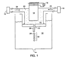
- the internal phase 10 that is a fluid (such as an oil) that contains particles 20 is ejected through an aperture 22 into the external phase 12 (such as a gelatin and acacia solution).
- the internal phase 10 is under pressure provided by a pump 18 (or pumps) and generally travels in a direction indicated by arrows 24.
- the aperture 22 has a diameter ranging from about 10 ⁇ m to about 500 ⁇ m. Ejection is controlled such that the internal phase 10 forms a jet 26 that issues into the external phase 12.
- a vibrating member 14, such as a piezoelectric transducer, is driven at a frequency by a voltage source 16 and is used to impart a vibration to the jet 26.
- the jet 26 disintegrates into a train 30 of substantially monodisperse droplets 28 (only one droplet 28 is labeled) according, in part, to the frequency of the vibration.
- the frequency depends upon the aperture 22 size and the flow rate of the internal phase 10.
- This system has a large throughput. For example, at least about 300 ml/hr of about 250 ⁇ m diameter internal phase droplets can be processed. Furthermore, this embodiment can be scaled up and is suited to continuous manufacturing processes.
- FIG. 3-5 another embodiment of the invention, similar in function to that shown in Figure 1 , vibrates and ejects an internal phase to form substantially uniformly sized droplets.
- Two tubes 70, 72 enter a sheath 78 that surrounds the apparatus 100 to allow the apparatus 100 to be submerged in an external phase while keeping the components within the apparatus 100 dry.
- the tubes 70, 72 screw into an upper plate 92.
- the tubes 70, 72 can be connected with the upper plate 92 in other manners, such as bonding.
- the tubes 70, 72 align with apertures in the upper plate 92.
- a diaphragm 84 is located between the upper plate 92 and a lower plate 94.
- the apertures in the upper plate 92 align with apertures in the diaphragm 84 and align with the ends 171, 173 of two channels 170, 172 that are formed in the top surface of the lower plate 94.
- the diaphragm 84 encloses the channels 170, 172 by covering their tops at the top surface of the lower plate 92.
- the channels 170, 172 lead to an ejection chamber 90 and an aperture 86 (which can have a particular shape) leading out of the apparatus 100.
- the ejection chamber 90 tapers from a large diameter circle to a smaller diameter circle as one moves from the diaphragm 84 to the aperture 86.
- Screws 96 are positioned such that they are located adjacent to the channels 170, 172 and the ejection chamber 90 to clamp the upper 92 and lower 94 plates together.
- the position of the screws 96 allows for a tight seal between the plates 92, 94 without the use of seals such as "O-rings.”
- the plates 92, 94 are typically constructed from a metal so that the screws' 96 clamping force creates a metal face seal.
- the aperture 86 can be constructed separately from the lower plate 92 and subsequently affixed to the lower plate 92 where the ejection chamber 90 terminates. Alternatively, the aperture 86 can be constructed directly in the lower plate 92.
- a vibrating member 80 such as a piezoelectric transducer, facilitates ejection of an internal phase into an external phase in a train 30 of substantially uniformly-sized droplets 28.
- the vibrating member 80 is mounted on a carriage, and a diaphragm 84 transmits vibration from the vibrating member 80 to the internal phase located in the ejection chamber 90.
- the lower plate 94, diaphragm 84, and upper plate 92 are sealed 82, and the upper plate 92 and the sheath 78 are sealed 82.
- the apparatus 100 initially is primed so that the internal phase fills the components of the apparatus 100 such that the apparatus 100 is substantially free from air bubbles.
- the apparatus 100 is primed by flushing the internal phase from a pressurized reservoir, through a three-way valve 96a, the inlet tube 70, the channels 170, 172 and ejection chamber 90, the outlet tube 72, and a second three-way valve 96b to exhaust the internal phase.
- the function of the outlet tube 72 is switched by adjusting three-way external valves 96a, 96b so that internal phase flows to the outlet tube 72 through the three-way valve 96b, causing the outlet tube 72 to act as an inlet.
- the internal phase enters into the apparatus 100 through both the inlet tube 70 and the outlet tube 72 (now acting as a second inlet tube).
- the internal phase is stored in and moves from a pressurized reservoir.
- the reservoir should be stirred or otherwise mixed to prevent the particles within the internal phase dispersion from settling under gravity.
- the internal phase can be agitated by mechanical stirring and/or sonication.
- Mechanical stirring is useful, for example, for mixing the internal phase down to the smallest length scales of turbulent flow and sonication is useful, for example, for breaking up agglomerations of particles on an even smaller scale.
- mixing can agitate materials of a certain size down to a lower bound that is determined by the size limit of turbulent flow properties. At least below this lower bound of size (and perhaps above this bound), sonication can agitate materials that are of this size that is less than the lower bound.
- the particles in the internal phase can be designed such that their chemical composition aids in keeping them separated from each other. For example, the particles can be constructed to exhibit stearic repulsion between particles.
- the internal phase flows to the slender inlet/outlet tubes 70, 72 of the emulsification system.
- the internal phase passes down the inlet/outlet tubes 70, 72, into the beginnings 171, 173 of the channels that are aligned with the inlet/outlet tubes 70, 72, and through the curved channels 170, 172 (in a direction indicated by arrows 180).
- the channels 170, 172 are machined into the surface of the lower plate 94 (best shown in Figure 4 ).
- the geometry of each channel 170, 172 is chosen to encourage further mixing of the internal phase. For example, flow through a curved channel induces a secondary flow that mixes the fluid(s) and particle(s) in the internal phase.
- this secondary flow is shown schematically as a plurality of continuous loop arrows 182 (only one is labeled) in an enlarged schematic view of one of the curved channels 170.
- the curved channels 170, 172 are used to maximize turbulent mixing in order to maintain the compositional uniformity of the internal phase, a flowing dispersion of one or more fluids and one or more species of particles.
- the Reynold's number should be larger than, for example, about 2000.
- ⁇ is the internal phase dispersion density
- U is the mean velocity of the dispersion in the channel
- L is a characteristic dimension of the channel, such as the hydraulic diameter (the ratio of the cross sectional area A c of the channel to the wetted perimeter P c of the channel)
- ⁇ is the viscosity of the dispersion.
- the internal phase dispersion can exhibit non-Newtonian behavior in some situations.
- Application of a shear force to the internal phase (such as by pressurizing the internal phase to move it through the apparatus 100), in some instances, can cause viscosity of the internal phase to decrease relative to its viscosity when no shear force is applied.
- ⁇ may be taken as an effective viscosity (i.e ., the viscosity when shear force is applied) and can be calculated in accordance with standard techniques known in the field.
- ⁇ is about 1090 kg/m 3 and ⁇ is about 2 x 10 -3 Pa ⁇ s.
- Equations 1 and 2 are mathematically equivalent, but mathematically transformed relative to each other. These calculations are exemplary and are not intended to be limiting.
- Re 1090 0.002 ⁇ UAc P c > 2000 or UAc P c > 3.7 ⁇ 10 - 3 ⁇ m 2 / s .
- the constraint of (1) or (2) bounds the minimum mean velocity of the internal phase in the channel.
- the required flow rate of the system is fixed, and design the channel geometry to meet the constraint of (1) or (2).
- the aperture 86 and curved channels 170, 172 should not become clogged with the solid particles in the internal phase.
- the diameter of an aperture 86 and the cross-sectional area of the curved channels 170, 172 should be at least about 5 times, and preferably about 10 times, the diameter of the largest solid particles in the system.
- the shape of the aperture 86 and the curved channels 170, 172 should not change over time due to an abrading effect of the flowing internal phase.
- the aperture geometry may be selected from a wide variety of configurations, but it is preferable to use a smooth entrance to the aperture 86 from the ejection chamber 90 in this apparatus 100, as opposed to a sharp edge, to achieve longer aperture service-life. Smooth aperture entrances are preferable because, at high flow rates, the particles in the internal phase will gradually abrade any sharp edges, thereby modifying, as a function of service time, the aperture performance of those apertures with sharp edges. Additionally, the aperture 86 can be made from, or coated with, an abrasion-resistant material such as stainless steel or sapphire.
- the apparatus 100 is operated in order to produce droplets of the internal phase containing particles that issue into an external phase.
- two methods exist in ink jet technology to produce drops of ink "drop-on-demand” and “continuous-jet.”
- Conventional drop-on-demand ink jet printers are activated by sending a voltage pulse to a piezoelectric transducer, which rapidly pressurizes the fluid in a small chamber.
- the fluid issues forth from an aperture attached to the chamber, thus ejecting a single drop on a time scale of about 5 ⁇ s to 10 ⁇ s. After ejection, the system is allowed to re-equilibrate over a longer time scale (approximately 50 ⁇ s to 10,000 ⁇ s).
- the drop-on-demand method contrasts with conventional continuous jet ink jet devices, in which a pressurized fluid is jetted from an aperture, and the vibrations of a piezoelectric transducer excite a capillary instability in the jet.
- neither of these methods is appropriate for jetting the internal phase into a stationary external phase.
- Drop-on-demand systems do not impart adequate momentum to the ejected drops to enable them to be injected into a viscous external phase.
- Continuous jet systems are inadequate because the intensity of the capillary instability is reduced substantially by the presence of the external phase.
- Capillary instability is the phenomenon whereby a jet of fluid issuing from an aperture becomes unstable.
- the apparatus 100 employs a technique for ejecting individual drops at high speed.
- the internal phase is pressurized to a static pressure P, and the piezoelectric transducer 80 is oscillated by a periodic voltage signal.
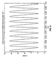
- the pressure and the piezoelectric excitation voltage signal are selected such that the flow rate from the aperture varies in manner similar to the profile shown in Figure 6.
- Figure 6 shows the velocity ("U") of the expelled internal phase over time (“t").
- the profile of Figure 6 can occur when the pressure of the internal phase is properly matched to the frequency and amplitude of the signal applied to the piezoelectric transducer 80 and when the ejection rate is about 1000 droplets/second.
- ejection velocity varies transiently from about zero to about 21 m/s.
- This profile indicates that a slug of the internal phase, ejected from the aperture 86 at high speed, pinches-off near the aperture 86 due to the pulsatile flow imposed by the piezoelectric transducer 80. That is, the internal phase is ejected at high speed (a peak of the sinusoidal wave in Figure 6 ) and pinches off when the velocity of the internal phase approaches zero (a trough of the sinusoidal wave in Figure 6 ).
- Velocity of the internal phase is controlled by the static pressure of the system that moves the internal phase through the passageways of the apparatus 100 and the dynamic pressure of the vibrating member 80 that is superimposed on the static pressure.
- the dynamic pressure allows the system to oscillate between a high and low velocity.
- Figure 6 is exemplary and is not meant to be limiting.
- the velocity of the internal phase need not reach zero to create controlled disintegration of the jet of internal phase and the velocity of the internal phase can be considered high velocity at other values of velocity. These upper and lower values depend upon many variables such as the internal phase used. For example, it is contemplated that a decrease to even about 5 m/s from a higher velocity can create this controlled disintegration of the jet.
- performance of the apparatus 100 is distinct from a drop-on-demand ink jet, because it is operated in a continuous manner and typically does not reequilibrate to an at-rest condition.
- performance of the apparatus 100 is distinct from a continuous ink jet, because the continuous ink jet solely relies upon capillary instability of an issued jet to form individual drops.
- the apparatus 100 is driven in a different manner from continuous ink jets, resulting in droplets that form within about a few droplet diameters of the aperture through which it issues.
- the internal phase is both pressurized and subjected to piezoelectric generated vibrations to create an oscillating pinching off of droplets at the aperture, while, in continuous ink jets, the vibration is tuned to enhance Rayleigh instability.
- the present invention combines high through-put with controlled droplet formation, and overcomes the problems with current ink-jet technology as described above.
- the apparatus 100 shown in Figures 3-5 is sensitive to a large number of design parameters and operating conditions.
- Some adjustable parameters include vibration of the vibrating member 80 (such as a piezoelectric transducer), the size and shape of the ejection chamber 90, the size and shape of the aperture 86, the size and shape of the channels 170, 172, and the size and thickness of the diaphragm 84.
- the vibrating member 80 must be designed so that it displaces a satisfactorily large portion of the volume of the chamber 90 from which the internal phase is ejected.
- the maximum volumetric displacement (“ ⁇ V max ”) of the internal phase in the ejection chamber 90 by the vibrating member 80 (via the diaphragm 84) is approximately given by: ⁇ ⁇ V max ⁇ ⁇ ⁇ V - ⁇ ⁇ P
- ⁇ is a property of the vibrating member 80 and is a coefficient relating displacement to applied voltage ("V")
- ⁇ is related to the radius of the ejection chamber and is a coefficient relating displacement to fluid pressure ("P").
- the design in certain embodiments should comply with the equation: ⁇ ⁇ V > ⁇ ⁇ P in order to provide useful operation of the apparatus 100.
- ⁇ V describes the maximum amount of volume displacement by the vibrating member 80 (and diaphragm 84) in the absence of the fluid pressure, P, and ⁇ P describes the pressure that works opposite the pressure from the vibrating member 80.
- designs of the invention must have a positive ⁇ V max to operate (i.e ., internal phase must be displaced out of the ejection chamber 90 so that the internal phase issues out of the aperture 86) and, for that to occur, the diaphragm deflection resulting from the application of voltage to the vibrating member 80 must be greater than the diaphragm deflection resulting from the static pressure of the internal phase in the ejection chamber 90.
- V ranges from about 50 to about 300 volts
- P ranges from about 5 to about 50 psi.
- P can be increased if the seals 82 of the apparatus 100, as well as other components of the apparatus, are sufficient to support such pressure.
- the range of P depends, in part, upon the mechanical properties of the materials used to construct the apparatus 100, and it is contemplated that this range of P values will be expanded based upon choosing materials and designs that increase the integrity of the apparatus 100 under higher pressures.
- High pressure operation is useful because it enables higher through-put emulsification, forming more substantially uniformly-sized droplets of internal phase per time period than the amount formed at lower operating pressures.
- the nominal conditions described above enable several liters of internal phase per hour to be emulsified through a single aperture unit. Adding additional apertures also can allow higher throughput operation.
- the vibration can be tuned to intentionally make two species of monodisperse droplets at the same time.
- the apparatus can make two types of droplets where a droplet of one type is substantially uniformly-sized relative to other droplets of that type while a droplet of a second type is substantially uniformly-sized relative to other droplets of that type.
- the vibration can be tuned to make a group of droplets of about 300 ⁇ m and a group of smaller droplets.
- two sizes of substantially uniformly-sized droplets emerge from the same aperture one after the next according to a pattern ( e.g ., alternating large and small droplets).
- the ejection chamber 90 radius plays a role in determining the coefficients ⁇ and ⁇ . It is preferable to make the radius as large as possible to maximize the displacement of the internal phase, but for high speed operation, it is preferable to use a small radius. Thus, a balance needs to be reached to both maximize the displaced volume of the internal phase and to maximize the throughput of internal phase.
- the radius of the chamber 90 ranges from about 1 mm to about 10 mm.
- other radii are contemplated for other embodiments of the present invention, depending upon this balance of displacement volume and speed of operation, as well as the interplay with other variables.
- the length and cross-sectional area of the channels 170, 172 also are controllable variables.
- the channels 170, 172 can range in length from about 0.25 mm to about 15 mm, with cross-sectional areas ranging from about 20,000 ⁇ m 2 to about 500,000 ⁇ m 2 .
- the cross-sectional area of the channels 170, 172 can be reduced to increase the Reynold's number to enhance mixing.
- the channels 170, 172 can be fabricated using conventional machining, chemical etching, photolithographic processes, reactive ion etching, scribing, or any other technology useful for precision machining and microfabrication.
- the aperture 86 can have a diameter ranging from about a few ⁇ m to about several hundred ⁇ m or more, and preferably about 25 ⁇ m to about 200 ⁇ m. These apertures can be manufactured using techniques for precision machining or microfabrication, and can be constructed separately from the lower plate 94 and later affixed to the lower plate 94 or can be constructed from the lower plate 94 itself.
- the diaphragm 84 can be made from any material that is able to deflect under pressure from the vibrating member 80 and that has a suitable resiliency and stiffness (to avoid permanent deformation) during use to provide a reasonable service-life.
- a material that is useful as the diaphragm 84 is a stainless steel foil having a thickness ranging from about several ⁇ m to about several hundred ⁇ m, and preferably about 25 ⁇ m to about 100 ⁇ m. Thinner foils are preferred, but foils that are too thin will tend to rupture or otherwise permanently deform during aggressive use.
- materials that are useful as the diaphragm 84 are polyimides, such as Kapton (available from E. I. du Pont de Nemours and Company, Wilmington, DE).
- the apparatus 100 described above enables substantially uniformly-sized droplets of internal phase to be ejected into an external phase.
- the resulting emulsion can be encapsulated to create an encapsulated electrophoretic display material, as described above.
- complex coacervation can be used.
- a variety of encapsulation techniques can be used.
- encapsulation may be effected by in situ polymerization utilizing an oil/water emulsion, which is formed by dispersing the internal phase (e.g ., a dielectric liquid containing a suspension of pigment particles) in the aqueous environment of the external phase.
- the internal phase e.g ., a dielectric liquid containing a suspension of pigment particles
- Monomers polymerize to form a polymer with higher affinity for the internal phase than for the aqueous external phase, thus condensing around the emulsified oily droplets.
- in situ polymerization is that between urea and formaldehyde in the aqueous external phase of the oil (internal phase)/water (external phase) emulsion in the presence of a negatively charged, carboxyl-substituted, linear hydrocarbon polyelectrolyte material, such as poly (acrylic acid).
- the resulting capsule wall is a urea/formaldehyde copolymer, which discretely encloses the internal phase.
- the capsule is clear, mechanically strong, and has good resistivity properties.
- Other useful cross-linking agents for use in such processes include aldehydes, especially formaldehyde, glyoxal, or glutaraldehyde; alum; zirconium salts; and poly isocyanates.
- the coacervation approach also utilizes the oil/water emulsion of the internal and external phases.
- One or more colloids are coacervated (i.e ., agglomerated) out of the aqueous external phase and deposited as shells around the oily droplets of the internal phase through control of temperature, pH and/or relative concentrations, thereby creating the capsule.
- Materials suitable for coacervation include gelatins and gum arabic.
- the interfacial polymerization approach relies on the presence of an oil-soluble monomer in the internal phase, which once again is present as an emulsion in the aqueous external phase.
- the monomers in the internal phase droplets react with a monomer introduced into the aqueous external phase, polymerizing at the interface between the internal phase droplets and the surrounding aqueous external phase and forming capsule walls around the droplets.
- the resulting walls are relatively thin and may be permeable, this process does not require the elevated temperatures characteristic of some other processes, and therefore affords greater flexibility in terms of choosing the dielectric liquid.
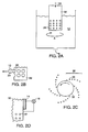
- the internal phase 10 containing a fluid and particles 20, as described above is fed into a hollow tube 32 according to arrow 34.
- the tube 32 is perforated along its outer surface with a plurality of small apertures 22. The diameter of these apertures can range from about 10 ⁇ m to about 500 ⁇ m.
- the tube 32 is spun in direction A at a particular rate, and the forces associated with the tube 32 rotation cause the internal phase 10 to extrude out through the apertures 22 (best shown in Figure 2B ).
- droplets 28 of the internal phase 10 break off from the remainder of the internal phase 10 due to viscous interaction between internal phase 10 and the surrounding external phase 12.
- a number of trains 30 (only one train 30 is labeled) of droplets 28 are produced (best shown in Figure 2C ).
- the external phase may be set into motion, and the perforated tube may be held at rest. As the internal phase flows out of the tube, the relative motion of the internal phase and the external phase results in a train of droplets, as described above.
- a vibrating member 14 such as a piezoelectric transducer, can be combined with the perforated tube 32 ( Figure 2D ).
- the vibrating member 14 is excited, for example, with a source of voltage 16, and vibrates the internal phase to facilitate droplet production from the apertures 22. More particularly, the internal phase is forced through the perforated tube 32 such that a plurality of jets issue radially outward from the tube 32.
- the tube 32 is excited along its centerline axis (perpendicular to the axis of the jets). Vibrations are imparted to each of the jets, simultaneously, causing them to break up into several trains of substantially uniformly-sized droplets.
- FIG. 2A-2D offers similar advantages to those described above for Figures 1 and 3-7 and also offers the advantage that the rotation of the tube 32 allows fresh external phase 12 to be transported to the aperture 22 region in a continuous manner. Because it is difficult to maintain sufficient concentrations of stabilizing agents, such as sodium dodecylsulfate, very near to an aperture in many emulsification systems, the rotating tube 32 allows these stabilizing agents to be presented to regions near an aperture 22.
- Other similar designs can include rotating or oscillating perforated structures, such as spheres or plates, or systems that otherwise allow the external phase to flow past an aperture to replenish the local concentration of stabilizing agents.
- complex droplets or capsules can be collected in an appropriate liquid for storage. Because the capsules are eventually mixed with a binder and coated onto a flat surface, the complex droplets or capsules can be collected into the binder directly, or into a material which is readily miscible with the binder. In the case of water-based binders, this fluid can be water. Measures can be taken to prevent the complex droplets or capsules from sticking to one another in the collection liquid. Surfactants and/or dispersing agents can be used in the collection liquid to prevent the complex droplets or capsules from sticking to each other. Also, the collection liquid can be a quiescent reservoir positioned below the jet of external and internal phase so that capsules with hardened walls will fall into the collection liquid.
- capsules can be formed as a dry powder that is mixed with a liquid binder for coating onto a substrate.
- a liquid binder for coating onto a substrate.
- aggregates of capsules impair coating performance.
- capsules should be prevented from sticking to one another, or, if the capsules are not prevented from sticking to one another, the adhesion can be reversed when the capsules are mixed with binder.
- a pair of immiscible fluids can be mixed into a droplet, before a separate encapsulation step to form a capsule containing two immiscible fluids, using two concentric nozzles that are in communication with a pump.
- One of the fluids is expelled through one of the nozzles, and the other fluid is expelled through the other nozzle.
- This droplet can then be encapsulated, assuming the fluids are chemically compatible with the encapsulation solvent, by, for example, gelatin/acacia encapsulation.
- a physical coextrusion process can be used to encapsulate the droplet.
- three concentric nozzles are attached to a pump.
- the droplets can be formed by pumping a dye-containing fluid solution through the inner nozzle, a particle dispersion-containing fluid through the middle nozzle, and an encapsulating polymer (as a solution or a melt) through the outer nozzle.
- an encapsulating polymer as a solution or a melt
- capsules are formed.
- the capsules can be hardened by evaporating a solvent or solvents used during the pumping procedure or, if any of the materials are pumped through the nozzle at a temperature greater than the ambient temperature, by cooling the capsules.
- a capsule with two immiscible fluids, one containing particles is produced.
- unencapsulated droplets or encapsulated droplets During formation of unencapsulated droplets or encapsulated droplets according to the invention, several variables can be manipulated, depending upon, for example, the materials used.
- the dyed-fluid is pumped through the central nozzle and a second immiscible fluid containing dispersed particles is pumped through the outer nozzle, forming droplets.
- the droplets are extruded into an aqueous phase that has been prepared for encapsulation, described below.
- the droplets can be made one at a time using relatively low flow rates of the fluids through the nozzles, or the fluids can be coextruded at relatively higher flow rates, for example, as a liquid jet that breaks up by Rayleigh instability into individual droplets.
- droplet formation can be assisted by vibration of the concentric nozzles using, for example, a piezoelectric stack.
- the spreading coefficients of the various liquids can be controlled.
- the spreading coefficient is a description of how one fluid spreads over another fluid.
- liquid B refers to the wall forming liquid extruded from the outermost nozzle.
- Liquid A and liquid B remain the two immiscible fluids from above.
- interfacial tensions in the three-nozzle system are set such that the encapsulating material preferentially wets the particle dispersion-containing fluid and/or such that the particle dispersion-containing fluid will preferentially wet the dye-containing fluid.
- variables that can be altered, depending upon the particular compounds employed in droplet formation and encapsulation include pumping rate, flow rate, and viscosity.
- pumping rate typically, at least one of the pumping rates through one nozzle is different from another one of the pumping rates through a different nozzle.
- the flow rate of materials through the nozzles, relative to each other, as well as the overall flux of material through the nozzles, can be varied.
- the viscosity of the materials coming through the nozzles can affect the final morphology of the droplets.
- the apertures e.g ., nozzles
- the apertures should be aligned so that they are concentric.
- two or more apertures can be aligned concentrically with high precision.
- the apertures can be on the same or on different planes.
- the technique can be used to ensure that an array of apertures aligns concentrically with another array of apertures.
- a kinematic coupling is used to precisely maintain the spacing between and alignment of multiple plates containing apertures.
- a kinematic coupling typically is used for very large objects (e.g., metrology frames used in large, precision machines) rather than small objects, such as the plates with apertures used in coextrusion as described above.
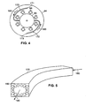
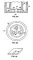
- the kinematic coupling is composed of the plates 120, 122, each plate 120, 122 with an aperture 124, 144 and with three triangular cross-section grooves 126, 128, 130, 132, 134, 136 (best shown in Figure 8B as section A-A through one of the grooves 128 of Figure 8A ) in the surface of each plate 120, 122, and spherical balls 138, 140, 142 rigidly affixed in the grooves of one plate 122.
- the coupling maintains repeatable, precise alignment by providing 6 contact points (often referred to as "bearing surfaces") between the surfaces of the balls 138, 140, 142 and the plates 120, 122.
- the geometry of the coupling is chosen so that the six contact points fully constrain the motion of the plates 120, 122 with respect to one another.
- Figures 9A and 9B show a coextrusion system aligned with the kinematic technique.
- a first plate 146 with grooves 132, 134, 136 and balls 138, 140, 142 and an aperture 144 is aligned with a second plate 148 with a second aperture 150.
- Adjacent channels 152, 154 are formed within the plates 146, 148.
- the balls can be replaced with other shapes, such as cylinders with hemispherical ends.
- crystalline silicon wafers may be patterned, using photolithography techniques, to produce triangular cross-section trenches 158. These trenches may be used as the grooves for the kinematic coupling. Similar techniques can be used on coextrusion plates. Aperture holes may be drilled through the plates using many techniques, such as wet etching, dry etching, or laser drilling techniques.
- the balls for kinematic alignment may be made from such materials as alumina, sapphire, or ruby.
- the balls can be attached to the plates using techniques such as high temperature bonding or epoxy bonding.
- the ball diameter influences the stiffness of the kinematic coupling and also controls the separation distance between the surfaces of the two plates. This distance between the two plates influences the flow of fluid through the gap between the plates. A smaller gap corresponds with a higher pressure drop and a larger gap corresponds with a lower pressure drop. A very large pressure drop in the system is undesirable, as is turbulence in some embodiments.
Description
- The invention generally relates to methods for producing large quantities of substantially monodisperse droplets for use in capsule-based electrophoretic displays. More particularly, the methods relate to producing substantially uniformly-sized droplets of a first phase, the first phase including a fluid and particles, for introduction into a second phase, or the methods relate to producing substantially uniformly-sized complex droplets having a core formed from a first phase, the first phase including a fluid and particles, and a second phase that surrounds the first phase as a shell.
- Traditional emulsification methods are not ideally suited for forming capsules to be used in electrophoretic displays. Current methods produce disperse phase droplets that are smaller than the desired size range. For example, while some systems produce droplets as large as tens of micrometers in diameter, typical droplets are of the order of 0.01 µm to 1 µm. Furthermore, many traditional emulsification techniques result in polydisperse emulsions, i.e., emulsions that are not characterized by a narrow drop size distribution. Thus, a need exists to produce substantially uniformly-sized droplets for forming capsules to be used in electrophoretic displays.
-
EP-A-778 083 - Methods of the invention can produce large quantities of substantially uniformly-sized droplets or complex droplets for forming capsules useful for electrophoretic displays. Moreover, methods of the invention can produce a group of substantially uniformly-sized droplets from a first phase containing both a fluid and plurality of particles. These droplets are applied to a second phase. Once in contact with the second phase, any of a variety of steps can be performed, including encapsulating the droplets. Alternatively, methods of the invention can produce a group of substantially uniformly-sized complex droplets for forming capsules useful for forming electrophoretic displays. The complex droplets are formed from a first phase, containing both a fluid and a plurality of particles, at their core and a second phase that surrounds the first phase as a shell. Typically, the core of the complex droplet also is a substantially uniformly-sized droplet relative to the other cores in the group of complex droplets.
- In one aspect, this invention provides a method for forming substantially uniform droplets of a first liquid phase in a second liquid phase immiscible with the first phase by passing a stream of the first phase below the surface of the second phase and causing the this stream to break up into droplets. In this method:
- the first phase is a non-aqueous internal phase comprising a plurality of particles suspended in a first fluid;
- the second phase is an external phase capable of being solidified to form a microcapsule wall and comprising a second fluid; and
- the first phase is placed under pressure within a chamber having an aperture which emerges below the surface of the second phase and a vibrating member vibrates towards and away from the aperture to cause the stream to break up into droplets.
- In another aspect, this invention provides a method for forming substantially uniform droplets of a first liquid phase in a second liquid phase immiscible with the first phase by passing the first phase below the surface of the second phase. In this method:
- the first phase is a non-aqueous internal phase comprising a plurality of particles suspended in a first fluid;
- the second phase is an external phase capable of being solidified to form a microcapsule wall and comprising a second fluid;
- the first phase is placed within a container at least partially immersed in the second phase, the container having a least one aperture extending therethrough and opening below the surface of the second phase; and
- the container is rotated relative to the second phase so that the first phase is extruded through the aperture into the second phase and forms a plurality of the droplets within the second phase.
- The invention is more particularly described in the following detailed description, drawings, and claims. In the drawings, like reference characters generally refer to the same parts throughout the different views. Also, the drawings are not necessarily to scale, emphasis instead generally being placed upon illustrating principles of the invention.
-
Figure 1 depicts a schematic drawing of a device including a piezoelectric transducer that is driven at a particular frequency to impart vibration to a jet of an internal phase to produce a train of monodisperse droplets of the phase. -
Figure 2A depicts a schematic drawing of a device that forms droplets of an internal phase by issuing the phase through holes in a hollow tube that is spun at a particular rate. -
Figure 2B depicts a schematic enlarged view of a droplet emerging from an aperture in a section of the tube ofFigure 2A . -
Figure 2C depicts a schematic top view of the tube ofFigure 2A and droplets emerging from various apertures in the tube. -
Figure 2D depicts a schematic enlarged view of a section of an alternative embodiment of the device ofFigure 2A in which the tube is spun and vibrated. -
Figure 3 depicts a schematic sectional side view of an apparatus to produce substantially uniformly sized droplets of an internal phase with a vibrating member. -
Figure 4 depicts a top sectional view taken generally along the line of a diaphragm of the embodiment ofFigure 3 showing curved channels to promote mixing of the internal phase as it is delivered to an ejection chamber. -
Figure 5 depicts a schematic enlarged view of a cross-section of one curved channel ofFigure 4 . -
Figure 6 shows the velocity of an internal phase expelled from the embodiment shown inFigure 3 when the pressure of the internal phase is matched to the frequency and amplitude of the signal applied to a piezoelectric transducer when the ejection rate is about 1000 droplets/second. -
Figure 7 shows the velocity of an internal phase expelled from the embodiment shown inFigure 3 when the pressure of the internal phase is not ideally matched to the frequency and amplitude of the signal applied to a piezoelectric transducer when the ejection rate is about 1000 droplets/second. -
Figure 8A shows a schematic top view of a plate for kinematic alignment. -
Figure 8B shows a schematic section along line A-A through the plate shown inFigure 8A . -
Figure 8C shows a schematic side sectional view of the plate ofFigure 8A . -
Figure 8D shows a schematic side sectional view of the plate ofFigure 8A aligned with a second plate. -
Figure 9A shows a schematic side sectional view of two aligned coextrusion plates. -
Figure 9B shows a schematic end view of the plates ofFigure 9A . -
Figure 10 shows schematic view of a triangular cross-section trench produced with photolithography and etching. - The invention relates to the application of a liquid dispersion (oil-based or aqueous and hereinafter referred to as the "internal phase") to another liquid (aqueous or oil-based and hereinafter referred to as the "external phase"). Generally, the internal phase is non-aqueous, contains particles, and is issued from a structure containing the internal phase such that substantially uniform droplets or substantially uniform complex droplets are produced. When the internal phase issues from the structure, it is either applied simultaneously to the external phase or applied to the external phase at a different time from issuance. In certain embodiments, when the internal phase is issued into an external phase, the liquid dispersion of the internal phase is emulsified in the external phase. This emulsification technique, for example, can be used to form a series of substantially uniformly-sized droplets of the internal phase for encapsulation by components in the external phase to produce capsules for electrophoretic displays. In other embodiments, when the internal and external phases are issued simultaneously through adjacent, concentric nozzles, a series substantially uniformly-sized complex droplets (droplets with an internal phase core and a thin external phase shell) are produced. These complex droplets also can be encapsulated by hardening the external phase shell. Typically, the cores of these complex droplets also are substantially uniformly sized. Thus, methods of the invention contribute to the progression of capsule-based electrophoretic display technology toward high through-put, high quality capsule production.
- Taking a step back, electrophoretic displays have been the subject of intense research and development for a number of years. Electrophoretic displays have attributes of good brightness and contrast, wide viewing angles, state bistability, and low power consumption when compared with liquid crystal displays. Nevertheless, problems with the long-term image quality of these displays have prevented their widespread usage. For example, particles that make up such displays tend to cluster and settle, resulting in inadequate service-life for these displays.
- An encapsulated electrophoretic display typically does not suffer from the clustering and settling failure mode of traditional electrophoretic devices and provides further advantages, such as the ability to print or coat the display on a wide variety of flexible and rigid substrates. Use of the word "printing" is intended to include all forms of printing and coating, including, but without limitation: premetered coatings such as patch die coating, slot or extrusion coating, slide or cascade coating, and curtain coating; roll coating such as knife over roll coating, forward and reverse roll coating; gravure coating; dip coating; spray coating; meniscus coating; spin coating; brush coating; air knife coating; silk screen printing processes; electrostatic printing processes; thermal printing processes; ink jet printing; and other similar techniques. Thus, the resulting display can be flexible. Further, because the display media can be printed (using a variety of methods), the display itself can be made inexpensively.
- In broad overview, encapsulated electrophoretic displays provide a flexible, reflective display that can be manufactured easily and consumes little power (or no power in the case of bistable displays in certain states). Such displays, therefore, can be incorporated into a variety of applications. The display can be formed from and can include particles that move in response to an electric charge. This mode of operation is typical in the field of electrophoretic displays. A display in which the particles, ordered by an electric charge, take on a certain configuration can take on many forms. Once the electric field is removed, the optical state of the particles can be generally stable (e.g., bistable). Additionally, providing a subsequent electric charge can alter a prior configuration of particles. Some encapsulated electrophoretic displays may include two or more different types of particles. Such displays may include, for example, displays containing a plurality of anisotropic particles and a plurality of second particles in a suspending fluid. Application of a first electric field may cause the anisotropic particles to assume a specific orientation and present an optical property. Application of a second electric field may then cause the plurality of second particles to translate, thereby disorienting the anisotropic particles and disturbing the optical property. Alternatively, the orientation of the anisotropic particles may allow easier translation of the plurality of second particles. The particles may have a refractive index that substantially matches the refractive index of the suspending fluid.
- An encapsulated electrophoretic display can be constructed so that the optical state of the display is stable for some length of time. When the display has two states that are stable in this manner, the display is bistable. If more than two states of the display are stable, then the display is multistable. For the purpose of the present invention, the term bistable indicates a display in which any optical state remains fixed once the addressing voltage is removed. However, the definition of a bistable state depends upon the display's application. A slowly decaying optical state can be effectively bistable if the optical state is substantially unchanged over the required viewing time. For example, in a display that is updated every few minutes, a display image that is stable for hours or days is effectively bistable for a particular application. Thus, for purposes of the present invention, the term bistable also indicates a display with an optical state sufficiently long-lived so as to be effectively bistable for a particular application. Alternatively, it is possible to construct encapsulated electrophoretic displays in which the image decays quickly once the addressing voltage to the display is removed (i.e., the display is not bistable or multistable). Whether or not an encapsulated electrophoretic display is bistable, and its degree of bistability, can be controlled through appropriate chemical modification of the electrophoretic particles, the suspending fluid, the capsule, and binder materials.
- An encapsulated electrophoretic display may take many forms. The display may include capsules dispersed in a binder. The capsules may be of any size or shape. The capsules may, for example, be spherical and may have diameters in the millimeter range or the micron range, but are preferably from about ten to about a few hundred microns. The capsules may be formed by an encapsulation technique. Particles may be encapsulated in the capsules. The particles may be two or more different types of particles. The particles may be colored, luminescent, light-absorbing or transparent, for example. The particles may include neat pigments, dyed (laked) pigments or pigment/polymer composites, for example. The display may further include a suspending fluid in which the particles are dispersed.
- Generally, an encapsulated electrophoretic display includes a capsule with one or more species of particle that either absorb or scatter light and that are suspended in a fluid. One example is a system in which the capsules contain one or more species of electrophoretically mobile particles dispersed in a dyed suspending fluid. Another example is a system in which the capsules contain two separate species of particles suspended in a clear suspending fluid, in which one species of particle absorbs light (black), while the other species of particle scatters light (white). There are other extensions (more than two species of particles, with or without a dye, etc.). The particles are commonly solid pigments, dyed particles, or pigment/polymer composites.
- In electrophoretic displays, the particles may be oriented or translated by placing an electric field across the capsule. The electric field may include an alternating-current field or a direct-current field. The electric field may be provided by at least one pair of electrodes disposed adjacent to a display comprising the capsule.
- The successful construction of an encapsulated electrophoretic display requires the proper interaction of all these materials and processes. Materials such as a polymeric binder (for example, for binding the capsules to a substrate), electrophoretic particles, fluid (for example, to surround the electrophoretic particles and provide a medium for migration), and a capsule membrane (for example, for enclosing the electrophoretic particles and fluid) must all be chemically compatible. The capsule membranes may engage in useful surface interactions with the electrophoretic particles, or may act as an inert physical boundary between.the fluid and the binder. Polymer binders may set as adhesives between capsule membranes and electrode surfaces.
- Various materials may be used to create electrophoretic displays. Selection of these materials is based on the functional constituents of the display to be manufactured. Such functional constituents include, but are not limited to, particles, dyes, suspending fluids, stabilizing/charging additives, and binders. In one embodiment, types of particles that may be used to fabricate suspended particle displays include scattering pigments, absorbing pigments and luminescent particles. Such particles may also be transparent. Exemplary particles include titania, which may be coated in one or two layers with a metal oxide, such as aluminum oxide or silicon oxide, for example. Such particles may be constructed as corner cubes. Luminescent particles may include, for example, zinc sulfide particles. The zinc sulfide particles may also be encapsulated with an insulative coating to reduce electrical conduction. Light-blocking or absorbing particles may include, for example, dyes or pigments. Types of dyes for use in electrophoretic displays are commonly known in the art. Useful dyes are typically soluble in the suspending fluid, and may further be part of a polymeric chain. Dyes may be polymerized by thermal, photochemical, and chemical diffusion processes. Single dyes or mixtures of dyes may also be used.
- A suspending (i.e., electrophoretic) fluid may be a high resistivity fluid. The suspending fluid may be a single fluid, or it may be a mixture of two or more fluids. The suspending fluid, whether a single fluid or a mixture of fluids, may have its density substantially matched to that of the particles within the capsule. The suspending fluid may be halogenated hydrocarbon, such as tetrachloroethylene, for example. The halogenated hydrocarbon may also be a low molecular weight polymer. One such low molecular weight polymer is poly(chlorotrifluoroethylene). The degree of polymerization for this polymer may be from about 2 to about 10.
- Furthermore, capsules may be formed in, or later dispersed in, a binder. Materials for use as binders include water-soluble polymers, water-dispersed polymers, oil-soluble polymers, thermoset polymers, thermoplastic polymers, and uv- or radiation-cured polymers.
- While the examples described here are listed using encapsulated electrophoretic displays, there are other particle-based display media that also should work well, including encapsulated suspended particles and rotating ball displays. Other display media, such as liquid crystals and magnetic particles, also can be useful.
- In some cases, a separate encapsulation step of the process is not necessary. The electrophoretic fluid may be directly dispersed or emulsified into the binder (or a precursor to the binder material) to form what may be called a "polymer-dispersed electrophoretic display." In such displays, the individual electrophoretic phases may be referred to as capsules or microcapsules even though no capsule membrane is present. Such polymer-dispersed electrophoretic displays are considered to be subsets of encapsulated electrophoretic displays.
- In an encapsulated electrophoretic display, the binder material surrounds the capsules and separates the two bounding electrodes. This binder material must be compatible with the capsule and bounding electrodes and must possess properties that allow for facile printing or coating. It may also possess barrier properties for water, oxygen, ultraviolet light, the electrophoretic fluid, or other materials, Further, it may contain surfactants and cross-linking agents, which could aid in coating or durability. The polymer-dispersed electrophoretic display may be of the emulsion or phase separation type.
- The present invention provides materials and methods for producing these encapsulated displays, particularly by facilitating production of capsules through production of substantially uniformly-sized droplets or complex droplets. In certain embodiments the internal phase ejects into the external phase in a stream, and, due to various physical reasons, disintegrates into a train of droplets. In other embodiments, the internal phase and external phase are coextruded through adjacent, concentric nozzles, and the compound jet disintegrates into a train of complex droplets. As used herein, "train" refers to any group of two or more droplets (or complex droplets), without regard to their location to each other. Often a train of droplets (or complex droplets) is a group of droplets (or complex droplets) organized substantially along a line. However, a train of droplets (or complex droplets) need not have this orientation.
- Typically, methods of the invention produce emulsions of internal phase droplets, the droplets characterized by a narrow size distribution or produce complex droplets with an internal phase core and an external phase shell, the complex droplets characterized by a narrow size distribution. As used herein, "monodisperse" droplets (or complex droplets) refer to two or more droplets (or complex droplets) that are substantially uniformly-sized. For example, in a substantially uniformly-sized group of droplets (or complex droplets), any one droplet (or complex droplet) that has a diameter that falls within about 20%, and preferably about 5%, of the mean diameter of the group of droplets (or complex droplets) is monodisperse. Also, droplets (or complex droplets) can be made that range in diameter from about 20 µm to at least about 300 µm. These droplets (or complex droplets) can be monodisperse in relation to a particular diameter that is desired.
- Several techniques have been used to produce emulsions. These techniques include mechanical mixing techniques (e.g., colloid mills, rotor or rotor/stator systems, and static (in-line mixers), other mixing techniques (e.g., ultrasonic agitation and flow of a jet of the disperse phase over a vibrating blade) homogenization techniques (e.g., ultra high-shear mechanical mixing and flow of phases under high pressure through a small aperture), and crossflow techniques (e.g., a first phase is forced through an aperture in a capillary tube or in a membrane and into a second phase such that drops of the first phase are dislodged from the aperture by a forced motion of the second phase).
- Some of these techniques, such as mixing methods, generally do not produce a high yield of substantially uniformly-sized droplets (or complex droplets). Additionally, in situations such as production of capsules containing electrophoretically mobile particles, where the droplets (or the core of complex droplets) to be produced contain both a fluid and a solid (e.g., a suspending fluid and the electrophoretically mobile particles), methods that apply an internal phase containing the particles to the external phase, such as producing a disintegrating jet of one phase into another phase or coextruding one phase with another phase, face substantially different problems than the mere application of one fluid (or a combination of fluids) to a second fluid. For example, in the present invention in which the internal phase includes a fluid and particles, given the large area of liquid-solid interface present in the internal phase, the non-flowable nature of the solid in contrast to the flowable liquid, and the existence of frictional and/or shear forces as the liquid attempts to move relative to the solid particles, it is not apparent that applying the internal phase containing both a solid and a liquid to the external phase as described below should succeed. Additionally, methods, which include a step of vibrating the internal phase to produce droplets (or complex droplets), and which may depend upon the vibrational characteristics of a liquid, cannot inherently be transferred from a situation where the internal phase is a simple liquid to a situation where the internal phase is a fluid containing solids, because such characteristics are altered by the presence of a solid.
- Thus, although the excitation of a jet has been used previously to produce monodisperse droplets of metal, ink, monomer, and other materials, it has not been established as a common practice for forming substantially monodisperse emulsions, particularly in situations where the jet is a phase that includes a non-aqueous fluid and particles. As such, the jet disintegration method has not been used in processes relating to manufacturing capsules employed in electrophoretic displays. Additionally, although coextrusion of two or more fluids has been used to produce monodisperse complex droplets of one fluid in association with another fluid, it also has not been established as a common practice for forming substantially uniformly-sized complex droplets, the complex droplets composed of a core that includes a non-aqueous fluid containing particles and of a shell of an external phase surrounding the core. Specific advantages of forming substantially uniformly-sized droplets composed of at least a fluid and particles, or of forming substantially uniformly-sized complex droplets composed of a core including a fluid and particles and a shell of a second fluid, include the ability to produce such droplets or complex droplets at a high rate; the ability to scale production of such droplets or complex droplets; and the ability to produce substantially uniformly-sized internal phase droplets or complex droplets having mean drop sizes ranging from about 20 µm to at least about 300 µm.
- Adjustments to droplet size or complex droplet size in the various embodiments of the present invention can be made by altering the size and/or shape of the aperture through which the internal phase issues and/or the external phase issues, the pressure to which the internal phase and/or the external phase is exposed, the rotation rate of devices that rotate to produce droplets of the internal phase, and/or the frequency or amplitude at which a vibrating member is vibrated. Various systems may involve parallel plate geometry (Couette flow geometry), alternative tube flow geometry (Poiseuille flow geometry), vibrations along the axis of the jet or transverse to the jet, and dispensing from individual capillary tubes.
- Referring to
Figure 1 , in one embodiment, theinternal phase 10 that is a fluid (such as an oil) that containsparticles 20 is ejected through anaperture 22 into the external phase 12 (such as a gelatin and acacia solution). Theinternal phase 10 is under pressure provided by a pump 18 (or pumps) and generally travels in a direction indicated byarrows 24. Theaperture 22 has a diameter ranging from about 10 µm to about 500 µm. Ejection is controlled such that theinternal phase 10 forms ajet 26 that issues into theexternal phase 12. A vibratingmember 14, such as a piezoelectric transducer, is driven at a frequency by avoltage source 16 and is used to impart a vibration to thejet 26. Thejet 26 disintegrates into atrain 30 of substantially monodisperse droplets 28 (only onedroplet 28 is labeled) according, in part, to the frequency of the vibration. The frequency depends upon theaperture 22 size and the flow rate of theinternal phase 10. This system has a large throughput. For example, at least about 300 ml/hr of about 250 µm diameter internal phase droplets can be processed. Furthermore, this embodiment can be scaled up and is suited to continuous manufacturing processes. - Now referring to
Figures 3-5 , another embodiment of the invention, similar in function to that shown inFigure 1 , vibrates and ejects an internal phase to form substantially uniformly sized droplets. Twotubes sheath 78 that surrounds theapparatus 100 to allow theapparatus 100 to be submerged in an external phase while keeping the components within theapparatus 100 dry. Thetubes upper plate 92. However, thetubes upper plate 92 in other manners, such as bonding. Thetubes upper plate 92. Adiaphragm 84 is located between theupper plate 92 and alower plate 94. The apertures in theupper plate 92 align with apertures in thediaphragm 84 and align with theends channels lower plate 94. Thediaphragm 84 encloses thechannels lower plate 92. Thechannels ejection chamber 90 and an aperture 86 (which can have a particular shape) leading out of theapparatus 100. Theejection chamber 90 tapers from a large diameter circle to a smaller diameter circle as one moves from thediaphragm 84 to theaperture 86. Screws 96 (only one is labeled) are positioned such that they are located adjacent to thechannels ejection chamber 90 to clamp the upper 92 and lower 94 plates together. The position of the screws 96 allows for a tight seal between theplates plates aperture 86 can be constructed separately from thelower plate 92 and subsequently affixed to thelower plate 92 where theejection chamber 90 terminates. Alternatively, theaperture 86 can be constructed directly in thelower plate 92. A vibratingmember 80, such as a piezoelectric transducer, facilitates ejection of an internal phase into an external phase in atrain 30 of substantially uniformly-sized droplets 28. The vibratingmember 80 is mounted on a carriage, and adiaphragm 84 transmits vibration from the vibratingmember 80 to the internal phase located in theejection chamber 90. Thelower plate 94,diaphragm 84, andupper plate 92 are sealed 82, and theupper plate 92 and thesheath 78 are sealed 82. - In operation, the
apparatus 100 initially is primed so that the internal phase fills the components of theapparatus 100 such that theapparatus 100 is substantially free from air bubbles. Theapparatus 100 is primed by flushing the internal phase from a pressurized reservoir, through a three-way valve 96a, theinlet tube 70, thechannels ejection chamber 90, theoutlet tube 72, and a second three-way valve 96b to exhaust the internal phase. After flushing the system to substantially remove air from the system, the function of theoutlet tube 72 is switched by adjusting three-wayexternal valves outlet tube 72 through the three-way valve 96b, causing theoutlet tube 72 to act as an inlet. Thus, once the system is primed, the internal phase enters into theapparatus 100 through both theinlet tube 70 and the outlet tube 72 (now acting as a second inlet tube). - The internal phase is stored in and moves from a pressurized reservoir. The reservoir should be stirred or otherwise mixed to prevent the particles within the internal phase dispersion from settling under gravity. Typically, the internal phase can be agitated by mechanical stirring and/or sonication. Mechanical stirring is useful, for example, for mixing the internal phase down to the smallest length scales of turbulent flow and sonication is useful, for example, for breaking up agglomerations of particles on an even smaller scale. Thus, mixing can agitate materials of a certain size down to a lower bound that is determined by the size limit of turbulent flow properties. At least below this lower bound of size (and perhaps above this bound), sonication can agitate materials that are of this size that is less than the lower bound. Additionally, the particles in the internal phase can be designed such that their chemical composition aids in keeping them separated from each other. For example, the particles can be constructed to exhibit stearic repulsion between particles.
- From the reservoir, the internal phase flows to the slender inlet/
outlet tubes outlet tubes beginnings outlet tubes curved channels 170, 172 (in a direction indicated by arrows 180). In this embodiment, thechannels Figure 4 ). The geometry of eachchannel Figure 5 , this secondary flow is shown schematically as a plurality of continuous loop arrows 182 (only one is labeled) in an enlarged schematic view of one of thecurved channels 170. Thus, thecurved channels channels 
where ρ is the internal phase dispersion density, U is the mean velocity of the dispersion in the channel, L is a characteristic dimension of the channel, such as the hydraulic diameter (the ratio of the cross sectional area Ac of the channel to the wetted perimeter Pc of the channel), and η is the viscosity of the dispersion. The internal phase dispersion can exhibit non-Newtonian behavior in some situations. Application of a shear force to the internal phase (such as by pressurizing the internal phase to move it through the apparatus 100), in some instances, can cause viscosity of the internal phase to decrease relative to its viscosity when no shear force is applied. This behavior can be found in many colloidal suspensions and sufficiently loaded dispersions. If analysis indicates that the dispersion exhibits non-Newtonian behavior, then η may be taken as an effective viscosity (i.e., the viscosity when shear force is applied) and can be calculated in accordance with standard techniques known in the field. - For example, in some internal phase dispersions useful as electrophoretic display materials, ρ is about 1090 kg/m3 and η is about 2 x 10⁻³ Pa·s. These values are inserted into the Reynold's number equation, above, to describe a condition for channel geometry that should be met to provide substantially complete turbulent flow of the internal phase in the channels, when the channels contain internal phase dispersions of this type.
Equations 1 and 2, below, are mathematically equivalent, but mathematically transformed relative to each other. These calculations are exemplary and are not intended to be limiting.
or
For a given channel geometry, the constraint of (1) or (2) bounds the minimum mean velocity of the internal phase in the channel. Alternatively, one may consider the required flow rate of the system as fixed, and design the channel geometry to meet the constraint of (1) or (2). - In order to maintain an uninterrupted and stable operation of the emulsification system, typically, the
aperture 86 andcurved channels aperture 86 and the cross-sectional area of thecurved channels aperture 86 and thecurved channels aperture 86 from theejection chamber 90 in thisapparatus 100, as opposed to a sharp edge, to achieve longer aperture service-life. Smooth aperture entrances are preferable because, at high flow rates, the particles in the internal phase will gradually abrade any sharp edges, thereby modifying, as a function of service time, the aperture performance of those apertures with sharp edges. Additionally, theaperture 86 can be made from, or coated with, an abrasion-resistant material such as stainless steel or sapphire. - The
apparatus 100 is operated in order to produce droplets of the internal phase containing particles that issue into an external phase. By way of comparison, two methods exist in ink jet technology to produce drops of ink, "drop-on-demand" and "continuous-jet." Conventional drop-on-demand ink jet printers are activated by sending a voltage pulse to a piezoelectric transducer, which rapidly pressurizes the fluid in a small chamber. The fluid issues forth from an aperture attached to the chamber, thus ejecting a single drop on a time scale of about 5 µs to 10 µs. After ejection, the system is allowed to re-equilibrate over a longer time scale (approximately 50 µs to 10,000 µs). The drop-on-demand method contrasts with conventional continuous jet ink jet devices, in which a pressurized fluid is jetted from an aperture, and the vibrations of a piezoelectric transducer excite a capillary instability in the jet. However, neither of these methods is appropriate for jetting the internal phase into a stationary external phase. Drop-on-demand systems do not impart adequate momentum to the ejected drops to enable them to be injected into a viscous external phase. Continuous jet systems are inadequate because the intensity of the capillary instability is reduced substantially by the presence of the external phase. Capillary instability is the phenomenon whereby a jet of fluid issuing from an aperture becomes unstable. This phenomenon results in break up of the jet at some point more than about a few droplet diameters from the aperture through which the jet emerges. For most situations involving these continuous jet systems, in fact, shear forces, acting at the interface between the jet's surface and the external phase, overpower the forces that drive the capillary instability. Thus, the jet either does not disintegrate at all or does not disintegrate to create useful droplets. As a result, it is difficult to use either of these existing drop ejection methods to emulsify a dispersion of one or more fluids containing particles into a liquid external phase. - To overcome this problem, the
apparatus 100 employs a technique for ejecting individual drops at high speed. In the method, the internal phase is pressurized to a static pressure P, and thepiezoelectric transducer 80 is oscillated by a periodic voltage signal. The pressure and the piezoelectric excitation voltage signal are selected such that the flow rate from the aperture varies in manner similar to the profile shown inFigure 6. Figure 6 shows the velocity ("U") of the expelled internal phase over time ("t"). The profile ofFigure 6 can occur when the pressure of the internal phase is properly matched to the frequency and amplitude of the signal applied to thepiezoelectric transducer 80 and when the ejection rate is about 1000 droplets/second. In this example, ejection velocity varies transiently from about zero to about 21 m/s. This profile indicates that a slug of the internal phase, ejected from theaperture 86 at high speed, pinches-off near theaperture 86 due to the pulsatile flow imposed by thepiezoelectric transducer 80. That is, the internal phase is ejected at high speed (a peak of the sinusoidal wave inFigure 6 ) and pinches off when the velocity of the internal phase approaches zero (a trough of the sinusoidal wave inFigure 6 ). Velocity of the internal phase is controlled by the static pressure of the system that moves the internal phase through the passageways of theapparatus 100 and the dynamic pressure of the vibratingmember 80 that is superimposed on the static pressure. Thus, the dynamic pressure allows the system to oscillate between a high and low velocity.Figure 6 is exemplary and is not meant to be limiting. Moreover, the velocity of the internal phase need not reach zero to create controlled disintegration of the jet of internal phase and the velocity of the internal phase can be considered high velocity at other values of velocity. These upper and lower values depend upon many variables such as the internal phase used. For example, it is contemplated that a decrease to even about 5 m/s from a higher velocity can create this controlled disintegration of the jet. Thus, performance of theapparatus 100 is distinct from a drop-on-demand ink jet, because it is operated in a continuous manner and typically does not reequilibrate to an at-rest condition. Also, performance of theapparatus 100 is distinct from a continuous ink jet, because the continuous ink jet solely relies upon capillary instability of an issued jet to form individual drops. In contrast, theapparatus 100 is driven in a different manner from continuous ink jets, resulting in droplets that form within about a few droplet diameters of the aperture through which it issues. More particularly, in theapparatus 100, the internal phase is both pressurized and subjected to piezoelectric generated vibrations to create an oscillating pinching off of droplets at the aperture, while, in continuous ink jets, the vibration is tuned to enhance Rayleigh instability. Thus, the present invention combines high through-put with controlled droplet formation, and overcomes the problems with current ink-jet technology as described above. - If the pressure and the oscillation signal are not properly matched, the system will not function in the manner described above. Instead, a typical plot of an non-ideally matched system is shown in
Figure 7 (with expelled internal phase velocity, U, on the y-axis and time, t, on the x-axis) in which the ejection velocity varies from about 9 m/s to about 17 m/s. In this arrangement, droplet break-off does not occur at theaperture 86. Instead, a weakly pulsing, but continuous, jet of the internal phase issues from theaperture 86. This stream likely will disintegrate into droplets of a variety of sizes. - The
apparatus 100 shown inFigures 3-5 is sensitive to a large number of design parameters and operating conditions. Some adjustable parameters include vibration of the vibrating member 80 (such as a piezoelectric transducer), the size and shape of theejection chamber 90, the size and shape of theaperture 86, the size and shape of thechannels diaphragm 84. - The vibrating
member 80 must be designed so that it displaces a satisfactorily large portion of the volume of thechamber 90 from which the internal phase is ejected. The maximum volumetric displacement ("ΔVmax") of the internal phase in theejection chamber 90 by the vibrating member 80 (via the diaphragm 84) is approximately given by:
where α is a property of the vibratingmember 80 and is a coefficient relating displacement to applied voltage ("V"), and β is related to the radius of the ejection chamber and is a coefficient relating displacement to fluid pressure ("P"). Thus, at a minimum, the design in certain embodiments should comply with the equation:
in order to provide useful operation of theapparatus 100. Thus, αV describes the maximum amount of volume displacement by the vibrating member 80 (and diaphragm 84) in the absence of the fluid pressure, P, and βP describes the pressure that works opposite the pressure from the vibratingmember 80. In other words, as shown in equations (3) and (4), designs of the invention must have a positive ΔV max to operate (i.e., internal phase must be displaced out of theejection chamber 90 so that the internal phase issues out of the aperture 86) and, for that to occur, the diaphragm deflection resulting from the application of voltage to the vibratingmember 80 must be greater than the diaphragm deflection resulting from the static pressure of the internal phase in theejection chamber 90. - For example, during operation of the
apparatus 100, V ranges from about 50 to about 300 volts, and P ranges from about 5 to about 50 psi. However, P can be increased if theseals 82 of theapparatus 100, as well as other components of the apparatus, are sufficient to support such pressure. Accordingly, the range of P depends, in part, upon the mechanical properties of the materials used to construct theapparatus 100, and it is contemplated that this range of P values will be expanded based upon choosing materials and designs that increase the integrity of theapparatus 100 under higher pressures. High pressure operation is useful because it enables higher through-put emulsification, forming more substantially uniformly-sized droplets of internal phase per time period than the amount formed at lower operating pressures. The nominal conditions described above enable several liters of internal phase per hour to be emulsified through a single aperture unit. Adding additional apertures also can allow higher throughput operation. - Moreover, the vibration can be tuned to intentionally make two species of monodisperse droplets at the same time. The apparatus can make two types of droplets where a droplet of one type is substantially uniformly-sized relative to other droplets of that type while a droplet of a second type is substantially uniformly-sized relative to other droplets of that type. For example, the vibration can be tuned to make a group of droplets of about 300 µm and a group of smaller droplets. Thus, two sizes of substantially uniformly-sized droplets emerge from the same aperture one after the next according to a pattern (e.g., alternating large and small droplets).
- Also, the
ejection chamber 90 radius plays a role in determining the coefficients α and β. It is preferable to make the radius as large as possible to maximize the displacement of the internal phase, but for high speed operation, it is preferable to use a small radius. Thus, a balance needs to be reached to both maximize the displaced volume of the internal phase and to maximize the throughput of internal phase. For this embodiment, the radius of thechamber 90 ranges from about 1 mm to about 10 mm. However, other radii are contemplated for other embodiments of the present invention, depending upon this balance of displacement volume and speed of operation, as well as the interplay with other variables. - The length and cross-sectional area of the
channels channels channels channels aperture 86 can have a diameter ranging from about a few µm to about several hundred µm or more, and preferably about 25 µm to about 200 µm. These apertures can be manufactured using techniques for precision machining or microfabrication, and can be constructed separately from thelower plate 94 and later affixed to thelower plate 94 or can be constructed from thelower plate 94 itself. - The
diaphragm 84 can be made from any material that is able to deflect under pressure from the vibratingmember 80 and that has a suitable resiliency and stiffness (to avoid permanent deformation) during use to provide a reasonable service-life. Metals with a Young's modulus of about 0.1 GPa to about 400 GPa, preferably about 69 GPa to about 300 GPa, and polymers with a Young's modulus of about 1 GPa to about 10 GPa, preferably about 3 GPa to about 5 GPa, are useful. As the Young's modulus increases, the deflection of thediaphragm 84 under pressure from the vibratingmember 80 decreases. One example of a material that is useful as thediaphragm 84 is a stainless steel foil having a thickness ranging from about several µm to about several hundred µm, and preferably about 25 µm to about 100 µm. Thinner foils are preferred, but foils that are too thin will tend to rupture or otherwise permanently deform during aggressive use. Another example of materials that are useful as thediaphragm 84 are polyimides, such as Kapton (available from E. I. du Pont de Nemours and Company, Wilmington, DE). - The
apparatus 100, described above enables substantially uniformly-sized droplets of internal phase to be ejected into an external phase. The resulting emulsion can be encapsulated to create an encapsulated electrophoretic display material, as described above. For example, complex coacervation can be used. However, a variety of encapsulation techniques can be used. - For example, encapsulation may be effected by in situ polymerization utilizing an oil/water emulsion, which is formed by dispersing the internal phase (e.g., a dielectric liquid containing a suspension of pigment particles) in the aqueous environment of the external phase. Monomers polymerize to form a polymer with higher affinity for the internal phase than for the aqueous external phase, thus condensing around the emulsified oily droplets. One example of such in situ polymerization is that between urea and formaldehyde in the aqueous external phase of the oil (internal phase)/water (external phase) emulsion in the presence of a negatively charged, carboxyl-substituted, linear hydrocarbon polyelectrolyte material, such as poly (acrylic acid). The resulting capsule wall is a urea/formaldehyde copolymer, which discretely encloses the internal phase. The capsule is clear, mechanically strong, and has good resistivity properties. Other useful cross-linking agents for use in such processes include aldehydes, especially formaldehyde, glyoxal, or glutaraldehyde; alum; zirconium salts; and poly isocyanates.
- The coacervation approach also utilizes the oil/water emulsion of the internal and external phases. One or more colloids are coacervated (i.e., agglomerated) out of the aqueous external phase and deposited as shells around the oily droplets of the internal phase through control of temperature, pH and/or relative concentrations, thereby creating the capsule. Materials suitable for coacervation include gelatins and gum arabic.
- The interfacial polymerization approach relies on the presence of an oil-soluble monomer in the internal phase, which once again is present as an emulsion in the aqueous external phase. The monomers in the internal phase droplets react with a monomer introduced into the aqueous external phase, polymerizing at the interface between the internal phase droplets and the surrounding aqueous external phase and forming capsule walls around the droplets. Although the resulting walls are relatively thin and may be permeable, this process does not require the elevated temperatures characteristic of some other processes, and therefore affords greater flexibility in terms of choosing the dielectric liquid.
- Now referring to
Figures 2A-2D , in another embodiment, theinternal phase 10 containing a fluid andparticles 20, as described above, is fed into ahollow tube 32 according toarrow 34. Thetube 32 is perforated along its outer surface with a plurality ofsmall apertures 22. The diameter of these apertures can range from about 10 µm to about 500 µm. Thetube 32 is spun in direction A at a particular rate, and the forces associated with thetube 32 rotation cause theinternal phase 10 to extrude out through the apertures 22 (best shown inFigure 2B ). As theinternal phase 10 issues into theexternal phase 12,droplets 28 of theinternal phase 10 break off from the remainder of theinternal phase 10 due to viscous interaction betweeninternal phase 10 and the surroundingexternal phase 12. Depending upon the number ofapertures 22, a number of trains 30 (only onetrain 30 is labeled) ofdroplets 28 are produced (best shown inFigure 2C ). Alternatively, the external phase may be set into motion, and the perforated tube may be held at rest. As the internal phase flows out of the tube, the relative motion of the internal phase and the external phase results in a train of droplets, as described above. - Optionally, a vibrating
member 14, such as a piezoelectric transducer, can be combined with the perforated tube 32 (Figure 2D ). The vibratingmember 14 is excited, for example, with a source ofvoltage 16, and vibrates the internal phase to facilitate droplet production from theapertures 22. More particularly, the internal phase is forced through theperforated tube 32 such that a plurality of jets issue radially outward from thetube 32. Using the vibratingmember 14, thetube 32 is excited along its centerline axis (perpendicular to the axis of the jets). Vibrations are imparted to each of the jets, simultaneously, causing them to break up into several trains of substantially uniformly-sized droplets. - The design shown in
Figures 2A-2D offers similar advantages to those described above forFigures 1 and3-7 and also offers the advantage that the rotation of thetube 32 allows freshexternal phase 12 to be transported to theaperture 22 region in a continuous manner. Because it is difficult to maintain sufficient concentrations of stabilizing agents, such as sodium dodecylsulfate, very near to an aperture in many emulsification systems, the rotatingtube 32 allows these stabilizing agents to be presented to regions near anaperture 22. Other similar designs can include rotating or oscillating perforated structures, such as spheres or plates, or systems that otherwise allow the external phase to flow past an aperture to replenish the local concentration of stabilizing agents. - After production, complex droplets or capsules can be collected in an appropriate liquid for storage. Because the capsules are eventually mixed with a binder and coated onto a flat surface, the complex droplets or capsules can be collected into the binder directly, or into a material which is readily miscible with the binder. In the case of water-based binders, this fluid can be water. Measures can be taken to prevent the complex droplets or capsules from sticking to one another in the collection liquid. Surfactants and/or dispersing agents can be used in the collection liquid to prevent the complex droplets or capsules from sticking to each other. Also, the collection liquid can be a quiescent reservoir positioned below the jet of external and internal phase so that capsules with hardened walls will fall into the collection liquid. However, forming the complex droplets or capsules through a nozzle that is submerged in the collection fluid can yield a substantial coalescence of the coextruded internal and external phase, because the newly formed jet of the internal phase and the external phase is stopped by the collection fluid quickly, preventing complex droplet and capsule formation.
- Alternatively, capsules can be formed as a dry powder that is mixed with a liquid binder for coating onto a substrate. Typically, aggregates of capsules impair coating performance. Thus, capsules should be prevented from sticking to one another, or, if the capsules are not prevented from sticking to one another, the adhesion can be reversed when the capsules are mixed with binder.
- In other situations, a pair of immiscible fluids can be mixed into a droplet, before a separate encapsulation step to form a capsule containing two immiscible fluids, using two concentric nozzles that are in communication with a pump. One of the fluids is expelled through one of the nozzles, and the other fluid is expelled through the other nozzle. This droplet can then be encapsulated, assuming the fluids are chemically compatible with the encapsulation solvent, by, for example, gelatin/acacia encapsulation. In cases where encapsulation techniques and the fluids to be encapsulated are incompatible, for example, a physical coextrusion process can be used to encapsulate the droplet. In such a process, three concentric nozzles are attached to a pump. The droplets can be formed by pumping a dye-containing fluid solution through the inner nozzle, a particle dispersion-containing fluid through the middle nozzle, and an encapsulating polymer (as a solution or a melt) through the outer nozzle. As the fluids and polymer emerge from the nozzles, capsules are formed. Once the encapsulated droplets emerge from the nozzles, the capsules can be hardened by evaporating a solvent or solvents used during the pumping procedure or, if any of the materials are pumped through the nozzle at a temperature greater than the ambient temperature, by cooling the capsules. Thus, a capsule with two immiscible fluids, one containing particles, is produced.
- During formation of unencapsulated droplets or encapsulated droplets according to the invention, several variables can be manipulated, depending upon, for example, the materials used. In the instance with two nozzles that form unencapsulated droplets, the dyed-fluid is pumped through the central nozzle and a second immiscible fluid containing dispersed particles is pumped through the outer nozzle, forming droplets. The droplets are extruded into an aqueous phase that has been prepared for encapsulation, described below. The droplets can be made one at a time using relatively low flow rates of the fluids through the nozzles, or the fluids can be coextruded at relatively higher flow rates, for example, as a liquid jet that breaks up by Rayleigh instability into individual droplets. In either case, droplet formation can be assisted by vibration of the concentric nozzles using, for example, a piezoelectric stack. In order to ensure the correct droplet morphology (two subdroplets forming a droplet), the spreading coefficients of the various liquids can be controlled. The spreading coefficient is a description of how one fluid spreads over another fluid.
- The spreading coefficient can be mathematically modeled. Denoting the three liquids in the two-nozzle system as A, B, C where B is the encapsulation fluid (water), the three spreading coefficients for the three liquids are defined as:


where g is the interfacial tension between two liquids. Assigning the liquids so that g(AB) > g(BC), droplets (containing a dye-fluid subdroplet and a particle-dispersed fluid subdroplet) can maintain a desired morphology when


- If the triple concentric nozzle encapsulation method is employed to produce capsules directly (no aqueous encapsulation step), then the same analysis determines the necessary interfacial tensions between the three liquids, except liquid B refers to the wall forming liquid extruded from the outermost nozzle. Liquid A and liquid B remain the two immiscible fluids from above. Generally, interfacial tensions in the three-nozzle system are set such that the encapsulating material preferentially wets the particle dispersion-containing fluid and/or such that the particle dispersion-containing fluid will preferentially wet the dye-containing fluid.
- Other examples of variables that can be altered, depending upon the particular compounds employed in droplet formation and encapsulation, include pumping rate, flow rate, and viscosity. Typically, at least one of the pumping rates through one nozzle is different from another one of the pumping rates through a different nozzle. Also, the flow rate of materials through the nozzles, relative to each other, as well as the overall flux of material through the nozzles, can be varied. Also, the viscosity of the materials coming through the nozzles can affect the final morphology of the droplets.
- In several of the techniques described above, such as producing concentric jets of the internal and external phases, the apertures (e.g., nozzles) should be aligned so that they are concentric. As described below, two or more apertures can be aligned concentrically with high precision. The apertures can be on the same or on different planes. Also, the technique can be used to ensure that an array of apertures aligns concentrically with another array of apertures.
- Alignment tolerances of about ± 25 µm are achievable with current techniques. However, when it is essential to align apertures to within a tighter tolerance than about ± 25 µm, traditional mechanical alignment methods (e.g., hard stops) become prohibitively expensive and difficult to implement. Using kinematic coupling techniques to align two or more apertures in two or more plates provides an alternative to current techniques. A kinematic coupling design may be implemented simply, cost-effectively achieving a precision alignment of the small apertures. Moreover, with kinematic coupling techniques, the attainable level of precision can be improved from that of current techniques, particularly when apertures are smaller than about 100 µm. For example, apertures that are less than 50 µm in diameter should be aligned within a tolerance of at least about 1 µm to about 10 µm, which is readily achievable using a kinematic coupling design.
- The present technique provides a mechanical alignment method that is low cost, precise, and repeatable. As shown in
Figures 8A-8D , a kinematic coupling is used to precisely maintain the spacing between and alignment of multiple plates containing apertures. A kinematic coupling typically is used for very large objects (e.g., metrology frames used in large, precision machines) rather than small objects, such as the plates with apertures used in coextrusion as described above. The kinematic coupling is composed of theplates plate aperture triangular cross-section grooves Figure 8B as section A-A through one of thegrooves 128 ofFigure 8A ) in the surface of eachplate spherical balls plate 122. The coupling maintains repeatable, precise alignment by providing 6 contact points (often referred to as "bearing surfaces") between the surfaces of theballs plates plates -
Figures 9A and 9B show a coextrusion system aligned with the kinematic technique. Afirst plate 146 withgrooves balls aperture 144 is aligned with asecond plate 148 with asecond aperture 150.Adjacent channels plates Figure 9A and 9B , it is preferable, based upon stability and symmetry considerations, to configure thegrooves second plate 148 are not shown) andballs apertures - Several microfabrication technologies are contemplated to be useful in manufacturing kinematic coupling-based devices that coextrude an internal phase and an external phase (or any coextruded materials). Referring to
Figure 10 , crystalline silicon wafers may be patterned, using photolithography techniques, to producetriangular cross-section trenches 158. These trenches may be used as the grooves for the kinematic coupling. Similar techniques can be used on coextrusion plates. Aperture holes may be drilled through the plates using many techniques, such as wet etching, dry etching, or laser drilling techniques. - The balls for kinematic alignment may be made from such materials as alumina, sapphire, or ruby. The balls can be attached to the plates using techniques such as high temperature bonding or epoxy bonding. The ball diameter influences the stiffness of the kinematic coupling and also controls the separation distance between the surfaces of the two plates. This distance between the two plates influences the flow of fluid through the gap between the plates. A smaller gap corresponds with a higher pressure drop and a larger gap corresponds with a lower pressure drop. A very large pressure drop in the system is undesirable, as is turbulence in some embodiments.
Claims (10)
- A method for forming substantially uniform droplets (28) of a first liquid phase (10) in a second liquid phase (12) immiscible with the first phase (10) by passing a stream (26) of the first phase (10) below the surface of the second phase (12) and causing the this stream (26) to break up into droplets (28), the method being characterized in that:the first phase (10) is a non-aqueous internal phase comprising a plurality of particles (20) suspended in a first fluid;the second phase (12) is an external phase capable of being solidified to form a microcapsule wall and comprising a second fluid;the first phase (10) is placed under pressure within a chamber (90) having an aperture (22; 86) which emerges below the surface of the second phase (20) and a vibrating member (14; 84) vibrates towards and away from the aperture (22; 86) to cause the stream (26) to break up into droplets (28).
- A method according to claim 1 characterized in that the vibrating member (14) is a piston aligned with the aperture (22).
- A method according to claim 1 characterized in that the vibrating member (84) is a flexible diaphragm.
- A method according to claim 3 characterized in that the diaphragm (84) is on the opposed side of the chamber (90) from the aperture (86) and the chamber (90) tapers from the diaphragm (84) to the aperture (86).
- A method according to claim 4 characterized in that the chamber (90) is substantially conical, with the diaphragm (84) at its base and the aperture (86) at its vertex.
- A method according to any one of the preceding claims characterized by solidifying the second phase (12) to form microcapsule walls around the droplets (28).
- A method for forming substantially uniform droplets (28) of a first liquid phase (10) in a second liquid phase (12) immiscible with the first phase (10) by passing the first phase (10) below the surface of the second phase (12), the method being characterized in that:the first phase (10) is a non-aqueous internal phase comprising a plurality of particles (20) suspended in a first fluid;the second phase (12) is an external phase capable of being solidified to form a microcapsule wall and comprising a second fluid;the first phase (10) is placed within a container (32) at least partially immersed in the second phase (12), the container (32) having a least one aperture (22) extending therethrough and opening below the surface of the second phase; andthe container (32) is rotated relative to the second phase (12) so that the first phase (10) is extruded through the aperture (22) into the second phase (12) and forms a plurality of the droplets (28) within the second phase (12).
- A method according to claim 7 characterized in that the container (32) has a plurality of apertures (22) spaced around its periphery so that a plurality of streams of droplets (28) are produced within the second phase (12).
- A method according to claim 7 or 8 characterized in that the container (32) is vibrated as it is rotated relative to the second phase (12).
- A method according to any one of claims 7 to 9 characterized by solidifying the second phase (12) to form microcapsule walls around the droplets (28).
Applications Claiming Priority (5)
| Application Number | Priority Date | Filing Date | Title |
|---|---|---|---|
| US12796499P | 1999-04-06 | 1999-04-06 | |
| US127964P | 1999-04-06 | ||
| US413009 | 1999-10-06 | ||
| US09/413,009 US6262833B1 (en) | 1998-10-07 | 1999-10-06 | Capsules for electrophoretic displays and methods for making the same |
| PCT/US2000/009090 WO2000059625A1 (en) | 1999-04-06 | 2000-04-06 | Methods for producing droplets for use in capsule-based electrophoretic displays |
Publications (2)
| Publication Number | Publication Date |
|---|---|
| EP1169121A1 EP1169121A1 (en) | 2002-01-09 |
| EP1169121B1 true EP1169121B1 (en) | 2012-10-31 |
Family
ID=26826125
Family Applications (1)
| Application Number | Title | Priority Date | Filing Date |
|---|---|---|---|
| EP00921745A Expired - Lifetime EP1169121B1 (en) | 1999-04-06 | 2000-04-06 | Methods for producing droplets for use in capsule-based electrophoretic displays |
Country Status (6)
| Country | Link |
|---|---|
| US (1) | US6377387B1 (en) |
| EP (1) | EP1169121B1 (en) |
| JP (2) | JP4582914B2 (en) |
| AU (1) | AU4202100A (en) |
| CA (1) | CA2365847A1 (en) |
| WO (1) | WO2000059625A1 (en) |
Families Citing this family (260)
| Publication number | Priority date | Publication date | Assignee | Title |
|---|---|---|---|---|
| US7848006B2 (en) * | 1995-07-20 | 2010-12-07 | E Ink Corporation | Electrophoretic displays with controlled amounts of pigment |
| US7079305B2 (en) * | 2001-03-19 | 2006-07-18 | E Ink Corporation | Electrophoretic medium and process for the production thereof |
| US8139050B2 (en) * | 1995-07-20 | 2012-03-20 | E Ink Corporation | Addressing schemes for electronic displays |
| US7583251B2 (en) * | 1995-07-20 | 2009-09-01 | E Ink Corporation | Dielectrophoretic displays |
| US7259744B2 (en) * | 1995-07-20 | 2007-08-21 | E Ink Corporation | Dielectrophoretic displays |
| US7327511B2 (en) * | 2004-03-23 | 2008-02-05 | E Ink Corporation | Light modulators |
| US6866760B2 (en) * | 1998-08-27 | 2005-03-15 | E Ink Corporation | Electrophoretic medium and process for the production thereof |
| US7999787B2 (en) | 1995-07-20 | 2011-08-16 | E Ink Corporation | Methods for driving electrophoretic displays using dielectrophoretic forces |
| US7193625B2 (en) * | 1999-04-30 | 2007-03-20 | E Ink Corporation | Methods for driving electro-optic displays, and apparatus for use therein |
| US7411719B2 (en) | 1995-07-20 | 2008-08-12 | E Ink Corporation | Electrophoretic medium and process for the production thereof |
| US8040594B2 (en) | 1997-08-28 | 2011-10-18 | E Ink Corporation | Multi-color electrophoretic displays |
| US6704133B2 (en) | 1998-03-18 | 2004-03-09 | E-Ink Corporation | Electro-optic display overlays and systems for addressing such displays |
| US7075502B1 (en) | 1998-04-10 | 2006-07-11 | E Ink Corporation | Full color reflective display with multichromatic sub-pixels |
| AU5094699A (en) | 1998-07-08 | 2000-02-01 | E-Ink Corporation | Methods for achieving improved color in microencapsulated electrophoretic devices |
| US7012600B2 (en) * | 1999-04-30 | 2006-03-14 | E Ink Corporation | Methods for driving bistable electro-optic displays, and apparatus for use therein |
| US7119772B2 (en) * | 1999-04-30 | 2006-10-10 | E Ink Corporation | Methods for driving bistable electro-optic displays, and apparatus for use therein |
| US7119759B2 (en) * | 1999-05-03 | 2006-10-10 | E Ink Corporation | Machine-readable displays |
| US8009348B2 (en) * | 1999-05-03 | 2011-08-30 | E Ink Corporation | Machine-readable displays |
| US8115729B2 (en) | 1999-05-03 | 2012-02-14 | E Ink Corporation | Electrophoretic display element with filler particles |
| AU6365900A (en) * | 1999-07-21 | 2001-02-13 | E-Ink Corporation | Use of a storage capacitor to enhance the performance of an active matrix drivenelectronic display |
| AU2001253575A1 (en) * | 2000-04-18 | 2001-10-30 | E-Ink Corporation | Process for fabricating thin film transistors |
| US7893435B2 (en) | 2000-04-18 | 2011-02-22 | E Ink Corporation | Flexible electronic circuits and displays including a backplane comprising a patterned metal foil having a plurality of apertures extending therethrough |
| US6816147B2 (en) | 2000-08-17 | 2004-11-09 | E Ink Corporation | Bistable electro-optic display, and method for addressing same |
| JP4998910B2 (en) * | 2000-09-20 | 2012-08-15 | スタンレー電気株式会社 | Manufacturing method of organic material fine particles and twist ball display using the same |
| US6548308B2 (en) * | 2000-09-25 | 2003-04-15 | Picoliter Inc. | Focused acoustic energy method and device for generating droplets of immiscible fluids |
| JP3511238B2 (en) * | 2000-10-13 | 2004-03-29 | 独立行政法人食品総合研究所 | Microsphere manufacturing method and manufacturing apparatus |
| JP2004536475A (en) * | 2000-12-05 | 2004-12-02 | イー−インク コーポレイション | Portable electronic device with additional electro-optical display |
| US7030854B2 (en) * | 2001-03-13 | 2006-04-18 | E Ink Corporation | Apparatus for displaying drawings |
| ATE324615T1 (en) * | 2001-04-02 | 2006-05-15 | E Ink Corp | ELECTROPHOREASE MEDIUM WITH IMPROVED IMAGE STABILITY |
| US20050156340A1 (en) | 2004-01-20 | 2005-07-21 | E Ink Corporation | Preparation of capsules |
| US8390918B2 (en) * | 2001-04-02 | 2013-03-05 | E Ink Corporation | Electrophoretic displays with controlled amounts of pigment |
| US7679814B2 (en) | 2001-04-02 | 2010-03-16 | E Ink Corporation | Materials for use in electrophoretic displays |
| US6580545B2 (en) * | 2001-04-19 | 2003-06-17 | E Ink Corporation | Electrochromic-nanoparticle displays |
| EP1393122B1 (en) | 2001-05-15 | 2018-03-28 | E Ink Corporation | Electrophoretic particles |
| US8582196B2 (en) * | 2001-05-15 | 2013-11-12 | E Ink Corporation | Electrophoretic particles and processes for the production thereof |
| US6870661B2 (en) * | 2001-05-15 | 2005-03-22 | E Ink Corporation | Electrophoretic displays containing magnetic particles |
| US20040074931A1 (en) * | 2001-05-22 | 2004-04-22 | Coffelt, Jr. Louis Arthur | Dual microliter dosage system |
| US7561324B2 (en) | 2002-09-03 | 2009-07-14 | E Ink Corporation | Electro-optic displays |
| EP1407320B1 (en) * | 2001-07-09 | 2006-12-20 | E Ink Corporation | Electro-optic display and adhesive composition |
| US6982178B2 (en) * | 2002-06-10 | 2006-01-03 | E Ink Corporation | Components and methods for use in electro-optic displays |
| US7110163B2 (en) * | 2001-07-09 | 2006-09-19 | E Ink Corporation | Electro-optic display and lamination adhesive for use therein |
| US7535624B2 (en) * | 2001-07-09 | 2009-05-19 | E Ink Corporation | Electro-optic display and materials for use therein |
| WO2003007066A2 (en) * | 2001-07-09 | 2003-01-23 | E Ink Corporation | Electro-optical display having a lamination adhesive layer |
| US6967640B2 (en) * | 2001-07-27 | 2005-11-22 | E Ink Corporation | Microencapsulated electrophoretic display with integrated driver |
| US6819471B2 (en) * | 2001-08-16 | 2004-11-16 | E Ink Corporation | Light modulation by frustration of total internal reflection |
| US7038670B2 (en) | 2002-08-16 | 2006-05-02 | Sipix Imaging, Inc. | Electrophoretic display with dual mode switching |
| TW550529B (en) * | 2001-08-17 | 2003-09-01 | Sipix Imaging Inc | An improved electrophoretic display with dual-mode switching |
| US7492505B2 (en) | 2001-08-17 | 2009-02-17 | Sipix Imaging, Inc. | Electrophoretic display with dual mode switching |
| US6825970B2 (en) * | 2001-09-14 | 2004-11-30 | E Ink Corporation | Methods for addressing electro-optic materials |
| US9412314B2 (en) | 2001-11-20 | 2016-08-09 | E Ink Corporation | Methods for driving electro-optic displays |
| US7952557B2 (en) * | 2001-11-20 | 2011-05-31 | E Ink Corporation | Methods and apparatus for driving electro-optic displays |
| US8125501B2 (en) | 2001-11-20 | 2012-02-28 | E Ink Corporation | Voltage modulated driver circuits for electro-optic displays |
| US8558783B2 (en) * | 2001-11-20 | 2013-10-15 | E Ink Corporation | Electro-optic displays with reduced remnant voltage |
| US7528822B2 (en) * | 2001-11-20 | 2009-05-05 | E Ink Corporation | Methods for driving electro-optic displays |
| US8593396B2 (en) | 2001-11-20 | 2013-11-26 | E Ink Corporation | Methods and apparatus for driving electro-optic displays |
| US9530363B2 (en) | 2001-11-20 | 2016-12-27 | E Ink Corporation | Methods and apparatus for driving electro-optic displays |
| WO2003044765A2 (en) | 2001-11-20 | 2003-05-30 | E Ink Corporation | Methods for driving bistable electro-optic displays |
| US6890592B2 (en) * | 2002-03-13 | 2005-05-10 | Appleton Papers Inc. | Uniform microcapsules |
| US6950220B2 (en) * | 2002-03-18 | 2005-09-27 | E Ink Corporation | Electro-optic displays, and methods for driving same |
| US7223672B2 (en) * | 2002-04-24 | 2007-05-29 | E Ink Corporation | Processes for forming backplanes for electro-optic displays |
| US7190008B2 (en) * | 2002-04-24 | 2007-03-13 | E Ink Corporation | Electro-optic displays, and components for use therein |
| KR100896167B1 (en) | 2002-04-24 | 2009-05-11 | 이 잉크 코포레이션 | Electronic displays |
| US7718099B2 (en) * | 2002-04-25 | 2010-05-18 | Tosoh Corporation | Fine channel device, fine particle producing method and solvent extraction method |
| US7727040B1 (en) | 2002-05-21 | 2010-06-01 | Imaging Systems Technology | Process for manufacturing plasma-disc PDP |
| US8198812B1 (en) | 2002-05-21 | 2012-06-12 | Imaging Systems Technology | Gas filled detector shell with dipole antenna |
| US7405516B1 (en) | 2004-04-26 | 2008-07-29 | Imaging Systems Technology | Plasma-shell PDP with organic luminescent substance |
| US8513887B1 (en) | 2002-05-21 | 2013-08-20 | Imaging Systems Technology, Inc. | Plasma-dome article of manufacture |
| US7932674B1 (en) | 2002-05-21 | 2011-04-26 | Imaging Systems Technology | Plasma-dome article of manufacture |
| US6958848B2 (en) * | 2002-05-23 | 2005-10-25 | E Ink Corporation | Capsules, materials for use therein and electrophoretic media and displays containing such capsules |
| JP4154175B2 (en) * | 2002-05-31 | 2008-09-24 | キヤノン株式会社 | Method for manufacturing electrophoretic display element |
| US7110164B2 (en) * | 2002-06-10 | 2006-09-19 | E Ink Corporation | Electro-optic displays, and processes for the production thereof |
| US9470950B2 (en) | 2002-06-10 | 2016-10-18 | E Ink Corporation | Electro-optic displays, and processes for the production thereof |
| US8049947B2 (en) * | 2002-06-10 | 2011-11-01 | E Ink Corporation | Components and methods for use in electro-optic displays |
| US8363299B2 (en) | 2002-06-10 | 2013-01-29 | E Ink Corporation | Electro-optic displays, and processes for the production thereof |
| US7649674B2 (en) | 2002-06-10 | 2010-01-19 | E Ink Corporation | Electro-optic display with edge seal |
| US7843621B2 (en) * | 2002-06-10 | 2010-11-30 | E Ink Corporation | Components and testing methods for use in the production of electro-optic displays |
| US7554712B2 (en) | 2005-06-23 | 2009-06-30 | E Ink Corporation | Edge seals for, and processes for assembly of, electro-optic displays |
| US7583427B2 (en) * | 2002-06-10 | 2009-09-01 | E Ink Corporation | Components and methods for use in electro-optic displays |
| JP4651383B2 (en) | 2002-06-13 | 2011-03-16 | イー インク コーポレイション | Method for driving electro-optic display device |
| US20080024482A1 (en) | 2002-06-13 | 2008-01-31 | E Ink Corporation | Methods for driving electro-optic displays |
| US20040031167A1 (en) * | 2002-06-13 | 2004-02-19 | Stein Nathan D. | Single wafer method and apparatus for drying semiconductor substrates using an inert gas air-knife |
| US20040105036A1 (en) * | 2002-08-06 | 2004-06-03 | E Ink Corporation | Protection of electro-optic displays against thermal effects |
| US7038656B2 (en) * | 2002-08-16 | 2006-05-02 | Sipix Imaging, Inc. | Electrophoretic display with dual-mode switching |
| US7271947B2 (en) | 2002-08-16 | 2007-09-18 | Sipix Imaging, Inc. | Electrophoretic display with dual-mode switching |
| US8129655B2 (en) * | 2002-09-03 | 2012-03-06 | E Ink Corporation | Electrophoretic medium with gaseous suspending fluid |
| US7839564B2 (en) | 2002-09-03 | 2010-11-23 | E Ink Corporation | Components and methods for use in electro-optic displays |
| US20130063333A1 (en) | 2002-10-16 | 2013-03-14 | E Ink Corporation | Electrophoretic displays |
| CN1726428A (en) * | 2002-12-16 | 2006-01-25 | 伊英克公司 | Backplanes for electro-optic displays |
| US6922276B2 (en) * | 2002-12-23 | 2005-07-26 | E Ink Corporation | Flexible electro-optic displays |
| TWI299101B (en) * | 2003-01-30 | 2008-07-21 | Sipix Imaging Inc | High performance capsules for electrophoretic displays |
| US6987603B2 (en) * | 2003-01-31 | 2006-01-17 | E Ink Corporation | Construction of electrophoretic displays |
| US7339715B2 (en) * | 2003-03-25 | 2008-03-04 | E Ink Corporation | Processes for the production of electrophoretic displays |
| US7910175B2 (en) * | 2003-03-25 | 2011-03-22 | E Ink Corporation | Processes for the production of electrophoretic displays |
| WO2004088395A2 (en) * | 2003-03-27 | 2004-10-14 | E Ink Corporation | Electro-optic assemblies |
| JP4305729B2 (en) * | 2003-03-28 | 2009-07-29 | セイコーエプソン株式会社 | Liquid ejecting apparatus and microcapsule manufacturing method |
| US10726798B2 (en) | 2003-03-31 | 2020-07-28 | E Ink Corporation | Methods for operating electro-optic displays |
| WO2004099862A2 (en) * | 2003-05-02 | 2004-11-18 | E Ink Corporation | Electrophoretic displays |
| ATE485886T1 (en) * | 2003-06-18 | 2010-11-15 | Asahi Glass Co Ltd | METHOD AND DEVICE FOR PRODUCING INORGANIC SPHERES |
| JP5904690B2 (en) | 2003-06-30 | 2016-04-20 | イー インク コーポレイション | Method for driving an electro-optic display |
| US8174490B2 (en) * | 2003-06-30 | 2012-05-08 | E Ink Corporation | Methods for driving electrophoretic displays |
| US20050122563A1 (en) | 2003-07-24 | 2005-06-09 | E Ink Corporation | Electro-optic displays |
| DE10334237A1 (en) * | 2003-07-28 | 2005-02-24 | Robert Bosch Gmbh | Active sensor channel |
| EP2698784B1 (en) | 2003-08-19 | 2017-11-01 | E Ink Corporation | Electro-optic display |
| WO2005019360A1 (en) | 2003-08-25 | 2005-03-03 | Dip Tech. Ltd. | Ink for ceramic surfaces |
| WO2005029458A1 (en) * | 2003-09-19 | 2005-03-31 | E Ink Corporation | Methods for reducing edge effects in electro-optic displays |
| US8319759B2 (en) | 2003-10-08 | 2012-11-27 | E Ink Corporation | Electrowetting displays |
| EP1671304B1 (en) * | 2003-10-08 | 2008-08-20 | E Ink Corporation | Electro-wetting displays |
| US7551346B2 (en) * | 2003-11-05 | 2009-06-23 | E Ink Corporation | Electro-optic displays, and materials for use therein |
| US8177942B2 (en) * | 2003-11-05 | 2012-05-15 | E Ink Corporation | Electro-optic displays, and materials for use therein |
| US7672040B2 (en) * | 2003-11-05 | 2010-03-02 | E Ink Corporation | Electro-optic displays, and materials for use therein |
| US20110164301A1 (en) | 2003-11-05 | 2011-07-07 | E Ink Corporation | Electro-optic displays, and materials for use therein |
| EP2487674B1 (en) | 2003-11-05 | 2018-02-21 | E Ink Corporation | Electro-optic displays |
| WO2005044174A1 (en) * | 2003-11-07 | 2005-05-19 | Freund Corporation | Seamless capsule manufacturing method, seamless capsule manufacturing device, and seamless capsule |
| US7772773B1 (en) | 2003-11-13 | 2010-08-10 | Imaging Systems Technology | Electrode configurations for plasma-dome PDP |
| US8928562B2 (en) * | 2003-11-25 | 2015-01-06 | E Ink Corporation | Electro-optic displays, and methods for driving same |
| WO2005054933A2 (en) | 2003-11-26 | 2005-06-16 | E Ink Corporation | Electro-optic displays with reduced remnant voltage |
| US7094045B2 (en) * | 2003-12-09 | 2006-08-22 | The United States Of America As Represented By The Administrator Of The National Aeronautics And Space Administration | Microencapsulation system and method |
| US7206119B2 (en) * | 2003-12-31 | 2007-04-17 | E Ink Corporation | Electro-optic displays, and method for driving same |
| US7075703B2 (en) * | 2004-01-16 | 2006-07-11 | E Ink Corporation | Process for sealing electro-optic displays |
| JP2005205338A (en) * | 2004-01-23 | 2005-08-04 | Dainippon Toryo Co Ltd | Monodisperse particle manufacturing method |
| JP4578818B2 (en) * | 2004-02-10 | 2010-11-10 | 理想科学工業株式会社 | Method for forming microcapsules |
| US7388572B2 (en) * | 2004-02-27 | 2008-06-17 | E Ink Corporation | Backplanes for electro-optic displays |
| US6970285B2 (en) * | 2004-03-02 | 2005-11-29 | Hewlett-Packard Development Company, L.P. | Phase change electrophoretic imaging for rewritable applications |
| US7492339B2 (en) * | 2004-03-26 | 2009-02-17 | E Ink Corporation | Methods for driving bistable electro-optic displays |
| US8289250B2 (en) * | 2004-03-31 | 2012-10-16 | E Ink Corporation | Methods for driving electro-optic displays |
| US8129906B1 (en) | 2004-04-26 | 2012-03-06 | Imaging Systems Technology, Inc. | Lumino-shells |
| US20050253777A1 (en) * | 2004-05-12 | 2005-11-17 | E Ink Corporation | Tiled displays and methods for driving same |
| US8113898B1 (en) | 2004-06-21 | 2012-02-14 | Imaging Systems Technology, Inc. | Gas discharge device with electrical conductive bonding material |
| US8368303B1 (en) | 2004-06-21 | 2013-02-05 | Imaging Systems Technology, Inc. | Gas discharge device with electrical conductive bonding material |
| US20080136774A1 (en) | 2004-07-27 | 2008-06-12 | E Ink Corporation | Methods for driving electrophoretic displays using dielectrophoretic forces |
| CN100557474C (en) | 2004-07-27 | 2009-11-04 | 伊英克公司 | Electro-optic displays |
| US11250794B2 (en) | 2004-07-27 | 2022-02-15 | E Ink Corporation | Methods for driving electrophoretic displays using dielectrophoretic forces |
| US7453445B2 (en) | 2004-08-13 | 2008-11-18 | E Ink Corproation | Methods for driving electro-optic displays |
| JP5079977B2 (en) * | 2004-09-16 | 2012-11-21 | 大日本塗料株式会社 | Method for producing monodisperse particles |
| TW200611045A (en) * | 2004-09-17 | 2006-04-01 | Smart Displayer Technology Co Ltd | Flexible display device |
| US7258428B2 (en) * | 2004-09-30 | 2007-08-21 | Kimberly-Clark Worldwide, Inc. | Multiple head concentric encapsulation system |
| US8951608B1 (en) | 2004-10-22 | 2015-02-10 | Imaging Systems Technology, Inc. | Aqueous manufacturing process and article |
| JP2008517997A (en) * | 2004-10-29 | 2008-05-29 | コーニンクレッカ フィリップス エレクトロニクス エヌ ヴィ | Dispersion formulation of particles for use as a contrast agent in ultrasound imaging |
| US7662444B2 (en) * | 2004-12-01 | 2010-02-16 | Fuji Xerox Co., Ltd. | Liquid crystal microcapsule, method for producing the same, and liquid crystal display device using the same |
| EP1842093A4 (en) * | 2005-01-26 | 2010-11-24 | E Ink Corp | Electrophoretic displays using gaseous fluids |
| US8299696B1 (en) | 2005-02-22 | 2012-10-30 | Imaging Systems Technology | Plasma-shell gas discharge device |
| US7730746B1 (en) * | 2005-07-14 | 2010-06-08 | Imaging Systems Technology | Apparatus to prepare discrete hollow microsphere droplets |
| US7556776B2 (en) * | 2005-09-08 | 2009-07-07 | President And Fellows Of Harvard College | Microfluidic manipulation of fluids and reactions |
| US20080043318A1 (en) | 2005-10-18 | 2008-02-21 | E Ink Corporation | Color electro-optic displays, and processes for the production thereof |
| WO2007048096A2 (en) | 2005-10-18 | 2007-04-26 | E Ink Corporation | Components for electro-optic displays |
| US20070091417A1 (en) * | 2005-10-25 | 2007-04-26 | E Ink Corporation | Electrophoretic media and displays with improved binder |
| US7863815B1 (en) | 2006-01-26 | 2011-01-04 | Imaging Systems Technology | Electrode configurations for plasma-disc PDP |
| EP1989529A4 (en) * | 2006-02-13 | 2010-09-01 | Agency Science Tech & Res | Method of processing a biological and/or chemical sample |
| US7535175B1 (en) | 2006-02-16 | 2009-05-19 | Imaging Systems Technology | Electrode configurations for plasma-dome PDP |
| US8035303B1 (en) | 2006-02-16 | 2011-10-11 | Imaging Systems Technology | Electrode configurations for gas discharge device |
| US8390301B2 (en) * | 2006-03-08 | 2013-03-05 | E Ink Corporation | Electro-optic displays, and materials and methods for production thereof |
| US7843624B2 (en) * | 2006-03-08 | 2010-11-30 | E Ink Corporation | Electro-optic displays, and materials and methods for production thereof |
| TWI350793B (en) * | 2006-03-08 | 2011-10-21 | E Ink Corp | Methods for production of electro-optic displays |
| US8610988B2 (en) | 2006-03-09 | 2013-12-17 | E Ink Corporation | Electro-optic display with edge seal |
| US7952790B2 (en) | 2006-03-22 | 2011-05-31 | E Ink Corporation | Electro-optic media produced using ink jet printing |
| JP4845576B2 (en) * | 2006-04-14 | 2011-12-28 | 三菱製紙株式会社 | Thermal storage material microcapsule, thermal storage material microcapsule dispersion and thermal storage material microcapsule solid |
| US8297959B2 (en) * | 2006-05-03 | 2012-10-30 | Terapia Celular, Ln, Inc. | Systems for producing multilayered particles, fibers and sprays and methods for administering the same |
| US7903319B2 (en) * | 2006-07-11 | 2011-03-08 | E Ink Corporation | Electrophoretic medium and display with improved image stability |
| US8018640B2 (en) | 2006-07-13 | 2011-09-13 | E Ink Corporation | Particles for use in electrophoretic displays |
| US20080024429A1 (en) * | 2006-07-25 | 2008-01-31 | E Ink Corporation | Electrophoretic displays using gaseous fluids |
| US7492497B2 (en) * | 2006-08-02 | 2009-02-17 | E Ink Corporation | Multi-layer light modulator |
| US7986450B2 (en) | 2006-09-22 | 2011-07-26 | E Ink Corporation | Electro-optic display and materials for use therein |
| US7477444B2 (en) | 2006-09-22 | 2009-01-13 | E Ink Corporation & Air Products And Chemical, Inc. | Electro-optic display and materials for use therein |
| KR100795103B1 (en) | 2006-09-27 | 2008-01-17 | 한국전자통신연구원 | Microcapsule patterning method |
| JP4968896B2 (en) * | 2006-09-27 | 2012-07-04 | 富士フイルム株式会社 | Dispersion manufacturing apparatus and dispersion manufacturing method |
| JP5101850B2 (en) * | 2006-09-29 | 2012-12-19 | 株式会社リコー | Display device manufacturing method and electrophoretic display device including the display device |
| WO2008044459A1 (en) * | 2006-10-11 | 2008-04-17 | Freund Corporation | Apparatus for manufacturing seamless capsule |
| US7649666B2 (en) * | 2006-12-07 | 2010-01-19 | E Ink Corporation | Components and methods for use in electro-optic displays |
| US7667886B2 (en) | 2007-01-22 | 2010-02-23 | E Ink Corporation | Multi-layer sheet for use in electro-optic displays |
| US7688497B2 (en) | 2007-01-22 | 2010-03-30 | E Ink Corporation | Multi-layer sheet for use in electro-optic displays |
| US7826129B2 (en) | 2007-03-06 | 2010-11-02 | E Ink Corporation | Materials for use in electrophoretic displays |
| US10319313B2 (en) * | 2007-05-21 | 2019-06-11 | E Ink Corporation | Methods for driving video electro-optic displays |
| US9199441B2 (en) * | 2007-06-28 | 2015-12-01 | E Ink Corporation | Processes for the production of electro-optic displays, and color filters for use therein |
| WO2009006248A1 (en) | 2007-06-29 | 2009-01-08 | E Ink Corporation | Electro-optic displays, and materials and methods for production thereof |
| GB0712863D0 (en) | 2007-07-03 | 2007-08-08 | Eastman Kodak Co | Monodisperse droplet generation |
| GB0712862D0 (en) | 2007-07-03 | 2007-08-08 | Eastman Kodak Co | A method of continuous ink jet printing |
| GB0712861D0 (en) * | 2007-07-03 | 2007-08-08 | Eastman Kodak Co | Continuous ink jet printing of encapsulated droplets |
| US8902153B2 (en) | 2007-08-03 | 2014-12-02 | E Ink Corporation | Electro-optic displays, and processes for their production |
| US20090263870A1 (en) * | 2007-09-10 | 2009-10-22 | Agency For Science, Technology And Research | System and method for amplifying a nucleic acid molecule |
| US20090122389A1 (en) * | 2007-11-14 | 2009-05-14 | E Ink Corporation | Electro-optic assemblies, and adhesives and binders for use therein |
| EP2172264A1 (en) * | 2008-01-02 | 2010-04-07 | Ziel Biopharma Ltd | Process and apparatus for the production of microcapsules |
| US20090226598A1 (en) * | 2008-02-11 | 2009-09-10 | Boston Scientific Scimed, Inc. | Substrate Coating Apparatus Having a Solvent Vapor Emitter |
| WO2009117730A1 (en) * | 2008-03-21 | 2009-09-24 | E Ink Corporation | Electro-optic displays and color filters |
| JP5904791B2 (en) | 2008-04-11 | 2016-04-20 | イー インク コーポレイション | Method for driving an electro-optic display |
| US9664619B2 (en) * | 2008-04-28 | 2017-05-30 | President And Fellows Of Harvard College | Microfluidic device for storage and well-defined arrangement of droplets |
| JP2009276567A (en) * | 2008-05-14 | 2009-11-26 | Nippon Shokubai Co Ltd | Manufacturing method of microcapsule for electrophoretic display |
| US20100035325A1 (en) * | 2008-08-06 | 2010-02-11 | Genome Corporation | Microcapsules and methods of use for amplification and sequencing |
| US20100035323A1 (en) * | 2008-08-06 | 2010-02-11 | Genome Corporation | Methods of using a multiple sheath flow device for the production of microcapsules |
| US20110195474A1 (en) * | 2008-08-06 | 2011-08-11 | Genome Corporation | Methods of using a multiple sheath flow device for the production of microcapsules |
| US20100032295A1 (en) * | 2008-08-06 | 2010-02-11 | Genome Corporation | Continuous film electrophoresis |
| US20100034445A1 (en) * | 2008-08-06 | 2010-02-11 | Genome Corporation | Continuous imaging of nucleic acids |
| FR2937884A1 (en) * | 2008-11-05 | 2010-05-07 | Osmooze | PROCESS FOR FORMING EMULSION FROM NON-MISCIBLE LIQUIDS IN THEM AND APPLICATION TO LIQUID SUPPLY OF A NEBULIZATION DEVICE |
| US8457013B2 (en) | 2009-01-13 | 2013-06-04 | Metrologic Instruments, Inc. | Wireless dual-function network device dynamically switching and reconfiguring from a wireless network router state of operation into a wireless network coordinator state of operation in a wireless communication network |
| US8234507B2 (en) | 2009-01-13 | 2012-07-31 | Metrologic Instruments, Inc. | Electronic-ink display device employing a power switching mechanism automatically responsive to predefined states of device configuration |
| TWI484273B (en) * | 2009-02-09 | 2015-05-11 | E Ink Corp | Electrophoretic particles |
| GB2467925A (en) * | 2009-02-19 | 2010-08-25 | Richard Graham Holdich | Membrane emulsification using oscillatory motion |
| US8098418B2 (en) * | 2009-03-03 | 2012-01-17 | E. Ink Corporation | Electro-optic displays, and color filters for use therein |
| WO2010110843A1 (en) | 2009-03-25 | 2010-09-30 | Eastman Kodak Company | Droplet generator |
| DE102009019370A1 (en) * | 2009-04-29 | 2011-01-27 | Fraunhofer-Gesellschaft zur Förderung der angewandten Forschung e.V. | Process for encapsulating liquid or pasty substances in a crosslinked encapsulating material |
| JP4715951B2 (en) * | 2009-07-16 | 2011-07-06 | セイコーエプソン株式会社 | Gel production equipment |
| US8654436B1 (en) | 2009-10-30 | 2014-02-18 | E Ink Corporation | Particles for use in electrophoretic displays |
| KR101163707B1 (en) | 2010-02-19 | 2012-07-09 | 한국과학기술원 | System for Forming Non-Contact Micro Array Pattern and Method for Forming the Non-Contact Micro Array Pattern |
| EP2553522B1 (en) | 2010-04-02 | 2016-03-23 | E-Ink Corporation | Electrophoretic media |
| CN105654889B (en) | 2010-04-09 | 2022-01-11 | 伊英克公司 | Method for driving electro-optic display |
| SA111320374B1 (en) | 2010-04-14 | 2015-08-10 | بيكر هوغيس انكوبوريتد | Method Of Forming Polycrystalline Diamond From Derivatized Nanodiamond |
| US9205531B2 (en) | 2011-09-16 | 2015-12-08 | Baker Hughes Incorporated | Methods of fabricating polycrystalline diamond, and cutting elements and earth-boring tools comprising polycrystalline diamond |
| US10005672B2 (en) | 2010-04-14 | 2018-06-26 | Baker Hughes, A Ge Company, Llc | Method of forming particles comprising carbon and articles therefrom |
| TWI484275B (en) | 2010-05-21 | 2015-05-11 | E Ink Corp | Electro-optic display, method for driving the same and microcavity electrophoretic display |
| FR2964017B1 (en) * | 2010-09-01 | 2013-05-31 | Capsum | PROCESS FOR MANUFACTURING A SERIES OF SUBMILLIMETER SIZE CAPSULES |
| WO2012100205A2 (en) | 2011-01-21 | 2012-07-26 | Biodot, Inc. | Piezoelectric dispenser with a longitudinal transducer and replaceable capillary tube |
| CA2848733A1 (en) | 2011-09-16 | 2013-03-21 | Baker Hughes Incorporated | Methods of fabricating polycrystalline diamond, and cutting elements and earth-boring tools comprising polycrystalline diamond |
| US20130125910A1 (en) | 2011-11-18 | 2013-05-23 | Avon Products, Inc. | Use of Electrophoretic Microcapsules in a Cosmetic Composition |
| US10080997B2 (en) * | 2012-03-16 | 2018-09-25 | Versitech Limited | System and method for generation of emulsions with low interfacial tension and measuring frequency vibrations in the system |
| TWI554814B (en) | 2013-05-14 | 2016-10-21 | 電子墨水股份有限公司 | Colored electrophoretic displays |
| ES2893766T3 (en) | 2013-10-22 | 2022-02-10 | E Ink Corp | An electrophoretic device with a wide operating temperature range |
| US9361836B1 (en) | 2013-12-20 | 2016-06-07 | E Ink Corporation | Aggregate particles for use in electrophoretic color displays |
| KR102023860B1 (en) | 2014-01-17 | 2019-09-20 | 이 잉크 코포레이션 | Electro-optic display with a two-phase electrode layer |
| EP3102638A4 (en) | 2014-02-06 | 2017-09-27 | E Ink Corporation | Electrophoretic particles and processes for the production thereof |
| US9506243B1 (en) | 2014-03-20 | 2016-11-29 | E Ink Corporation | Thermally-responsive film |
| US9953588B1 (en) | 2014-03-25 | 2018-04-24 | E Ink Corporation | Nano-particle based variable transmission devices |
| CN103933908B (en) * | 2014-04-25 | 2016-04-06 | 江苏大学 | The Apparatus for () and method therefor of microcapsules is prepared in a kind of liquid liquid electrostatic microjet atomization |
| JP6297938B2 (en) * | 2014-07-03 | 2018-03-20 | 浜松ホトニクス株式会社 | Method of manufacturing a fuel container for laser fusion |
| CA2963561A1 (en) | 2014-11-07 | 2016-05-12 | E Ink Corporation | Applications of electro-optic displays |
| WO2016126771A1 (en) | 2015-02-04 | 2016-08-11 | E Ink Corporation | Electro-optic displays with reduced remnant voltage, and related apparatus and methods |
| US9499908B2 (en) | 2015-02-13 | 2016-11-22 | Eastman Kodak Company | Atomic layer deposition apparatus |
| US9499906B2 (en) | 2015-02-13 | 2016-11-22 | Eastman Kodak Company | Coating substrate using bernoulli atomic-layer deposition |
| US9528184B2 (en) | 2015-02-13 | 2016-12-27 | Eastman Kodak Company | Atomic-layer deposition method using compound gas jet |
| US9506147B2 (en) | 2015-02-13 | 2016-11-29 | Eastman Kodak Company | Atomic-layer deposition apparatus using compound gas jet |
| CN107851419B (en) | 2015-10-01 | 2021-06-29 | 伊英克公司 | Variable colour and transmissive cover |
| US20180037351A1 (en) | 2016-08-08 | 2018-02-08 | The Procter & Gamble Company | Fluid Filling Nozzle, Apparatus, and Method of Filling a Container with a Fluid |
| CN110268317B (en) | 2017-02-15 | 2022-10-21 | 伊英克加利福尼亚有限责任公司 | Polymer additives for color electrophoretic display media |
| US9995987B1 (en) | 2017-03-20 | 2018-06-12 | E Ink Corporation | Composite particles and method for making the same |
| US10962816B2 (en) | 2017-06-16 | 2021-03-30 | E Ink Corporation | Flexible color-changing fibers and fabrics |
| US10809590B2 (en) | 2017-06-16 | 2020-10-20 | E Ink Corporation | Variable transmission electrophoretic devices |
| CN110603484B (en) | 2017-06-16 | 2023-05-02 | 伊英克公司 | Electro-optic medium comprising encapsulated pigments in a gelatin binder |
| US10921676B2 (en) | 2017-08-30 | 2021-02-16 | E Ink Corporation | Electrophoretic medium |
| FR3073751B1 (en) * | 2017-11-21 | 2021-09-24 | Univ Bordeaux | PROCESS FOR MANUFACTURING CAPSULES SHAPED FROM AN EXTERNAL HYDROGEL ENVELOPE RETICULATED SURROUNDING A CENTRAL CORE |
| JP7001217B2 (en) | 2017-12-22 | 2022-01-19 | イー インク コーポレイション | Electrophoresis display device and electronic device |
| US11248122B2 (en) | 2017-12-30 | 2022-02-15 | E Ink Corporation | Pigments for electrophoretic displays |
| CN108272119A (en) * | 2018-02-07 | 2018-07-13 | 南昌大学 | A kind of device preparing microcapsules by temperature control solidification |
| US11175561B1 (en) | 2018-04-12 | 2021-11-16 | E Ink Corporation | Electrophoretic display media with network electrodes and methods of making and using the same |
| WO2019209240A1 (en) | 2018-04-23 | 2019-10-31 | E Ink Corporation | Nano-particle based variable transmission devices |
| US11656525B2 (en) | 2018-10-01 | 2023-05-23 | E Ink Corporation | Electro-optic fiber and methods of making the same |
| US11635640B2 (en) | 2018-10-01 | 2023-04-25 | E Ink Corporation | Switching fibers for textiles |
| US11754903B1 (en) | 2018-11-16 | 2023-09-12 | E Ink Corporation | Electro-optic assemblies and materials for use therein |
| JP7299990B2 (en) | 2019-02-25 | 2023-06-28 | イー インク コーポレイション | Composite electrophoretic particles and variable permeability film containing the same |
| CN110218343B (en) * | 2019-04-22 | 2022-03-29 | 纳晶科技股份有限公司 | Preparation method of micro-nano particle dispersion, dispersion and device |
| CN110170127B (en) * | 2019-06-12 | 2024-03-29 | 湖北及安盾消防科技有限公司 | Microminiature fire extinguishing device with rechargeable battery pack and fire extinguishing method thereof |
| CN110375367A (en) * | 2019-07-31 | 2019-10-25 | 续客商城(深圳)有限公司 | Kitchen ventilator |
| US11761123B2 (en) | 2019-08-07 | 2023-09-19 | E Ink Corporation | Switching ribbons for textiles |
| JP2022552071A (en) * | 2019-08-28 | 2022-12-15 | マイクロキャプス アクチェンゲゼルシャフト | Apparatus and method for generating droplets |
| GB201914105D0 (en) | 2019-09-30 | 2019-11-13 | Vlyte Innovations Ltd | A see-through electrophoretic device having a visible grid |
| CN114868078A (en) | 2019-12-23 | 2022-08-05 | 伊英克公司 | Color electrophoretic layer comprising microcapsules with non-ionic polymer walls |
| EP4114374A4 (en) * | 2020-04-07 | 2024-04-03 | Univ Princeton | System and method for aerosol particle production of submicron and nano structured materials |
| CN112844197B (en) * | 2021-02-25 | 2023-05-12 | 美洲豹装饰股份有限公司 | Building coating emulsifying machine and emulsifying method thereof |
| CN114307881B (en) * | 2021-11-29 | 2023-03-17 | 中国长城工业集团有限公司 | Microcapsule preparation method and microcapsule preparation device |
| TW202349091A (en) | 2022-02-25 | 2023-12-16 | 美商電子墨水股份有限公司 | Electro-optic displays with edge seal components and methods of making the same |
| US20230350263A1 (en) | 2022-04-27 | 2023-11-02 | E Ink Corporation | Electro-optic display stacks with segmented electrodes and methods of making the same |
| CN114798025A (en) * | 2022-05-12 | 2022-07-29 | 山东大学 | Micro-droplet high-flux generating device |
| CN116036973B (en) * | 2023-04-03 | 2023-06-09 | 汕头市印得好科技有限公司 | Offset printing ink dispersing device and method based on self-adjustment of raw material characteristic rotating speed |
Family Cites Families (245)
| Publication number | Priority date | Publication date | Assignee | Title |
|---|---|---|---|---|
| US2766478A (en) | 1951-10-15 | 1956-10-16 | Gasoline Res Ind And Commercia | Encapsulating method and apparatus |
| US2800457A (en) | 1953-06-30 | 1957-07-23 | Ncr Co | Oil-containing microscopic capsules and method of making them |
| USRE25363E (en) | 1961-10-27 | 1963-04-02 | Magnetic writing materials set | |
| US3384565A (en) | 1964-07-23 | 1968-05-21 | Xerox Corp | Process of photoelectrophoretic color imaging |
| GB1096640A (en) | 1964-12-07 | 1967-12-29 | Monsanto Co | Micro-fiber spinning process |
| US3460248A (en) | 1966-05-26 | 1969-08-12 | Clarence R Tate | Method for making micromagnets |
| US3406363A (en) | 1966-05-26 | 1968-10-15 | Clarence R. Tate | Multicolored micromagnets |
| US3423489A (en) | 1966-11-01 | 1969-01-21 | Minnesota Mining & Mfg | Encapsulation process |
| US3585381A (en) | 1969-04-14 | 1971-06-15 | Ncr Co | Encapsulated cholesteric liquid crystal display device |
| NL7005615A (en) | 1969-04-23 | 1970-10-27 | ||
| DE2029463C3 (en) | 1969-06-12 | 1973-11-15 | Matsushita Electric Industrial Co. Ltd., Kadoma, Osaka (Japan) | Image recording and / or fermentation device |
| US3612758A (en) | 1969-10-03 | 1971-10-12 | Xerox Corp | Color display device |
| US3870517A (en) | 1969-10-18 | 1975-03-11 | Matsushita Electric Ind Co Ltd | Color image reproduction sheet employed in photoelectrophoretic imaging |
| US3668106A (en) | 1970-04-09 | 1972-06-06 | Matsushita Electric Ind Co Ltd | Electrophoretic display device |
| US3767392A (en) | 1970-04-15 | 1973-10-23 | Matsushita Electric Ind Co Ltd | Electrophoretic light image reproduction process |
| US3792308A (en) | 1970-06-08 | 1974-02-12 | Matsushita Electric Ind Co Ltd | Electrophoretic display device of the luminescent type |
| US3670323A (en) | 1970-12-14 | 1972-06-13 | Zenith Radio Corp | Image-display devices comprising particle light modulators with storage |
| JPS4917079B1 (en) | 1970-12-21 | 1974-04-26 | ||
| US3850627A (en) | 1971-01-06 | 1974-11-26 | Xerox Corp | Electrophoretic imaging method |
| US3772013A (en) | 1971-01-06 | 1973-11-13 | Xerox Corp | Photoelectrophoretic imaging process employing electrically photosensitive particles and inert particles |
| JPS5121531B2 (en) | 1971-07-29 | 1976-07-03 | ||
| US4273672A (en) | 1971-08-23 | 1981-06-16 | Champion International Corporation | Microencapsulation process |
| US3922255A (en) | 1972-05-15 | 1975-11-25 | Rohm & Haas | Method of producing uniform polymer beads |
| CA1013843A (en) | 1972-09-11 | 1977-07-12 | Tadao Kohashi | Light modulating device |
| CH563807A5 (en) * | 1973-02-14 | 1975-07-15 | Battelle Memorial Institute | Fine granules and microcapsules mfrd. from liquid droplets - partic. of high viscosity requiring forced sepn. of droplets |
| GB1465701A (en) | 1973-11-22 | 1977-03-02 | Plessey Co Ltd | Electrophoretic suspension |
| IT1031474B (en) | 1974-02-12 | 1979-04-30 | Plessey Handel Investment Ag | WORKING FLUID FOR ELECTROPHORETIC DEVICES FOR VISUAL IMAGE TAKING |
| US4001140A (en) | 1974-07-10 | 1977-01-04 | Ncr Corporation | Capsule manufacture |
| US4045327A (en) | 1974-08-28 | 1977-08-30 | Matsushita Electric Industrial Co., Ltd. | Electrophoretic matrix panel |
| US4041481A (en) | 1974-10-05 | 1977-08-09 | Matsushita Electric Industrial Co., Ltd. | Scanning apparatus for an electrophoretic matrix display panel |
| FR2318474A1 (en) | 1975-07-17 | 1977-02-11 | Thomson Csf | ELECTROPHORESIS DISPLAY DEVICE |
| CH594263A5 (en) | 1975-11-29 | 1977-12-30 | Ebauches Sa | |
| SE400841B (en) | 1976-02-05 | 1978-04-10 | Hertz Carl H | WAY TO CREATE A LIQUID RAY AND DEVICE FOR IMPLEMENTING THE SET |
| JPS584762B2 (en) | 1976-02-20 | 1983-01-27 | 株式会社日立製作所 | Percent display device |
| US4143103A (en) | 1976-05-04 | 1979-03-06 | Xerox Corporation | Method of making a twisting ball panel display |
| US4126854A (en) | 1976-05-05 | 1978-11-21 | Xerox Corporation | Twisting ball panel display |
| FR2351191A1 (en) | 1976-05-11 | 1977-12-09 | Thomson Csf | PERFECTED ELECTROPHORESIS DEVICE |
| US4088395A (en) | 1976-05-27 | 1978-05-09 | American Cyanamid Company | Paper counter-electrode for electrochromic devices |
| US4068927A (en) | 1976-09-01 | 1978-01-17 | North American Philips Corporation | Electrophoresis display with buried lead lines |
| US4071430A (en) | 1976-12-06 | 1978-01-31 | North American Philips Corporation | Electrophoretic image display having an improved switching time |
| US4123206A (en) | 1977-02-07 | 1978-10-31 | Eastman Kodak Company | Encapsulating apparatus |
| US4211668A (en) | 1977-03-07 | 1980-07-08 | Thalatta, Inc. | Process of microencapsulation and products thereof |
| JPS5947676B2 (en) | 1977-04-11 | 1984-11-20 | 株式会社パイロット | magnetic panel |
| US4126528A (en) | 1977-07-26 | 1978-11-21 | Xerox Corporation | Electrophoretic composition and display device |
| US4166800A (en) | 1977-08-25 | 1979-09-04 | Sandoz, Inc. | Processes for preparation of microspheres |
| US4147932A (en) | 1977-09-06 | 1979-04-03 | Xonics, Inc. | Low light level and infrared viewing system |
| US4203106A (en) | 1977-11-23 | 1980-05-13 | North American Philips Corporation | X-Y addressable electrophoretic display device with control electrode |
| US4201691A (en) | 1978-01-16 | 1980-05-06 | Exxon Research & Engineering Co. | Liquid membrane generator |
| US4261653A (en) | 1978-05-26 | 1981-04-14 | The Bendix Corporation | Light valve including dipolar particle construction and method of manufacture |
| US4303433A (en) | 1978-08-28 | 1981-12-01 | Torobin Leonard B | Centrifuge apparatus and method for producing hollow microspheres |
| DE2906652A1 (en) | 1979-02-02 | 1980-08-14 | Bbc Brown Boveri & Cie | METHOD FOR PRODUCING AN ELECTROPHORETIC DISPLAY WITH WAX-COVERED PIGMENT PARTICLES |
| US4419663A (en) | 1979-03-14 | 1983-12-06 | Matsushita Electric Industrial Co., Ltd. | Display device |
| US4314013A (en) | 1979-04-04 | 1982-02-02 | Xerox Corporation | Particle formation by double encapsulation |
| US4279632A (en) | 1979-05-08 | 1981-07-21 | Nasa | Method and apparatus for producing concentric hollow spheres |
| US4272596A (en) | 1979-06-01 | 1981-06-09 | Xerox Corporation | Electrophoretic display device |
| US4324456A (en) | 1979-08-02 | 1982-04-13 | U.S. Philips Corporation | Electrophoretic projection display systems |
| US4218302A (en) | 1979-08-02 | 1980-08-19 | U.S. Philips Corporation | Electrophoretic display devices |
| US4285801A (en) | 1979-09-20 | 1981-08-25 | Xerox Corporation | Electrophoretic display composition |
| JPS5932796B2 (en) | 1979-12-11 | 1984-08-10 | 株式会社パイロット | magnet reversal display magnetic panel |
| US4419383A (en) | 1979-12-26 | 1983-12-06 | Magnavox Government And Industrial Electronics Company | Method for individually encapsulating magnetic particles |
| US4305807A (en) | 1980-03-13 | 1981-12-15 | Burroughs Corporation | Electrophoretic display device using a liquid crystal as a threshold device |
| US4311361A (en) | 1980-03-13 | 1982-01-19 | Burroughs Corporation | Electrophoretic display using a non-Newtonian fluid as a threshold device |
| US4666673A (en) | 1980-10-30 | 1987-05-19 | The Dow Chemical Company | Apparatus for preparing large quantities of uniform size drops |
| CA1166413A (en) | 1980-10-30 | 1984-05-01 | Edward E. Timm | Process and apparatus for preparing uniform size polymer beads |
| AT368283B (en) | 1980-11-07 | 1982-09-27 | Philips Nv | NOZZLE PLATE FOR AN INK JET PRINT HEAD AND METHOD FOR PRODUCING SUCH A NOZZLE PLATE |
| US4418346A (en) | 1981-05-20 | 1983-11-29 | Batchelder J Samuel | Method and apparatus for providing a dielectrophoretic display of visual information |
| US4390403A (en) | 1981-07-24 | 1983-06-28 | Batchelder J Samuel | Method and apparatus for dielectrophoretic manipulation of chemical species |
| US4435047A (en) | 1981-09-16 | 1984-03-06 | Manchester R & D Partnership | Encapsulated liquid crystal and method |
| US4605284A (en) | 1981-09-16 | 1986-08-12 | Manchester R & D Partnership | Encapsulated liquid crystal and method |
| US4707080A (en) | 1981-09-16 | 1987-11-17 | Manchester R & D Partnership | Encapsulated liquid crystal material, apparatus and method |
| US5082351A (en) | 1981-09-16 | 1992-01-21 | Manchester R & D Partnership | Encapsulated liquid crystal material, apparatus and method |
| US4450440A (en) | 1981-12-24 | 1984-05-22 | U.S. Philips Corporation | Construction of an epid bar graph |
| CA1190362A (en) | 1982-01-18 | 1985-07-16 | Reiji Ishikawa | Method of making a rotary ball display device |
| US4522472A (en) | 1982-02-19 | 1985-06-11 | North American Philips Corporation | Electrophoretic image display with reduced drives and leads |
| US4960351A (en) | 1982-04-26 | 1990-10-02 | California Institute Of Technology | Shell forming system |
| FR2527843B1 (en) | 1982-06-01 | 1986-01-24 | Thomson Csf | ELECTRODE COMPRISING AN ELECTROCHROMIC POLYMER FILM WHICH CAN BE USED IN AN ENERGY STORAGE OR DISPLAY DEVICE |
| FR2527844B1 (en) | 1982-06-01 | 1986-01-24 | Thomson Csf | ELECTROCHROMIC DEVICE THAT CAN BE USED FOR ENERGY STORAGE AND ELECTROCHROMIC DISPLAY SYSTEM |
| US4439507A (en) | 1982-09-21 | 1984-03-27 | Xerox Corporation | Layered photoresponsive imaging device with photogenerating pigments dispersed in a polyhydroxy ether composition |
| US4538156A (en) | 1983-05-23 | 1985-08-27 | At&T Teletype Corporation | Ink jet printer |
| JPS614020A (en) | 1984-06-18 | 1986-01-09 | Nissha Printing Co Ltd | Multicolor liquid crystal display device |
| US4623706A (en) | 1984-08-23 | 1986-11-18 | The Dow Chemical Company | Process for preparing uniformly sized polymer particles by suspension polymerization of vibratorily excited monomers in a gaseous or liquid stream |
| US4732830A (en) | 1984-11-13 | 1988-03-22 | Copytele, Inc. | Electrophoretic display panels and associated methods |
| US4655897A (en) | 1984-11-13 | 1987-04-07 | Copytele, Inc. | Electrophoretic display panels and associated methods |
| US4648956A (en) | 1984-12-31 | 1987-03-10 | North American Philips Corporation | Electrode configurations for an electrophoretic display device |
| US4643528A (en) | 1985-03-18 | 1987-02-17 | Manchester R & D Partnership | Encapsulated liquid crystal and filler material |
| US5216530A (en) | 1985-06-03 | 1993-06-01 | Taliq Corporation | Encapsulated liquid crystal having a smectic phase |
| US4620916A (en) | 1985-09-19 | 1986-11-04 | Zwemer Dirk A | Degradation retardants for electrophoretic display devices |
| US4673303A (en) | 1985-10-07 | 1987-06-16 | Pitney Bowes Inc. | Offset ink jet postage printing |
| US4742345A (en) | 1985-11-19 | 1988-05-03 | Copytele, Inc. | Electrophoretic display panel apparatus and methods therefor |
| JPH0628570B2 (en) | 1986-02-13 | 1994-04-20 | 雪印乳業株式会社 | Method and device for manufacturing capsule body |
| JPS62201635A (en) * | 1986-02-27 | 1987-09-05 | Snow Brand Milk Prod Co Ltd | Production of microcapsule by spray cooling process |
| US4891245A (en) | 1986-03-21 | 1990-01-02 | Koh-I-Noor Rapidograph, Inc. | Electrophoretic display particles and a process for their preparation |
| FR2596566B1 (en) | 1986-04-01 | 1989-03-10 | Solvay | CONDUCTIVE POLYMERS DERIVED FROM 3-ALKYLTHIOPHENES, PROCESS FOR THEIR MANUFACTURE AND ELECTRICALLY CONDUCTIVE DEVICES CONTAINING THEM |
| US4746917A (en) | 1986-07-14 | 1988-05-24 | Copytele, Inc. | Method and apparatus for operating an electrophoretic display between a display and a non-display mode |
| US4748366A (en) | 1986-09-02 | 1988-05-31 | Taylor George W | Novel uses of piezoelectric materials for creating optical effects |
| US5279694A (en) | 1986-12-04 | 1994-01-18 | Copytele, Inc. | Chip mounting techniques for display apparatus |
| US4947219A (en) | 1987-01-06 | 1990-08-07 | Chronar Corp. | Particulate semiconductor devices and methods |
| US4888140A (en) | 1987-02-11 | 1989-12-19 | Chesebrough-Pond's Inc. | Method of forming fluid filled microcapsules |
| IT1204914B (en) | 1987-03-06 | 1989-03-10 | Bonapace & C Spa | PROCEDURE FOR THE PROTECTION OF LITTLE STABLE SUBSTANCES WITH POLYMERIC MIXTURES AND PROCESSES FOR THEIR APPLICATION |
| US4919521A (en) | 1987-06-03 | 1990-04-24 | Nippon Sheet Glass Co., Ltd. | Electromagnetic device |
| US4833464A (en) | 1987-09-14 | 1989-05-23 | Copytele, Inc. | Electrophoretic information display (EPID) apparatus employing grey scale capability |
| US5017225A (en) | 1987-12-02 | 1991-05-21 | Japan Capsular Products Inc. | Microencapsulated photochromic material, process for its preparation and a water-base ink composition prepared therefrom |
| DE3880120T2 (en) | 1987-12-07 | 1993-10-14 | Solvay | Conductive polymers of aromatic heterocyclic compounds substituted with ether groups, processes for their preparation, apparatus comprising these polymers, and monomers which enable such polymers to be obtained. |
| US5161233A (en) | 1988-05-17 | 1992-11-03 | Dai Nippon Printing Co., Ltd. | Method for recording and reproducing information, apparatus therefor and recording medium |
| US5185226A (en) | 1988-03-23 | 1993-02-09 | Olin Corporation | Electrostatic method for multicolor imaging from a single toner bath comprising double-encapsulated toner particles |
| US5250932A (en) | 1988-04-13 | 1993-10-05 | Ube Industries, Ltd. | Liquid crystal display device |
| US5070326A (en) | 1988-04-13 | 1991-12-03 | Ube Industries Ltd. | Liquid crystal display device |
| US4931019A (en) | 1988-09-01 | 1990-06-05 | Pennwalt Corporation | Electrostatic image display apparatus |
| US5119218A (en) | 1988-09-28 | 1992-06-02 | Ube Industries, Ltd. | Liquid crystal display device having varistor elements |
| JPH02131221A (en) | 1988-11-11 | 1990-05-21 | Pioneer Electron Corp | Photoconduction type liquid crystal light valve |
| US4889603A (en) | 1988-12-09 | 1989-12-26 | Copytele, Inc. | Method of eliminating gas bubbles in an electrophoretic display |
| FR2640626B1 (en) | 1988-12-16 | 1991-02-08 | Solvay | SUBSTITUTED THIOPHENES, CONDUCTIVE POLYMERS DERIVED FROM SUCH THIOPHENES, PROCESS FOR OBTAINING SAME, AND DEVICES CONTAINING THESE POLYMERS |
| US5041824A (en) | 1989-03-02 | 1991-08-20 | Copytele, Inc. | Semitransparent electrophoretic information displays (EPID) employing mesh like electrodes |
| ES2116981T3 (en) | 1989-03-16 | 1998-08-01 | Dainippon Printing Co Ltd | FILTER PRODUCTION AND DUPLICATION PROCEDURE, AND PRODUCTION PROCEDURE OF PHOTOSENSITIVE ORGANS PROVIDED WITH THESE FILTERS. |
| JPH02274723A (en) | 1989-04-18 | 1990-11-08 | Nippon Oil Co Ltd | 3-substituted pyrrole polymer |
| US5302235A (en) | 1989-05-01 | 1994-04-12 | Copytele, Inc. | Dual anode flat panel electrophoretic display apparatus |
| US5053763A (en) | 1989-05-01 | 1991-10-01 | Copytele, Inc. | Dual anode flat panel electrophoretic display apparatus |
| US5276113A (en) | 1989-05-22 | 1994-01-04 | Kanegafuchi Chemical Industry Co., Ltd. | Process for suspension polymerization |
| US5508068A (en) | 1989-06-17 | 1996-04-16 | Shinko Electric Works Co., Ltd. | Cholesteric liquid crystal composition, color-forming liquid crystal composite product, method for protecting liquid crystal and color-forming liquid crystal picture laminated product |
| JPH03109526A (en) | 1989-06-20 | 1991-05-09 | Japan Synthetic Rubber Co Ltd | Active matrix substrate for liquid crystal display device |
| US5066946A (en) | 1989-07-03 | 1991-11-19 | Copytele, Inc. | Electrophoretic display panel with selective line erasure |
| FR2649396B1 (en) | 1989-07-10 | 1994-07-29 | Solvay | FLUORINATED THIOPHENES, CONDUCTIVE POLYMERS DERIVED FROM SUCH THIOPHENES, PROCESS FOR OBTAINING SAME AND DEVICES CONTAINING THESE POLYMERS |
| US5268448A (en) | 1989-07-10 | 1993-12-07 | Solvay S.A. | Conducting polymers derived from fluorinated thiophenes |
| JPH0344621A (en) | 1989-07-12 | 1991-02-26 | Alps Electric Co Ltd | Method and device for displaying and display medium tube used therein |
| US5128785A (en) | 1989-08-08 | 1992-07-07 | Ube Industries, Ltd. | Liquid crystal display device substantially free from cross-talk having varistor layers coupled to signal lines and picture electrodes |
| US5254981A (en) | 1989-09-15 | 1993-10-19 | Copytele, Inc. | Electrophoretic display employing gray scale capability utilizing area modulation |
| JP2712046B2 (en) | 1989-10-18 | 1998-02-10 | 宇部興産株式会社 | Liquid crystal display |
| CA2027440C (en) | 1989-11-08 | 1995-07-04 | Nicholas K. Sheridon | Paper-like computer output display and scanning system therefor |
| US5128226A (en) | 1989-11-13 | 1992-07-07 | Eastman Kodak Company | Electrophotographic element containing barrier layer |
| US5177476A (en) | 1989-11-24 | 1993-01-05 | Copytele, Inc. | Methods of fabricating dual anode, flat panel electrophoretic displays |
| US5077157A (en) | 1989-11-24 | 1991-12-31 | Copytele, Inc. | Methods of fabricating dual anode, flat panel electrophoretic displays |
| US5057363A (en) | 1989-12-27 | 1991-10-15 | Japan Capsular Products Inc. | Magnetic display system |
| FI91573C (en) | 1990-01-04 | 1994-07-11 | Neste Oy | Method for manufacturing electronic and electro-optical components and circuits |
| JPH03205422A (en) | 1990-01-08 | 1991-09-06 | Nippon Oil Co Ltd | Poly((3-pyrrolyl)acetic acid) |
| US5066559A (en) | 1990-01-22 | 1991-11-19 | Minnesota Mining And Manufacturing Company | Liquid electrophotographic toner |
| EP0443571A3 (en) | 1990-02-23 | 1992-04-15 | Ube Industries, Ltd. | Liquid crystal display panel |
| EP0449117A3 (en) | 1990-03-23 | 1992-05-06 | Matsushita Electric Industrial Co., Ltd. | Organic polymer and preparation and use thereof |
| US5085918A (en) | 1990-05-15 | 1992-02-04 | Minnesota Mining And Manufacturing Company | Printed retroreflective sheet |
| JP2554769B2 (en) | 1990-05-16 | 1996-11-13 | 株式会社東芝 | Liquid crystal display |
| US5151032A (en) | 1990-07-13 | 1992-09-29 | Kabushiki Kaisha Pilot | Magnetophoretic display panel |
| JP2774868B2 (en) | 1990-10-19 | 1998-07-09 | 日本石油株式会社 | Method for producing polymer and organic magnetic substance |
| US5099256A (en) | 1990-11-23 | 1992-03-24 | Xerox Corporation | Ink jet printer with intermediate drum |
| US5255017A (en) | 1990-12-03 | 1993-10-19 | Hewlett-Packard Company | Three dimensional nozzle orifice plates |
| US5250938A (en) | 1990-12-19 | 1993-10-05 | Copytele, Inc. | Electrophoretic display panel having enhanced operation |
| US5138472A (en) | 1991-02-11 | 1992-08-11 | Raychem Corporation | Display having light scattering centers |
| US5223823A (en) | 1991-03-11 | 1993-06-29 | Copytele, Inc. | Electrophoretic display panel with plural electrically independent anode elements |
| US5187609A (en) | 1991-03-27 | 1993-02-16 | Disanto Frank J | Electrophoretic display panel with semiconductor coated elements |
| DE69102531T2 (en) | 1991-03-28 | 1994-09-29 | Dainippon Ink & Chemicals | Microcapsules, encapsulation method and method of using the same. |
| US5315312A (en) | 1991-05-06 | 1994-05-24 | Copytele, Inc. | Electrophoretic display panel with tapered grid insulators and associated methods |
| US5223115A (en) | 1991-05-13 | 1993-06-29 | Copytele, Inc. | Electrophoretic display with single character erasure |
| JP3086718B2 (en) | 1991-06-24 | 2000-09-11 | 株式会社東芝 | Liquid crystal display device |
| WO1993000156A1 (en) | 1991-06-29 | 1993-01-07 | Miyazaki-Ken | Monodisperse single and double emulsions and production thereof |
| US5689282A (en) | 1991-07-09 | 1997-11-18 | U.S. Philips Corporation | Display device with compensation for stray capacitance |
| US5360582A (en) | 1991-07-15 | 1994-11-01 | Minnesota Mining And Manufacturing Company | Nonlinear optical materials containing polar disulfone-functionalized molecules |
| JPH0519306A (en) | 1991-07-16 | 1993-01-29 | Nippon Sheet Glass Co Ltd | Fully solid-state dimming device and dimming method with the same |
| WO1993004411A1 (en) | 1991-08-16 | 1993-03-04 | Eastman Kodak Company | Migration imaging with dyes or pigments to effect bleaching |
| US5216416A (en) | 1991-08-19 | 1993-06-01 | Copytele, Inc. | Electrophoretic display panel with interleaved local anode |
| CA2114650C (en) | 1991-08-29 | 1999-08-10 | Frank J. Disanto | Electrophoretic display panel with internal mesh background screen |
| JP2551783Y2 (en) | 1991-10-21 | 1997-10-27 | 東光電気株式会社 | Cable guide link |
| JP3164919B2 (en) | 1991-10-29 | 2001-05-14 | ゼロックス コーポレーション | Method of forming dichroic balls |
| US5463492A (en) | 1991-11-01 | 1995-10-31 | Research Frontiers Incorporated | Light modulating film of improved clarity for a light valve |
| US5247290A (en) | 1991-11-21 | 1993-09-21 | Copytele, Inc. | Method of operation for reducing power, increasing life and improving performance of epids |
| US5174882A (en) | 1991-11-25 | 1992-12-29 | Copytele, Inc. | Electrode structure for an electrophoretic display apparatus |
| US5266937A (en) | 1991-11-25 | 1993-11-30 | Copytele, Inc. | Method for writing data to an electrophoretic display panel |
| US5663224A (en) | 1991-12-03 | 1997-09-02 | Rohm And Haas Company | Process for preparing an aqueous dispersion |
| US5260002A (en) | 1991-12-23 | 1993-11-09 | Vanderbilt University | Method and apparatus for producing uniform polymeric spheres |
| JPH05177157A (en) * | 1991-12-26 | 1993-07-20 | Kobe Steel Ltd | Manufacture of microcapsule |
| US5266098A (en) | 1992-01-07 | 1993-11-30 | Massachusetts Institute Of Technology | Production of charged uniformly sized metal droplets |
| US5876754A (en) * | 1992-01-17 | 1999-03-02 | Alfatec-Pharma Gmbh | Solid bodies containing active substances and a structure consisting of hydrophilic macromolecules, plus a method of producing such bodies |
| JP2778331B2 (en) | 1992-01-29 | 1998-07-23 | 富士ゼロックス株式会社 | Ink jet recording device |
| US5293528A (en) | 1992-02-25 | 1994-03-08 | Copytele, Inc. | Electrophoretic display panel and associated methods providing single pixel erase capability |
| WO1993017413A1 (en) | 1992-02-25 | 1993-09-02 | Copytele, Inc. | Electrophoretic display panel for blinking displayed characters |
| US5411792A (en) | 1992-02-27 | 1995-05-02 | Sumitomo Metal Mining Co., Ltd. | Transparent conductive substrate |
| ZA933185B (en) | 1992-05-08 | 1994-05-23 | Dick Co Ab | Encapsulated magnetic particles pigments and carbon black compositions and methods related thereto |
| CA2070068C (en) | 1992-05-29 | 2000-07-04 | Masayuki Nakanishi | Magnetic display system |
| US5298833A (en) | 1992-06-22 | 1994-03-29 | Copytele, Inc. | Black electrophoretic particles for an electrophoretic image display |
| US5512162A (en) | 1992-08-13 | 1996-04-30 | Massachusetts Institute Of Technology | Method for photo-forming small shaped metal containing articles from porous precursors |
| US5270843A (en) | 1992-08-31 | 1993-12-14 | Jiansheng Wang | Directly formed polymer dispersed liquid crystal light shutter displays |
| JPH06100353A (en) * | 1992-09-17 | 1994-04-12 | Shinagawa Refract Co Ltd | Production of microcapsule for refractory |
| US5279511A (en) | 1992-10-21 | 1994-01-18 | Copytele, Inc. | Method of filling an electrophoretic display |
| US5543177A (en) | 1992-11-05 | 1996-08-06 | Xerox Corporation | Marking materials containing retroreflecting fillers |
| JP3361131B2 (en) * | 1992-11-18 | 2003-01-07 | フロイント産業株式会社 | Seamless capsule manufacturing equipment |
| US5389958A (en) | 1992-11-25 | 1995-02-14 | Tektronix, Inc. | Imaging process |
| US5502476A (en) | 1992-11-25 | 1996-03-26 | Tektronix, Inc. | Method and apparatus for controlling phase-change ink temperature during a transfer printing process |
| US5372852A (en) | 1992-11-25 | 1994-12-13 | Tektronix, Inc. | Indirect printing process for applying selective phase change ink compositions to substrates |
| US5262098A (en) | 1992-12-23 | 1993-11-16 | Xerox Corporation | Method and apparatus for fabricating bichromal balls for a twisting ball display |
| US5402145A (en) | 1993-02-17 | 1995-03-28 | Copytele, Inc. | Electrophoretic display panel with arc driven individual pixels |
| JPH07152024A (en) | 1993-05-17 | 1995-06-16 | Sharp Corp | Liquid crystal display element |
| US5360689A (en) | 1993-05-21 | 1994-11-01 | Copytele, Inc. | Colored polymeric dielectric particles and method of manufacture |
| US5552679A (en) | 1993-07-15 | 1996-09-03 | International En-R-Tech Incorporated | Electroluminescent and light reflective panel |
| US5380362A (en) | 1993-07-16 | 1995-01-10 | Copytele, Inc. | Suspension for use in electrophoretic image display systems |
| US5853755A (en) * | 1993-07-28 | 1998-12-29 | Pharmaderm Laboratories Ltd. | Biphasic multilamellar lipid vesicles |
| US5411656A (en) | 1993-08-12 | 1995-05-02 | Copytele, Inc. | Gas absorption additives for electrophoretic suspensions |
| EP0717870A4 (en) | 1993-09-09 | 1997-04-09 | Copytele Inc | Electrophoretic display panel with selective character addressability |
| WO1995010107A1 (en) | 1993-10-01 | 1995-04-13 | Copytele, Inc. | Electrophoretic display panel with selective character addressability |
| DE69412567T2 (en) | 1993-11-01 | 1999-02-04 | Hodogaya Chemical Co Ltd | Amine compound and electroluminescent device containing it |
| US5403518A (en) | 1993-12-02 | 1995-04-04 | Copytele, Inc. | Formulations for improved electrophoretic display suspensions and related methods |
| US5383008A (en) | 1993-12-29 | 1995-01-17 | Xerox Corporation | Liquid ink electrostatic image development system |
| CN1149894A (en) | 1994-05-26 | 1997-05-14 | 考贝泰利公司 | Fluorinated dielectric suspensions for electrophoretic image displays and related methods |
| US5673148A (en) | 1994-06-23 | 1997-09-30 | Minnesota Mining And Manufacturing Company | Encapsulated retroreflective elements and method for making same |
| GB2292119B (en) | 1994-08-10 | 1998-12-30 | Chemitech Inc | A process for producing a magnetic display sheet using microcapsules |
| GB2324273B (en) | 1994-08-10 | 1998-12-30 | Chemitech Inc | Microcapsules for magnetic display |
| US5993850A (en) * | 1994-09-13 | 1999-11-30 | Skyepharma Inc. | Preparation of multivesicular liposomes for controlled release of encapsulated biologically active substances |
| EP0791190B1 (en) | 1994-11-07 | 1999-09-29 | Minnesota Mining And Manufacturing Company | Signage articles and methods of making same |
| US5650872A (en) | 1994-12-08 | 1997-07-22 | Research Frontiers Incorporated | Light valve containing ultrafine particles |
| US5729632A (en) | 1994-12-08 | 1998-03-17 | Eastman Kodak Company | Reproduction apparatus and method for adjusting rendering with toners of different particle sizes |
| US5694224A (en) | 1994-12-08 | 1997-12-02 | Eastman Kodak Company | Method and apparatus for tone adjustment correction on rendering gray level image data |
| WO1996018920A1 (en) | 1994-12-16 | 1996-06-20 | Nippon Carbide Kogyo Kabushiki Kaisha | Retroreflecting sheet which emits light when irradiated with ultraviolet ray |
| US5745094A (en) | 1994-12-28 | 1998-04-28 | International Business Machines Corporation | Electrophoretic display |
| US5604027A (en) | 1995-01-03 | 1997-02-18 | Xerox Corporation | Some uses of microencapsulation for electric paper |
| US5643506A (en) | 1995-02-03 | 1997-07-01 | The Mead Corporation | Continuous production of Emulsions and microcapsules of uniform particle size |
| US5604070A (en) | 1995-02-17 | 1997-02-18 | Minnesota Mining And Manufacturing Company | Liquid toners with hydrocarbon solvents |
| WO1996028756A1 (en) | 1995-03-09 | 1996-09-19 | Geo-Centers, Inc. | Conducting substrate, liquid crystal device made therefrom and liquid crystalline composition in contact therewith |
| US5610455A (en) | 1995-06-29 | 1997-03-11 | Minnesota Mining And Manufacturing Company | Electret containing syndiotactic vinyl aromatic polymer |
| EP0778962B1 (en) | 1995-06-29 | 2001-08-22 | Eastman Kodak Company | Lamination jacket and method for fusing a transferable image to a digital disc |
| US5716550A (en) | 1995-08-10 | 1998-02-10 | Eastman Kodak Company | Electrically conductive composition and elements containing solubilized polyaniline complex and solvent mixture |
| GB2306229B (en) | 1995-10-13 | 1999-04-07 | Ibm | Diffusely reflective display cell |
| US5582700A (en) | 1995-10-16 | 1996-12-10 | Zikon Corporation | Electrophoretic display utilizing phase separation of liquids |
| US5693442A (en) | 1995-11-06 | 1997-12-02 | Eastman Kodak Company | Charge generating elements having modified spectral sensitivity |
| JP3759986B2 (en) * | 1995-12-07 | 2006-03-29 | フロイント産業株式会社 | Seamless capsule and manufacturing method thereof |
| US5767826A (en) | 1995-12-15 | 1998-06-16 | Xerox Corporation | Subtractive color twisting ball display |
| US5751268A (en) | 1995-12-15 | 1998-05-12 | Xerox Corporation | Pseudo-four color twisting ball display |
| US5717515A (en) | 1995-12-15 | 1998-02-10 | Xerox Corporation | Canted electric fields for addressing a twisting ball display |
| US5717514A (en) | 1995-12-15 | 1998-02-10 | Xerox Corporation | Polychromal segmented balls for a twisting ball display |
| US5708525A (en) | 1995-12-15 | 1998-01-13 | Xerox Corporation | Applications of a transmissive twisting ball display |
| US5737115A (en) | 1995-12-15 | 1998-04-07 | Xerox Corporation | Additive color tristate light valve twisting ball display |
| US5739801A (en) | 1995-12-15 | 1998-04-14 | Xerox Corporation | Multithreshold addressing of a twisting ball display |
| US5760761A (en) | 1995-12-15 | 1998-06-02 | Xerox Corporation | Highlight color twisting ball display |
| US5717283A (en) | 1996-01-03 | 1998-02-10 | Xerox Corporation | Display sheet with a plurality of hourglass shaped capsules containing marking means responsive to external fields |
| US5714270A (en) | 1996-03-04 | 1998-02-03 | Xerox Corporation | Multifunctional recording sheets |
| US5691098A (en) | 1996-04-03 | 1997-11-25 | Minnesota Mining And Manufacturing Company | Laser-Induced mass transfer imaging materials utilizing diazo compounds |
| US5709976A (en) | 1996-06-03 | 1998-01-20 | Xerox Corporation | Coated papers |
| US5754332A (en) | 1996-06-27 | 1998-05-19 | Xerox Corporation | Monolayer gyricon display |
| US5825529A (en) | 1996-06-27 | 1998-10-20 | Xerox Corporation | Gyricon display with no elastomer substrate |
| US5808783A (en) | 1996-06-27 | 1998-09-15 | Xerox Corporation | High reflectance gyricon display |
| US5843259A (en) | 1996-08-29 | 1998-12-01 | Xerox Corporation | Method for applying an adhesive layer to a substrate surface |
| US5930026A (en) | 1996-10-25 | 1999-07-27 | Massachusetts Institute Of Technology | Nonemissive displays and piezoelectric power supplies therefor |
| US5777782A (en) | 1996-12-24 | 1998-07-07 | Xerox Corporation | Auxiliary optics for a twisting ball display |
| US5783614A (en) | 1997-02-21 | 1998-07-21 | Copytele, Inc. | Polymeric-coated dielectric particles and formulation and method for preparing same |
| US5961804A (en) | 1997-03-18 | 1999-10-05 | Massachusetts Institute Of Technology | Microencapsulated electrophoretic display |
| US5900858A (en) | 1997-05-30 | 1999-05-04 | Xerox Corporation | Rotation mechanism for bichromal balls of a twisting ball display sheet based on contact potential charging |
| US5891212A (en) * | 1997-07-14 | 1999-04-06 | Aeroquip Corporation | Apparatus and method for making uniformly |
| US5914806A (en) | 1998-02-11 | 1999-06-22 | International Business Machines Corporation | Stable electrophoretic particles for displays |
| US6014247A (en) | 1998-06-05 | 2000-01-11 | Lear Automotive Dearborn, Inc. | Electronic ink dimming mirror |
| US6097531A (en) * | 1998-11-25 | 2000-08-01 | Xerox Corporation | Method of making uniformly magnetized elements for a gyricon display |
-
2000
- 2000-04-06 AU AU42021/00A patent/AU4202100A/en not_active Abandoned
- 2000-04-06 JP JP2000609180A patent/JP4582914B2/en not_active Expired - Fee Related
- 2000-04-06 CA CA002365847A patent/CA2365847A1/en not_active Abandoned
- 2000-04-06 WO PCT/US2000/009090 patent/WO2000059625A1/en active Application Filing
- 2000-04-06 US US09/543,639 patent/US6377387B1/en not_active Expired - Lifetime
- 2000-04-06 EP EP00921745A patent/EP1169121B1/en not_active Expired - Lifetime
-
2010
- 2010-05-27 JP JP2010122121A patent/JP2010256911A/en not_active Withdrawn
Also Published As
| Publication number | Publication date |
|---|---|
| US6377387B1 (en) | 2002-04-23 |
| CA2365847A1 (en) | 2000-10-12 |
| JP2002541501A (en) | 2002-12-03 |
| WO2000059625A9 (en) | 2002-06-27 |
| JP2010256911A (en) | 2010-11-11 |
| WO2000059625A1 (en) | 2000-10-12 |
| EP1169121A1 (en) | 2002-01-09 |
| JP4582914B2 (en) | 2010-11-17 |
| AU4202100A (en) | 2000-10-23 |
Similar Documents
| Publication | Publication Date | Title |
|---|---|---|
| EP1169121B1 (en) | Methods for producing droplets for use in capsule-based electrophoretic displays | |
| EP2164617B1 (en) | Monodisperse droplet generation | |
| Oh et al. | Hydrodynamic micro-encapsulation of aqueous fluids and cells via ‘on the fly’photopolymerization | |
| Serra et al. | Microfluidic‐assisted synthesis of polymer particles | |
| EP1745839B1 (en) | Apparatus for producing emulsion | |
| US8465706B2 (en) | On-demand microfluidic droplet or bubble generation | |
| EP3023140B1 (en) | Formation and control of fluidic species | |
| US8439487B2 (en) | Continuous ink jet printing of encapsulated droplets | |
| US20130273591A1 (en) | On-demand microfluidic droplet or bubble generation | |
| EP2544806B1 (en) | Method and electro-fluidic device to produce emulsions and particle suspensions | |
| US20140017150A1 (en) | Microfluidic droplet generator | |
| WO2010110842A1 (en) | Droplet generator | |
| EP2692422A1 (en) | Method and device for producing composition having dispersed phase finely dispersed in continuous phase | |
| US20090273105A1 (en) | Method and system for performing an interfacial reaction in a microfluidic device | |
| Zhang et al. | Modular off-chip emulsion generator enabled by a revolving needle | |
| Zhang et al. | Generating ultra-small droplets based on a double-orifice technique | |
| Deydier et al. | Scaled-up droplet generation in parallelised 3D flow focusing junctions | |
| CN212663478U (en) | Device for preparing uniform single emulsion drops in high flux | |
| JP4385886B2 (en) | Method for producing solid particles using microchannel structure | |
| CN213133234U (en) | Open nanometer level liquid drop preparation facilities based on symmetry rotor | |
| Gallé et al. | On-chip encapsulation via chaotic mixing | |
| CN115138407A (en) | Double-aqueous-phase microcapsule generating device and generating method thereof | |
| NL2025932B1 (en) | Micro-fluidic system and method | |
| CN111569965A (en) | Open type nanometer-level liquid drop preparation device and method based on symmetrical rotor | |
| JP4616602B2 (en) | Method for producing monodisperse particles |
Legal Events
| Date | Code | Title | Description |
|---|---|---|---|
| PUAI | Public reference made under article 153(3) epc to a published international application that has entered the european phase |
Free format text: ORIGINAL CODE: 0009012 |
|
| 17P | Request for examination filed |
Effective date: 20010911 |
|
| AK | Designated contracting states |
Kind code of ref document: A1 Designated state(s): AT BE CH CY DE DK ES FI FR GB GR IE IT LI LU MC NL PT SE |
|
| AX | Request for extension of the european patent |
Free format text: AL;LT;LV;MK;RO;SI |
|
| RIN1 | Information on inventor provided before grant (corrected) |
Inventor name: LOXLEY, ANDREW, L. Inventor name: DUTHALER, GREGG, M. |
|
| 17Q | First examination report despatched |
Effective date: 20070418 |
|
| REG | Reference to a national code |
Ref country code: DE Ref legal event code: R079 Ref document number: 60047606 Country of ref document: DE Free format text: PREVIOUS MAIN CLASS: B01J0013040000 Ipc: B01F0003080000 |
|
| RIC1 | Information provided on ipc code assigned before grant |
Ipc: B01F 5/04 20060101ALI20120412BHEP Ipc: B01F 11/02 20060101ALI20120412BHEP Ipc: B01F 15/02 20060101ALI20120412BHEP Ipc: B01J 13/02 20060101ALI20120412BHEP Ipc: B01F 3/08 20060101AFI20120412BHEP |
|
| GRAP | Despatch of communication of intention to grant a patent |
Free format text: ORIGINAL CODE: EPIDOSNIGR1 |
|
| GRAS | Grant fee paid |
Free format text: ORIGINAL CODE: EPIDOSNIGR3 |
|
| GRAA | (expected) grant |
Free format text: ORIGINAL CODE: 0009210 |
|
| AK | Designated contracting states |
Kind code of ref document: B1 Designated state(s): AT BE CH CY DE DK ES FI FR GB GR IE IT LI LU MC NL PT SE |
|
| REG | Reference to a national code |
Ref country code: GB Ref legal event code: FG4D Ref country code: CH Ref legal event code: EP |
|
| REG | Reference to a national code |
Ref country code: AT Ref legal event code: REF Ref document number: 581673 Country of ref document: AT Kind code of ref document: T Effective date: 20121115 |
|
| REG | Reference to a national code |
Ref country code: IE Ref legal event code: FG4D |
|
| REG | Reference to a national code |
Ref country code: DE Ref legal event code: R096 Ref document number: 60047606 Country of ref document: DE Effective date: 20121227 |
|
| REG | Reference to a national code |
Ref country code: AT Ref legal event code: MK05 Ref document number: 581673 Country of ref document: AT Kind code of ref document: T Effective date: 20121031 |
|
| REG | Reference to a national code |
Ref country code: NL Ref legal event code: VDEP Effective date: 20121031 |
|
| PG25 | Lapsed in a contracting state [announced via postgrant information from national office to epo] |
Ref country code: FI Free format text: LAPSE BECAUSE OF FAILURE TO SUBMIT A TRANSLATION OF THE DESCRIPTION OR TO PAY THE FEE WITHIN THE PRESCRIBED TIME-LIMIT Effective date: 20121031 Ref country code: NL Free format text: LAPSE BECAUSE OF FAILURE TO SUBMIT A TRANSLATION OF THE DESCRIPTION OR TO PAY THE FEE WITHIN THE PRESCRIBED TIME-LIMIT Effective date: 20121031 Ref country code: SE Free format text: LAPSE BECAUSE OF FAILURE TO SUBMIT A TRANSLATION OF THE DESCRIPTION OR TO PAY THE FEE WITHIN THE PRESCRIBED TIME-LIMIT Effective date: 20121031 Ref country code: ES Free format text: LAPSE BECAUSE OF FAILURE TO SUBMIT A TRANSLATION OF THE DESCRIPTION OR TO PAY THE FEE WITHIN THE PRESCRIBED TIME-LIMIT Effective date: 20130211 |
|
| PG25 | Lapsed in a contracting state [announced via postgrant information from national office to epo] |
Ref country code: BE Free format text: LAPSE BECAUSE OF FAILURE TO SUBMIT A TRANSLATION OF THE DESCRIPTION OR TO PAY THE FEE WITHIN THE PRESCRIBED TIME-LIMIT Effective date: 20121031 Ref country code: CY Free format text: LAPSE BECAUSE OF FAILURE TO SUBMIT A TRANSLATION OF THE DESCRIPTION OR TO PAY THE FEE WITHIN THE PRESCRIBED TIME-LIMIT Effective date: 20121031 Ref country code: PT Free format text: LAPSE BECAUSE OF FAILURE TO SUBMIT A TRANSLATION OF THE DESCRIPTION OR TO PAY THE FEE WITHIN THE PRESCRIBED TIME-LIMIT Effective date: 20130228 Ref country code: GR Free format text: LAPSE BECAUSE OF FAILURE TO SUBMIT A TRANSLATION OF THE DESCRIPTION OR TO PAY THE FEE WITHIN THE PRESCRIBED TIME-LIMIT Effective date: 20130201 |
|
| PG25 | Lapsed in a contracting state [announced via postgrant information from national office to epo] |
Ref country code: AT Free format text: LAPSE BECAUSE OF FAILURE TO SUBMIT A TRANSLATION OF THE DESCRIPTION OR TO PAY THE FEE WITHIN THE PRESCRIBED TIME-LIMIT Effective date: 20121031 |
|
| PG25 | Lapsed in a contracting state [announced via postgrant information from national office to epo] |
Ref country code: DK Free format text: LAPSE BECAUSE OF FAILURE TO SUBMIT A TRANSLATION OF THE DESCRIPTION OR TO PAY THE FEE WITHIN THE PRESCRIBED TIME-LIMIT Effective date: 20121031 |
|
| PG25 | Lapsed in a contracting state [announced via postgrant information from national office to epo] |
Ref country code: IT Free format text: LAPSE BECAUSE OF FAILURE TO SUBMIT A TRANSLATION OF THE DESCRIPTION OR TO PAY THE FEE WITHIN THE PRESCRIBED TIME-LIMIT Effective date: 20121031 |
|
| PLBE | No opposition filed within time limit |
Free format text: ORIGINAL CODE: 0009261 |
|
| STAA | Information on the status of an ep patent application or granted ep patent |
Free format text: STATUS: NO OPPOSITION FILED WITHIN TIME LIMIT |
|
| 26N | No opposition filed |
Effective date: 20130801 |
|
| REG | Reference to a national code |
Ref country code: DE Ref legal event code: R097 Ref document number: 60047606 Country of ref document: DE Effective date: 20130801 |
|
| PG25 | Lapsed in a contracting state [announced via postgrant information from national office to epo] |
Ref country code: MC Free format text: LAPSE BECAUSE OF FAILURE TO SUBMIT A TRANSLATION OF THE DESCRIPTION OR TO PAY THE FEE WITHIN THE PRESCRIBED TIME-LIMIT Effective date: 20121031 |
|
| REG | Reference to a national code |
Ref country code: CH Ref legal event code: PL |
|
| REG | Reference to a national code |
Ref country code: IE Ref legal event code: MM4A |
|
| PG25 | Lapsed in a contracting state [announced via postgrant information from national office to epo] |
Ref country code: CH Free format text: LAPSE BECAUSE OF NON-PAYMENT OF DUE FEES Effective date: 20130430 Ref country code: LI Free format text: LAPSE BECAUSE OF NON-PAYMENT OF DUE FEES Effective date: 20130430 |
|
| PG25 | Lapsed in a contracting state [announced via postgrant information from national office to epo] |
Ref country code: IE Free format text: LAPSE BECAUSE OF NON-PAYMENT OF DUE FEES Effective date: 20130406 |
|
| PGFP | Annual fee paid to national office [announced via postgrant information from national office to epo] |
Ref country code: DE Payment date: 20140630 Year of fee payment: 15 |
|
| REG | Reference to a national code |
Ref country code: DE Ref legal event code: R119 Ref document number: 60047606 Country of ref document: DE |
|
| REG | Reference to a national code |
Ref country code: DE Ref legal event code: R119 Ref document number: 60047606 Country of ref document: DE Effective date: 20141101 |
|
| PG25 | Lapsed in a contracting state [announced via postgrant information from national office to epo] |
Ref country code: LU Free format text: LAPSE BECAUSE OF NON-PAYMENT OF DUE FEES Effective date: 20130406 Ref country code: DE Free format text: LAPSE BECAUSE OF NON-PAYMENT OF DUE FEES Effective date: 20141101 |
|
| REG | Reference to a national code |
Ref country code: FR Ref legal event code: PLFP Year of fee payment: 16 |
|
| REG | Reference to a national code |
Ref country code: FR Ref legal event code: PLFP Year of fee payment: 17 |
|
| REG | Reference to a national code |
Ref country code: FR Ref legal event code: PLFP Year of fee payment: 18 |
|
| REG | Reference to a national code |
Ref country code: FR Ref legal event code: PLFP Year of fee payment: 19 |
|
| PGFP | Annual fee paid to national office [announced via postgrant information from national office to epo] |
Ref country code: GB Payment date: 20180329 Year of fee payment: 19 |
|
| PGFP | Annual fee paid to national office [announced via postgrant information from national office to epo] |
Ref country code: FR Payment date: 20180315 Year of fee payment: 19 |
|
| GBPC | Gb: european patent ceased through non-payment of renewal fee |
Effective date: 20190406 |
|
| PG25 | Lapsed in a contracting state [announced via postgrant information from national office to epo] |
Ref country code: GB Free format text: LAPSE BECAUSE OF NON-PAYMENT OF DUE FEES Effective date: 20190406 |
|
| PG25 | Lapsed in a contracting state [announced via postgrant information from national office to epo] |
Ref country code: FR Free format text: LAPSE BECAUSE OF NON-PAYMENT OF DUE FEES Effective date: 20190430 |