EP1169630B1 - Cassette for facilitating optical sectioning of a retained tissue specimen - Google Patents
Cassette for facilitating optical sectioning of a retained tissue specimen Download PDFInfo
- Publication number
- EP1169630B1 EP1169630B1 EP00913499.0A EP00913499A EP1169630B1 EP 1169630 B1 EP1169630 B1 EP 1169630B1 EP 00913499 A EP00913499 A EP 00913499A EP 1169630 B1 EP1169630 B1 EP 1169630B1
- Authority
- EP
- European Patent Office
- Prior art keywords
- cassette
- window
- membrane
- tissue specimen
- base member
- Prior art date
- Legal status (The legal status is an assumption and is not a legal conclusion. Google has not performed a legal analysis and makes no representation as to the accuracy of the status listed.)
- Expired - Lifetime
Links
- 230000003287 optical effect Effects 0.000 title description 31
- 230000000717 retained effect Effects 0.000 title description 9
- 239000012528 membrane Substances 0.000 claims description 84
- 238000002347 injection Methods 0.000 claims description 48
- 239000007924 injection Substances 0.000 claims description 48
- 239000012530 fluid Substances 0.000 claims description 45
- 238000007789 sealing Methods 0.000 claims description 20
- 238000012634 optical imaging Methods 0.000 claims description 19
- 238000000034 method Methods 0.000 claims description 18
- 239000000523 sample Substances 0.000 claims description 18
- 239000000853 adhesive Substances 0.000 claims description 15
- 230000001070 adhesive effect Effects 0.000 claims description 15
- 229920003023 plastic Polymers 0.000 claims description 14
- 239000004033 plastic Substances 0.000 claims description 13
- 238000003384 imaging method Methods 0.000 claims description 12
- 239000007788 liquid Substances 0.000 claims description 8
- 230000008878 coupling Effects 0.000 claims description 2
- 238000010168 coupling process Methods 0.000 claims description 2
- 238000005859 coupling reaction Methods 0.000 claims description 2
- 239000012780 transparent material Substances 0.000 claims description 2
- 238000010226 confocal imaging Methods 0.000 description 22
- 238000001356 surgical procedure Methods 0.000 description 15
- 238000007654 immersion Methods 0.000 description 10
- 206010028980 Neoplasm Diseases 0.000 description 8
- 239000000463 material Substances 0.000 description 5
- 238000000502 dialysis Methods 0.000 description 4
- 238000003466 welding Methods 0.000 description 4
- 238000005305 interferometry Methods 0.000 description 3
- 239000004821 Contact adhesive Substances 0.000 description 2
- WSFSSNUMVMOOMR-UHFFFAOYSA-N Formaldehyde Chemical compound O=C WSFSSNUMVMOOMR-UHFFFAOYSA-N 0.000 description 2
- XEEYBQQBJWHFJM-UHFFFAOYSA-N Iron Chemical compound [Fe] XEEYBQQBJWHFJM-UHFFFAOYSA-N 0.000 description 2
- XUMBMVFBXHLACL-UHFFFAOYSA-N Melanin Chemical compound O=C1C(=O)C(C2=CNC3=C(C(C(=O)C4=C32)=O)C)=C2C4=CNC2=C1C XUMBMVFBXHLACL-UHFFFAOYSA-N 0.000 description 2
- 238000012512 characterization method Methods 0.000 description 2
- 238000004891 communication Methods 0.000 description 2
- 201000010099 disease Diseases 0.000 description 2
- 208000037265 diseases, disorders, signs and symptoms Diseases 0.000 description 2
- 230000006870 function Effects 0.000 description 2
- 239000007789 gas Substances 0.000 description 2
- 239000003292 glue Substances 0.000 description 2
- 238000001727 in vivo Methods 0.000 description 2
- 238000012014 optical coherence tomography Methods 0.000 description 2
- 239000003755 preservative agent Substances 0.000 description 2
- 230000002335 preservative effect Effects 0.000 description 2
- 230000002829 reductive effect Effects 0.000 description 2
- 201000009030 Carcinoma Diseases 0.000 description 1
- 206010042618 Surgical procedure repeated Diseases 0.000 description 1
- 230000005540 biological transmission Effects 0.000 description 1
- 238000001574 biopsy Methods 0.000 description 1
- 230000008859 change Effects 0.000 description 1
- 230000006835 compression Effects 0.000 description 1
- 238000007906 compression Methods 0.000 description 1
- 230000001276 controlling effect Effects 0.000 description 1
- 238000010586 diagram Methods 0.000 description 1
- 230000000694 effects Effects 0.000 description 1
- 229920002457 flexible plastic Polymers 0.000 description 1
- 238000009920 food preservation Methods 0.000 description 1
- 239000011521 glass Substances 0.000 description 1
- 238000003780 insertion Methods 0.000 description 1
- 230000037431 insertion Effects 0.000 description 1
- 229910052742 iron Inorganic materials 0.000 description 1
- 230000000670 limiting effect Effects 0.000 description 1
- 230000014759 maintenance of location Effects 0.000 description 1
- 239000003550 marker Substances 0.000 description 1
- 230000007246 mechanism Effects 0.000 description 1
- 238000001000 micrograph Methods 0.000 description 1
- 238000000386 microscopy Methods 0.000 description 1
- 238000012986 modification Methods 0.000 description 1
- 230000004048 modification Effects 0.000 description 1
- 230000036961 partial effect Effects 0.000 description 1
- 239000002985 plastic film Substances 0.000 description 1
- 229920006255 plastic film Polymers 0.000 description 1
- 229920000098 polyolefin Polymers 0.000 description 1
- 238000002360 preparation method Methods 0.000 description 1
- 238000004321 preservation Methods 0.000 description 1
- 230000001902 propagating effect Effects 0.000 description 1
- 238000012950 reanalysis Methods 0.000 description 1
- 230000001105 regulatory effect Effects 0.000 description 1
- 230000004044 response Effects 0.000 description 1
- 238000012552 review Methods 0.000 description 1
- 238000005476 soldering Methods 0.000 description 1
- 239000000243 solution Substances 0.000 description 1
Images


Classifications
-
- B—PERFORMING OPERATIONS; TRANSPORTING
- B01—PHYSICAL OR CHEMICAL PROCESSES OR APPARATUS IN GENERAL
- B01L—CHEMICAL OR PHYSICAL LABORATORY APPARATUS FOR GENERAL USE
- B01L3/00—Containers or dishes for laboratory use, e.g. laboratory glassware; Droppers
- B01L3/50—Containers for the purpose of retaining a material to be analysed, e.g. test tubes
- B01L3/508—Containers for the purpose of retaining a material to be analysed, e.g. test tubes rigid containers not provided for above
-
- G—PHYSICS
- G02—OPTICS
- G02B—OPTICAL ELEMENTS, SYSTEMS OR APPARATUS
- G02B21/00—Microscopes
- G02B21/36—Microscopes arranged for photographic purposes or projection purposes or digital imaging or video purposes including associated control and data processing arrangements
- G02B21/368—Microscopes arranged for photographic purposes or projection purposes or digital imaging or video purposes including associated control and data processing arrangements details of associated display arrangements, e.g. mounting of LCD monitor
-
- G—PHYSICS
- G02—OPTICS
- G02B—OPTICAL ELEMENTS, SYSTEMS OR APPARATUS
- G02B21/00—Microscopes
- G02B21/0004—Microscopes specially adapted for specific applications
- G02B21/0012—Surgical microscopes
-
- G—PHYSICS
- G02—OPTICS
- G02B—OPTICAL ELEMENTS, SYSTEMS OR APPARATUS
- G02B21/00—Microscopes
- G02B21/24—Base structure
- G02B21/26—Stages; Adjusting means therefor
-
- G—PHYSICS
- G02—OPTICS
- G02B—OPTICAL ELEMENTS, SYSTEMS OR APPARATUS
- G02B21/00—Microscopes
- G02B21/33—Immersion oils, or microscope systems or objectives for use with immersion fluids
-
- G—PHYSICS
- G02—OPTICS
- G02B—OPTICAL ELEMENTS, SYSTEMS OR APPARATUS
- G02B21/00—Microscopes
- G02B21/34—Microscope slides, e.g. mounting specimens on microscope slides
-
- B—PERFORMING OPERATIONS; TRANSPORTING
- B01—PHYSICAL OR CHEMICAL PROCESSES OR APPARATUS IN GENERAL
- B01L—CHEMICAL OR PHYSICAL LABORATORY APPARATUS FOR GENERAL USE
- B01L2200/00—Solutions for specific problems relating to chemical or physical laboratory apparatus
- B01L2200/06—Fluid handling related problems
- B01L2200/0642—Filling fluids into wells by specific techniques
-
- B—PERFORMING OPERATIONS; TRANSPORTING
- B01—PHYSICAL OR CHEMICAL PROCESSES OR APPARATUS IN GENERAL
- B01L—CHEMICAL OR PHYSICAL LABORATORY APPARATUS FOR GENERAL USE
- B01L2300/00—Additional constructional details
- B01L2300/02—Identification, exchange or storage of information
- B01L2300/021—Identification, e.g. bar codes
-
- B—PERFORMING OPERATIONS; TRANSPORTING
- B01—PHYSICAL OR CHEMICAL PROCESSES OR APPARATUS IN GENERAL
- B01L—CHEMICAL OR PHYSICAL LABORATORY APPARATUS FOR GENERAL USE
- B01L2300/00—Additional constructional details
- B01L2300/04—Closures and closing means
- B01L2300/041—Connecting closures to device or container
- B01L2300/043—Hinged closures
-
- B—PERFORMING OPERATIONS; TRANSPORTING
- B01—PHYSICAL OR CHEMICAL PROCESSES OR APPARATUS IN GENERAL
- B01L—CHEMICAL OR PHYSICAL LABORATORY APPARATUS FOR GENERAL USE
- B01L2300/00—Additional constructional details
- B01L2300/04—Closures and closing means
- B01L2300/041—Connecting closures to device or container
- B01L2300/044—Connecting closures to device or container pierceable, e.g. films, membranes
-
- B—PERFORMING OPERATIONS; TRANSPORTING
- B01—PHYSICAL OR CHEMICAL PROCESSES OR APPARATUS IN GENERAL
- B01L—CHEMICAL OR PHYSICAL LABORATORY APPARATUS FOR GENERAL USE
- B01L2300/00—Additional constructional details
- B01L2300/06—Auxiliary integrated devices, integrated components
- B01L2300/0609—Holders integrated in container to position an object
-
- B—PERFORMING OPERATIONS; TRANSPORTING
- B01—PHYSICAL OR CHEMICAL PROCESSES OR APPARATUS IN GENERAL
- B01L—CHEMICAL OR PHYSICAL LABORATORY APPARATUS FOR GENERAL USE
- B01L2300/00—Additional constructional details
- B01L2300/08—Geometry, shape and general structure
- B01L2300/0809—Geometry, shape and general structure rectangular shaped
- B01L2300/0822—Slides
-
- B—PERFORMING OPERATIONS; TRANSPORTING
- B01—PHYSICAL OR CHEMICAL PROCESSES OR APPARATUS IN GENERAL
- B01L—CHEMICAL OR PHYSICAL LABORATORY APPARATUS FOR GENERAL USE
- B01L2300/00—Additional constructional details
- B01L2300/12—Specific details about materials
- B01L2300/123—Flexible; Elastomeric
-
- G—PHYSICS
- G01—MEASURING; TESTING
- G01N—INVESTIGATING OR ANALYSING MATERIALS BY DETERMINING THEIR CHEMICAL OR PHYSICAL PROPERTIES
- G01N1/00—Sampling; Preparing specimens for investigation
- G01N1/28—Preparing specimens for investigation including physical details of (bio-)chemical methods covered elsewhere, e.g. G01N33/50, C12Q
- G01N1/30—Staining; Impregnating ; Fixation; Dehydration; Multistep processes for preparing samples of tissue, cell or nucleic acid material and the like for analysis
- G01N1/31—Apparatus therefor
- G01N2001/315—Basket-type carriers for tissues
Landscapes
- Physics & Mathematics (AREA)
- Chemical & Material Sciences (AREA)
- Analytical Chemistry (AREA)
- Optics & Photonics (AREA)
- General Physics & Mathematics (AREA)
- Health & Medical Sciences (AREA)
- General Health & Medical Sciences (AREA)
- Hematology (AREA)
- Chemical Kinetics & Catalysis (AREA)
- Clinical Laboratory Science (AREA)
- Surgery (AREA)
- Oil, Petroleum & Natural Gas (AREA)
- Engineering & Computer Science (AREA)
- Multimedia (AREA)
- Sampling And Sample Adjustment (AREA)
- Microscoopes, Condenser (AREA)
Description
- The present invention relates to a cassette for retaining a tissue specimen, and relates particularly to a cassette for retaining a specimen of surgically exposed tissue from a patient in an orientation that facilitates optical sectioning of the tissue by a confocal microscope, or other optical imaging microscope, for Mohs micrographic surgery. The invention further relates to a method of using the cassette for preparing a tissue specimen for examination by a confocal microscope or other optical imaging microscope, and a system for optically sectioning a tissue specimen retained in a cassette.
- In Mohs micrographic surgery, tissue having a tumor, typically a carcinoma on the skin of the head or neck, is excised from a patient under microscopic control. The excised tissue specimen, often called a biopsy, is horizontally sliced to provide tissue sections which are then histologically prepared on slides. The slides are reviewed under a microscope to determine whether the tumor is fully contained in the excised tissue. This is indicated by the absence of the tumor in the edges or margins of the excised tissue. If the tumor is not fully contained in the excised tissue, additional tissue from the patient is excised and the procedure repeated until all tissue sections taken indicate the tumor has been removed from the patient. Mohs surgery permits removal of a tumor with maximum preservation of normal surrounding tissue. Mohs surgery is described in the book entitled MOHS SURGERY FUNDAMENTALS AND TECHNIQUES (Kenneth G. Gross, M.D. et al. eds., 1999).
- To prepare each tissue specimen in Mohs surgery, multiple sections or slices are manually made with a microtome, where each section is planar and parallel to each other. Often the tissue specimen is first frozen to make the tissue easier to manipulate and cut by the microtome. However, since numerous sections must be made from each tissue specimen and then histologically prepared on slides, this procedure is both tedious and time consuming.
-
U.S. Patent No. 4,752,347 provides a method and apparatus for preparing a tissue specimen for sectioning for Mohs surgery. The patent describes placing an excised tissue specimen on a platform, applying a flexible plastic membrane over the tissue specimen, and evacuating the area between the membrane and the tissue specimen. This retracts the membrane onto the platform and pushes the edges of the tissue specimen into a planar orientation parallel to the platform. While under the pressure of the membrane, the tissue sections may be manipulated by an operator through the membrane until the desired orientation is obtained. The edges of the tissue specimen are thus oriented to flatten the edges of the specimen down. The specimen is then frozen, peeled away from the platform, and sectioned by a microtome. Since the edges of the specimen are oriented planar when sectioned by the microtome, a single section can be made having the edges of interest in Mohs surgery. This procedure is adequate for obtaining a section which can be placed on a slide for review under a microscope, but is not useful with optical imaging techniques, such as provided by confocal microscopes, which can examine a surgically exposed tissue specimen without the need for traditional microtome sectioning or slide preparation. - Confocal microscopes optically section naturally or surgically exposed tissue to produce microscopic images of tissue sections. An example of a confocal microscope is the "VivaScope" manufactured by Lucid Inc. of Henrietta, New York. Other examples of confocal microscopes are described in
U.S. Patent No. 5,788,639 ,published International Patent Application WO 96/21938 U.S. Patent No. 5,034,613 . - One problem with optical imaging of a tissue specimen for Mohs surgery is that the tissue specimen is generally too thick, for example 2-3 mm, to enable optically imaging of the edges of the specimen to determine if the specimen contains all of the tumor. Typically, a confocal microscope is limited to producing adequate images of tissue sections at 100-200 microns. Thus, it would be desirable to optically image a tissue specimen in which the edges of the tissue specimen are oriented planar against an optically transparent surface through which the specimen can be optically sectioned.
- In addition, optical imaging systems, such as confocal microscopes, generally require the use of a liquid immersion objective lens directed toward the tissue specimen. This necessitates that the tissue specimen be wetted or immersed in a fluid having an optical index suitable for the objective lens, otherwise, the imaging performance of the system is severely degraded. It is thus also desirable that fluids may be insertable to a properly oriented tissue specimen, and further removable, such that the fluid may be replaced with another fluid to change the imaging characteristics of the tissue.
- Although
U.S. Patent No. 4,752,347 describes positioning the edges of a tissue specimen planar on a platform under a plastic membrane held by vacuum to the platform, the tissue specimen described in this patent is mechanically sectioned, rather than optically sectioned. Further, prior to mechanical sectioning, such a specimen is incompatible with optical imaging techniques since fluid cannot be present with a tissue specimen in a vacuum, and the platform does not provide a surface through which optical imaging can be performed. For example, liquids under a vacuum would be suctioned away from the specimen, while gases, under the reduced pressure, would dissolve in any liquids to form bubbles, or such gases may boil or evaporate. - Furthermore, the traditional slides from tissue specimens produced by Mohs surgery must be archived for a minimum retention time in compliance with regulatory requirements, or to enable future reanalysis of the slides for legal purposes. This requires storage of the slides for many years which is cumbersome for large volumes of sectioned tissue specimens. Furthermore, each slide must be labeled in accordance with an identification system to facilitate locating the slides if they are ever needed.
- In the area of dialysis,
U.S. Patent No. 5,503,741 describes a device having a sealed vacant chamber formed between two parallel dialysis membranes affixed to each side of a gasket. A needle may be inserted through the gasket to delivery or withdraw a sample from the chamber. The device is used for permitting dialysis, i.e., molecular exchange, between the sample in the chamber and an external solution. Such a device is limited to dialysis and provides no mechanism for retaining a tissue specimen in a planar orientation for optical sectioning. - Accordingly, it is the principal feature of the present invention to provide a cassette for retaining a specimen of surgically exposed tissue from a patient which facilitates optical examination of the tissue by a confocal microscopic or other optical imaging microscope.
- It is another feature of the present invention to provide a cassette for retaining a tissue specimen in a cavity in which the edges of the tissue specimen can be positioned and retained in a planar orientation against an optically transparent surface
- It is still another feature of the present invention to provide a cassette for retaining a tissue specimen in a cavity which allows fluid to be insertable and removable from the cavity containing the tissue specimen.
- It is a further feature of the present invention to provide a cassette for retaining a tissue specimen which enables Mohs surgery by optical sectioning the specimen with a confocal microscopic or other optical imaging microscope.
- It is a still another feature of the present invention to provide a cassette for a tissue specimen which can be used to archive and identify the tissue specimen more easily than the prior art tissue specimens from Mohs surgery which are physically sectioned and prepared on multiple slides.
- It is yet another feature of the present invention to provide a method for using a cassette to prepare a tissue specimen for examination by a confocal microscope or other optical imaging microscope.
- A still further feature of the present invention is to provide a cassette for retaining a tissue specimen which allows the entire sample to be observable in the cassette through the top and bottom of the cassette.
- Briefly described, the present invention embodies a cassette having a base member with a rigid optically transparent window upon which a tissue specimen is situated, a pliable plastic membrane which is locatable over a substantial portion of the base member including the window, and an upper member, having an aperture therethrough, locatable over the base member to provide an enclosed cavity between the membrane and the window sealing the tissue specimen therein. With the tissue specimen in the cavity, the edges of the tissue specimen may be positioned through the aperture of the upper member and the membrane such that they lie planar against the window. The edges may be retained in that position by multiple bonds formed between the membrane and window at points or locations around the tissue specimen. The specimen is observable through the aperture of the upper member and imagible by an optical imaging microscope through the window of the base member.
- The base member may has at least one injection port through which fluids, via a syringe needle, may be inserted and removed from the tissue specimen retained in the cavity of the cassette. Such fluids can facilitate imaging of the specimen by the optical imaging microscope, or can be used to place the specimen in a preservative for archiving purposes. A label with indicia identifying the tissue specimen may be applied to the cassette.
- To form the cavity containing the tissue specimen, the lower surface of the upper member may have an adhesive, such as double-sided tape, which produces a seal between the upper and base members when the upper member is located over the base member. In another embodiment, the base member may have walls extending about its periphery into which the upper member may be received. The upper member has an annular ridge extending along its outer edge which is received in an annular grove along the inside of the wall of the base member, thereby forming a seal between the upper and base members.
- When the cassette is closed, i.e., the tissue specimen is sealed in the cavity between the membrane and window, the membrane is held tightly by the upper member against the base member over the tissue specimen. The pressure of the membrane may compresse the tissue specimen toward the window of the base member. The top of the tissue specimen can be cut or scored prior to closure of the cassette to facilitate movement of the edges of the tissue specimen toward the window when the specimen is compressed by the membrane. A user, such as a physician or trained operator, with a first probe may manipulate under the tension of the membrane each of the edges of the specimen planar against the window, and then with a second probe retain the edge in that planar position by bonding the membrane and window together at one or more points near the specimen's edge. To produce a bond at each point, the second probe pushes the membrane adjacent the window and then conducts heat to join the window and membrane together. Thus, the edges of the tissue specimen are oriented planar against an optically transmissive surface provided by the window of the cassette. Fluids can be inserted and removed from the tissue specimen through the injection port, since the multiple bonds do not seal the specimen within the cavity between the membrane and the window. Other bond actuating means may also be used such as sonic welding, or by the use of a contact, or UV cure, adhesive. Such an adhesive may be applied to lower surface of the membrane or upper surface of window facing the membrane, or both, prior to placement of the tissue specimen in the cassette, such that contact of the membrane and window by the second probe forms an adhesive bond.
- The cassette having a properly oriented tissue specimen may be part of a confocal imaging system for producing microscopic images of sections of the tissue contained in the cassette. The system includes a confocal imaging head, a stage supporting the cassette which presents the window of the cassette to an objective lens of the confocal imaging head, and a camera which can capture images of the specimen through the aperture of the cassette's upper member. A control system is coupled to a display, the confocal imaging head and the camera to visualize on the display both images of microscope sections of the tissue specimen produced by the confocal imaging head and macroscopic images of the tissue captured by the camera. During examination of the tissue specimen in the cassette, the images from the camera can be used to identify the location of the microscopic images of sections with respect to the specimen.
- The present invention further embodies a method using a cassette for preparing a tissue specimen for examination by a confocal microscope or other optical imaging microscope. The method includes the steps of locating a tissue specimen on a rigid optically transparent window of a base member, placing a pliable optically transparent membrane over at least a substantial portion of the base member including the window, sealingly engaging the membrane to the base member to produce a cavity between the membrane and the window, positioning edges of the tissue specimen against the window, and fixing the location of the edges positioned against the window by connecting the membrane to the window at multiple points.
- The foregoing features and advantages of the invention will become more apparent from a reading of the following description in connection with the accompanying drawings, in which:
-
FIGS. 1 and 1A are perspective views of an open cassette in accordance with the present invention in whichFIG. 1 shows the membrane attached to the upper member of the cassette, andFIG. 1A shows the membrane separate from the upper member of the cassette; -
FIG. 1B is cross-sectional view alongline 1B-1B ofFIG. 1 showing the injection port of the cassette ofFIG. 1 in more detail; -
FIG. 1C is a partial cross-sectional view from the edge of the cassette along line 3-3 ofFIG. 1 showing an alternative side injection port; -
FIG. 2 is a perspective view of the cassette ofFIG. 1 or FIG. 1A when closed; -
FIG. 3 is cross-sectional view along line 3-3 ofFIG. 1 showing the window of the base member of the cassette without a tissue specimen; -
FIG. 4 is cross-sectional view along line 3-3 ofFIG. 1 showing another embodiment of the window of the base member of the cassette without a tissue specimen; -
FIG. 5 is cross-sectional view along line 3-3 ofFIG. 1 showing another embodiment of the base member without the tissue specimen in which the base member is composed of an optically transparent material to provide the window of the cassette when the cassette is closed; -
FIG. 6 is a cross-sectional view similar toFIG. 3 showing the movement of the upper member and the membrane over the base member of the cassette ofFIG. 1A from an open cassette to a closed cassette; -
FIG. 7 is a cross-sectional view along line 7-7 ofFIG. 2 showing the tissue specimen sealed in a cavity between the membrane and the window of the cassette; -
FIG. 8 is a cross-section view similar toFIG. 7 showing an example of a first probe positioning an edge of the tissue specimen in a planar orientation against the window of the cassette; -
FIG. 9 is a cross-section view similar toFIG. 8 showing an example of a second probe for bonding the membrane and window together at a location to retain the planar orientation of the edge of the tissue specimen; -
FIG. 10 is a cross-section view similar toFIG. 9 showing an example of the tissue specimen with its edges positioned planar against the window and the membrane bonded to the window at multiple locations around the tissue specimen; -
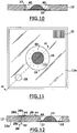
FIG. 11 is a bottom view of the cassette ofFIG. 10 showing the injection port of the cassette and an example of a tissue specimen in the cassette with the edges of the specimen positioned planar against the window by multiple bonds at locations around the tissue specimen; -
FIG. 12 is a cross-sectional view along line 12-12 ofFIG. 11 showing an example of a syringe needle inserting fluid into the cavity of the cassette through the injection port; -
FIG. 12A is a cross-sectional view along line 12-12 ofFIG. 11 showing an example of side injection ports to the cavity of the cassette; -
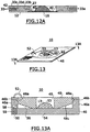
FIG. 13 is a perspective view of the cassette in accordance with another embodiment for sealing the upper member and base member of the cassette together; -
FIG. 13A is cross-sectional view alongline 13A-13A of the cassette ofFIG. 13 ; -
FIG. 13B is cross-sectional view alongline 13A-13A of the cassette ofFIG. 13 showing two injection ports; -
FIG. 13C is cross-sectional view alongline 13A-13A of the cassette ofFIG. 13 showing an example of a side injection port ofFIG. 1C ; -
FIG. 14 is a block diagram of a confocal microscope system with a cassette in accordance with the present invention; -
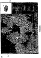
FIG. 15 is an illustration of a screen on the display of the system ofFIG. 14 during confocal imaging of a tissue specimen in the cassette; and -
FIG. 16 is an enlarged view illustrating the corrugations formed between a tissue specimen and the window of the cassette. - Referring to
FIGS. 1-3 , acassette 10 of the present invention is shown having abase member 12 and anupper member 14.Base member 12 has anaperture 18 and a rigid opticallytransparent window 16 situated inaperture 18. Theupper member 14 has anaperture 20 preferably substantially greater in size than theaperture 18 ofbase member 12. Base andupper members hinge 24 which allowscassette 10 to have an open state, as shown inFIG. 1 , and a closed state, as shown inFIG. 2 , whereupper member 14 coversbase member 12. Although preferably base andupper members hinge 24, they may, in the alternative, be separate and unattached to each other whencassette 10 is in an open state. - As best shown in
FIG. 3 , at thebottom surface 12a ofbase member 12, the base member has anannular shelf 22 in communication withaperture 18.Window 16 is inset onshelf 22, such thatbottom surface 12a of the base member is planar with thelower surface 16a ofwindow 16.Window 16 may be held by an adhesive, such as glue, uponshelf 22, or may be insert molded withbase member 12. In the alternative,window 16 may be attached tobottom surface 12a underneathaperture 18 withoutshelf 22, such as by an adhesive or glue along the part ofbottom surface 12a which interfaces withwindow 16, as shown inFIG. 4 . Thewindow 16 may be composed of a cut out sheet of thin glass or amorphous polyolefin, such as Zeonex plastic, or other optically homogeneous material through which optical imaging can be performed. Preferably,window 16 is of 152.4 micrometer (0.006 inch) thick Zeonex plastic film which is rigidly attached to thebase member 12 in either the configuration ofFIGS. 3 or 4 . The attachment ofwindow 16 incassette 10 should not be limited to that described herein. Any means for attaching an optical transparent window to form part ofbase member 12 may be used. The thickness of thewindow 16 depends on the working distance of the optical image system which will image the tissue specimen through the window. In a further alternative shown inFIG. 5 , thebase member 12 may itself be composed of an optically transmissive material, such as 1 millimeter thick Zeonex plastic, withoutaperture 18.Window 16 inFIG. 5 represents the part of thebase member 12 belowaperture 20 when thecassette 10 is in a closed state. - A pliable plastic membrane or film 26 (
FIGS. 1 and 1A ) is attached tobottom surface 14a ofupper member 12 acrossaperture 20.Membrane 26 does not extend to theouter edge 14b ofupper member 14, thereby leaving aregion 14c near the outer edge of the upper member. An adhesive, such as double-sided tape, may fixmembrane 26 toupper member 12 alongbottom surface 14a outsideregion 14c. Optionally,membrane 26 may be separate fromupper member 12, as shown inFIG. 1A , in which the membrane is held along one side byhinge 24. Themembrane 26 may be, for example, a thin layer of plastic, such as plastic wrap typically used for food preservation, and should be sufficiently transparent to provide viewing therethrough by a user or camera. -
Base member 12 further includes aninjection port 28, as best shown inFIG. 1B . Theinjection port 28 is defined by anopening 28a which extends from thelower surface 12a of thebase member 12 partially through the base member, achannel 28b which extends from theopening 28a to theupper surface 12b of thebase member 12, and a self-sealingmember 28c which is received in opening 28a from thebottom surface 12a of the base member. Between self-sealingmember 28c andchannel 28b is apassageway 28d in communication withchannel 28b. Self-sealingmember 28c may be composed of rubber, and may be similar to the self-sealing members used with medical vials for enabling a syringe needle to be inserted without loss of vial containment after removal of the syringe needle. An alternativeside injection port 33 from the side ofbase member 12 is shown inFIG. 1C .Injection port 33 has anopening 33a partially through the base member, achannel 33b which extend from opening 33a to the wall ofaperture 18, a self-sealingmember 33c which is received inopening 33a, and apassageway 33d between the self-sealingmember 33c andchannel 33b. As will be described later, a syringe needle may be inserted into theinjection port member passageway cassette 10 containing the tissue specimen, viachannel cassette 10 is in a closed state. Although only one injection port is illustrated inFIGS. 1, 1B and 1C , multiple ones of the injection ports may be provided incassette 10. - The base and
upper members Hinge 24 may also be made of plastic, or can be provided by a strip of adhesive material, such as tape, along the one side ofmembers Member cassette 10 are such thatwindow 16 has a diameter larger than the width of the tissue specimen to be located on the window. For example, the cassette may have anaperture 18 having a 2 cm diameter and a 3 mm depth towindow 16, and when closed the cassette may be 2.5 cm in length by 2.5 cm in width with a height of 7 mm. Thecassette 10 may be larger than these dimensions to accommodate larger tissue specimens. Apertures 18 and 20 are circular, but may be rectangular, or other shape. - In an open state, i.e., an
open cassette 10, a surgically exposedtissue specimen 13 is situated onwindow 16, as shown for example inFIGS. 1 and 1A . Typically, the tissue specimen is elliptical in shape with curved, sloping sides. With thetissue specimen 13 onwindow 16,upper member 14 is located over thebase member 12 to cover the base member, such thatmembrane 26 lies between the base member and upper member overaperture 18 of the base member. Thecassette 10 in this closed state, i.e., a closed cassette, is shown for example inFIG. 2 . In the example ofFIG. 1A ,FIG. 6 showsupper member 14 andmembrane 26 rotating along an arc defined byhinge 24 to provide a closed cassette, as indicated byarrows 30. - In a closed state, a hermetic seal is formed between the
upper member 14 andbase member 12 to define an enclosed cavity orcompartment 27 between themembrane 26 andwindow 16 containing tissue specimen 13 (FIGS. 2 and7 ). The seal may be provided by an adhesive, such as double-sided tape, along theregion 14c of upper member 14 (FIGS. 1 and 1A ). The seal may also be provided byregion 14c ofupper member 14 having a continuous raised ridge which may be received is a corresponding continuous groove on thetop surface 12b of thebase member 12, such that the raised ridge of the upper member snap fits in the groove of the base member. Other sealing means may alternatively be used, such as a gasket between the upper and base members, UV cure adhesive, sonic welding, or thermal welding. - In the closed cassette, the
tissue specimen 13 is observable through bothwindow 14, andmembrane 26 throughaperture 20 ofupper member 14. Althoughaperture 20 is preferably larger thanaperture 18, it may be the same size or smaller thanaperture 18 so long as when the cassette is closed both thetissue specimen 13 a gap or space 29 (FIG. 2 ) is viewable around theedges 13a of the tissue specimen throughaperture 20. Further, with thetissue specimen 13 sealed incavity 27, the injection port 28 (and/or injection port 33) enables fluids to be inserted or removed from the tissue specimen retained in thecavity 27. Alabel 31 with indicia identifying thetissue specimen 13 may be applied to thetop surface 32 of thecassette 10, or along thebottom surface 12a ofcassette 10, or both, such as shown inFIGS. 2 and11 . The indicia may represent a bar code or alphanumeric numerals identifying the tissue specimen, such as the patient name, date, physician, or other references to the surgical procedure. - Referring to
FIGS. 7-11 , the orientation of thetissue specimen 13 onwindow 16 in a closed cassette will now be described. If prior to closure ofcassette 10, thetissue specimen 13 onupper surface 16b ofwindow 16 inaperture 18 extends beyond thetop surface 12b ofbase member 12,membrane 26 compresses the tissue specimen, as shown inFIG. 7 . The top of thetissue specimen 13 may be scored prior to the closure of thecassette 10 to facilitate movement of theedges 13a of thetissue specimen 13 towardwindow 16. One or more scoring incisions along the top surface of the tissue may be needed when the specimen's edges are at a steep angle with respect to the surface ofwindow 16. Such incisions should not extend through the specimen, and may be in a cross-pattern or other pattern which relaxes tension of the tissue such that the tissue edges may be moved to flatten them againstwindow 16. - As shown in
FIG. 8 , a user, such as a physician or trained operator, using aprobe 34 manipulates one of theedges 13a of the tissue downwards against thewindow 16 under the tension ofmembrane 26, such that the edge is planar withupper surface 16b ofwindow 16. With theedge 13a held in that position, the user manipulates anotherprobe 36 against themembrane 26 ingap 29 until reachingwindow 16 at a location near the first probe which will hold theedge 13a in the desired position whenprobe 34 is removed, as shown inFIG. 9 . Theprobe 36 is then actuated by the user to conduct heat though thermal bond actuating means 38 to produce a bond (weld or joint) between themembrane 26 and thewindow 16 at a point or location 40 (FIG. 10 ), thereby retaining theedge 13a of the specimen in the desired planar orientation againstwindow 16. Thermal bond actuating means 38 may be similar to a soldering iron operating at a low temperature to weld the material of the plastic membrane and window together without affecting the integrity of the cavity. Other bond actuating means may also be used, such as sonic welding. If needed, more than one bond atdifferent locations 40 ingap 29 may be used to retainedge 14a. This is repeated around thetissue specimen 13 until all of theedges 13a are held in a planar orientation against thewindow 16 bymultiple bonds 40 betweenmembrane 26 andwindow 16.FIGS. 10 and 11 showmultiple bonds 40 retaining thetissue specimen 13 is the desired planar orientation.Probes membrane 26 during this procedure. In this manner,tissue specimen 13 is oriented in aclosed cassette 10 such that theedges 13a of the tissue specimen are positioned planar against thewindow 16 and are retained in that position by bonds formed between themembrane 26 andwindow 16 at multiple points orlocations 40 around the tissue specimen. - In the alternative to thermally or sonically formed bonds, a contact adhesive may be applied to the
upper surface 16a ofwindow 16 or the surface ofmembrane 26 facingwindow 16, or both, prior to placement of the tissue specimen in the cassette, such thatprobe 36 by contactingmembrane 26 towindow 16 adhesively bonds them to each other at apoint 40. Further, the contact adhesive may be a UV light cure adhesive, such that after the bonds are formed they may be exposed to UV light to harden them. - Referring to
FIG. 12 , a syringe (not shown) with aneedle 42 may be inserted intoinjection port 28 through self-sealingmember 28c to force fluid intocavity 27 throughpassage 28d andchannel 28b. Since multiple bonds do not sealtissue specimen 13 withincavity 27, the fluid freely flows to thetissue specimen 13, thereby immersing the tissue specimen in fluid, as shown byarrows 44. The fluid may represent an optical index matching fluid to facilitate imaging of the specimen by an optical imaging microscope. Similarly, the fluid may be withdrawn by the use of a syringe withneedle 42 to suction the fluid fromcavity 27. The self-sealingmember 28c allows the insertion of the needle without compromising the integrity of thecavity 27. Thus, the tissue specimen is retained in the cassette in the desired orientation, while being permeable to fluids inserted through theinjection port 28. The fluid inserted flows between thetissue specimen 13 andwindow 16 due to the elasticity of themembrane 26 and the pressure of the fluid. - For the
side injection port 33 ofFIG. 1B ,FIG. 12A shows theneedle 42 inserted intoinjection port 33 through self-sealingmember 33c to insert fluid to, or withdraw fluid from,cavity 27 throughpassage 33d andchannel 33b.FIG. 12A also shows anotherside injection port 33a identical toinjection port 33, but orientedopposite injection port 33 inbase member 12, such that the cassette has twoinjection ports cavity 27 by simultaneously inserting a fluid throughport 33 and removing the fluid throughport 33a, or vise versa. Thesecond injection port 33a may also serve as a backup port if thefirst injection port 33 fails to function. - Referring to
FIGS. 13 and 13A , another embodiment is shown for sealing the upper and base members ofcassette 10 together. In this embodiment, the base and upper members ofcassette 10 are denoted as 46 and 48, respectively, and the base member ofFIG. 5 is shown.Base member 46 has anannular wall 46a which extends about its periphery into which theupper member 48 can be received. Theupper member 48 has anaperture 49 and an annular ridge ortongue 48a which extends along its outer edge.Upper member 48 is insertable into thebase member 46 such thatridge 48a fits into anannular groove 46b ofbase member 46 along the inside ofwall 46a, thereby sealing theupper member 48 to thelower member 46 to define anenclosed cavity 56 between themembrane 53 and thebase member 46. The compression of theedges 13a of the tissue specimen orients such edges planar against awindow 54, which is defined by the part of the opticallytransmissive base member 46 belowaperture 49 ofupper member 48.Upper member 48 is attached tobase member 46 by aloop member 52, which may be composed of plastic.Aperture 49 may be sized sufficiently larger that thetissue specimen 13 to enable multiple bonds to be made betweenmembrane 53 andwindow 54 to hold the edges positioned planar to the window, such as described earlier.Membrane 53 is similar tomembrane 26, andinjection port 50 is similar toinjection port 28 with a self-sealingmember 59 and achannel 58 throughwall 46a to enable fluids to be insertable and removable from thetissue specimen 13 incavity 56.Upper member 48 may have circular or disc-like shape with a circular, curved lower surface 48b. - Referring to
FIG. 13B , in the embodiment shown inFIG. 13 , asecond injection port 50a may be provided from the top surface ofbase member 46 in addition to, or instead of,injection port 50. Likeinjection port 50,injection port 50 has a self-sealingmember 59a and achannel 58a throughwall 46a to enable fluids, via a syringe needle, to be insertable and removable from thetissue specimen 13 incavity 56. The twoports channels base member 46. By providing acassette 10 with two injection ports, fluid can be simultaneously inserted through one port and removed through the other port to enable a fluid flow throughcavity 56. Although only one or two ports are shown, additional number of ports may be similarly provided at different location in the base member. A variation of theinjection port FIG. 13C in which aside injection port 50b is provided through the side ofbase member 46. Likeinjection ports injection port 50b has a self-sealingmember 59b and a channel 58b throughwall 46a to enable fluids, via a syringe needle, to be insertable and removable from thetissue specimen 13 incavity 56. Multiple ones ofside injection port 50b, such as two, may be provided at opposite sides of thebase member 46. - Referring to
FIG. 14 , aconfocal imaging system 60 having thecassette 10 is shown.Confocal imaging system 60 includes acomputer control system 62 having aconfocal imaging head 64 with a liquidimmersion objective lens 64a, and adisplay 66 anduser interface 68 coupled to controlsystem 62. Theconfocal imaging head 64 andcontrol system 62 provides confocal microscopic images of optically sectioned tissue on thedisplay 66 as described, for example, inU.S. Patent No. 5,788,639 , or inpublished International Patent Application WO 96/21938 confocal imaging head 64,control system 62,display 66, anduser interface 68 may represent a confocal microscope, such as the "VivaScope" manufactured by Lucid, Inc. of Henrietta, New York. A z-actuator 70 can move the confocal imaging head 64 (or alternately, onlyobjective lens 64a) in a z direction, via signals fromcontrol system 62, to control the depth of imaging in tissue, i.e., the distance ofobjective lens 64a towindow 16 ofcassette 10. - The
confocal imaging system 60 further includes anx-y stage 72 which supportscassette 10 and presents thewindow 16 of the cassette to a liquidimmersion objective lens 64a of theconfocal imaging head 64.Stage 72 has actuators (not shown) which can move thecassette 10 in x,y orthogonal directions in response to signals fromcontrol system 62.User interface 68 may represent a keyboard, mouse, joystick, or combinations thereof, which enable a user, viacontrol system 62, to control the z-actuator 70 andx-y stage 72 such that different parts of the tissue specimen may be imaged by theconfocal imaging head 64. Prior to locating the cassette instage 72, a fluid which is matched to the optical index of theimmersion objective lens 64a is inserted into the cavity of thecassette 10 via theinjection port optical coupling fluid 71 may be placed betweenlens 64a andwindow 16 ofcassette 10 to optically couple thelens 64a towindow 16. The fluid 71 may have the same optical index as the fluid inserted in the cavity ofcassette 10. Thecassette 10 may that than shown inFIGS. 11 or13 . - An
optional camera 74 in theconfocal imaging system 60 is provided to capture images of the tissue specimen through alens 74a directed toaperture 20 inupper member 14 of thecassette 10.Camera 74 may be a digital camera which captures still images, or may be a video camera. The control system may also send signals to thecamera 74 to control its operation, such as enabling the camera to capture an image or focusing the camera. Signals representing captured images fromcamera 74 are received by thecontrol system 62. - On
display 66 thecontrol system 62 visualizes images of microscopic sections of the tissue specimen fromconfocal imaging head 64 and macroscopic images fromcamera 74.FIG. 15 shown an example of a screen (denoted as 75) ofdisplay 66 during confocal imaging, whereimage 76 represents a macroscopic image of a tissue specimen incassette 10 fromcamera 74, andimage 78 represents an optical section of the tissue specimen imaged throughconfocal imaging head 64.Image 76 may be maintained on thescreen 75 during optical sectioning to guide the user as to the location ofmicroscopic section 78 with respect to the tissue specimen. For example, abox 77 may indicate the relative location of themicroscopic image 78 with respect to themacroscopic image 76. Thex-y stage 72 is positioned with respect tocamera lens 74a such that a marker, such as a cross-hair, may be overlaid bycontrol system 62 onmacroscopic image 76 showing the relative location of theconfocal imaging head 64 with respect to the tissue specimen. Since the edges of the tissue specimen are planar againstwindow 16 ofcassette 10, optical sections imaged ondisplay 66 from along the edges of the tissue specimen can provide information determining whether a tumor is fully contained in the tissue specimen for Mohs surgery. If desired, images of optical sections from different parts of the tissue specimen may be scanned automatically by thecontrol system 62 by controlling the movement of x,y stage 72. The scanned images of optical sections are electronically combined in memory of thecontrol system 62 to provide an optical section having a larger field of view to the user. If imaging by another confocal imaging head is desired, the fluid can be replaced with a different optical index matching fluid, viainjection port 28 of the cassette. - Although a
confocal imaging head 64 is described herein, other optical imaging techniques may also be used inhead 64, such as optical coherence tomography, such as described in Schmitt et al., "Optical characterization of disease tissues using low-coherence interferometry," Proc. of SPIE, Volume 1889 (1993), or a two-photon laser microscope, as described inU.S. Patent No. 5,034,613 . - After imaging of the tissue specimen is complete, the tissue specimen can be removed from
stage 72 and archived incassette 10. To preserve the tissue specimen, a preservative fluid, such as formalin, may be inserted in the cavity of the cassette, viainjection port 28, after any fluid in the cavity is removed. The entire cassette with the tissue specimen from Mohs surgery can thus be stored intact withindicia 31 on the cassette referencing the procedure. Optical sectioning of tissue specimens can facilitate their archiving since intact specimens may require less storage space than traditional slides, and can easily be labeled withindicia 31 on the cassette. - The particular immersion fluid inserted through an injection port into the cavity of the
cassette 10 containing thetissue specimen 13 may be selected as follows to enhance imaging. Surface corrugations at the interface between thetissue specimen 13 and thewindow 16 are filled with the immersion fluid, which produces optical corrugations in the wavefront of the beam focused into the specimen. These corrugations reduce the fidelity of the images. The effect of the corrugations can be reduced by matching the refractive index of the immersion liquid with the tissue. As shown inFIG. 16 , the corrugations due to the surface texture of thespecimen 13 creates corrugations having a depth (h) (from the apex of the corrugation peaks to the bottom of the valleys of the corrugations) which may be approximately 200 microns in length. The index of refraction of the tissue is nT, while the index of refraction of the immersion fluid, which fills the corrugations providing the surface texture of thespecimen 13, have an index nI. The beam is focused at a focus f in the section to be imaged. The wavefront which may be spherical, can be distorted due to an optical path difference ϕ imprinted on the wavefront which converges to the focus F. This path difference is a function of the product of the corrugation height h and the difference between nT and nI. The use of the index matching fluid reduces the optical path difference so that the imprint is minimized. The optical path difference ϕ is shown enlarged at 80 inFIG. 16 . This optical path difference may also be viewed as the wavefront which is propagating to the focus F. This wavefront may be spherical and part of a sphere as shown at 82 prior to passing through corrugations at the surface of thespecimen 13. The optical path distortion after transmission through the tissue surface is approximated by the relation ϕ = h (nT - nI), where h is the mechanical depth of surface texture. In order to correct for the distortion of the beam wavefront (which may be a spherical wavefront) by virtue of the variation in index of refraction presented by corrugations, it is desirable that the difference in index of theimmersion liquid 84 and the average index of refraction of the tissue multiplied by the corrugation height h that is the optical path distance between the hills and valleys of the corrugation), not exceed a quarter wavelength of the laser beam which is used for imaging by theimaging system 62. Thus, theimmersion medium 84 is selected for the tissue type which is placed in the cassette and substantially corrects for optical distortion due to the surface texture of the tissue specimen. - From the foregoing description, it will be apparent that there has been provided a cassette for facilitating optical sectioning of a retained tissue specimen. Variations and modifications in the herein described cassette and method in accordance with the invention will undoubtedly suggest themselves to those skilled in the art. Accordingly, the foregoing description should be taken as illustrative and not in a limiting sense.
Claims (22)
- A cassette (10) for enabling optical imaging of a surgically exposed tissue specimen (13) having edges (13a) by an optical imaging microscope comprising:a base member (12; 46) having an optically transparent window (16; 54);an upper member (14; 48) comprising an aperture (20);a pliable plastic membrane (26; 53) attached to the bottom surface of said upper member (14; 48) across said aperture (20) and facing said base member (12; 46), said membrane being locatable over a substantial portion of said base member (12; 46) including said window (16; 54); andwherein, when a tissue specimen (13) is located on said window (16; 54), said upper member (14; 48) locates said membrane (26; 53) over said base member (12; 46) to produce an enclosed cavity (27) between said membrane (26; 53) and said window (16; 54) having said tissue specimen (13) therein; andan adhesive applied to the lower surface of the membrane (12, 46) or the upper surface of the window (16, 54) facing the membrane (26, 53), prior to placement of the tissue specimen in the cassette, such that contact of the membrane (12, 46) and window (16, 54) by a probe forms an adhesive bond.
- The cassette (10) according to Clam 1, wherein said tissue specimen (13) is viewable through said window (16; 64) when the tissue specimen (13) is located in the enclosed cavity (27) between the membrane (26; 53) and the window (16; 54).
- The cassette (10) according to Claim 1, wherein said tissue specimen (13) is positionable through said membrane (26; 53), when the tissue specimen (13) is located in the enclosed cavity (27).
- The cassette (10) according to Claim 1, wherein said tissue specimen (13) has at least one edge (13a) positionable through said membrane (26; 53) planar against said window (16; 54) when the tissue specimen (13) is located in the enclosed cavity (27), and said cassette (10) further comprises at least one bond formed between said membrane (26; 53) and said window (16; 54) to retain said edge (13a) of the tissue specimen (13) planar against said window (16; 54).
- The cassette (10) according to Claim 1, wherein said base member (12; 46) further comprises an upper surface (12b) facing said upper member (14; 48) and an aperture (18) extending through said upper surface (12b) within which said window (16; 54) is located.
- The cassette (10) according to Claim 1, wherein said base member (12; 46) is composed of an optically transparent material providing a window (16; 54) upon which the specimen (13) is situated.
- The cassette (10) according to Claim 1, wherein said base member (12; 46) further comprises at least one injection port (28; 33; 50; 50a; 50b) through which liquids are injectable and removable from said cavity (27).
- The cassette (10) according to Claim 7, wherein said injection port (28; 33; 50; 50a; 50b) comprises an opening (28a; 33a) having a self-sealing member (28c; 33c; 59, 59a, 59b) and a channel (28b; 33b; 58, 58a, 58b) from the opening (28a; 33a) into the cavity (27).
- The cassette (10) according to Claim 7, wherein said injection port (28; 33; 50; 50a; 50b) is located through the bottom or side of said base member (12, 46).
- The cassette (10) according to Claim 1, further comprising means (24; 52) for coupling said upper and base members (14, 48 and 12, 46) to each other to enable said upper and base members (14, 48 and 12, 46) to be positionable in an open state to allow placement of a tissue specimen (13) upon the window (16; 54) of said base member (12; 46), and then in a closed state wherein said upper member (14; 48) covers said base member (12; 46) to form the cavity (27) between said membrane (26; 53) and said window (16; 54) retaining said tissue specimen (13) therein.
- The cassette (10) according to Claim 8, wherein said means further couples one side of said membrane (26; 53) to enable said membrane (26; 53) to be maintained between said upper and base members 14; 48 and 12; 46).
- The cassette (10) according to Claim 1, wherein said window (16; 54) is rigid.
- The cassette (10) according to Claim 1, wherein said upper member (14; 48) has a surface (14a) and said aperture (20) extending through said surface (14a) and said membrane (26; 53) has an outer edge (14b) which may be attached to said surface (14a) of said upper membrane (14; 48).
- The cassette (10) according to Claim 1, wherein said membrane (26; 53) is a thin layer of plastic.
- The cassette (10) according to Claim 1, further comprising means for sealing said base member (12; 46) and said upper member (14; 48) together to define the enclosed cavity (27) therein.
- The cassette (10) according to Claim 1, further comprising means for sealingly engaging the upper member (14; 48) to the lower member (12; 48) to form a hermetic seal to define the cavity (27) between said membrane (26; 53) and said window (16; 54).
- The cassette (10) according to Claim 1, wherein said upper member (14; 48) has a continuous outer edge, and said base member (12; 46) has a continuous side wall (46a) into which said upper member (14; 48) Is received, and said cassette (10) further comprises means (46b; 48a) provided by said upper and base members (14; 48 and 12, 46) to couple said outer edge of said upper member (14; 48) along the side wall (46a) of the base member (12; 46) to form a cavity (27) capable of retaining a tissue specimen (13) between the membrane (26; 53) and the window (16; 54).
- The cassette (10) according to Claim 1, further comprising a label (31) having indicia.
- A method for using a cassette (10) for preparing a tissue specimen (13) for examination by a confocal microscope (60) or other optical imaging microscope comprising the steps of:applying an adhesive to the lower surface of the membrane (12, 46) or the upper surface of the window (16, 54) facing the membrane (26, 53), prior to placement of the tissue specimen in the cassette, such that contact of the membrane (12, 46) and window (16, 54) by a probe forms an adhesive bond.locating a tissue specimen (13) on an optically transparent window (16; 54) of a base member (12; 46);placing an upper member (14; 48) comprising an aperture (20) and a pliable optically transparent plastic membrane (26; 53) attached to the bottom surface of said upper member (14; 48) across said aperture (20) facing said base member (12; 46) over at least a substantial portion of said base member (12; 46) including said window (16; 54).sealingly engaging the membrane (26, 53) to the base member (12; 46) to produce a cavity (27) between said membrane (26; 53) and said window (16; 54).
- The method according to Claim 19, further comprising the steps of:positioning edges (13a) of the tissue specimen (13) against the window (16; 54); andfixing the location of the edges (13a) positioned against the window (16; 54) by connecting the membrane (26; 53) to the window (16; 54) at multiple points.
- The method according to Claim 19, further comprising the step of:inserting a fluid (44) into said cavity through said base member (12; 46) through an injection port in the base member (12; 46).
- The method according to Claim 19, further comprising the step of:imaging said tissue specimen (13) through said window (16; 54).
Applications Claiming Priority (3)
| Application Number | Priority Date | Filing Date | Title |
|---|---|---|---|
| US12053499P | 1999-02-17 | 1999-02-17 | |
| US120534P | 1999-02-17 | ||
| PCT/US2000/004070 WO2000049392A1 (en) | 1999-02-17 | 2000-02-17 | Cassette for facilitating optical sectioning of a retained tissue specimen |
Publications (3)
| Publication Number | Publication Date |
|---|---|
| EP1169630A1 EP1169630A1 (en) | 2002-01-09 |
| EP1169630A4 EP1169630A4 (en) | 2007-10-24 |
| EP1169630B1 true EP1169630B1 (en) | 2017-02-01 |
Family
ID=22390917
Family Applications (1)
| Application Number | Title | Priority Date | Filing Date |
|---|---|---|---|
| EP00913499.0A Expired - Lifetime EP1169630B1 (en) | 1999-02-17 | 2000-02-17 | Cassette for facilitating optical sectioning of a retained tissue specimen |
Country Status (5)
| Country | Link |
|---|---|
| US (4) | US6411434B1 (en) |
| EP (1) | EP1169630B1 (en) |
| JP (1) | JP4564664B2 (en) |
| AU (1) | AU3493800A (en) |
| WO (1) | WO2000049392A1 (en) |
Families Citing this family (71)
| Publication number | Priority date | Publication date | Assignee | Title |
|---|---|---|---|---|
| EP1121052B1 (en) * | 1998-09-14 | 2018-07-25 | Lucid, Inc. | Imaging of surgical biopsies |
| US7227630B1 (en) | 1998-09-14 | 2007-06-05 | Lucid, Inc. | Imaging of surgical biopsies |
| US6330106B1 (en) | 1999-02-17 | 2001-12-11 | Lucid, Inc. | Tissue specimen holder |
| EP1169630B1 (en) | 1999-02-17 | 2017-02-01 | Lucid, Inc. | Cassette for facilitating optical sectioning of a retained tissue specimen |
| US7194118B1 (en) | 2000-11-10 | 2007-03-20 | Lucid, Inc. | System for optically sectioning and mapping surgically excised tissue |
| US6693767B1 (en) * | 2001-07-31 | 2004-02-17 | Western Digital Technologies, Inc. | Disk drive having a head disk assembly enclosure including an integrated hinge |
| US20070255169A1 (en) * | 2001-11-19 | 2007-11-01 | Dune Medical Devices Ltd. | Clean margin assessment tool |
| US20040133112A1 (en) * | 2002-03-08 | 2004-07-08 | Milind Rajadhyaksha | System and method for macroscopic and confocal imaging of tissue |
| JP4105164B2 (en) | 2002-09-26 | 2008-06-25 | バイオパス・オートメーション・エル・エル・シー | Apparatus and method for automating the handling and embedding of tissue specimens |
| EP1545775B1 (en) | 2002-09-26 | 2010-06-16 | BioPath Automation, L.L.C. | Cassette and embedding assembly, staging devices, and methods for handling tissue samples |
| US7179424B2 (en) * | 2002-09-26 | 2007-02-20 | Biopath Automation, L.L.C. | Cassette for handling and holding tissue samples during processing, embedding and microtome procedures, and methods therefor |
| DE10250247B4 (en) * | 2002-10-28 | 2006-06-01 | Leica Microsystems Cms Gmbh | Sample carrier for microscopy and method for preparing a sample carrier |
| WO2005078503A1 (en) * | 2004-02-16 | 2005-08-25 | Olympus Corporation | Immersion object lens, immersion medium retaining mechanism and production method therefor |
| US7215431B2 (en) * | 2004-03-04 | 2007-05-08 | Therma-Wave, Inc. | Systems and methods for immersion metrology |
| JP2008508533A (en) * | 2004-08-05 | 2008-03-21 | イェーペーカー インストゥルメンツ アクチエンゲゼルシャフト | Inspection sample container |
| JP4585329B2 (en) * | 2005-02-10 | 2010-11-24 | 東芝機械株式会社 | Thin slice preparation method and thin slice specimen |
| US20060227108A1 (en) * | 2005-03-31 | 2006-10-12 | Ikey, Ltd. | Computer mouse for harsh environments and method of fabrication |
| US20070116612A1 (en) * | 2005-11-02 | 2007-05-24 | Biopath Automation, L.L.C. | Prefix tissue cassette |
| US7864996B2 (en) | 2006-02-17 | 2011-01-04 | Lucid, Inc. | System for macroscopic and confocal imaging of tissue |
| US8260401B2 (en) * | 2006-07-26 | 2012-09-04 | University Of Rochester | Non-invasive in-vivo imaging of mechanoreceptors in skin using confocal microscopy |
| CN101583315A (en) * | 2006-12-12 | 2009-11-18 | 比欧帕斯自动化公司 | Biopsy support with sectionable resilient cellular material |
| EP2313754B1 (en) * | 2008-07-18 | 2017-11-01 | Leica Biosystems Newcastle Limited | Method for preparing cell standard |
| US20100081190A1 (en) * | 2008-09-29 | 2010-04-01 | Searete Llc, A Limited Liability Corporation Of The State Of Delaware | Histological facilitation systems and methods |
| US20100081923A1 (en) * | 2008-09-29 | 2010-04-01 | Searete Llc, A Limited Liability Corporation Of The State Of Delaware | Histological facilitation systems and methods |
| US20100081924A1 (en) * | 2008-09-29 | 2010-04-01 | Searete Llc, A Limited Liability Corporation Of The State Of Delaware | Histological facilitation systems and methods |
| US20100081925A1 (en) * | 2008-09-29 | 2010-04-01 | Searete Llc, A Limited Liability Corporation Of The State Of Delaware | Histological facilitation systems and methods |
| US20100081919A1 (en) * | 2008-09-29 | 2010-04-01 | Searete Llc, A Limited Liability Corporation Of The State Of Delaware | Histological facilitation systems and methods |
| US9791386B2 (en) | 2009-01-20 | 2017-10-17 | Spectro Scientific, Inc. | Integrated, portable sample analysis system and method |
| US8384895B2 (en) | 2009-01-20 | 2013-02-26 | Spectro, Inc. | Spectrometer flip top sample head |
| BRPI1006958B1 (en) | 2009-01-22 | 2019-11-19 | Biopath Automation Llc | histological tissue specimen support and guidance devices and methods of preparing one or more elongated biopsy tissue samples for histological examination |
| CN102713720B (en) | 2009-10-28 | 2016-05-11 | 阿兰蒂克微科学股份有限公司 | Microscopic imaging device and micro imaging method |
| US9075225B2 (en) | 2009-10-28 | 2015-07-07 | Alentic Microscience Inc. | Microscopy imaging |
| US9310450B2 (en) | 2010-02-01 | 2016-04-12 | Clear-Cut Medical Ltd. | Margin assessment of ex-vivo sample |
| US9795340B2 (en) * | 2010-12-13 | 2017-10-24 | National Taiwan University | Vacuum-pump sucker |
| US8661878B2 (en) | 2011-01-18 | 2014-03-04 | Spectro, Inc. | Kinematic viscometer and method |
| CN202281862U (en) * | 2011-08-31 | 2012-06-20 | 清华大学 | Stereomicroscope |
| EP2615443B1 (en) * | 2012-01-16 | 2022-06-01 | MAVIG GmbH | Method for preparing a tissue sample |
| ES2878548T3 (en) * | 2012-02-26 | 2021-11-19 | Caliber Imaging & Diagnostics Inc | Tissue specimen stage for an optical sectioning microscope |
| WO2013142459A2 (en) * | 2012-03-21 | 2013-09-26 | Clear-Cut Medical Ltd. | Mri system for margin assessment of ex-vivo sample |
| EP2883031B1 (en) * | 2012-08-13 | 2020-04-22 | Memorial Sloan-Kettering Cancer Center | Devices applicable to tissue(s) which facilitates confocal microscopy, optical microscopy, spectroscopy and/or imaging |
| US8741232B2 (en) * | 2012-09-05 | 2014-06-03 | Faxitron Bioptics, Llc | Specimen imaging device and methods for use thereof |
| US9677869B2 (en) | 2012-12-05 | 2017-06-13 | Perimeter Medical Imaging, Inc. | System and method for generating a wide-field OCT image of a portion of a sample |
| US10502666B2 (en) | 2013-02-06 | 2019-12-10 | Alentic Microscience Inc. | Sample processing improvements for quantitative microscopy |
| CN105324698B (en) * | 2013-05-01 | 2019-07-02 | 生物辐射实验室股份有限公司 | Adjustable digital microscope is shown |
| EP3014330B1 (en) * | 2013-06-26 | 2024-01-03 | Alentic Microscience Inc. | Sample processing improvements for microscopy |
| JP6446780B2 (en) * | 2013-12-20 | 2019-01-09 | 東洋紡株式会社 | Speculum plate, semi-finished speculum plate, and method of manufacturing speculum plate |
| GB2523774B (en) * | 2014-03-04 | 2019-07-17 | Calamat Ltd | Microscope slide |
| CN106687036B (en) * | 2014-05-05 | 2021-06-08 | 凯利博成像和诊断公司 | System and method for mapping the location of a captured confocal image of a lesion in skin tissue |
| US11513038B2 (en) | 2014-06-30 | 2022-11-29 | Koninklijke Philips N.V. | Sample holder for biological samples |
| WO2016084309A1 (en) * | 2014-11-25 | 2016-06-02 | パナソニックIpマネジメント株式会社 | Electronic prepared slide, solid state imaging element, electronic prepared slide assembly set, and electronic prepared slide assembly method |
| KR101689879B1 (en) | 2015-08-31 | 2016-12-26 | 재단법인 의약바이오컨버젼스연구단 | Window apparatus for in vivo microscopic imaging of mammary tissue and method for obtaining image using the same |
| KR101743283B1 (en) * | 2015-08-31 | 2017-06-02 | 재단법인 의약바이오컨버젼스연구단 | Lung window apparatus based on micro-suction for in vivo microscopic imaging of lung tissue and method for obtaining image using the same |
| WO2017053825A1 (en) | 2015-09-25 | 2017-03-30 | The Regents Of The University Of Michigan | Biopsy device for coherent raman imaging |
| US10514532B1 (en) | 2015-09-27 | 2019-12-24 | Caliber Imaging & Diagnostics, Inc. | Confocal microscope having a positionable imaging head mounted on a boom stand |
| JP6550348B2 (en) * | 2016-04-07 | 2019-07-24 | 一般社団法人白亜会 | Biopsy material digital imaging device |
| EP3446093B1 (en) * | 2016-04-21 | 2021-02-24 | President and Fellows of Harvard College | Gridtape for fast nanoscale imaging |
| EP3538942B1 (en) | 2016-11-12 | 2023-08-23 | Caliber Imaging & Diagnostics, Inc. | Confocal microscope with positionable imaging head |
| KR101940399B1 (en) * | 2017-04-25 | 2019-01-18 | 가톨릭대학교 산학협력단 | Medical inspection slide unit |
| WO2018204712A1 (en) * | 2017-05-04 | 2018-11-08 | The Regents Of The University Of California | Waveguide-based side-illumination technique for muse microscopy and associated histology cassettes |
| US11598945B2 (en) * | 2017-07-11 | 2023-03-07 | Carl Zeiss Microscopy Gmbh | Adapter for use with a sample holder, and method for arranging a sample in a detection beam path of a microscope |
| WO2019014767A1 (en) | 2017-07-18 | 2019-01-24 | Perimeter Medical Imaging, Inc. | Sample container for stabilizing and aligning excised biological tissue samples for ex vivo analysis |
| JP7092294B2 (en) | 2017-12-13 | 2022-06-28 | 学校法人東海大学 | A material for coating a biological tissue made of an ultra-thin film, and a biological tissue coated with the material. |
| WO2019118936A2 (en) | 2017-12-14 | 2019-06-20 | Essenlix Corporation | Devices, systems, and methods for monitoring hair |
| WO2019165480A1 (en) | 2018-02-26 | 2019-08-29 | Caliber Imaging & Diagnostics, Inc. | System and method for macroscopic and microscopic imaging ex-vivo tissue |
| US10527528B2 (en) * | 2018-05-22 | 2020-01-07 | Applikate Technologies Llc | Tissue chamber |
| DE102018221670A1 (en) * | 2018-12-13 | 2020-06-18 | Karlsruher Institut für Technologie | Device and method for the optical characterization or processing of an object |
| CN114423491A (en) * | 2019-07-17 | 2022-04-29 | Ue生命科学有限公司 | System and method for measuring tissue parameters by using capacitive touch sensors |
| DE102019120201B3 (en) * | 2019-07-25 | 2020-06-04 | Leica Biosystems Nussloch Gmbh | Arrangement with object plate and transparent marking frame |
| CN110646274B (en) * | 2019-09-18 | 2022-04-22 | 山东省立医院 | Disposable intraoperative frozen pathological tissue sampling and collecting device and application thereof |
| JP7365887B2 (en) * | 2019-12-17 | 2023-10-20 | 浜松ホトニクス株式会社 | Biological sample holding container and biological sample holding method |
| CA3174596A1 (en) * | 2020-03-06 | 2021-09-10 | Alentic Microscience Inc. | Portable imaging device |
Citations (1)
| Publication number | Priority date | Publication date | Assignee | Title |
|---|---|---|---|---|
| US3990850A (en) * | 1976-01-06 | 1976-11-09 | Akzona Incorporated | Diagnostic test card |
Family Cites Families (43)
| Publication number | Priority date | Publication date | Assignee | Title |
|---|---|---|---|---|
| US1002910A (en) * | 1911-01-21 | 1911-09-12 | Foote Mineral Co | Display-mount. |
| US2942520A (en) * | 1955-12-20 | 1960-06-28 | George G Rose | Tissue culture device |
| US3031924A (en) * | 1959-03-12 | 1962-05-01 | James C Lamal | Observation slide |
| US3510194A (en) * | 1965-08-09 | 1970-05-05 | Robert F Connelly | Particle count membrane filter mount |
| US3532412A (en) * | 1969-01-17 | 1970-10-06 | Ibm | Package for and method of packaging pathology specimens |
| US3556633A (en) | 1969-01-17 | 1971-01-19 | Winifred Liu Mutschmann | Specimen carrying slide with runoff trough |
| US3551023A (en) * | 1969-01-17 | 1970-12-29 | Ibm | Pathology specimen processing method and article |
| US3736042A (en) * | 1971-05-05 | 1973-05-29 | Clinical Sciences Inc | Microscope slide assembly |
| US3879106A (en) * | 1973-04-11 | 1975-04-22 | Pelam Inc | Microscope slide cover slip |
| DE2655041C2 (en) | 1976-12-04 | 1982-04-15 | Fa. Carl Zeiss, 7920 Heidenheim | Immersion objective for use with several optically different immersion media |
| US4565783A (en) * | 1981-01-27 | 1986-01-21 | Minnesota Mining And Manufacturing Company | Dry culture media |
| US4545831A (en) * | 1982-09-13 | 1985-10-08 | The Mount Sinai School Of Medicine | Method for transferring a thin tissue section |
| SE455736B (en) | 1984-03-15 | 1988-08-01 | Sarastro Ab | PROCEDURE KIT AND MICROPHOTOMETRATION AND ADDITIONAL IMAGE COMPOSITION |
| US4752347A (en) * | 1986-10-03 | 1988-06-21 | Rada David C | Apparatus for preparing tissue sections |
| FR2626383B1 (en) | 1988-01-27 | 1991-10-25 | Commissariat Energie Atomique | EXTENDED FIELD SCAN AND DEPTH CONFOCAL OPTICAL MICROSCOPY AND DEVICES FOR CARRYING OUT THE METHOD |
| US4974952A (en) | 1988-03-31 | 1990-12-04 | Focht Daniel C | Live cell chamber for microscopes |
| US5002735A (en) * | 1988-07-12 | 1991-03-26 | Mark T. Alberhasky | Tissue analysis device |
| EP1245987B1 (en) | 1988-07-13 | 2008-01-23 | Optiscan Pty Ltd | Scanning confocal microscope |
| JPH0641948B2 (en) * | 1988-09-21 | 1994-06-01 | フクビ化学工業株式会社 | Observation plate and method of manufacturing the same |
| JPH0378720A (en) | 1989-08-22 | 1991-04-03 | Nikon Corp | Confocal laser scanning microscope |
| US5034613A (en) | 1989-11-14 | 1991-07-23 | Cornell Research Foundation, Inc. | Two-photon laser microscopy |
| US5719700A (en) | 1991-10-11 | 1998-02-17 | L'oreal | Apparatus for in vivo observation of the microscopic structure of the skin or of a similar tissue |
| US5889881A (en) | 1992-10-14 | 1999-03-30 | Oncometrics Imaging Corp. | Method and apparatus for automatically detecting malignancy-associated changes |
| GB2273994A (en) | 1992-12-18 | 1994-07-06 | Morphometrix Inc | Process microscopy system |
| US5364790A (en) * | 1993-02-16 | 1994-11-15 | The Perkin-Elmer Corporation | In situ PCR amplification system |
| US5383472A (en) * | 1993-07-22 | 1995-01-24 | Devlin; Mark T. | Method and apparatus for handling of biopsy tissue specimen |
| PT720508E (en) | 1993-09-22 | 2000-09-29 | Pierce Chemical Co | DEVICE FOR DIALISING SAMPLES |
| DE4423935C2 (en) * | 1994-07-07 | 1998-02-05 | Deutsche Forsch Luft Raumfahrt | Cell for microscopic or macroscopic observation of a biological sample |
| US5880880A (en) | 1995-01-13 | 1999-03-09 | The General Hospital Corp. | Three-dimensional scanning confocal laser microscope |
| WO1996021938A1 (en) | 1995-01-13 | 1996-07-18 | The General Hospital Corporation | Video-rate confocal scanning laser microscope |
| US5788639A (en) | 1995-07-13 | 1998-08-04 | Lucid Technologies, Inc. | Confocal imaging through thick dermal tissue |
| US5939251A (en) * | 1996-07-12 | 1999-08-17 | Hu; Min | Apparatus and method for simplifying the processes in creating a sealed space on slides to conduct molecular biological reactions therein |
| US5870223A (en) | 1996-07-22 | 1999-02-09 | Nikon Corporation | Microscope system for liquid immersion observation |
| US6272235B1 (en) | 1997-03-03 | 2001-08-07 | Bacus Research Laboratories, Inc. | Method and apparatus for creating a virtual microscope slide |
| US5836877A (en) | 1997-02-24 | 1998-11-17 | Lucid Inc | System for facilitating pathological examination of a lesion in tissue |
| US5812312A (en) * | 1997-09-04 | 1998-09-22 | Lorincz; Andrew Endre | Microscope slide |
| US6048723A (en) * | 1997-12-02 | 2000-04-11 | Flexcell International Corporation | Flexible bottom culture plate for applying mechanical load to cell cultures |
| US6358475B1 (en) * | 1998-05-27 | 2002-03-19 | Becton, Dickinson And Company | Device for preparing thin liquid for microscopic analysis |
| EP1169630B1 (en) * | 1999-02-17 | 2017-02-01 | Lucid, Inc. | Cassette for facilitating optical sectioning of a retained tissue specimen |
| US6330106B1 (en) | 1999-02-17 | 2001-12-11 | Lucid, Inc. | Tissue specimen holder |
| US20040133112A1 (en) * | 2002-03-08 | 2004-07-08 | Milind Rajadhyaksha | System and method for macroscopic and confocal imaging of tissue |
| GB0219642D0 (en) * | 2002-08-23 | 2002-10-02 | Gauthier Pierre | Method and device for preparing tissues sections |
| US7864996B2 (en) * | 2006-02-17 | 2011-01-04 | Lucid, Inc. | System for macroscopic and confocal imaging of tissue |
-
2000
- 2000-02-17 EP EP00913499.0A patent/EP1169630B1/en not_active Expired - Lifetime
- 2000-02-17 WO PCT/US2000/004070 patent/WO2000049392A1/en active Application Filing
- 2000-02-17 AU AU34938/00A patent/AU3493800A/en not_active Abandoned
- 2000-02-17 US US09/502,252 patent/US6411434B1/en not_active Expired - Lifetime
- 2000-02-17 JP JP2000600084A patent/JP4564664B2/en not_active Expired - Fee Related
-
2002
- 2002-06-04 US US10/162,317 patent/US8149506B2/en not_active Expired - Fee Related
-
2012
- 2012-03-19 US US13/385,980 patent/US9052523B2/en not_active Expired - Fee Related
-
2015
- 2015-06-04 US US14/730,799 patent/US9772486B2/en not_active Expired - Fee Related
Patent Citations (1)
| Publication number | Priority date | Publication date | Assignee | Title |
|---|---|---|---|---|
| US3990850A (en) * | 1976-01-06 | 1976-11-09 | Akzona Incorporated | Diagnostic test card |
Also Published As
| Publication number | Publication date |
|---|---|
| EP1169630A1 (en) | 2002-01-09 |
| US8149506B2 (en) | 2012-04-03 |
| AU3493800A (en) | 2000-09-04 |
| US9772486B2 (en) | 2017-09-26 |
| US20150277094A1 (en) | 2015-10-01 |
| WO2000049392A9 (en) | 2002-06-20 |
| US20020154399A1 (en) | 2002-10-24 |
| WO2000049392A1 (en) | 2000-08-24 |
| EP1169630A4 (en) | 2007-10-24 |
| JP4564664B2 (en) | 2010-10-20 |
| US9052523B2 (en) | 2015-06-09 |
| US20130182318A1 (en) | 2013-07-18 |
| US6411434B1 (en) | 2002-06-25 |
| JP2002537573A (en) | 2002-11-05 |
Similar Documents
| Publication | Publication Date | Title |
|---|---|---|
| EP1169630B1 (en) | Cassette for facilitating optical sectioning of a retained tissue specimen | |
| US6330106B1 (en) | Tissue specimen holder | |
| ES2611001T3 (en) | Apparatus and method for collecting and manipulating tissue samples for biopsy analysis | |
| JP4750672B2 (en) | Pre-fixed tissue cassette | |
| US7156814B1 (en) | Apparatus and method for harvesting and handling tissue samples for biopsy analysis | |
| US10383607B2 (en) | Device and method for handling biological tissues | |
| US20180345282A1 (en) | Tissue sample container and methods | |
| EP2817609B1 (en) | Tissue specimen stage for an optical sectioning microscope | |
| EP1121052B1 (en) | Imaging of surgical biopsies |
Legal Events
| Date | Code | Title | Description |
|---|---|---|---|
| PUAI | Public reference made under article 153(3) epc to a published international application that has entered the european phase |
Free format text: ORIGINAL CODE: 0009012 |
|
| 17P | Request for examination filed |
Effective date: 20010827 |
|
| AK | Designated contracting states |
Kind code of ref document: A1 Designated state(s): AT BE CH CY DE DK ES FI FR GB GR IE IT LI LU MC NL PT SE |
|
| AX | Request for extension of the european patent |
Free format text: AL;LT;LV;MK;RO;SI |
|
| RIC1 | Information provided on ipc code assigned before grant |
Ipc: B01L 3/00 20060101ALI20070504BHEP Ipc: G01N 21/01 20060101AFI20000830BHEP Ipc: G02B 21/34 20060101ALI20070504BHEP |
|
| A4 | Supplementary search report drawn up and despatched |
Effective date: 20070920 |
|
| RIC1 | Information provided on ipc code assigned before grant |
Ipc: G01N 21/01 20060101AFI20000830BHEP Ipc: B01L 3/00 20060101ALI20070914BHEP Ipc: G02B 21/00 20060101ALI20070914BHEP Ipc: G02B 21/34 20060101ALI20070914BHEP |
|
| 17Q | First examination report despatched |
Effective date: 20080304 |
|
| RAP1 | Party data changed (applicant data changed or rights of an application transferred) |
Owner name: LUCID, INC. |
|
| GRAP | Despatch of communication of intention to grant a patent |
Free format text: ORIGINAL CODE: EPIDOSNIGR1 |
|
| INTG | Intention to grant announced |
Effective date: 20160818 |
|
| GRAS | Grant fee paid |
Free format text: ORIGINAL CODE: EPIDOSNIGR3 |
|
| GRAA | (expected) grant |
Free format text: ORIGINAL CODE: 0009210 |
|
| AK | Designated contracting states |
Kind code of ref document: B1 Designated state(s): AT BE CH CY DE DK ES FI FR GB GR IE IT LI LU MC NL PT SE |
|
| REG | Reference to a national code |
Ref country code: GB Ref legal event code: FG4D |
|
| REG | Reference to a national code |
Ref country code: CH Ref legal event code: EP Ref country code: AT Ref legal event code: REF Ref document number: 865992 Country of ref document: AT Kind code of ref document: T Effective date: 20170215 |
|
| REG | Reference to a national code |
Ref country code: IE Ref legal event code: FG4D |
|
| REG | Reference to a national code |
Ref country code: FR Ref legal event code: PLFP Year of fee payment: 18 |
|
| REG | Reference to a national code |
Ref country code: DE Ref legal event code: R096 Ref document number: 60049538 Country of ref document: DE |
|
| REG | Reference to a national code |
Ref country code: NL Ref legal event code: MP Effective date: 20170201 |
|
| REG | Reference to a national code |
Ref country code: AT Ref legal event code: MK05 Ref document number: 865992 Country of ref document: AT Kind code of ref document: T Effective date: 20170201 |
|
| PG25 | Lapsed in a contracting state [announced via postgrant information from national office to epo] |
Ref country code: GR Free format text: LAPSE BECAUSE OF FAILURE TO SUBMIT A TRANSLATION OF THE DESCRIPTION OR TO PAY THE FEE WITHIN THE PRESCRIBED TIME-LIMIT Effective date: 20170502 Ref country code: FI Free format text: LAPSE BECAUSE OF FAILURE TO SUBMIT A TRANSLATION OF THE DESCRIPTION OR TO PAY THE FEE WITHIN THE PRESCRIBED TIME-LIMIT Effective date: 20170201 |
|
| PG25 | Lapsed in a contracting state [announced via postgrant information from national office to epo] |
Ref country code: NL Free format text: LAPSE BECAUSE OF FAILURE TO SUBMIT A TRANSLATION OF THE DESCRIPTION OR TO PAY THE FEE WITHIN THE PRESCRIBED TIME-LIMIT Effective date: 20170201 Ref country code: AT Free format text: LAPSE BECAUSE OF FAILURE TO SUBMIT A TRANSLATION OF THE DESCRIPTION OR TO PAY THE FEE WITHIN THE PRESCRIBED TIME-LIMIT Effective date: 20170201 Ref country code: PT Free format text: LAPSE BECAUSE OF FAILURE TO SUBMIT A TRANSLATION OF THE DESCRIPTION OR TO PAY THE FEE WITHIN THE PRESCRIBED TIME-LIMIT Effective date: 20170601 Ref country code: SE Free format text: LAPSE BECAUSE OF FAILURE TO SUBMIT A TRANSLATION OF THE DESCRIPTION OR TO PAY THE FEE WITHIN THE PRESCRIBED TIME-LIMIT Effective date: 20170201 Ref country code: ES Free format text: LAPSE BECAUSE OF FAILURE TO SUBMIT A TRANSLATION OF THE DESCRIPTION OR TO PAY THE FEE WITHIN THE PRESCRIBED TIME-LIMIT Effective date: 20170201 |
|
| REG | Reference to a national code |
Ref country code: CH Ref legal event code: PL |
|
| PG25 | Lapsed in a contracting state [announced via postgrant information from national office to epo] |
Ref country code: CH Free format text: LAPSE BECAUSE OF NON-PAYMENT OF DUE FEES Effective date: 20170228 Ref country code: LI Free format text: LAPSE BECAUSE OF NON-PAYMENT OF DUE FEES Effective date: 20170228 |
|
| REG | Reference to a national code |
Ref country code: DE Ref legal event code: R097 Ref document number: 60049538 Country of ref document: DE |
|
| REG | Reference to a national code |
Ref country code: IE Ref legal event code: MM4A |
|
| PG25 | Lapsed in a contracting state [announced via postgrant information from national office to epo] |
Ref country code: MC Free format text: LAPSE BECAUSE OF FAILURE TO SUBMIT A TRANSLATION OF THE DESCRIPTION OR TO PAY THE FEE WITHIN THE PRESCRIBED TIME-LIMIT Effective date: 20170201 Ref country code: DK Free format text: LAPSE BECAUSE OF FAILURE TO SUBMIT A TRANSLATION OF THE DESCRIPTION OR TO PAY THE FEE WITHIN THE PRESCRIBED TIME-LIMIT Effective date: 20170201 |
|
| PLBE | No opposition filed within time limit |
Free format text: ORIGINAL CODE: 0009261 |
|
| STAA | Information on the status of an ep patent application or granted ep patent |
Free format text: STATUS: NO OPPOSITION FILED WITHIN TIME LIMIT |
|
| PG25 | Lapsed in a contracting state [announced via postgrant information from national office to epo] |
Ref country code: LU Free format text: LAPSE BECAUSE OF NON-PAYMENT OF DUE FEES Effective date: 20170217 |
|
| 26N | No opposition filed |
Effective date: 20171103 |
|
| REG | Reference to a national code |
Ref country code: BE Ref legal event code: MM Effective date: 20170228 |
|
| REG | Reference to a national code |
Ref country code: FR Ref legal event code: PLFP Year of fee payment: 19 |
|
| PG25 | Lapsed in a contracting state [announced via postgrant information from national office to epo] |
Ref country code: IE Free format text: LAPSE BECAUSE OF NON-PAYMENT OF DUE FEES Effective date: 20170217 |
|
| PG25 | Lapsed in a contracting state [announced via postgrant information from national office to epo] |
Ref country code: BE Free format text: LAPSE BECAUSE OF NON-PAYMENT OF DUE FEES Effective date: 20170228 |
|
| PGFP | Annual fee paid to national office [announced via postgrant information from national office to epo] |
Ref country code: GB Payment date: 20190226 Year of fee payment: 20 Ref country code: IT Payment date: 20190222 Year of fee payment: 20 Ref country code: DE Payment date: 20190227 Year of fee payment: 20 |
|
| PGFP | Annual fee paid to national office [announced via postgrant information from national office to epo] |
Ref country code: FR Payment date: 20190226 Year of fee payment: 20 |
|
| PG25 | Lapsed in a contracting state [announced via postgrant information from national office to epo] |
Ref country code: CY Free format text: LAPSE BECAUSE OF NON-PAYMENT OF DUE FEES Effective date: 20170201 |
|
| REG | Reference to a national code |
Ref country code: DE Ref legal event code: R082 Ref document number: 60049538 Country of ref document: DE Representative=s name: SCHWARZ, CLAUDIA, DR., DE |
|
| REG | Reference to a national code |
Ref country code: DE Ref legal event code: R071 Ref document number: 60049538 Country of ref document: DE |
|
| REG | Reference to a national code |
Ref country code: GB Ref legal event code: PE20 Expiry date: 20200216 |
|
| PG25 | Lapsed in a contracting state [announced via postgrant information from national office to epo] |
Ref country code: GB Free format text: LAPSE BECAUSE OF EXPIRATION OF PROTECTION Effective date: 20200216 |
|
| P01 | Opt-out of the competence of the unified patent court (upc) registered |
Effective date: 20230524 |