EP1174824A2 - Noise reduction method utilizing color information, apparatus, and program for digital image processing - Google Patents
Noise reduction method utilizing color information, apparatus, and program for digital image processing Download PDFInfo
- Publication number
- EP1174824A2 EP1174824A2 EP01202528A EP01202528A EP1174824A2 EP 1174824 A2 EP1174824 A2 EP 1174824A2 EP 01202528 A EP01202528 A EP 01202528A EP 01202528 A EP01202528 A EP 01202528A EP 1174824 A2 EP1174824 A2 EP 1174824A2
- Authority
- EP
- European Patent Office
- Prior art keywords
- color
- pixel
- digital image
- values
- pixels
- Prior art date
- Legal status (The legal status is an assumption and is not a legal conclusion. Google has not performed a legal analysis and makes no representation as to the accuracy of the status listed.)
- Granted
Links
- 238000000034 method Methods 0.000 title claims description 29
- 238000012545 processing Methods 0.000 title description 37
- 230000009467 reduction Effects 0.000 title description 37
- 238000003672 processing method Methods 0.000 claims abstract description 3
- 230000002708 enhancing effect Effects 0.000 claims description 2
- 238000010586 diagram Methods 0.000 description 10
- 238000003384 imaging method Methods 0.000 description 10
- 230000009466 transformation Effects 0.000 description 10
- 239000011159 matrix material Substances 0.000 description 9
- 244000025254 Cannabis sativa Species 0.000 description 6
- 230000008901 benefit Effects 0.000 description 6
- 230000008569 process Effects 0.000 description 5
- 238000004422 calculation algorithm Methods 0.000 description 4
- 230000000694 effects Effects 0.000 description 4
- 230000006870 function Effects 0.000 description 4
- 238000009499 grossing Methods 0.000 description 4
- 230000003595 spectral effect Effects 0.000 description 4
- 238000004590 computer program Methods 0.000 description 3
- 230000001419 dependent effect Effects 0.000 description 3
- 230000001747 exhibiting effect Effects 0.000 description 3
- 230000003287 optical effect Effects 0.000 description 3
- 238000004364 calculation method Methods 0.000 description 2
- 238000013461 design Methods 0.000 description 2
- 230000000873 masking effect Effects 0.000 description 2
- 230000004044 response Effects 0.000 description 2
- 230000011218 segmentation Effects 0.000 description 2
- 230000003321 amplification Effects 0.000 description 1
- 238000004458 analytical method Methods 0.000 description 1
- 238000003491 array Methods 0.000 description 1
- 230000008859 change Effects 0.000 description 1
- 238000000354 decomposition reaction Methods 0.000 description 1
- 230000008030 elimination Effects 0.000 description 1
- 238000003379 elimination reaction Methods 0.000 description 1
- 238000005516 engineering process Methods 0.000 description 1
- 238000011156 evaluation Methods 0.000 description 1
- 238000001914 filtration Methods 0.000 description 1
- 238000009472 formulation Methods 0.000 description 1
- 238000003706 image smoothing Methods 0.000 description 1
- 230000003993 interaction Effects 0.000 description 1
- 238000007620 mathematical function Methods 0.000 description 1
- 239000000203 mixture Substances 0.000 description 1
- 238000003199 nucleic acid amplification method Methods 0.000 description 1
- 238000011946 reduction process Methods 0.000 description 1
- 230000001105 regulatory effect Effects 0.000 description 1
- 238000005070 sampling Methods 0.000 description 1
- 239000007787 solid Substances 0.000 description 1
- 230000000007 visual effect Effects 0.000 description 1
- 238000012800 visualization Methods 0.000 description 1
Images


Classifications
-
- G06T5/70—
-
- G—PHYSICS
- G06—COMPUTING; CALCULATING OR COUNTING
- G06T—IMAGE DATA PROCESSING OR GENERATION, IN GENERAL
- G06T5/00—Image enhancement or restoration
- G06T5/20—Image enhancement or restoration by the use of local operators
-
- H—ELECTRICITY
- H04—ELECTRIC COMMUNICATION TECHNIQUE
- H04N—PICTORIAL COMMUNICATION, e.g. TELEVISION
- H04N1/00—Scanning, transmission or reproduction of documents or the like, e.g. facsimile transmission; Details thereof
- H04N1/40—Picture signal circuits
- H04N1/409—Edge or detail enhancement; Noise or error suppression
-
- H—ELECTRICITY
- H04—ELECTRIC COMMUNICATION TECHNIQUE
- H04N—PICTORIAL COMMUNICATION, e.g. TELEVISION
- H04N1/00—Scanning, transmission or reproduction of documents or the like, e.g. facsimile transmission; Details thereof
- H04N1/46—Colour picture communication systems
- H04N1/56—Processing of colour picture signals
- H04N1/58—Edge or detail enhancement; Noise or error suppression, e.g. colour misregistration correction
-
- G—PHYSICS
- G06—COMPUTING; CALCULATING OR COUNTING
- G06T—IMAGE DATA PROCESSING OR GENERATION, IN GENERAL
- G06T2207/00—Indexing scheme for image analysis or image enhancement
- G06T2207/10—Image acquisition modality
- G06T2207/10024—Color image
Definitions
- the present invention relates to a method, apparatus, and computer program for processing color digital images to reduce noise.
- the image structure of color digital images can be thought of as made up of two components: a signal component and a noise component.
- a signal component In many digital imaging applications it is desirable to amplify the signal component while in the same instance reduce the noise component.
- the difficulty of achieving both these goals for a color digital image processing application simultaneously lies in the inherent differentiability of the signal and noise components. No technology at present achieves a perfect decomposition of image data into these two components.
- current image processing noise reduction algorithms result in either some loss of the signal component or not enough noise component removal or both. It has been recognized in the image photographic field that the color of different real world objects can be used to advantage with regard to signal and noise processing.
- Gough and MacDonald disclose a method of processing color digital images for the purposes of spatial sharpness characteristic enhancement.
- a method of unsharp masking is discussed which separates an original color digital image into two parts based on the spatial frequency content of the original color digital image.
- the difference between the original pixel values and a low spatial frequency component of the original pixel values forms a fringe component, or high spatial frequency component.
- Gough and MacDonald teach a method of modifying the fringe component based on the color of either the low spatial frequency component or the original pixel values. Their method also discloses that the preferred method of implementing this feature uses a continuous mathematical function of color.
- the method disclosed by Gough and MacDonald takes advantage of color as an image characteristic for enhancing the spatial detail.
- the unsharp masking procedure employed by Gough and MacDonald is designed to vary the amplification of the signal component and is not effective for the purposes of reducing of the noise component.
- Hatanaka discloses a method of using the color characteristics of a color digital image for the purposes of reducing the noise component of the color digital image.
- Hatanaka describes a process of extracting color data for each picture element of the image, discriminating regions of the color digital image exhibiting a specific color on the basis of the extracted color data, and subjecting the image signal to spatial image processing for elimination of noise under different processing conditions for regions exhibiting the specific color and the remaining regions not exhibiting the specific color.
- the method taught by Hatanaka has as a fundamental step the segmentation, or discrimination, of each pixel as belonging to the specific color or not belonging to the specific color. The step color discrimination can lead to unevenness in the processed images due to the on/off nature of the color identification process.
- a digital image processing method for reducing the noise of a color digital image having pixel values that includes the steps of: identifying one or more color regions in color space; identifying a pixel of interest in the color digital image; calculating a color weighting factor for the pixel of interest, the color weighting factor being a near continuous function of the one or more color regions; using the color weighting factor and the values of pixels sampled from a local neighborhood of pixels about the pixel of interest to calculate a noise reduced pixel value; replacing the original value of the pixel of interest with the noise reduced pixel value; and repeating the steps for other pixels in the color digital image.
- the present invention has the advantage that noise reduction is applied to preferentially treat different regions of color space in a continuous fashion so that spatial artifacts are avoided. It has the further advantage that different color regions, such as skin, sky, and grass can be treated differently to obtain a pleasing image.
- a color digital image is comprised of a two or more digital image channels.
- Each digital image channel is comprised of a two-dimensional array of pixels.
- Each pixel value relates to the amount of light received by the imaging capture device corresponding to the geometrical domain of the pixel.
- a color digital image will typically consist of red, green, and blue digital image channels.
- Other configurations are also practiced, e.g. cyan, magenta, and yellow digital image channels.
- the digital image consists of one digital image channel.
- Motion imaging applications can be thought of as a time sequence of color digital images. Those skilled in the art will recognize that the present invention can be applied to, but is not limited to, a color digital image for any of the above mentioned applications.
- the present invention describes a digital image channel as a two dimensional array of pixel values arranged by rows and columns, those skilled in the art will recognize that the present invention can be applied to mosaic (non rectilinear) arrays with equal effect. Those skilled in the art will also recognize that although the present invention describes replacing original pixel values with tone brightness adjusted pixel values, it is also trivial to form a new color digital image with the noise cleaned pixel values and retain the original pixel values.
- Figure 1 shows a pictorial diagram of one of the important aspects of the present invention.
- An example source color digital image is shown as input to a first processing module which produces a color difference value for each pixel.
- a second processing module produces a color weighting mask This color weighting mask is used by a third processing module to produce a noise reduced color digital image.
- the present invention may be implemented in computer hardware.
- a digital imaging system which includes an image capture device 10, a digital image processor 20, an image output device 30, and a general control computer 40.
- the system may include a monitor device 50 such as a computer console or paper printer.
- the system may also include an input device control for an operator such as a keyboard and or mouse pointer.
- the present invention may be implemented as a computer program and may be stored in a computer memory device 70 i.e.
- a computer readable storage medium which may comprise, for example: magnetic storage media such as a magnetic disk (such as a floppy disk) or magnetic tape; optical storage media such as an optical disc, optical tape, or machine readable bar code; solid state electronic storage devices such as random access memory (RAM), or read only memory (ROM); or any other physical device or medium employed to store a computer program.
- magnetic storage media such as a magnetic disk (such as a floppy disk) or magnetic tape
- optical storage media such as an optical disc, optical tape, or machine readable bar code
- solid state electronic storage devices such as random access memory (RAM), or read only memory (ROM); or any other physical device or medium employed to store a computer program.
- FIG. 10 Multiple capture devices 10 are shown illustrating that the present invention may be used for color digital images derived from a variety of imaging devices.
- Figure 2 may represent a digital photofinishing system where the image capture device 10 is a conventional photographic film camera for capturing a scene on color negative or slide film and a film scanner device for scanning the developed image on the film and producing a color digital image.
- the digital image processor 20 provides the means for processing the color digital images to produce pleasing looking images on the intended output device or media.
- Multiple image output devices 30 are shown illustrating that the present invention may be used in conjunction with a variety of output devices which may include a digital photographic printer and soft copy display.
- the digital image processor 20 processes the color digital image to adjust the overall brightness and/or tone scale of the color digital image in a manner such that a pleasing looking image is produced by a image output device 30. The interaction between these processing steps is explained in more detail below.
- the digital image processor 20 shown in Figure 2 is illustrated in more detail in Figure 3.
- the general form of the digital image processor 20 employed by the present invention is a cascaded chain of image processing modules.
- the source color digital image is received by the digital image processor 20 which produces on output a processed color digital image.
- Each image processing module contained within the digital image processor 20 receives a color digital image, modifies the color digital image or derives some information from the color digital image, and produces passes its output color digital image to the next image processing module.
- Two enhancement transform modules 22 are shown as the first and last image processing modules within the digital image processor 20 to illustrate that the present invention can be used in conjunction with other image processing modules.
- enhancement transform modules 22 might include, but are not limited to, modules designed to sharpen spatial detail, enhance color, enhance contrast, and enhance the tone scale of a color digital image. It should be understood within the context of the discussion of the present invention that the term input color digital image and output color digital image refers to the color digital image received and produced by an image processing module respectively.
- the cascaded chain of image processing modules employed by the present invention is shown in Figure 4.
- the source color digital image produced by the capture device 10 is received by a color transform module 24.
- the output color digital image produced by the color transform module 24 is received by the logarithm transform module 26.
- the output color digital image produced by the logarithm transform module 26 is received by the noise reduction module 100.
- the output color digital image produced by the noise reduction module 100 constitutes the noise reduced color digital image produced by the digital image processor 20 shown in Figure 2.
- a characteristic of the color digital image produced by a capture device 10 which can impact the effectiveness of the present invention is the color space metric associated with the capture devices which produce color digital images.
- the capture device 10 incorporates three color spectral filters which determine the relative amounts of colored light received by the photosensitive transducer elements. Depending on the characteristics of the spectral filters, better results may be achieved with the present invention if a color transform is applied to the color digital image preceding the application of the noise reduction module 100. Although the application of a color transform is not required to practice the present invention, optimal results may be achieved if a color transform is applied based on the spectral characteristics of the input and/or output devices.
- the color transform method employed by the present invention is a 3 by 4 matrix transformation. This transformation generates new color pixel values as linear combinations of the input color pixel values.
- the input color digital image consists of a red, green, and blue digital image channels. Each digital image channel contains the same number of pixels.
- R ij , G ij , and B ij refer to the pixel values corresponding to the red, green, and blue digital image channels located at the i th row and j th column.
- R' ij , G' ij , and B' ij refer to the transformed pixel values of the output color digital image.
- These twelve numbers are specific to the spectral characteristics of the capture device 10 and the intended image output device 30 shown in Figure 2. Different methods exist for applying a color transform to a color digital image, e.g.
- a 3-dimensional LUT may achieve even better results albeit at greater computational cost. If the ⁇ 10 , ⁇ 20 and ⁇ 30 values are set to zero a simplified 3 by 3 matrix equation results. For the purposes of the present invention, a 3 by 3 matrix transform, 3 by 4 matrix transform, and a 3- dimensional LUT will all be considered examples of a color transform.
- a characteristic of the color digital image produced by a capture device 10 which can impact the effectiveness of the present invention is the code value domain associated with capture device which produce color digital images.
- the capture device 10 incorporates a photosensitive transducer element which converts the imaged light into an analog electrical signal.
- An analog-to-digital converter device is then used to transform the analog electrical signal into a set of digital code values.
- These digital code values constitute the numerical pixel values of the output color digital image produced by the capture device 10.
- the code value domain characteristic of a capture device 10 describes the mathematical relationship between the output digital code values and the input intensity of received light.
- the present invention may be applied to color digital images which have a linear code value domain property. However, better results are obtained with the present invention if the input color digital image has a logarithmic code value domain property, i.e. the numerical pixel values have a logarithmic relationship with the original intensity of light.
- the logarithm transform module 26 shown in Figure 4 is employed to change the code value domain property of the color digital image input to the brightness tone scale module 100.
- the logarithm transform module 26 generates a look-up-table (LUT) transform populated with numerical values which have a logarithmic relationship to the LUT indices. Let p ij refer to the pixel values corresponding to a digital image channel located at the i th row and j th column.
- p' ij refer to the transformed pixel values of the output color digital image produced with the LUT transform.
- LUT[k] L o + L 1 log(k+k o ) where the numerical constants L o and L 1 are used to determine the scale the output pixel values and the constant k o is used to avoid calculating the logarithm of zero.
- the mathematical operation performed by the logarithm transform module 26 is an example of single valued function transform, i.e. each input value has a single corresponding output value.
- This operation may be implemented as a succession of mathematical operations (add, log, multiple, add) in computer hardware or software. However, for large color digital images the same operation is more computationally efficient implemented as a LUT transformation.
- the LUT implementation and the succession of mathematical operations implementation will be referred to as logarithmic transforms.
- the noise reduction module 100 depicted in Figure 4 is shown in more detail in Figure 5.
- the noise reduction module 100 performs the tasks of calculating a color weighting mask and using the color weighting mask in conjunction with a noise reduction filter to modify a source color digital image to produce a noise reduced color digital image with a less discernable noise than source color digital image.
- Let the source color digital image refer to color digital image produced by the previous image processing module in the digital image processor 20.
- the source color digital image channels of the source color digital image are received by the luminance-chrominance module 110.
- This module produces three digital image channels; a luminance digital image channel and two chrominance digital image channels.
- the chrominance digital image channels are received by the color weighting factor generator 120 which produces a color weighting mask .
- the noise filter module 130 receives the color weighting mask and the source color digital image and produces a noise reduced color digital image.
- the analysis phase of the noise reduction module 100 depicted in Figure 5 employs a luminance-chrominance module 110 to produce a luminance/chrominance, or LCC color digital image, version of the input color digital image consisting of a luminance digital image channel and two chrominance digital image channels denoted by GM and IL.
- the luminance-chrominance module 110 employs a 3x3 matrix transformation to convert the red, green, and blue pixel values into luminance and chrominance pixel values.
- R ij , G ij , and B ij refer to the pixel values corresponding to the red, green, and blue digital image channels located at the i th row and j th column.
- L ij , GM ij , and IL ij refer to the transformed luminance, first chrominance, and second chrominance pixel values respectively of the output LCC color digital image.
- a color weighting mask is a two dimensional array of numerical weighting factors.
- the numerical weighting factors of a color weighting mask relate to the relative importance of pixel location.
- Color weighting mask s are used by the present invention in conjunction with a digital image channel to adjust or regulate the spatial processing of the pixels values of a color digital image.
- the color weighting factor generator 120 receives the chrominance digital image channels from the luminance-chrominance module 110 and a set of predetermined color region poles.
- Each color region pole includes a GM and IL value. These two values form a 2-dimensional coordinate location in color space.
- Let GM k and IL k denote the values of the k th color region pole and let N denote the number of color region poles in the set.
- Each color region pole represents a unique color in 2-dimensional color space for which the noise reduction processing of the source color digital image will be preferentially treated.
- three regions differentiated for noise reduction processing are identified as a blue sky region 122, a green grass region 124 and a skin region 126. At the center of each of these color regions is the location of the of a corresponding color region pole.
- the actual numerical value of the GM and IL components of the color region poles depends on the color and/or logarithmic transformation used, For a given digital imaging application, once the color and/or logarithmic transformation experimentation with typical imagery is used to determine the numerical value of the color region pole GM and IL values.
- Each color region pole can designate either emphasized or de-emphasized noise reduction processing of the pixels values of a color digital image depending the preference of the digital image processing application design goals.
- design goal of reducing noise in color digital images includes a color region pole for the blue sky region of color space emphasizes more noise reduction while the color region pole for the green grass region of color space de-emphasizes noise reduction (less effective noise reduction). Consequently, color digital images processed with this configuration of the present invention will result in more noise removed from image blue sky regions than for image green grass regions.
- the emphasis or de-emphasis of noise reduction processing is accomplished by calculating a color weighting factor for each pixel processed.
- the color weighting factor is a single numerical value which encompasses the sum total of emphasis and de-emphasis effects from all the color region poles in the set of color region poles.
- For each color region pole a two chrominance distance values, represented by x and y, are calculated as the distance from the location in color space of the ij th pixel to the k th color region pole for each color space dimension.
- x ijk IL ij - IL k
- ⁇ k is a color pole emphasis factor which determines the relative strength of the k th color region pole
- ⁇ ok is a numerical constant that determines the value of the k th color region pole for at large color distances.
- Positive color pole emphasis factors indicate more noise reduction processing emphasis while negative color pole emphasis factors indicate less noise reduction processing emphasis or a de-emphasis.
- the Gaussian quantion can be rotated in color space to provide more flexibility in defining a color region.
- the color pole weighting factor ⁇ k corresponding to the k th color region pole and ij th pixel is obtained by using equation (8) with the variables x' ijk and y' ijk .
- the values of the color pole emphasis factor ⁇ ⁇ can be adjusted for more or less effect depending on the digital imaging application.
- the preferred embodiment of the present invention uses a value of 1.0 for ⁇ o and 0.25 for ⁇ ⁇ sky and flesh color regions and -0.25 for the green grass color region.
- the values for ⁇ xk and ⁇ yk are set to values identified uniquely for the flesh color, green grass color, and blue sky color regions.
- the present invention can be practiced with many different choices of chrominance value descriptions. However, to achieve optimum results, the values of the ⁇ xk for and ⁇ yk variables should be adjusted if a equation than as given by (5) is used to generate the chrominance values.
- ⁇ ij ⁇ o + ⁇ k ⁇ k
- ⁇ o is a numerical constant which determines the default value of the color weighting factors.
- An alternative embodiment of the present invention bases the coordinate pair GM and IL values on a spatially filtered version of the pixels of the source color digital image.
- a spatial smoothing filter designed to reduce the amplitude of high spatial frequency modulations is used to filter the source color digital image.
- a 2-dimensional Gaussian filter is used as the spatial smoothing filter.
- the filtered version color digital image is processed with the luminance chrominance module 110 to produce the color space coordinates as used by the preferred embodiment of the present invention.
- This alternative embodiment of the present invention requires more computational resources due the additional processing step of spatially filtering. However, for vary noisy color digital images the benefit of this embodiment is a more gradual regulation of the noise reduction achieved.
- Another alternative embodiment of the present invention calculates the color weighting factors ⁇ ij for each pixel in the source color digital image and assembles the values into a color weighting mask .
- This color weighting mask is then filtered with a spatial smoothing filter designed to reduce the amplitude of high spatial frequency modulations.
- the resulting spatially filtered color weighting mask is then used in similar fashion as described above.
- the present invention is not limited to three color regions but may be practiced with any number of color regions. Depending on the digital imaging application, any color region which can be found through experimentation as requiring a different level of noise reduction can be targeted as a chrominnace pole coordinate pair.
- the chrominance pixel values of the two chrominance digital image channels are examples of color difference values derived from the pixels of the source color digital image.
- the present invention uses a 2-dimensional color space representation for simplicity and computational efficiency, those skilled in the art will recognize that the present invention can be practiced with color weighting factors calculated from other forms of color difference values calculated in other color space representations, but not limited to, CIELAB (a*,b* or C*,H*), CIELUV, and generalized RGB.
- the noise filter module 130 receives the source color digital image and the color weighting mask from the color weighting factor generator 120 and uses the color weighting mask to adjust the noise reduction processing.
- the Sigma filter described by Jong-Sen Lee in the journal article Digital Image Smoothing and the Sigma Filter, Computer Vision, Graphics, and Image Processing Vol 24, p. 255-269, 1983, is a noise reduction algorithm designed to enhance the visual appearance of color digital images.
- the values of the pixels contained in a local neighborhood of pixels, n by n pixels where n denotes the length of pixels in either the row or column direction, are compared with the value of the center pixel, or pixel of interest.
- Each pixel in the s local neighborhood of pixels is given a weighting factor of one or zero based on the absolute difference between the value of the pixel of interest and the local neighborhood pixel value.
- the weighting factor if set to one. Otherwise, the weighting factor is set to zero.
- the numerical constant ⁇ is set to two times the expected noise standard deviation.
- p mn represents the mn th pixel contained in the local neighborhood of pixels
- p ij represents the value of the pixel of interest located at row i and column j
- a mn represents a weighting factor
- q ij represents the noise reduced pixel value
- ⁇ represents a threshold variable of the noise reduction process.
- the preferred embodiment of the present invention does not use all of the pixels in a rectangular local neighborhood of pixels.
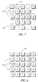
- the radial pattern of pixels used within a 5 by 5 pixel rectangular local neighborhood of pixels is shown in Figure 7.
- the pixel of interest p ij is marked with an X (item 202) while the pixels of the local neighborhood of pixels are marked with an A (items 203).
- the noise form many sources of color digital images is signal dependent.
- the parameter Sfac can be used to vary the degree of noise reduction. Both the Sfac and ⁇ variables are examples of a noise adjustment parameter.
- the calculation of the noise reduced pixel value q ij as the division of the two sums is then calculated. The process is completed for some or all of the pixels contained in the digital image channel and for some or all the digital image channels contained in the color digital image.
- the noise reduced pixel values constitute the noise reduced color digital image.
- the present invention may be used to vary the level of noise reduction achieved by varying the size of the local neighborhood of pixels based on the color weighting factors ⁇ ij .
- Figure 8 shows a 5 by 5 pixel local neighborhood of pixels used to achieve more noise reduction while Figure 9 shows a 3 by 3 pixel local neighborhood of pixels used to achieve less noise reduction.
- the same color weighting factors ⁇ ij as described above are used to determine the size of the local neighborhood of pixels.
- the range of ⁇ ij values is divided into different segments relating to the different sizes of local neighborhood of pixels.
- pixels of interest with corresponding color weighting factors with values in the lowest one third of the range of of ⁇ ij values use a 3 by 3 pixel local neighborhood of pixels
- the middle third of ⁇ ij values use a 5 by 5 pixel local neighborhood of pixels
- the highest one third of the range of of ⁇ ij values use a 7 by 7 pixel local neighborhood of pixels.
- the sigma filter as described by Lee is one example of a pixel difference filter that can be used in the present invention.
- the central aspect of a pixel difference filter is a spatial filter that calculates a noise free pixel estimate based on the pixel values in a local neighborhood of pixels about a pixel of interest, wherein the influence of each local pixel is based on the difference between the local pixel value and a reference numerical value derived from the pixels in the local neighborhood.
- the preferred embodiment of a pixel difference filter used in the present invention uses the pixel of interest as the reference numerical value. Other values such as the average of pixels in the local neighborhood can also be used as the reference numerical value.
- a pixel difference filter is the Inverse Gradient Filter described by D. C. C. Wang et al. in their published paper Gradient Inverse Weighted Smoothing Scheme and the Evaluation of its Performance , Computer Graphics and Image Processing Vol 15, p. 167-181, 1981.
- This algorithm produced a noise cleaned image by taking a non-linear weighting of the local pixel values from a rectangular sampling region about the center pixel. The weighting factor was based on the magnitude difference between the center pixel and the surrounding pixel value.
- Another alternative embodiment of the present invention uses a median filter as the basic noise reduction logic to form the noise reduced pixel value.
- the color weighting factors ⁇ ij are used to vary the size of the local neighborhood of pixels.
- the preferred and alternative embodiment of the present invention both use the color information of pixels in the source color digital image to calculate a weighting factor which is used to vary the level of noise reduction achieved. It has been shown that the level of noise reduction can be varied by regulating the size of the local neighborhood of pixels used or by varying a regulation variable directly. Since the color information based weighting factor (the color weighting factor ⁇ ij ) is based on a near continuous function (a function that can assume three or more values) of the pixel of interest color coordinates, the resultant noise reduction achieved is also continuous or near continuous. Thus color digital images processed with the present invention do not exhibit sharp or discontinuous variations in noise reduction.
Abstract
Description
- The present invention relates to a method, apparatus, and computer program for processing color digital images to reduce noise.
- The image structure of color digital images can be thought of as made up of two components: a signal component and a noise component. In many digital imaging applications it is desirable to amplify the signal component while in the same instance reduce the noise component. The difficulty of achieving both these goals for a color digital image processing application simultaneously lies in the inherent differentiability of the signal and noise components. No technology at present achieves a perfect decomposition of image data into these two components. Thus current image processing noise reduction algorithms result in either some loss of the signal component or not enough noise component removal or both. It has been recognized in the image photographic field that the color of different real world objects can be used to advantage with regard to signal and noise processing.
- In US. Patent # 5,682,443 Gough and MacDonald disclose a method of processing color digital images for the purposes of spatial sharpness characteristic enhancement. In this disclosure, a method of unsharp masking is discussed which separates an original color digital image into two parts based on the spatial frequency content of the original color digital image. The difference between the original pixel values and a low spatial frequency component of the original pixel values forms a fringe component, or high spatial frequency component. Gough and MacDonald teach a method of modifying the fringe component based on the color of either the low spatial frequency component or the original pixel values. Their method also discloses that the preferred method of implementing this feature uses a continuous mathematical function of color. The method disclosed by Gough and MacDonald takes advantage of color as an image characteristic for enhancing the spatial detail. However, the unsharp masking procedure employed by Gough and MacDonald is designed to vary the amplification of the signal component and is not effective for the purposes of reducing of the noise component.
- In US. Patent # 4,689,666 Hatanaka discloses a method of using the color characteristics of a color digital image for the purposes of reducing the noise component of the color digital image. In the method disclosed, Hatanaka describes a process of extracting color data for each picture element of the image, discriminating regions of the color digital image exhibiting a specific color on the basis of the extracted color data, and subjecting the image signal to spatial image processing for elimination of noise under different processing conditions for regions exhibiting the specific color and the remaining regions not exhibiting the specific color. Thus the method taught by Hatanaka has as a fundamental step the segmentation, or discrimination, of each pixel as belonging to the specific color or not belonging to the specific color. The step color discrimination can lead to unevenness in the processed images due to the on/off nature of the color identification process.
- There is thus a need for a noise reduction algorithm which uses the color characteristic of a color digital image to advantage the process of noise reduction in a smooth and even manner without producing switching artifacts typical of segmentation based decision based methods.
- The need is met according to the present invention by providing a digital image processing method for reducing the noise of a color digital image having pixel values, that includes the steps of: identifying one or more color regions in color space; identifying a pixel of interest in the color digital image; calculating a color weighting factor for the pixel of interest, the color weighting factor being a near continuous function of the one or more color regions; using the color weighting factor and the values of pixels sampled from a local neighborhood of pixels about the pixel of interest to calculate a noise reduced pixel value; replacing the original value of the pixel of interest with the noise reduced pixel value; and repeating the steps for other pixels in the color digital image.
- The present invention has the advantage that noise reduction is applied to preferentially treat different regions of color space in a continuous fashion so that spatial artifacts are avoided. It has the further advantage that different color regions, such as skin, sky, and grass can be treated differently to obtain a pleasing image.
- Figure 1 is a pictorial diagram showing a color digital image and a visualization of the corresponding color-based noise reduction processing produced with the application of the present invention;
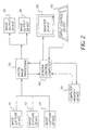
- Figure 2 is a block diagram showing an image processing system suitable for practicing the present invention;
- Figure 3 is a block diagram showing image processing according to one embodiment of the present invention;
- Figure 4 is a block diagram showing image processing according to a preferred embodiment the present invention;
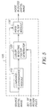
- Figure 5 is a block diagram showing the noise reduction module according to the preferred embodiment of the present invention;
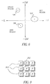
- Figure 6 is a diagram showing different color regions as practiced by the present invention;
- Figure 7 is a block diagram showing a radial pattern local neighborhood of pixels used by to the present invention;
- Figure 8 is a block diagram showing a 5 by 5 pixel rectangular local neighborhood of pixels module used by to the present invention; and
- Figure 9 is a block diagram showing a 3 by 3 pixel rectangular local neighborhood of pixels module used by to the present invention.
-
- A color digital image is comprised of a two or more digital image channels. Each digital image channel is comprised of a two-dimensional array of pixels. Each pixel value relates to the amount of light received by the imaging capture device corresponding to the geometrical domain of the pixel. For color imaging applications a color digital image will typically consist of red, green, and blue digital image channels. Other configurations are also practiced, e.g. cyan, magenta, and yellow digital image channels. For monochrome applications, the digital image consists of one digital image channel. Motion imaging applications can be thought of as a time sequence of color digital images. Those skilled in the art will recognize that the present invention can be applied to, but is not limited to, a color digital image for any of the above mentioned applications.
- Although the present invention describes a digital image channel as a two dimensional array of pixel values arranged by rows and columns, those skilled in the art will recognize that the present invention can be applied to mosaic (non rectilinear) arrays with equal effect. Those skilled in the art will also recognize that although the present invention describes replacing original pixel values with tone brightness adjusted pixel values, it is also trivial to form a new color digital image with the noise cleaned pixel values and retain the original pixel values.
- Figure 1 shows a pictorial diagram of one of the important aspects of the present invention. An example source color digital image is shown as input to a first processing module which produces a color difference value for each pixel. A second processing module produces a color weighting mask This color weighting mask is used by a third processing module to produce a noise reduced color digital image.
- The present invention may be implemented in computer hardware. Referring to Figure 2, the following description relates to a digital imaging system which includes an image capture device 10, a digital image processor 20, an image output device 30, and a general control computer 40. The system may include a monitor device 50 such as a computer console or paper printer. The system may also include an input device control for an operator such as a keyboard and or mouse pointer. Still further, as used herein, the present invention may be implemented as a computer program and may be stored in a computer memory device 70 i.e. a computer readable storage medium, which may comprise, for example: magnetic storage media such as a magnetic disk (such as a floppy disk) or magnetic tape; optical storage media such as an optical disc, optical tape, or machine readable bar code; solid state electronic storage devices such as random access memory (RAM), or read only memory (ROM); or any other physical device or medium employed to store a computer program. Before describing the present invention, it facilitates understanding to note that the present invention is preferably utilized on any well-known computer system, such as a personal computer.
- Multiple capture devices 10 are shown illustrating that the present invention may be used for color digital images derived from a variety of imaging devices. For example, Figure 2 may represent a digital photofinishing system where the image capture device 10 is a conventional photographic film camera for capturing a scene on color negative or slide film and a film scanner device for scanning the developed image on the film and producing a color digital image. The digital image processor 20 provides the means for processing the color digital images to produce pleasing looking images on the intended output device or media. Multiple image output devices 30 are shown illustrating that the present invention may be used in conjunction with a variety of output devices which may include a digital photographic printer and soft copy display. The digital image processor 20 processes the color digital image to adjust the overall brightness and/or tone scale of the color digital image in a manner such that a pleasing looking image is produced by a image output device 30. The interaction between these processing steps is explained in more detail below.
- The digital image processor 20 shown in Figure 2 is illustrated in more detail in Figure 3. The general form of the digital image processor 20 employed by the present invention is a cascaded chain of image processing modules. The source color digital image is received by the digital image processor 20 which produces on output a processed color digital image. Each image processing module contained within the digital image processor 20 receives a color digital image, modifies the color digital image or derives some information from the color digital image, and produces passes its output color digital image to the next image processing module. Two enhancement transform modules 22 are shown as the first and last image processing modules within the digital image processor 20 to illustrate that the present invention can be used in conjunction with other image processing modules. Examples of enhancement transform modules 22 might include, but are not limited to, modules designed to sharpen spatial detail, enhance color, enhance contrast, and enhance the tone scale of a color digital image. It should be understood within the context of the discussion of the present invention that the term input color digital image and output color digital image refers to the color digital image received and produced by an image processing module respectively.
- The cascaded chain of image processing modules employed by the present invention is shown in Figure 4. The source color digital image produced by the capture device 10 is received by a color transform module 24. The output color digital image produced by the color transform module 24 is received by the logarithm transform module 26. The output color digital image produced by the logarithm transform module 26 is received by the noise reduction module 100. The output color digital image produced by the noise reduction module 100 constitutes the noise reduced color digital image produced by the digital image processor 20 shown in Figure 2.
- A characteristic of the color digital image produced by a capture device 10 which can impact the effectiveness of the present invention is the color space metric associated with the capture devices which produce color digital images. Typically the capture device 10 incorporates three color spectral filters which determine the relative amounts of colored light received by the photosensitive transducer elements. Depending on the characteristics of the spectral filters, better results may be achieved with the present invention if a color transform is applied to the color digital image preceding the application of the noise reduction module 100. Although the application of a color transform is not required to practice the present invention, optimal results may be achieved if a color transform is applied based on the spectral characteristics of the input and/or output devices.
- The color transform method employed by the present invention is a 3 by 4 matrix transformation. This transformation generates new color pixel values as linear combinations of the input color pixel values. The input color digital image consists of a red, green, and blue digital image channels. Each digital image channel contains the same number of pixels. Let Rij, Gij, and Bij refer to the pixel values corresponding to the red, green, and blue digital image channels located at the ith row and jth column. Let R'ij, G'ij, and B'ij refer to the transformed pixel values of the output color digital image. The 3 by 4 matrix transformation relating the input and output pixel values is as follows:
- A characteristic of the color digital image produced by a capture device 10 which can impact the effectiveness of the present invention is the code value domain associated with capture device which produce color digital images. Typically the capture device 10 incorporates a photosensitive transducer element which converts the imaged light into an analog electrical signal. An analog-to-digital converter device is then used to transform the analog electrical signal into a set of digital code values. These digital code values constitute the numerical pixel values of the output color digital image produced by the capture device 10. The code value domain characteristic of a capture device 10 describes the mathematical relationship between the output digital code values and the input intensity of received light.
- Many photosensitive transducer elements have a linear characteristic response, i.e. the electrical analog signal produced is linearly proportional to the intensity of received light. Many analog-to-digital converter devices have a linear characteristic response, i.e. the digital code values produced are linearly proportional to the intensity of received electrical analog signal. If a linear transducer element and a linear analog-to-digital converter are employed by a capture device the resulting output code values will have a linear relationship with the intensity of the received light. Thus the color digital images produced by capture devices which exhibit this linear relationship have numerical pixel values which have a linear relationship with the original intensity of light. Such color digital images will be termed to have a linear code value domain property.
- The present invention may be applied to color digital images which have a linear code value domain property. However, better results are obtained with the present invention if the input color digital image has a logarithmic code value domain property, i.e. the numerical pixel values have a logarithmic relationship with the original intensity of light. The logarithm transform module 26 shown in Figure 4 is employed to change the code value domain property of the color digital image input to the brightness tone scale module 100. The logarithm transform module 26 generates a look-up-table (LUT) transform populated with numerical values which have a logarithmic relationship to the LUT indices. Let pij refer to the pixel values corresponding to a digital image channel located at the ith row and jth column. Let p'ij refer to the transformed pixel values of the output color digital image produced with the LUT transform. The LUT transform relating the input and output pixel values is as follows:
- The mathematical operation performed by the logarithm transform module 26 is an example of single valued function transform, i.e. each input value has a single corresponding output value. This operation may be implemented as a succession of mathematical operations (add, log, multiple, add) in computer hardware or software. However, for large color digital images the same operation is more computationally efficient implemented as a LUT transformation. For the purposes of the present invention, the LUT implementation and the succession of mathematical operations implementation will be referred to as logarithmic transforms.
- The noise reduction module 100 depicted in Figure 4 is shown in more detail in Figure 5. The noise reduction module 100 performs the tasks of calculating a color weighting mask and using the color weighting mask in conjunction with a noise reduction filter to modify a source color digital image to produce a noise reduced color digital image with a less discernable noise than source color digital image. Let the source color digital image refer to color digital image produced by the previous image processing module in the digital image processor 20.
- Referring to Figure 5, the source color digital image channels of the source color digital image, typically three channels corresponding to red, green, and blue pixel information, are received by the luminance-chrominance module 110. This module produces three digital image channels; a luminance digital image channel and two chrominance digital image channels. The chrominance digital image channels are received by the color weighting factor generator 120 which produces a color weighting mask . The noise filter module 130 receives the color weighting mask and the source color digital image and produces a noise reduced color digital image.
- The analysis phase of the noise reduction module 100 depicted in Figure 5 employs a luminance-chrominance module 110 to produce a luminance/chrominance, or LCC color digital image, version of the input color digital image consisting of a luminance digital image channel and two chrominance digital image channels denoted by GM and IL. The luminance-chrominance module 110 employs a 3x3 matrix transformation to convert the red, green, and blue pixel values into luminance and chrominance pixel values. Let Rij, Gij, and Bij refer to the pixel values corresponding to the red, green, and blue digital image channels located at the ith row and jth column. Let Lij, GMij, and ILij refer to the transformed luminance, first chrominance, and second chrominance pixel values respectively of the output LCC color digital image. The 3x3 matrix transformation relating the input and output pixel values is as follows:
- A color weighting mask is a two dimensional array of numerical weighting factors. The numerical weighting factors of a color weighting mask relate to the relative importance of pixel location. Color weighting mask s are used by the present invention in conjunction with a digital image channel to adjust or regulate the spatial processing of the pixels values of a color digital image.
- Referring to Figure 5, the color weighting factor generator 120 receives the chrominance digital image channels from the luminance-chrominance module 110 and a set of predetermined color region poles. Each color region pole includes a GM and IL value. These two values form a 2-dimensional coordinate location in color space. Let GMk and ILk denote the values of the kth color region pole and let N denote the number of color region poles in the set. Each color region pole represents a unique color in 2-dimensional color space for which the noise reduction processing of the source color digital image will be preferentially treated.
- Referring to Figure 6, three regions differentiated for noise reduction processing are identified as a blue sky region 122, a green grass region 124 and a skin region 126. At the center of each of these color regions is the location of the of a corresponding color region pole. The actual numerical value of the GM and IL components of the color region poles depends on the color and/or logarithmic transformation used, For a given digital imaging application, once the color and/or logarithmic transformation experimentation with typical imagery is used to determine the numerical value of the color region pole GM and IL values.
- Each color region pole can designate either emphasized or de-emphasized noise reduction processing of the pixels values of a color digital image depending the preference of the digital image processing application design goals. For the preferred embodiment of the present invention, design goal of reducing noise in color digital images includes a color region pole for the blue sky region of color space emphasizes more noise reduction while the color region pole for the green grass region of color space de-emphasizes noise reduction (less effective noise reduction). Consequently, color digital images processed with this configuration of the present invention will result in more noise removed from image blue sky regions than for image green grass regions.
- The emphasis or de-emphasis of noise reduction processing is accomplished by calculating a color weighting factor for each pixel processed. The color weighting factor is a single numerical value which encompasses the sum total of emphasis and de-emphasis effects from all the color region poles in the set of color region poles. For each color region pole a two chrominance distance values, represented by x and y, are calculated as the distance from the location in color space of the ijth pixel to the kth color region pole for each color space dimension. Let yijk represent the distance between the kth color region pole GM value and the GM value of the ijth pixel as
- Additionally, the Gaussian quantion can be rotated in color space to provide more flexibility in defining a color region. Let k represent the rotation angle in color space for the kth color region pole and let x'ijk and y'ijk represent the rotated coordinates and given by the equation
- The values of the color pole emphasis factor ακ can be adjusted for more or less effect depending on the digital imaging application. The preferred embodiment of the present invention uses a value of 1.0 for αo and 0.25 for ακ sky and flesh color regions and -0.25 for the green grass color region. The values for σxk and σyk are set to values identified uniquely for the flesh color, green grass color, and blue sky color regions. The present invention can be practiced with many different choices of chrominance value descriptions. However, to achieve optimum results, the values of the σxk for and σyk variables should be adjusted if a equation than as given by (5) is used to generate the chrominance values.
- The color weighting factor for the ijth pixel ωij is given by the sum of all the individual color pole weighting factors k as
- An alternative embodiment of the present invention calculates the color weighting factors ωij by multiplicatively combining the individual color pole weighting factors k as
- An alternative embodiment of the present invention bases the coordinate pair GM and IL values on a spatially filtered version of the pixels of the source color digital image. A spatial smoothing filter designed to reduce the amplitude of high spatial frequency modulations is used to filter the source color digital image. A 2-dimensional Gaussian filter is used as the spatial smoothing filter. The filtered version color digital image is processed with the luminance chrominance module 110 to produce the color space coordinates as used by the preferred embodiment of the present invention. This alternative embodiment of the present invention requires more computational resources due the additional processing step of spatially filtering. However, for vary noisy color digital images the benefit of this embodiment is a more gradual regulation of the noise reduction achieved.
- Another alternative embodiment of the present invention calculates the color weighting factors ωij for each pixel in the source color digital image and assembles the values into a color weighting mask . This color weighting mask is then filtered with a spatial smoothing filter designed to reduce the amplitude of high spatial frequency modulations. The resulting spatially filtered color weighting mask is then used in similar fashion as described above.
- Those skilled in the art will recognize that the present invention is not limited to three color regions but may be practiced with any number of color regions. Depending on the digital imaging application, any color region which can be found through experimentation as requiring a different level of noise reduction can be targeted as a chrominnace pole coordinate pair.
- The chrominance pixel values of the two chrominance digital image channels are examples of color difference values derived from the pixels of the source color digital image. Although the present invention uses a 2-dimensional color space representation for simplicity and computational efficiency, those skilled in the art will recognize that the present invention can be practiced with color weighting factors calculated from other forms of color difference values calculated in other color space representations, but not limited to, CIELAB (a*,b* or C*,H*), CIELUV, and generalized RGB.
- Referring to Figure 5, the noise filter module 130 receives the source color digital image and the color weighting mask from the color weighting factor generator 120 and uses the color weighting mask to adjust the noise reduction processing.
- The Sigma filter, described by Jong-Sen Lee in the journal article Digital Image Smoothing and the Sigma Filter, Computer Vision, Graphics, and Image Processing Vol 24, p. 255-269, 1983, is a noise reduction algorithm designed to enhance the visual appearance of color digital images. The values of the pixels contained in a local neighborhood of pixels, n by n pixels where n denotes the length of pixels in either the row or column direction, are compared with the value of the center pixel, or pixel of interest. Each pixel in the s local neighborhood of pixels is given a weighting factor of one or zero based on the absolute difference between the value of the pixel of interest and the local neighborhood pixel value. If the absolute value of the pixel value difference is less or equal to a threshold s, the weighting factor if set to one. Otherwise, the weighting factor is set to zero. The numerical constant ε is set to two times the expected noise standard deviation. Mathematically the expression for the calculation of the noise reduced pixel value is given as
- The noise form many sources of color digital images is signal dependent. The signal dependent noise and the chrominance dependent features of the present invention are incorporated into the expression for ε given by
- The present invention may be used to vary the level of noise reduction achieved by varying the size of the local neighborhood of pixels based on the color weighting factors ωij. Figure 8 shows a 5 by 5 pixel local neighborhood of pixels used to achieve more noise reduction while Figure 9 shows a 3 by 3 pixel local neighborhood of pixels used to achieve less noise reduction. The same color weighting factors ωij as described above are used to determine the size of the local neighborhood of pixels. The range of ωij values is divided into different segments relating to the different sizes of local neighborhood of pixels. For example, pixels of interest with corresponding color weighting factors with values in the lowest one third of the range of of ωij values use a 3 by 3 pixel local neighborhood of pixels, the middle third of ωij values use a 5 by 5 pixel local neighborhood of pixels and the highest one third of the range of of ωij values use a 7 by 7 pixel local neighborhood of pixels.
- The sigma filter as described by Lee is one example of a pixel difference filter that can be used in the present invention. The central aspect of a pixel difference filter is a spatial filter that calculates a noise free pixel estimate based on the pixel values in a local neighborhood of pixels about a pixel of interest, wherein the influence of each local pixel is based on the difference between the local pixel value and a reference numerical value derived from the pixels in the local neighborhood. The preferred embodiment of a pixel difference filter used in the present invention uses the pixel of interest as the reference numerical value. Other values such as the average of pixels in the local neighborhood can also be used as the reference numerical value.
- Another example of a pixel difference filter is the Inverse Gradient Filter described by D. C. C. Wang et al. in their published paper Gradient Inverse Weighted Smoothing Scheme and the Evaluation of its Performance, Computer Graphics and Image Processing Vol 15, p. 167-181, 1981. This algorithm produced a noise cleaned image by taking a non-linear weighting of the local pixel values from a rectangular sampling region about the center pixel. The weighting factor was based on the magnitude difference between the center pixel and the surrounding pixel value.
- Another alternative embodiment of the present invention uses a median filter as the basic noise reduction logic to form the noise reduced pixel value. As above, the color weighting factors ωij are used to vary the size of the local neighborhood of pixels.
- The preferred and alternative embodiment of the present invention both use the color information of pixels in the source color digital image to calculate a weighting factor which is used to vary the level of noise reduction achieved. It has been shown that the level of noise reduction can be varied by regulating the size of the local neighborhood of pixels used or by varying a regulation variable directly. Since the color information based weighting factor (the color weighting factor ωij) is based on a near continuous function (a function that can assume three or more values) of the pixel of interest color coordinates, the resultant noise reduction achieved is also continuous or near continuous. Thus color digital images processed with the present invention do not exhibit sharp or discontinuous variations in noise reduction.
Claims (10)
- A digital image processing method for enhancing a color digital image having pixel values, comprising the steps of:a) identifying a pixel of interest in the color digital image;b) identifying a local neighborhood of pixels about the pixel of interest;c) using the values of pixel sampled from the local neighborhood to calculate a color weighting factor for the pixel of interest, the color weighting factor being a near continuous function;d) using the color weighting factor and the values of pixels sampled from the local neighborhood to calculate a noise reduced pixel value;e) replacing the value of the pixel of interest with the noise reduced pixel value; andf) repeating steps (a) through (e) for other pixels in the color digital image.
- The method claimed in claim 1, wherein step c) further comprises the steps of(i) identifying one or more color regions in color space;(ii) calculating a pixel color coordinate in color space for the pixel of interest;(iii) calculating a color weighting factor as a near continuous function of the pixel color coordinate and the color regions.
- The method claimed in claim 1, wherein step d) further comprises the step of calculating differences of pixel values sampled from the local neighborhood and using the differences of pixels values and the color weighting factor to calculate a noise reduced pixel value.
- The method claimed in claim 3, wherein step d) further comprises the step of comparing the differences of pixel values with a threshold parameter and using the color weighting factor to vary the value of the threshold parameter.
- The method claimed in claim 4, wherein step d) further comprises the step of varying the threshold parameter as a function of an expected noise level.
- The method claimed in claim 5, wherein the expected noise level is also a function of the pixel values of the local neighborhood.
- The method claimed in claim 1, wherein step (d) further comprises the step of using the color weighting factor to vary the size of the local neighborhood.
- The method claimed in claim 2, wherein step (d) further comprises the step of using the color weighting factor to vary the size of the local neighborhood.
- The method claimed in claim 7, wherein the noise reduced pixel value is derived from a statistical quantity of the pixel values sampled from a local neighborhood.
- The method claimed in claim 9, wherein the statistical quantity is a mean, median, minimum, or maximum.
Applications Claiming Priority (2)
| Application Number | Priority Date | Filing Date | Title |
|---|---|---|---|
| US620000 | 2000-07-20 | ||
| US09/620,000 US6807300B1 (en) | 2000-07-20 | 2000-07-20 | Noise reduction method utilizing color information, apparatus, and program for digital image processing |
Publications (3)
| Publication Number | Publication Date |
|---|---|
| EP1174824A2 true EP1174824A2 (en) | 2002-01-23 |
| EP1174824A3 EP1174824A3 (en) | 2003-01-29 |
| EP1174824B1 EP1174824B1 (en) | 2008-01-09 |
Family
ID=24484172
Family Applications (1)
| Application Number | Title | Priority Date | Filing Date |
|---|---|---|---|
| EP01202528A Expired - Lifetime EP1174824B1 (en) | 2000-07-20 | 2001-07-02 | Noise reduction method utilizing color information, apparatus, and program for digital image processing |
Country Status (4)
| Country | Link |
|---|---|
| US (1) | US6807300B1 (en) |
| EP (1) | EP1174824B1 (en) |
| JP (1) | JP4804660B2 (en) |
| DE (1) | DE60132278T2 (en) |
Cited By (13)
| Publication number | Priority date | Publication date | Assignee | Title |
|---|---|---|---|---|
| GB2400257A (en) * | 2003-04-05 | 2004-10-06 | Autodesk Canada Inc | Removal of grain |
| US6807300B1 (en) * | 2000-07-20 | 2004-10-19 | Eastman Kodak Company | Noise reduction method utilizing color information, apparatus, and program for digital image processing |
| EP1377030A3 (en) * | 2002-06-05 | 2005-02-09 | Canon Kabushiki Kaisha | Image processing apparatus, image processing method, and computer program for removing low-frequency noise in image data |
| US6891977B2 (en) | 2002-02-27 | 2005-05-10 | Eastman Kodak Company | Method for sharpening a digital image without amplifying noise |
| WO2006126949A1 (en) * | 2005-05-27 | 2006-11-30 | Telefonaktiebolaget Lm Ericsson (Publ) | Weight based image processing |
| EP1755329A1 (en) * | 2005-08-16 | 2007-02-21 | Océ-Technologies B.V. | Conversion method, apparatus and computer program for converting a digital image obtained by a scanner |
| US7508542B2 (en) | 2003-06-11 | 2009-03-24 | Murata Kikai Kabushiki Kaisha | Image forming device and image forming method |
| RU2407222C2 (en) * | 2005-05-27 | 2010-12-20 | Телефонактиеболагет Лм Эрикссон (Пабл) | Processing of images based on weights |
| CN102263885A (en) * | 2010-05-27 | 2011-11-30 | 于培宁 | Method for denoising image sequence |
| US8204334B2 (en) | 2006-06-29 | 2012-06-19 | Thomson Licensing | Adaptive pixel-based filtering |
| TWI392334B (en) * | 2009-04-22 | 2013-04-01 | Mstar Semiconductor Inc | Image processing apparatus and image processing method |
| US8467626B2 (en) | 2006-09-29 | 2013-06-18 | Thomson Licensing | Automatic parameter estimation for adaptive pixel-based filtering |
| CN110166716A (en) * | 2018-02-14 | 2019-08-23 | 佳能株式会社 | Image processing equipment and image processing method |
Families Citing this family (30)
| Publication number | Priority date | Publication date | Assignee | Title |
|---|---|---|---|---|
| US7319415B2 (en) * | 2002-05-01 | 2008-01-15 | Thomson Licensing | Chroma deblocking filter |
| US7065255B2 (en) * | 2002-05-06 | 2006-06-20 | Eastman Kodak Company | Method and apparatus for enhancing digital images utilizing non-image data |
| JP3862620B2 (en) * | 2002-06-28 | 2006-12-27 | キヤノン株式会社 | Image processing apparatus and image processing method |
| CN1300744C (en) * | 2003-12-09 | 2007-02-14 | 香港中文大学 | Automatic method for modifying digital image and system of adopting the method |
| US7257271B2 (en) * | 2003-12-17 | 2007-08-14 | Eastman Kodak Company | Noise reduction in color digital images using pyramid decomposition |
| DE602005016067D1 (en) * | 2005-01-11 | 2009-10-01 | St Microelectronics Res & Dev | Improved digital filtering |
| US7606437B2 (en) * | 2005-01-11 | 2009-10-20 | Eastman Kodak Company | Image processing based on ambient air attributes |
| GB0505443D0 (en) * | 2005-03-17 | 2005-04-20 | Dmist Technologies Ltd | Image processing methods |
| CA2602906A1 (en) * | 2005-03-22 | 2006-09-28 | Olympus Corporation | Image processor and endoscope apparatus |
| US7885478B2 (en) * | 2005-05-19 | 2011-02-08 | Mstar Semiconductor, Inc. | Noise reduction method and noise reduction apparatus |
| TWI336595B (en) * | 2005-05-19 | 2011-01-21 | Mstar Semiconductor Inc | Noise reduction method |
| JP4776308B2 (en) * | 2005-09-05 | 2011-09-21 | 株式会社東京精密 | Image defect inspection apparatus, image defect inspection system, defect classification apparatus, and image defect inspection method |
| US7551232B2 (en) * | 2005-11-14 | 2009-06-23 | Lsi Corporation | Noise adaptive 3D composite noise reduction |
| US7620243B2 (en) * | 2005-12-14 | 2009-11-17 | Seiko Epson Corporation | Noise reduction for primary tones for image replication systems |
| JP2007201541A (en) * | 2006-01-23 | 2007-08-09 | Ricoh Co Ltd | Image processing apparatus, imaging apparatus, image processing method, and image processing program |
| US9143657B2 (en) | 2006-01-24 | 2015-09-22 | Sharp Laboratories Of America, Inc. | Color enhancement technique using skin color detection |
| JP4977395B2 (en) * | 2006-04-14 | 2012-07-18 | 富士フイルム株式会社 | Image processing apparatus and method |
| US7903900B2 (en) * | 2007-03-30 | 2011-03-08 | Hong Kong Applied Science And Technology Research Institute Co., Ltd. | Low complexity color de-noising filter |
| US8824831B2 (en) | 2007-05-25 | 2014-09-02 | Qualcomm Technologies, Inc. | Advanced noise reduction in digital cameras |
| US7995856B2 (en) | 2007-05-25 | 2011-08-09 | Zoran Corporation | Dynamic range compensation-dependent noise reduction |
| US7889942B2 (en) * | 2007-05-25 | 2011-02-15 | Zoran Corporation | Dynamic range compensation-dependent noise reduction |
| US7983503B2 (en) | 2007-05-25 | 2011-07-19 | Zoran Corporation | Advanced noise reduction in digital cameras |
| US8106972B2 (en) * | 2008-01-18 | 2012-01-31 | Zoran Corporation | Apparatus and method for noise reduction with 3D LUT |
| US8031202B2 (en) * | 2008-03-11 | 2011-10-04 | Xerox Corporation | Color transfer between images through color palette adaptation |
| JP2010142464A (en) * | 2008-12-19 | 2010-07-01 | Panasonic Corp | Image processor and image input device |
| TWI387313B (en) * | 2009-05-21 | 2013-02-21 | Novatek Microelectronics Corp | Circuit and method for image processing |
| US8782558B1 (en) | 2012-11-28 | 2014-07-15 | Advanced Testing Technologies, Inc. | Method, program and arrangement for highlighting failing elements of a visual image |
| US9495584B1 (en) * | 2015-06-05 | 2016-11-15 | Digital Signal Corporation | System and method for facial recognition using images captured from a target illuminated with infrared light |
| JP6975070B2 (en) * | 2018-02-27 | 2021-12-01 | シャープ株式会社 | Image processing device, image processing method, and image processing program |
| US20230051281A1 (en) * | 2020-04-21 | 2023-02-16 | Hewlett-Packard Development Company, L.P. | Color correction of an image |
Citations (3)
| Publication number | Priority date | Publication date | Assignee | Title |
|---|---|---|---|---|
| JPH09114975A (en) * | 1995-10-23 | 1997-05-02 | Dainippon Screen Mfg Co Ltd | Device and method for removing noise in color image |
| US5689590A (en) * | 1992-04-30 | 1997-11-18 | Ricoh Company, Ltd. | Background noise removing apparatus and method applicable to color image processing apparatus |
| US5999279A (en) * | 1996-02-28 | 1999-12-07 | Minolta Co., Ltd. | Image forming apparatus having an MTF correction unit |
Family Cites Families (8)
| Publication number | Priority date | Publication date | Assignee | Title |
|---|---|---|---|---|
| JPS61161091A (en) | 1985-01-08 | 1986-07-21 | Fuji Photo Film Co Ltd | Image processing method |
| DE69428148T2 (en) | 1993-03-24 | 2002-05-29 | Fujifilm Electronic Imaging | Color change of pictures |
| US5903681A (en) * | 1996-07-24 | 1999-05-11 | Eastman Kodak Company | Reducing edge artifacts on a digital printer |
| US5768440A (en) * | 1996-12-18 | 1998-06-16 | Xerox Corporation | Adaptive noise removal for video images with less correction of current pixel for higher variations between surrounding pixels |
| JP3654327B2 (en) * | 1997-05-26 | 2005-06-02 | 富士ゼロックス株式会社 | Color conversion device |
| US6625325B2 (en) * | 1998-12-16 | 2003-09-23 | Eastman Kodak Company | Noise cleaning and interpolating sparsely populated color digital image using a variable noise cleaning kernel |
| US6807300B1 (en) * | 2000-07-20 | 2004-10-19 | Eastman Kodak Company | Noise reduction method utilizing color information, apparatus, and program for digital image processing |
| US6856704B1 (en) * | 2000-09-13 | 2005-02-15 | Eastman Kodak Company | Method for enhancing a digital image based upon pixel color |
-
2000
- 2000-07-20 US US09/620,000 patent/US6807300B1/en not_active Expired - Lifetime
-
2001
- 2001-07-02 EP EP01202528A patent/EP1174824B1/en not_active Expired - Lifetime
- 2001-07-02 DE DE60132278T patent/DE60132278T2/en not_active Expired - Lifetime
- 2001-07-11 JP JP2001211282A patent/JP4804660B2/en not_active Expired - Fee Related
Patent Citations (3)
| Publication number | Priority date | Publication date | Assignee | Title |
|---|---|---|---|---|
| US5689590A (en) * | 1992-04-30 | 1997-11-18 | Ricoh Company, Ltd. | Background noise removing apparatus and method applicable to color image processing apparatus |
| JPH09114975A (en) * | 1995-10-23 | 1997-05-02 | Dainippon Screen Mfg Co Ltd | Device and method for removing noise in color image |
| US5999279A (en) * | 1996-02-28 | 1999-12-07 | Minolta Co., Ltd. | Image forming apparatus having an MTF correction unit |
Non-Patent Citations (2)
| Title |
|---|
| LEE J-S: "DIGITAL IMAGE SMOOTHING AND THE SIGMA FILTER" COMPUTER VISION GRAPHICS AND IMAGE PROCESSING, ACADEMIC PRESS, DULUTH, MA, US, vol. 24, 1983, pages 255-269, XP000199489 * |
| PATENT ABSTRACTS OF JAPAN vol. 1997, no. 09, 30 September 1997 (1997-09-30) & JP 09 114975 A (DAINIPPON SCREEN MFG CO LTD), 2 May 1997 (1997-05-02) * |
Cited By (23)
| Publication number | Priority date | Publication date | Assignee | Title |
|---|---|---|---|---|
| US6807300B1 (en) * | 2000-07-20 | 2004-10-19 | Eastman Kodak Company | Noise reduction method utilizing color information, apparatus, and program for digital image processing |
| US6891977B2 (en) | 2002-02-27 | 2005-05-10 | Eastman Kodak Company | Method for sharpening a digital image without amplifying noise |
| US8306357B2 (en) | 2002-06-05 | 2012-11-06 | Canon Kabushiki Kaisha | Image processing apparatus, image processing method, and computer program |
| EP1377030A3 (en) * | 2002-06-05 | 2005-02-09 | Canon Kabushiki Kaisha | Image processing apparatus, image processing method, and computer program for removing low-frequency noise in image data |
| US8744209B2 (en) | 2002-06-05 | 2014-06-03 | Canon Kabushiki Kaisha | Image processing apparatus and image processing method for visually reducing noise components contained in a low frequency range of image data |
| US8023764B2 (en) | 2002-06-05 | 2011-09-20 | Canon Kabushiki Kaisha | Image processing apparatus, image processing method, and a program, for removing low-frequency noise from image data |
| US7315646B2 (en) | 2003-04-05 | 2008-01-01 | Autodesk Canada Co. | Degraining image data |
| GB2400257A (en) * | 2003-04-05 | 2004-10-06 | Autodesk Canada Inc | Removal of grain |
| US7508542B2 (en) | 2003-06-11 | 2009-03-24 | Murata Kikai Kabushiki Kaisha | Image forming device and image forming method |
| US9466125B2 (en) | 2005-05-27 | 2016-10-11 | Telefonaktiebolaget Lm Ericsson (Publ) | Weight based image processing |
| RU2407222C2 (en) * | 2005-05-27 | 2010-12-20 | Телефонактиеболагет Лм Эрикссон (Пабл) | Processing of images based on weights |
| US9087365B2 (en) | 2005-05-27 | 2015-07-21 | Telefonaktiebolaget L M Ericsson (Publ) | Weight based image processing |
| WO2006126949A1 (en) * | 2005-05-27 | 2006-11-30 | Telefonaktiebolaget Lm Ericsson (Publ) | Weight based image processing |
| EP1755329A1 (en) * | 2005-08-16 | 2007-02-21 | Océ-Technologies B.V. | Conversion method, apparatus and computer program for converting a digital image obtained by a scanner |
| US7646911B2 (en) | 2005-08-16 | 2010-01-12 | Oce-Technologies B.V. | Conversion method, apparatus and computer program for converting a digital image obtained by a scanner |
| US8204334B2 (en) | 2006-06-29 | 2012-06-19 | Thomson Licensing | Adaptive pixel-based filtering |
| US8467626B2 (en) | 2006-09-29 | 2013-06-18 | Thomson Licensing | Automatic parameter estimation for adaptive pixel-based filtering |
| TWI392334B (en) * | 2009-04-22 | 2013-04-01 | Mstar Semiconductor Inc | Image processing apparatus and image processing method |
| CN102263885A (en) * | 2010-05-27 | 2011-11-30 | 于培宁 | Method for denoising image sequence |
| CN102263885B (en) * | 2010-05-27 | 2016-08-03 | 于培宁 | A kind of noise-reduction method of image sequence |
| CN110166716A (en) * | 2018-02-14 | 2019-08-23 | 佳能株式会社 | Image processing equipment and image processing method |
| US11100610B2 (en) | 2018-02-14 | 2021-08-24 | Canon Kabushiki Kaisha | Image processing apparatus, image processing method, and storage medium |
| CN110166716B (en) * | 2018-02-14 | 2022-03-25 | 佳能株式会社 | Image processing apparatus and image processing method |
Also Published As
| Publication number | Publication date |
|---|---|
| JP2002083293A (en) | 2002-03-22 |
| JP4804660B2 (en) | 2011-11-02 |
| DE60132278T2 (en) | 2009-01-02 |
| EP1174824A3 (en) | 2003-01-29 |
| US6807300B1 (en) | 2004-10-19 |
| DE60132278D1 (en) | 2008-02-21 |
| EP1174824B1 (en) | 2008-01-09 |
Similar Documents
| Publication | Publication Date | Title |
|---|---|---|
| US6807300B1 (en) | Noise reduction method utilizing color information, apparatus, and program for digital image processing | |
| US7181086B2 (en) | Multiresolution method of spatially filtering a digital image | |
| JP4210577B2 (en) | Method for enhancing gradation and spatial characteristics of digital images using selective spatial filters | |
| EP1209621B1 (en) | A method for enhancing a digital image based upon pixel color | |
| US6681054B1 (en) | Noise reduction method utilizing probabilistic weighting, apparatus, and program for digital image processing | |
| KR101161471B1 (en) | Optical imaging systems and methods utilizing nonlinear and/or spatially varying image processing | |
| JP4460839B2 (en) | Digital image sharpening device | |
| US8514303B2 (en) | Advanced imaging systems and methods utilizing nonlinear and/or spatially varying image processing | |
| JP4456819B2 (en) | Digital image sharpening device | |
| EP1227437A2 (en) | A multiresolution based method for removing noise from digital images | |
| JP4498671B2 (en) | Method and system for improving image characteristics based on image content | |
| US6801672B1 (en) | Removing noise from a color image using wavelets | |
| US8717456B2 (en) | Optical imaging systems and methods utilizing nonlinear and/or spatially varying image processing | |
| EP1111907A2 (en) | A method for enhancing a digital image with noise-dependant control of texture | |
| US7672528B2 (en) | Method of processing an image to form an image pyramid | |
| KR20040044556A (en) | Image processing method, apparatus, and program | |
| JP2001229377A (en) | Method for adjusting contrast of digital image by adaptive recursive filter | |
| US6614944B1 (en) | Image enhancement filter with adaptive threshold | |
| EP1111906A2 (en) | A method for enhancing the edge contrast of a digital image independently from the texture | |
| JP2003150956A (en) | Method for spatial filtering digital image for noise elimination, noise estimation or digital image highlighting | |
| WO2004036499A1 (en) | A method for interpolation and sharpening of images | |
| US7430334B2 (en) | Digital imaging systems, articles of manufacture, and digital image processing methods | |
| US7269295B2 (en) | Digital image processing methods, digital image devices, and articles of manufacture | |
| US7133569B1 (en) | Aliasing artifact attenuation system |
Legal Events
| Date | Code | Title | Description |
|---|---|---|---|
| PUAI | Public reference made under article 153(3) epc to a published international application that has entered the european phase |
Free format text: ORIGINAL CODE: 0009012 |
|
| AK | Designated contracting states |
Kind code of ref document: A2 Designated state(s): AT BE CH CY DE DK ES FI FR GB GR IE IT LI LU MC NL PT SE TR |
|
| AX | Request for extension of the european patent |
Free format text: AL;LT;LV;MK;RO;SI |
|
| PUAL | Search report despatched |
Free format text: ORIGINAL CODE: 0009013 |
|
| AK | Designated contracting states |
Designated state(s): AT BE CH CY DE DK ES FI FR GB GR IE IT LI LU MC NL PT SE TR |
|
| AX | Request for extension of the european patent |
Extension state: AL LT LV MK RO SI |
|
| RIC1 | Information provided on ipc code assigned before grant |
Ipc: 7G 06T 5/20 A Ipc: 7H 04N 1/58 B |
|
| 17P | Request for examination filed |
Effective date: 20030705 |
|
| AKX | Designation fees paid |
Designated state(s): CH DE FR GB LI |
|
| 17Q | First examination report despatched |
Effective date: 20040121 |
|
| GRAP | Despatch of communication of intention to grant a patent |
Free format text: ORIGINAL CODE: EPIDOSNIGR1 |
|
| GRAS | Grant fee paid |
Free format text: ORIGINAL CODE: EPIDOSNIGR3 |
|
| GRAA | (expected) grant |
Free format text: ORIGINAL CODE: 0009210 |
|
| AK | Designated contracting states |
Kind code of ref document: B1 Designated state(s): CH DE FR GB LI |
|
| REG | Reference to a national code |
Ref country code: GB Ref legal event code: FG4D |
|
| REG | Reference to a national code |
Ref country code: CH Ref legal event code: EP |
|
| REF | Corresponds to: |
Ref document number: 60132278 Country of ref document: DE Date of ref document: 20080221 Kind code of ref document: P |
|
| REG | Reference to a national code |
Ref country code: CH Ref legal event code: NV Representative=s name: KIRKER & CIE S.A. |
|
| PLBE | No opposition filed within time limit |
Free format text: ORIGINAL CODE: 0009261 |
|
| STAA | Information on the status of an ep patent application or granted ep patent |
Free format text: STATUS: NO OPPOSITION FILED WITHIN TIME LIMIT |
|
| 26N | No opposition filed |
Effective date: 20081010 |
|
| PGFP | Annual fee paid to national office [announced via postgrant information from national office to epo] |
Ref country code: CH Payment date: 20110729 Year of fee payment: 11 |
|
| REG | Reference to a national code |
Ref country code: DE Ref legal event code: R082 Ref document number: 60132278 Country of ref document: DE Representative=s name: MUELLER-BORE & PARTNER PATENTANWAELTE, EUROPEA, DE |
|
| REG | Reference to a national code |
Ref country code: CH Ref legal event code: NV Representative=s name: E. BLUM AND CO. AG PATENT- UND MARKENANWAELTE , CH Ref country code: CH Ref legal event code: PUE Owner name: INTELLECTUAL VENTURES FUND 83 LLC, US Free format text: FORMER OWNER: EASTMAN KODAK COMPANY, US |
|
| REG | Reference to a national code |
Ref country code: DE Ref legal event code: R081 Ref document number: 60132278 Country of ref document: DE Owner name: INTELLECTUAL VENTURES FUND 83 LLC (N.D.GES.D.S, US Free format text: FORMER OWNER: EASTMAN KODAK CO., ROCHESTER, US Effective date: 20130430 Ref country code: DE Ref legal event code: R082 Ref document number: 60132278 Country of ref document: DE Representative=s name: MUELLER-BORE & PARTNER PATENTANWAELTE, EUROPEA, DE Effective date: 20130430 Ref country code: DE Ref legal event code: R081 Ref document number: 60132278 Country of ref document: DE Owner name: INTELLECTUAL VENTURES FUND 83 LLC (N.D.GES.D.S, US Free format text: FORMER OWNER: EASTMAN KODAK CO., ROCHESTER, N.Y., US Effective date: 20130430 Ref country code: DE Ref legal event code: R082 Ref document number: 60132278 Country of ref document: DE Representative=s name: MUELLER-BORE & PARTNER PATENTANWAELTE PARTG MB, DE Effective date: 20130430 |
|
| REG | Reference to a national code |
Ref country code: GB Ref legal event code: 732E Free format text: REGISTERED BETWEEN 20130711 AND 20130717 |
|
| REG | Reference to a national code |
Ref country code: FR Ref legal event code: TP Owner name: INTELLECTUAL VENTURES FUND 83 LLC, US Effective date: 20130919 |
|
| REG | Reference to a national code |
Ref country code: CH Ref legal event code: PL |
|
| PG25 | Lapsed in a contracting state [announced via postgrant information from national office to epo] |
Ref country code: CH Free format text: LAPSE BECAUSE OF NON-PAYMENT OF DUE FEES Effective date: 20130731 Ref country code: LI Free format text: LAPSE BECAUSE OF NON-PAYMENT OF DUE FEES Effective date: 20130731 |
|
| REG | Reference to a national code |
Ref country code: FR Ref legal event code: PLFP Year of fee payment: 16 |
|
| REG | Reference to a national code |
Ref country code: FR Ref legal event code: PLFP Year of fee payment: 17 |
|
| REG | Reference to a national code |
Ref country code: FR Ref legal event code: PLFP Year of fee payment: 18 |
|
| PGFP | Annual fee paid to national office [announced via postgrant information from national office to epo] |
Ref country code: FR Payment date: 20180726 Year of fee payment: 18 Ref country code: DE Payment date: 20180727 Year of fee payment: 18 |
|
| PGFP | Annual fee paid to national office [announced via postgrant information from national office to epo] |
Ref country code: GB Payment date: 20180727 Year of fee payment: 18 |
|
| REG | Reference to a national code |
Ref country code: DE Ref legal event code: R119 Ref document number: 60132278 Country of ref document: DE |
|
| GBPC | Gb: european patent ceased through non-payment of renewal fee |
Effective date: 20190702 |
|
| PG25 | Lapsed in a contracting state [announced via postgrant information from national office to epo] |
Ref country code: GB Free format text: LAPSE BECAUSE OF NON-PAYMENT OF DUE FEES Effective date: 20190702 Ref country code: DE Free format text: LAPSE BECAUSE OF NON-PAYMENT OF DUE FEES Effective date: 20200201 |
|
| PG25 | Lapsed in a contracting state [announced via postgrant information from national office to epo] |
Ref country code: FR Free format text: LAPSE BECAUSE OF NON-PAYMENT OF DUE FEES Effective date: 20190731 |