EP1175238B1 - Hemofiltration system - Google Patents
Hemofiltration system Download PDFInfo
- Publication number
- EP1175238B1 EP1175238B1 EP00928598A EP00928598A EP1175238B1 EP 1175238 B1 EP1175238 B1 EP 1175238B1 EP 00928598 A EP00928598 A EP 00928598A EP 00928598 A EP00928598 A EP 00928598A EP 1175238 B1 EP1175238 B1 EP 1175238B1
- Authority
- EP
- European Patent Office
- Prior art keywords
- pump
- flow rate
- controller
- fluid
- blood
- Prior art date
- Legal status (The legal status is an assumption and is not a legal conclusion. Google has not performed a legal analysis and makes no representation as to the accuracy of the status listed.)
- Expired - Lifetime
Links
Images


Classifications
-
- G—PHYSICS
- G05—CONTROLLING; REGULATING
- G05B—CONTROL OR REGULATING SYSTEMS IN GENERAL; FUNCTIONAL ELEMENTS OF SUCH SYSTEMS; MONITORING OR TESTING ARRANGEMENTS FOR SUCH SYSTEMS OR ELEMENTS
- G05B13/00—Adaptive control systems, i.e. systems automatically adjusting themselves to have a performance which is optimum according to some preassigned criterion
- G05B13/02—Adaptive control systems, i.e. systems automatically adjusting themselves to have a performance which is optimum according to some preassigned criterion electric
- G05B13/0265—Adaptive control systems, i.e. systems automatically adjusting themselves to have a performance which is optimum according to some preassigned criterion electric the criterion being a learning criterion
- G05B13/0275—Adaptive control systems, i.e. systems automatically adjusting themselves to have a performance which is optimum according to some preassigned criterion electric the criterion being a learning criterion using fuzzy logic only
-
- A—HUMAN NECESSITIES
- A61—MEDICAL OR VETERINARY SCIENCE; HYGIENE
- A61M—DEVICES FOR INTRODUCING MEDIA INTO, OR ONTO, THE BODY; DEVICES FOR TRANSDUCING BODY MEDIA OR FOR TAKING MEDIA FROM THE BODY; DEVICES FOR PRODUCING OR ENDING SLEEP OR STUPOR
- A61M1/00—Suction or pumping devices for medical purposes; Devices for carrying-off, for treatment of, or for carrying-over, body-liquids; Drainage systems
- A61M1/14—Dialysis systems; Artificial kidneys; Blood oxygenators ; Reciprocating systems for treatment of body fluids, e.g. single needle systems for hemofiltration or pheresis
- A61M1/16—Dialysis systems; Artificial kidneys; Blood oxygenators ; Reciprocating systems for treatment of body fluids, e.g. single needle systems for hemofiltration or pheresis with membranes
- A61M1/1601—Control or regulation
- A61M1/1603—Regulation parameters
- A61M1/1605—Physical characteristics of the dialysate fluid
-
- A—HUMAN NECESSITIES
- A61—MEDICAL OR VETERINARY SCIENCE; HYGIENE
- A61M—DEVICES FOR INTRODUCING MEDIA INTO, OR ONTO, THE BODY; DEVICES FOR TRANSDUCING BODY MEDIA OR FOR TAKING MEDIA FROM THE BODY; DEVICES FOR PRODUCING OR ENDING SLEEP OR STUPOR
- A61M1/00—Suction or pumping devices for medical purposes; Devices for carrying-off, for treatment of, or for carrying-over, body-liquids; Drainage systems
- A61M1/14—Dialysis systems; Artificial kidneys; Blood oxygenators ; Reciprocating systems for treatment of body fluids, e.g. single needle systems for hemofiltration or pheresis
- A61M1/16—Dialysis systems; Artificial kidneys; Blood oxygenators ; Reciprocating systems for treatment of body fluids, e.g. single needle systems for hemofiltration or pheresis with membranes
- A61M1/1601—Control or regulation
- A61M1/1603—Regulation parameters
- A61M1/1611—Weight of the patient
-
- A—HUMAN NECESSITIES
- A61—MEDICAL OR VETERINARY SCIENCE; HYGIENE
- A61M—DEVICES FOR INTRODUCING MEDIA INTO, OR ONTO, THE BODY; DEVICES FOR TRANSDUCING BODY MEDIA OR FOR TAKING MEDIA FROM THE BODY; DEVICES FOR PRODUCING OR ENDING SLEEP OR STUPOR
- A61M1/00—Suction or pumping devices for medical purposes; Devices for carrying-off, for treatment of, or for carrying-over, body-liquids; Drainage systems
- A61M1/14—Dialysis systems; Artificial kidneys; Blood oxygenators ; Reciprocating systems for treatment of body fluids, e.g. single needle systems for hemofiltration or pheresis
- A61M1/16—Dialysis systems; Artificial kidneys; Blood oxygenators ; Reciprocating systems for treatment of body fluids, e.g. single needle systems for hemofiltration or pheresis with membranes
- A61M1/1601—Control or regulation
- A61M1/1615—Control or regulation using measurements made at different flow rates
-
- A—HUMAN NECESSITIES
- A61—MEDICAL OR VETERINARY SCIENCE; HYGIENE
- A61M—DEVICES FOR INTRODUCING MEDIA INTO, OR ONTO, THE BODY; DEVICES FOR TRANSDUCING BODY MEDIA OR FOR TAKING MEDIA FROM THE BODY; DEVICES FOR PRODUCING OR ENDING SLEEP OR STUPOR
- A61M1/00—Suction or pumping devices for medical purposes; Devices for carrying-off, for treatment of, or for carrying-over, body-liquids; Drainage systems
- A61M1/14—Dialysis systems; Artificial kidneys; Blood oxygenators ; Reciprocating systems for treatment of body fluids, e.g. single needle systems for hemofiltration or pheresis
- A61M1/16—Dialysis systems; Artificial kidneys; Blood oxygenators ; Reciprocating systems for treatment of body fluids, e.g. single needle systems for hemofiltration or pheresis with membranes
- A61M1/1621—Constructional aspects thereof
- A61M1/1643—Constructional aspects thereof with weighing of fresh and used dialysis fluid
-
- A—HUMAN NECESSITIES
- A61—MEDICAL OR VETERINARY SCIENCE; HYGIENE
- A61M—DEVICES FOR INTRODUCING MEDIA INTO, OR ONTO, THE BODY; DEVICES FOR TRANSDUCING BODY MEDIA OR FOR TAKING MEDIA FROM THE BODY; DEVICES FOR PRODUCING OR ENDING SLEEP OR STUPOR
- A61M1/00—Suction or pumping devices for medical purposes; Devices for carrying-off, for treatment of, or for carrying-over, body-liquids; Drainage systems
- A61M1/14—Dialysis systems; Artificial kidneys; Blood oxygenators ; Reciprocating systems for treatment of body fluids, e.g. single needle systems for hemofiltration or pheresis
- A61M1/16—Dialysis systems; Artificial kidneys; Blood oxygenators ; Reciprocating systems for treatment of body fluids, e.g. single needle systems for hemofiltration or pheresis with membranes
- A61M1/1621—Constructional aspects thereof
- A61M1/1647—Constructional aspects thereof with flow rate measurement of the dialysis fluid, upstream and downstream of the dialyser
-
- A—HUMAN NECESSITIES
- A61—MEDICAL OR VETERINARY SCIENCE; HYGIENE
- A61M—DEVICES FOR INTRODUCING MEDIA INTO, OR ONTO, THE BODY; DEVICES FOR TRANSDUCING BODY MEDIA OR FOR TAKING MEDIA FROM THE BODY; DEVICES FOR PRODUCING OR ENDING SLEEP OR STUPOR
- A61M1/00—Suction or pumping devices for medical purposes; Devices for carrying-off, for treatment of, or for carrying-over, body-liquids; Drainage systems
- A61M1/34—Filtering material out of the blood by passing it through a membrane, i.e. hemofiltration or diafiltration
- A61M1/3403—Regulation parameters
- A61M1/341—Regulation parameters by measuring the filtrate rate or volume
-
- A—HUMAN NECESSITIES
- A61—MEDICAL OR VETERINARY SCIENCE; HYGIENE
- A61M—DEVICES FOR INTRODUCING MEDIA INTO, OR ONTO, THE BODY; DEVICES FOR TRANSDUCING BODY MEDIA OR FOR TAKING MEDIA FROM THE BODY; DEVICES FOR PRODUCING OR ENDING SLEEP OR STUPOR
- A61M1/00—Suction or pumping devices for medical purposes; Devices for carrying-off, for treatment of, or for carrying-over, body-liquids; Drainage systems
- A61M1/34—Filtering material out of the blood by passing it through a membrane, i.e. hemofiltration or diafiltration
- A61M1/3413—Diafiltration
-
- A—HUMAN NECESSITIES
- A61—MEDICAL OR VETERINARY SCIENCE; HYGIENE
- A61M—DEVICES FOR INTRODUCING MEDIA INTO, OR ONTO, THE BODY; DEVICES FOR TRANSDUCING BODY MEDIA OR FOR TAKING MEDIA FROM THE BODY; DEVICES FOR PRODUCING OR ENDING SLEEP OR STUPOR
- A61M1/00—Suction or pumping devices for medical purposes; Devices for carrying-off, for treatment of, or for carrying-over, body-liquids; Drainage systems
- A61M1/34—Filtering material out of the blood by passing it through a membrane, i.e. hemofiltration or diafiltration
- A61M1/342—Adding solutions to the blood, e.g. substitution solutions
- A61M1/3424—Substitution fluid path
- A61M1/3431—Substitution fluid path upstream of the filter
- A61M1/3434—Substitution fluid path upstream of the filter with pre-dilution and post-dilution
-
- A—HUMAN NECESSITIES
- A61—MEDICAL OR VETERINARY SCIENCE; HYGIENE
- A61M—DEVICES FOR INTRODUCING MEDIA INTO, OR ONTO, THE BODY; DEVICES FOR TRANSDUCING BODY MEDIA OR FOR TAKING MEDIA FROM THE BODY; DEVICES FOR PRODUCING OR ENDING SLEEP OR STUPOR
- A61M1/00—Suction or pumping devices for medical purposes; Devices for carrying-off, for treatment of, or for carrying-over, body-liquids; Drainage systems
- A61M1/34—Filtering material out of the blood by passing it through a membrane, i.e. hemofiltration or diafiltration
- A61M1/342—Adding solutions to the blood, e.g. substitution solutions
- A61M1/3424—Substitution fluid path
- A61M1/3437—Substitution fluid path downstream of the filter, e.g. post-dilution with filtrate
-
- A—HUMAN NECESSITIES
- A61—MEDICAL OR VETERINARY SCIENCE; HYGIENE
- A61M—DEVICES FOR INTRODUCING MEDIA INTO, OR ONTO, THE BODY; DEVICES FOR TRANSDUCING BODY MEDIA OR FOR TAKING MEDIA FROM THE BODY; DEVICES FOR PRODUCING OR ENDING SLEEP OR STUPOR
- A61M1/00—Suction or pumping devices for medical purposes; Devices for carrying-off, for treatment of, or for carrying-over, body-liquids; Drainage systems
- A61M1/34—Filtering material out of the blood by passing it through a membrane, i.e. hemofiltration or diafiltration
- A61M1/342—Adding solutions to the blood, e.g. substitution solutions
- A61M1/3441—Substitution rate control as a function of the ultrafiltration rate
- A61M1/3451—Substitution rate control as a function of the ultrafiltration rate the difference in weight between both ultra-filtrate and substitution reservoir being used as control signal
-
- A—HUMAN NECESSITIES
- A61—MEDICAL OR VETERINARY SCIENCE; HYGIENE
- A61M—DEVICES FOR INTRODUCING MEDIA INTO, OR ONTO, THE BODY; DEVICES FOR TRANSDUCING BODY MEDIA OR FOR TAKING MEDIA FROM THE BODY; DEVICES FOR PRODUCING OR ENDING SLEEP OR STUPOR
- A61M1/00—Suction or pumping devices for medical purposes; Devices for carrying-off, for treatment of, or for carrying-over, body-liquids; Drainage systems
- A61M1/36—Other treatment of blood in a by-pass of the natural circulatory system, e.g. temperature adaptation, irradiation ; Extra-corporeal blood circuits
- A61M1/3607—Regulation parameters
-
- A—HUMAN NECESSITIES
- A61—MEDICAL OR VETERINARY SCIENCE; HYGIENE
- A61M—DEVICES FOR INTRODUCING MEDIA INTO, OR ONTO, THE BODY; DEVICES FOR TRANSDUCING BODY MEDIA OR FOR TAKING MEDIA FROM THE BODY; DEVICES FOR PRODUCING OR ENDING SLEEP OR STUPOR
- A61M1/00—Suction or pumping devices for medical purposes; Devices for carrying-off, for treatment of, or for carrying-over, body-liquids; Drainage systems
- A61M1/36—Other treatment of blood in a by-pass of the natural circulatory system, e.g. temperature adaptation, irradiation ; Extra-corporeal blood circuits
- A61M1/3621—Extra-corporeal blood circuits
- A61M1/3639—Blood pressure control, pressure transducers specially adapted therefor
-
- A—HUMAN NECESSITIES
- A61—MEDICAL OR VETERINARY SCIENCE; HYGIENE
- A61M—DEVICES FOR INTRODUCING MEDIA INTO, OR ONTO, THE BODY; DEVICES FOR TRANSDUCING BODY MEDIA OR FOR TAKING MEDIA FROM THE BODY; DEVICES FOR PRODUCING OR ENDING SLEEP OR STUPOR
- A61M1/00—Suction or pumping devices for medical purposes; Devices for carrying-off, for treatment of, or for carrying-over, body-liquids; Drainage systems
- A61M1/34—Filtering material out of the blood by passing it through a membrane, i.e. hemofiltration or diafiltration
- A61M1/3496—Plasmapheresis; Leucopheresis; Lymphopheresis
-
- A—HUMAN NECESSITIES
- A61—MEDICAL OR VETERINARY SCIENCE; HYGIENE
- A61M—DEVICES FOR INTRODUCING MEDIA INTO, OR ONTO, THE BODY; DEVICES FOR TRANSDUCING BODY MEDIA OR FOR TAKING MEDIA FROM THE BODY; DEVICES FOR PRODUCING OR ENDING SLEEP OR STUPOR
- A61M1/00—Suction or pumping devices for medical purposes; Devices for carrying-off, for treatment of, or for carrying-over, body-liquids; Drainage systems
- A61M1/36—Other treatment of blood in a by-pass of the natural circulatory system, e.g. temperature adaptation, irradiation ; Extra-corporeal blood circuits
- A61M1/3621—Extra-corporeal blood circuits
- A61M1/3623—Means for actively controlling temperature of blood
-
- A—HUMAN NECESSITIES
- A61—MEDICAL OR VETERINARY SCIENCE; HYGIENE
- A61M—DEVICES FOR INTRODUCING MEDIA INTO, OR ONTO, THE BODY; DEVICES FOR TRANSDUCING BODY MEDIA OR FOR TAKING MEDIA FROM THE BODY; DEVICES FOR PRODUCING OR ENDING SLEEP OR STUPOR
- A61M2205/00—General characteristics of the apparatus
- A61M2205/33—Controlling, regulating or measuring
- A61M2205/3331—Pressure; Flow
- A61M2205/3334—Measuring or controlling the flow rate
-
- A—HUMAN NECESSITIES
- A61—MEDICAL OR VETERINARY SCIENCE; HYGIENE
- A61M—DEVICES FOR INTRODUCING MEDIA INTO, OR ONTO, THE BODY; DEVICES FOR TRANSDUCING BODY MEDIA OR FOR TAKING MEDIA FROM THE BODY; DEVICES FOR PRODUCING OR ENDING SLEEP OR STUPOR
- A61M2205/00—General characteristics of the apparatus
- A61M2205/33—Controlling, regulating or measuring
- A61M2205/3331—Pressure; Flow
- A61M2205/3344—Measuring or controlling pressure at the body treatment site
-
- A—HUMAN NECESSITIES
- A61—MEDICAL OR VETERINARY SCIENCE; HYGIENE
- A61M—DEVICES FOR INTRODUCING MEDIA INTO, OR ONTO, THE BODY; DEVICES FOR TRANSDUCING BODY MEDIA OR FOR TAKING MEDIA FROM THE BODY; DEVICES FOR PRODUCING OR ENDING SLEEP OR STUPOR
- A61M2205/00—General characteristics of the apparatus
- A61M2205/33—Controlling, regulating or measuring
- A61M2205/3379—Masses, volumes, levels of fluids in reservoirs, flow rates
- A61M2205/3393—Masses, volumes, levels of fluids in reservoirs, flow rates by weighing the reservoir
-
- A—HUMAN NECESSITIES
- A61—MEDICAL OR VETERINARY SCIENCE; HYGIENE
- A61M—DEVICES FOR INTRODUCING MEDIA INTO, OR ONTO, THE BODY; DEVICES FOR TRANSDUCING BODY MEDIA OR FOR TAKING MEDIA FROM THE BODY; DEVICES FOR PRODUCING OR ENDING SLEEP OR STUPOR
- A61M2205/00—General characteristics of the apparatus
- A61M2205/50—General characteristics of the apparatus with microprocessors or computers
-
- Y—GENERAL TAGGING OF NEW TECHNOLOGICAL DEVELOPMENTS; GENERAL TAGGING OF CROSS-SECTIONAL TECHNOLOGIES SPANNING OVER SEVERAL SECTIONS OF THE IPC; TECHNICAL SUBJECTS COVERED BY FORMER USPC CROSS-REFERENCE ART COLLECTIONS [XRACs] AND DIGESTS
- Y10—TECHNICAL SUBJECTS COVERED BY FORMER USPC
- Y10S—TECHNICAL SUBJECTS COVERED BY FORMER USPC CROSS-REFERENCE ART COLLECTIONS [XRACs] AND DIGESTS
- Y10S210/00—Liquid purification or separation
- Y10S210/929—Hemoultrafiltrate volume measurement or control processes
Definitions
- the present invention is directed to a system of blood filtration, and more particularly supervisory control systems and adaptive control systems for controlling the continuous filtration of fluid and/or soluble waste from the blood of a patient based on one or more monitored patient parameters and fluid flow rates.
- dialysis is used to remove soluble waste and solvent from blood
- hemofiltration is used to remove plasma water from blood
- hemodiafiltration is used to remove both unwanted solute (soluble waste) and plasma water from blood
- ultrafiltration is a species of hemofiltration
- plasmapheresis is used to remove blood plasma by means of a plasmapheresis filter.
- U.S. Patent No. 4,132,644 discloses a dialysis system in which the weight of dialyzing liquid in a closed liquid container is indicated by a scale. After the dialyzing liquid flows through the dialyzer, the spent liquid is returned to the same container and the weight is again indicated. Since the container receives the original dialyzing liquid plus ultrafiltrate, the amount of ultrafiltrate removed from the patient is equal to the increase in total weight in the container.
- This system is not driven by a weight measuring device and does not offer precise control of the amount of liquids used in the procedure.
- U.S. Patent No. 4,204,957 discloses an artificial kidney system which utilizes weight measurement to control the supply of substitute fluid to a patient.
- the patient's blood is pumped through a filter and the filtrate from the blood is discharged to a measuring vessel associated with a weighing device.
- a second measuring vessel containing substitute fluid is associated with a second weighing device and is connected to the purified blood line.
- the first and second weighing devices are coupled to one another by a measuring system in such a way that a fixed proportion of substitute is supplied to the purified blood stream from the second measuring vessel depending an the weight of the filtrate received in the first measuring vessel.
- This system does not utilize circulating dialysate fluid in the blood filtration.
- U.S. Patent No. 4,767,399 discloses a system for performing continuous arteriovenous hemofiltration (CAVH).
- CAVH continuous arteriovenous hemofiltration
- the disclosed system relies upon utilizing a volumetric pump to withdraw a desired amount of fluid from the patient's blood and return a selected amount of fluid volume to the patient.
- U.S. Patent No. 4,923,598 discloses an apparatus for hemodialysis and hemofiltration which comprises an extracorporeal blood circuit including a dialyzer and/or filter arrangement.
- the system determines fluid withdrawal per unit time and total amount of fluid withdrawn by utilizing flow sensors in conjunction with an evaluating unit located upstream and downstream of the dialyzer or filter arrangement in the blood circuit.
- U.S. Patent No. 4,728,433 discloses a system for regulating ultrafiltration by differential weighing.
- the system includes a differential weighing receptacle having an inlet chamber and an outlet chamber which allows a fixed amount of fresh dialysate, by weight, to flow through the hemodialyzer.
- This system operates in a sequence of weighing cycles during which the amount of ultrafiltrate removed from the blood may be calculated. Additionally, the ultrafiltration rate for each weighing cycle may be calculated.
- This system provides a mechanism for determining and regulating the amount of ultrafiltrate removed from the blood while delivering dialysate to the patient in alternating fill and drain cycles of the inlet and outlet chambers of the differential weighing receptacle.
- renal replacement procedures may extend over hours or even days.
- current systems for monitoring and controlling renal replacement procedures lack the flexibility and accuracy required to perform such procedures on neonates. This is mainly due to the absence of a satisfactory automatic control of the pumps employed.
- health care personnel measure the fluid removed from the patient on an hourly basis. The continuing need to monitor the fluid removed leads to a significant increase in nursing care and thus increases the cost of the therapy. Therefore, there is a need to improve the level of autonomy for the systems such that the procedure is less time consuming for medical personnel, and consequently less costly.
- the enhanced autonomy must not come at the expense of patient safety.
- Some conventional renal function replacement/supplementation systems possess an elementary level of supervisory control that simply detects the presence of a fault condition, sounds an alarm, and de-energizes the system pumps to halt the procedure. If the hemofilter clots while the pumps are de-energized, the tubing and hemofilter must be replaced with a concomitant increase in the chance of infection for the patient. Furthermore, the hemofiltration procedure is delayed with a possibly negative impact upon the patient's health.
- the dynamics of fluid pumping may change over time.
- the characteristics of system components such as tubing, filter, and connectors may vary slowly over time due to aging or as occlusion of the path for fluid flow.
- the pumping rate of the pump must be altered to compensate for the increased flow resistance.
- the replacement of a tubing set requires a rapid change adjustment of the pumping rates that may be difficult to initially establish as a relatively constant value due to short-term transient variations.
- Current systems for monitoring and controlling renal replacement procedures lack the ability to autonomously correct these time-dependent flow rate variations with high accuracy, rapid response, and minimal overshoot or transient variations following correction.
- WO93/06875 describes a continuous hemofiltration system, a first reservoir for maintaining a supply of infusate, a first weighing means for monitoring the weight of the infusate and generating signals correlated thereto, first pumping means for pumping the infusate from the first reservoir to hemofiltration means, a second reservoir for receiving drained fluid from the hemofiltration means, a second weighing means for monitoring the weight of the drained fluid and generating signals correlated thereto, and second pumping means for pumping the drained fluid from the hemofiltration means to the second reservoir.
- the system has control means operably connected to each of the first and second pumping means and the first and second weighing means, the control means being responsive to the signals generated by the first and second weighing means and determining the .weight of infusate and drained fluid in said first and second reservoirs, respectively, at regular intervals, comparing those weights to corresponding predetermined computed weights and adjusting the rates of pumping the infusate and drained fluid so as to remove a preselected amount of fluid from the blood over a preselected time period.
- M686-M690 proposes a fuzzy logic based procedure for controlling the behaviour of a patient's blood pressure during dialysis.
- a fuzzy control is used to control monitored blood pressure and blood volume to reference values by mathematically translating empirical measures and adjusting ultra filtration rates and dialysate concentration.
- the present invention is directed to a control system for a medical system having at least one pump for pumping fluid, the control system comprising a sensor for measuring the flow rate of fluid in a medical system generated by at least one pump, the flow rate sensor providing flow rate data signals correlated to the fluid flow rate, and a controller operably connectable to the at least one pump in a medical system and operably connected to the flow rate sensor, the controller receiving the flow rate data signals and the controller providing an output signal for the at least one pump to adjust, as necessary on a periodic ongoing basis, the flow rate of fluid generated by the at least one pump, characterised in that the control system further comprises at least one monitor for measuring at least one predetermined patient parameter; said least one patient parameter monitor providing patient parameter data signals correlated to said at least one patient parameter, in that the controller is a supervisory controller which is also operably connected to said at least one patient parameter monitor; in that the controller also receives the patient parameter data signals, and in that the controller analyses the received signals utilising fuzzy logic based on at least one predetermined supervisory rule, and then provides
- the control system is preferably employed for a multipurpose system for removal of fluid and/or soluble waste from the blood of a patient: ultrafiltration only, hemodiafiltration, hemodiafiltration and ultrafiltration, hemodialysis, and plasmapheresis with or without fluid replacement.
- the system can provide reliable, long term operation (5-10 days) with a great degree of accuracy (on the order of ⁇ grams regardless of the total volume of fluid passing through the system).
- the combination is advantageous because of the multipurpose nature thereof, the repeatability and accuracy of the processes, and the simultaneous, continuous flow of fluids in an extracorporeal blood circuit, while being equally applicable to adult, pediatric and neonatal patients.
- hemofiltration is to be broadly construed to include hemodialysis, hemofiltration, hemodiafiltration, ultrafiltration and plasmapheresis processes.
- infusate is defined to include dialysate fluid or any other replacement fluids which may be supplied to the patient as a part of the hemofiltration procedures.
- the system of the present invention includes a hemofilter, a blood pump for pumping blood from a patient through the hemofilter and back to the patient, and suitable tubing for carrying the pumped blood to and from the patent.
- the system further includes a first reservoir for maintaining a supply of infusate, a first weighing means for continuously monitoring the weight of the infusate and generating weight data signals correlated to the monitored weight, and a first pump for pumping the infusate from the first reservoir to the hemofilter or appropriate blood tubing access port.
- a second reservoir receives drained fluid (e.g., spent infusate or ultrafiltrate, including the fluids and solutes removed from the blood) from the hemofilter, and a second weighing means monitors the weight of the drained fluid and generates weight data signals correlated to the monitored weight.
- a second pump pumps the drained fluid from the hemofilter to the second reservoir.
- the system also includes a computerized controller operably connected to the blood pump, the infusate pump, the drain pump and the first and second weighing means.
- the computer controller is, by initial selection of the operator, interfaced with one or more of the various monitoring systems that are operably connected to the patient. These monitoring systems, which are well known in the art, generate and output data signals corresponding to the monitored patient parameters, and the computer controller receives such data signals. During the hemofiltration operation, the interfaced parameters are constantly monitored; however, the controller only responds to specific parameter data that corresponds to the patient parameters selected by the operator.
- the patient parameters which may be monitored and interfaced with the computer controller include the following: arterial pressure, central venous pressure, pulmonary arterial pressure, mean arterial pressure, capillary wedge pressure, systemic vascular resistance, cardiac output, O 2 and CO 2 content and saturation (expired, venous or arterial), blood pressure, heart rate, patient weight, external infusion rates, and hematocrit. Numerous of these parameters may be monitored and corresponding output data signals generated in known manner utilizing an indwelling intravenous or intra-arterial catheter. The remaining parameters are monitored and data signals are generated by means well known in the art.
- the operator will select one or more of the above parameters to interface with the controller which will then periodically, but on an ongoing basis during treatment, interrogate at predetermined intervals the parameter data signals that are continuously generated by the interfaced monitoring system(s).
- the controller evaluates the parameter data and in response thereto, when necessary, the controller generates control signals which automatically adjust the pumping rates of the infusate, drained fluid and blood pumps so as to achieve a preselected amount of fluid removal from the patient's blood for patient benefit and safety.
- system of the present invention may utilize a combination of monitoring and responding to the infusate and drained fluid weight data signals along with one or more of the other patient parameters interfaced to the controller.
- the computer controller may be interfaced with a bed scale which provides continuous values for the patient's weight.
- the computer controller may control the infusate and/or drained fluid pumps to achieve a predesigned protocol for decreasing or increasing the patient's weight over time.
- the increase or decrease in patient's weight can be accomplished in either a linear or non-linear manner with respect to time by appropriate pump control.
- the computer may be interfaced with a continuous read-out device of the patient's O 2 saturation and the controller will receive, evaluate and respond to the O 2 saturation data by controlling the infusate, drained fluid and blood pumping rates accordingly to optimize patient oxygenation.
- the computer controller will receive data signals corresponding and relating to each particular selected parameter from an appropriate signal generating device or source operably connected to the patient. The controller will then, after periodic interrogation, compare the interrogated values with predetermined desired values and will automatically make the appropriate, predetermined changes in the infusate, drained fluid and blood pumping rates in response to the monitored signals. Furthermore, more than one of the above-referenced parameters can be continuously monitored simultaneously and the computer may be programmed with a hierarchy to consider one or more specific parameters rather than others and will respond with the appropriate and desired adjustments in infusate, drained fluid and blood pumping rates based on those selected parameters.
- the computer controller is designed and programmed to adjust the pumping rates (pump speed) of the infusate, drained fluid and blood pumps so as to provide a linear response or a non-linear (curvilinear) response to the observed changes in the selected monitored parameters.
- linear is defined to mean a fixed, non-exponential change
- non-linear or “curvilinear” means anything other than linear.
- the selection of linear versus non-linear response profile is made by the operator of the system depending on the needs of the patient. For example, in certain situations it may be desirable to have an initially fast fluid removal rate that decreases over time. In that case a curvilinear or exponential response would be utilized.
- the computer controller may combine linear and curvilinear response signals so as to tailor the pump rates to achieve a desired response profile. For example, a non-linear initial response period for fast initial fluid removal, followed by a linear response period for ongoing fluid removal at a consistent rate.
- the computer controller incorporates the supervisory control system which is operably connected to one or more of the system infusate, drained fluid and blood pumps for controlling the pumping rates of the respective fluids.
- the supervisory controller receives and utilizes feedback data signals, correlated with the fluid flow rates, regarding the pumping rate of the blood pump that is provided by a flowmeter and the pumping rate of the infusate and drained fluid pumps from the rate change in weight data signals that is provided by electronic scales.
- the supervisory controller also receives and utilizes patient parameters derived from patient parameter monitors, such as blood pressure data signals from a blood pressure monitor or heart rate data signals from a heart rate monitor.
- the supervisory controller analyzes these signals utilizing fuzzy logic, based on at least one predetermined supervisory rule, and furnishes an output signal to the appropriate pump to adjust, as necessary on a periodic ongoing basis, the flow rate of fluid generated by that pump.
- a set of supervisory rules may decide, based upon whether the heart rate and blood pressure are high, normal, or low, to increase or decrease the ultrafiltration rate, or even to discontinue the procedure due to a fault condition.
- the computer controller incorporates an adaptive control system for controlling the pumping rate of at least one of the system infusate, drained fluid and blood pumps.
- the adaptive controller is operably connected to each pump to be adaptively controlled and to its associated flow rate sensor.
- the adaptive control system receives flow rate data signals correlated to the fluid flow rate from a sensor, such as a flowmeter or weight scale, measuring the flow rate of fluid generated by the pump being controlled.
- the adaptive controller calculates a controller parameter vector using an adaptive law to generate a set of controller parameters for correcting time-dependent deviations of the flow rate from a predetermined flow rate.
- the adaptive controller uses a control law to generate an output signal for adjusting the pumping rate of fluid generated by the pump to achieve the predetermined flow rate. Finally, the controller provides the output signal to the pump on a periodic ongoing basis for adjusting the fluid flow rate.
- the adaptive controller may use parameter projections to limit the range of the output signal for maintaining the pump in a linear regime of pump operation.
- a method in which, blood from a patient is pumped through a hemofilter and a supply of infusate, which is maintained in a first reservoir, is pumped from the first reservoir through the hemofilter, countercurrent to the blood.
- the weight of infusate in the first reservoir is continuously monitored and data signals correlated to that weight are generated.
- Drained fluid e.g., spent infusate
- the weight of the drained fluid in the second reservoir is continuously monitored and weight data signals correlated thereto are generated.
- the signals correlated to the weight of infusate and drained fluid are interrogated at regular intervals (for example every minute) by a system controller and are compared to corresponding predetermined computed weights in the memory of the controller.
- the controller determines the amount and rate of fluid withdrawal from the patient's blood. If those values differ from preselected, preprogrammed desired values, the controller generates control signals which independently adjust the pumping rates of the infusate and drained fluid pumps so as to achieve the desired amount of fluid removal.
- the control signals may also control the blood pumping rate.
- the computer controller may be interfaced with one or more of the previously discussed monitoring systems.
- the controller will receive, evaluate and respond to the selected patient parameter data by generating appropriate, responsive control signals by which the infusate, drained fluid and blood pumping rates are controlled to achieve the desired amount of fluid removal. This may be accomplished in combination with or independent of the infusate and drained fluid weight monitoring.
- flow rate data signals for the fluid flow generated by a pump in a hemofiltration system and patient parameter data signals, such as heart rate and blood pressure are supplied to a supervisory controller.
- Flow rate data signals are derived from the rate change in weight of either infusate or drained fluid or from the blood flow rate.
- the signals are analyzed utilizing fuzzy logic based on at least one predetermined supervisory rule and an output signal is provided to the appropriate pump to adjust, as necessary on a periodic ongoing basis, the flow rate of fluid generated by that pump.
- flow rate data signals for the fluid flow generated by a pump in a hemofiltration system are supplied to an adaptive controller.
- Flow rate data signals are derived from the rate change in weight of either infusate or drained fluid or from the blood flow rate.
- a set of controller parameters is generated from the flow rate signals for use in correcting time-dependent deviations in flow rate from a predetermined flow rate.
- the signals and parameters are analyzed using a control law to generate an output signal.
- the output signal is provided to the adaptively controlled pump on a periodic ongoing basis.
- Fig. 1 shows a diagrammatic representation of a preferred embodiment of the system of the present invention.
- the portion of Fig. 1 shown in phantom represents an alternative embodiment of the present invention which will be described hereinbelow.
- Hemofiltration system 10 is operated and controlled by a suitable controller designated generally as 12.
- Controller 12 may be a programmable computer having a display 13 and is operably connected to various components of hemofiltration system 10, as will be described in greater detail hereinafter.
- blood is pumped from a patient (not shown), which may be an adult, pediatric or neonatal patient, through a suitable catheter (not shown) and input tubing 14 by means of a blood pump 16.
- Blood pump 16 which is preferably of the roller type, is operably connected to controller 12 by line 18.
- One suitable blood pump is the RS-7800 Minipump manufactured by Renal Systems, Minneapolis, MN.
- Input tubing 14 through which the patient's blood is pumped preferably includes a pressure transducer 20 upstream of pump 16.
- Pressure transducer 20 is operably connected to controller 12 via line 21.
- Means are included downstream of blood pump 16 for accessing input tubing 14 to enable the injection or infusion of desired fluids, including medications and anticlotting compounds such as heparin, into the patient's blood.
- the injection or infusion of such fluids to the blood may be accomplished in any suitable manner;
- Fig. 1 shows diagrammatically a syringe and tube arrangement 22, but it will be appreciated that other means could be employed for the
- hemofilter 24 The patient's blood is pumped through hemofilter 24 by blood pump 16.
- Filters of the type suitable for use in the system of the present invention are readily available; one example of a suitable hemofilter is the Diafilter manufactured by AMICON, Denvers, MA. Where the present system is used to perform plasmapheresis, a suitable plasmapheresis filter such as the Plasmaflo manufactured by Parker Hannifin, Irvine, CA can be employed.
- Input tubing 14 includes a second pressure transducer 26 slightly upstream of hemofilter 24. Pressure transducer 26 is operably connected to controller 12 via line 28. The patient's blood exits hemofilter 24, passes through output tubing 30 and is returned to the patient via any suitable means such as a venous catheter arrangement (not shown).
- Output tubing 30 preferably includes a suitable blood flow detector 31 which verifies that there is blood flow in the system and an air bubble/foam control device such as air bubble clamp 32 to prevent the passage of air bubbles to the patient. Blood flow detector 31 and air bubble clamp 32 may be operably connected (not shown) to controller 12 or directly to the pumps to interlock all pumps upon detection of any air bubbles in the blood or upon the cessation of blood flow.
- a suitable foam-bubble detector is the RS-3220A manufactured by Renal Systems.
- Output tubing 30 also preferably includes a pressure transducer 34 immediately downstream of hemofilter 24. Pressure transducer 34 is operably connected to controller 12 via line 36.
- a first reservoir 50 maintains a supply of suitable dialysate or other fluid, referred to herein generally as infusate 52.
- the infusate-containing reservoir 50 is supported by a weighing device such as electronic scale 54 which is operably connected to controller 12 via line 56.
- Infusate 52 is pumped from reservoir 50 via tubing 58 by means of infusate pump 60, which is preferably of the roller variety.
- a suitable pump for this purpose is a 31/2" Roller Pump manufactured by PEMCO, Cleveland, OH.
- Infusate pump 60 is operably connected to controller 12 via line 62 and pumps infusate 52 through hemofilter 24 countercurrent to the blood pumped therethrough.
- infusate 52 may extract certain components (fluids and/or soluble waste) from the blood passing through hemofilter 24.
- the fluid drained from hemofilter 24 includes spent infusate and the components removed from the blood, which are referred to herein as drained fluid 76.
- the infusate (which may be blood plasma) from reservoir 50 is pumped via tubing 59 (shown in phantom) to blood output tubing 30 or via tubing 59a (also shown in phantom) to input tubing 14, thereby replacing the fluid volume removed from the blood.
- the drained fluid 76 from hemofilter or plasmapheresis filter 24 does not include any spent infusate since the infusate is pumped directly to blood output tubing 30 or input tubing 14 and supplied to the patient.
- the drained fluid 76 is pumped from hemofilter 24 through outlet tubing 64 by means of drain pump 66, which is preferably a roller-type pump, and may be the same as infusate pump 60.
- Drain pump 66 is operably connected to controller 12 via line 68.
- Output tubing 64 preferably includes a pressure transducer 70 downstream of hemofilter 24, but upstream of drain pump 66.
- Pressure transducer 70 is operably connected to controller 12 via line 72.
- Output tubing 64 also preferably includes a blood leak detector 67 which detects the presence of blood in the drained fluid 76, as may occur if hemofilter 24 ruptures.
- a suitable blood leak detector is sold by COBE, Lakewood, Co as model 500247000.
- Blood leak detector 67 may be operably connected (not shown) to controller 12 or directly to the pumps to interlock all pumps upon the detection of blood in the drained fluid.
- Drained fluid 76 pumped from hemofilter 24 is pumped into a second reservoir 74 which collects the drained fluid.
- Second reservoir 74 is supported by a weighing device such as electronic scale 78, which is operably connected to controller 12 via line 80.
- Scales 54 and 78 which may be model 140 CP sold by SETRA of Acton, MA continuously generate weight data signals correlated to the weight of infusate and drained fluid contained in reservoirs 50 and 74, respectively. Those weight data signals are continuously fed to controller 12, to which the scales are linked through an interface having a data protocol, such as an RS-232 interface. It will be appreciated that a single scale could be utilized in place of the two scales whereby the weight differential between reservoir 50 and 74 is monitored and a corresponding data signal is generated.
- Pressure transducers 20, 26, 34 and 70 all continuously measure the pressure at their respective locations in hemofiltration system 10 and generate pressure data signals correlated thereto which are fed to controller 12.
- a suitable type of pressure transducer is model number 042-904-10 sold by COBE of Lakewood, CO.
- the controller will either adjust the infusate, drained fluid, or blood pumping rate, or a combination thereof, or will shut the system down entirely.
- Controller 12 is preferably a programmable computer that is capable of sending and receiving signals from auxiliary equipment including pressure transducers 20, 26, 34 and 70, first and second scales 54 and 78, respectively, and blood pump 16, infusate pump 60, and drain pump 66.
- controller 12 interrogates, at regular intervals, the weight data signals generated by first and second scales 54 and 78. From these signals, controller 12 determines the weight of infusate and drained fluid in the first and second reservoirs 50 and 74 at that point in time, and compares those weights to corresponding predetermined computed weights which have been programmed into and are stored by controller 12.
- controller 12 By monitoring the weight of infusate in reservoir 50 and the weight of drained fluid in reservoir 74 at regular intervals, the rate of change of those weights and the rate of hemofiltration can be calculated by the computer portion of controller 12.
- controller 12 When the weights deviate from the predetermined computed weights and/or the rate of hemofiltration deviates from a preselected, preprogrammed desired rate, controller 12 generates control signals which control or adjust the rates at which blood pump 16, infusate pump 60 and drain pump 66 are operated, as necessary, to adjust the hemofiltration rate to the desired rate, or to stop the pumps when preselected limits have been reached.
- Controller 12 is programmed so that infusate pump 60 and drain pump 66 are operated only when blood pump 16 is being operated. In the case when ultrafiltration is being performed, the pumping rate of drain pump 66 must equal the pumping rate of infusate pump 60 plus the desired ultrafiltration rate.
- Controller 12 continuously receives pressure data signals from pressure transducers 20, 26, 34 and 70 and is programmed to generate alarm signals when high and low pressure limits are exceeded at any of the monitored locations. Furthermore, an alarm signal is generated when the pressure differential across hemofilter 24 exceeds a predetermined upper limit, as monitored specifically by pressure transducers 26, 34 and 70. Additionally, controller 12 may stop the pumps when preselected pressure limits (high or low) are exceeded, as for example may occur if the system tubing becomes occluded or ruptures or if pump occlusion occurs. Finally, controller 12 may signal when the infusate level in reservoir 50 reaches a predetermined lower limit and when the drained fluid level in reservoir 76 reaches a predetermined upper limit. Hemofiltration system 10 may also include suitable blood warmer and infusate warmer devices (not shown) to adjust and/or maintain the blood and infusate temperatures at desired levels. Such devices may also generate alarm signals when the fluid temperatures are outside of preselected limits.
- Display 13 offers updated display of measured and computed parameters such as pressures, pressure differentials, temperatures, flow rates and amounts of infusate, drain and ultrafiltration, and alarm conditions.
- Controller 12 generates both visual and audible alarms and all the pumps are interlocked to prevent operation thereof under alarm conditions. Users have the option of disabling or unabling the alarms (the audible part of the alarm and its interlock with the pumps) to perform a procedure under close supervision.
- a printer (not shown) is operably connected (not shown) to controller 12 to generate a hard copy of procedural data currently displayed or stored at regular intervals, at the completion of a procedure or at any desired time.
- Hemofiltration system 10 can be operated in one of two modes: 1) a manual mode wherein the pumping rates of blood pump 16, infusate pump 60 and drain pump 66 are provided by controller 12 when fixed voltages are applied; and 2) an automatic mode wherein the pumps are controlled by controller 12 when the desired hemofiltration amount or rate has been programmed into the controller.
- the automatic mode allows the system to be paused and later continued without losing previously measured and computed data.
- Fig. 2 shows a diagrammatic representation of several alternative embodiments of the hemofiltration system 10 of the present invention. Because of the commonality of many of the system components in Fig. 2 vis-a-vis the system depicted in Fig. 1, like reference numerals are intended to indicate like components. Furthermore, the system components in Figs. 2 operate in the same manner as the corresponding system components shown in Fig. 1 and described hereinabove.
- Input tubing 14 further includes a flowmeter or flow probe 27 slightly upstream of hemofilter 24.
- the flow probe 27 is operably connected to controller 12 via line 29.
- a suitable flow probe 27 is an ultrasonic flow probe manufactured by Transonic Systems, Inc.
- Other suitable types of flowmeters include a bearingless rotary flowmeter, a Doppler flowmeter, and a differential electromagnetic flowmeter.
- the hemofiltration system of Fig. 2 further includes interfaces between controller 12 and monitoring systems which generate parameter data signals corresponding to selected patient parameters such as blood gas 100, hematocrit 110, patient heart rate 120, patient blood pressure 130 and numerous other patient parameters (designated generally as 140), which other parameters may be one or more of the following: arterial pressure, central venous pressure, pulmonary arterial pressure, mean arterial pressure, capillary wedge pressure, systemic vascular resistance, cardiac output, end tidal O 2 and CO 2 , core and peripheral body temperature, and patient weight. While the blood gas sensor 100 and hematocrit sensor 110 are shown as being connected to the input tubing 14, these parameters can also be monitored by means associated directly with the patient rather than via tubing 14. In fact, whereas venous O 2 saturation could be measured as indicated, arterial O 2 saturation would require the monitor to be located elsewhere.
- the overall patient weight parameter can be monitored utilizing a standard patient bed scale (not shown) as is well known in the art.
- one or more of the various patient parameters will be monitored continuously and the controller will, at the selection of the operator, be responsive to selected parameter data supplied to the controller.
- the parameter data may be evaluated and responded to by the controller independent of the infusate and drained fluid weight data signals; i.e., the system may operate and respond based on one or more of the selected parameters and not the weight data signals; or the system may respond to a combination of the weight data signals and one or more selected specific parameters.
- One or more independent patient infusion pumps 150 may be interfaced with computer controller 12 to supply data signals correlated to the infusion to the patient of intravenous fluids, medications, parenteral nutrition and/or blood products.
- the controller 12 may evaluate this data and make modifications to the infusate, drained fluid and blood pumping rates so as to compensate for the extraneous fluid being delivered to the patient by means of the infusion pumps.
- the overall fluid balance in the patient can be managed concurrent with the hemofiltration procedure.
- the infusate (which may be one or more replacement fluids such as a calcium replacement fluid or a bicarbonate replacement fluid) from reservoir 50 is pumped via tubing 59 (shown in phantom) to blood outlet tubing 30 or via tubing 59a (also shown in phantom) to input tubing 14, thereby offsetting substances and fluid volume removed from the blood.
- the drained fluid 76 from hemofilter 24 does not include any spent infusate since the infusate is pumped directly to blood output tubing 30 and supplied to the patient.
- a distinct replacement fluid may be provided by a system having more than one infusate pump 60.
- infusate pump 60 may be a first infusate pump for delivering a first replacement fluid to blood outlet tubing 30 via tubing 59 and the system 10 may further include a second infusate pump (not shown) for delivering a second replacement fluid to blood outlet tubing 30 via a length of tubing (not shown but similar to tubing 59).
- Fig. 3 represents a hierarchal control architecture that may be implemented by the computer controller 12 of Fig. 2 for controlling the pumping rates in the hemofiltration system 10 to perform an ultrafiltration or hemodialysis procedure, referred to hereinafter collectively as an ultrafiltration procedure.
- the system components in Fig. 3 operate in the same manner as the corresponding system components shown in Figs. 1 and 2 and described hereinabove.
- the heirarchal control architecture disclosed herein is further described in "Intelligent Contol of Continuous Venovenous Hemofiltration," Efrain O.
- the supervisory controller 160 controls a blood pump 16, a drain pump 66, and a pair of infusate pumps 60, namely a bicarbonate replacement pump 60a and a calcium replacement pump 60b.
- Pumps 60a, 60b provide replacement fluids to replace fluid volume removed from the patient during the ultrafiltration procedure.
- the actual weight ⁇ rep1 (n), ⁇ rep2 (n) of each replacement fluid supplied to the patient is respectively monitored by an electronic scale 54a, 54b (where each scale is similar to scale 54 shown in Fig. 2) with a frequency of a sample period n. In a typical ultrafiltration procedure, the sample period is on the order of one second.
- the actual weight ⁇ dra (n) of the drained fluid is monitored by an electronic scale 78.
- the ultrafiltration rate is calculated as the difference between the rate change in drained fluid weight and the rate change in the replacement fluid weight.
- the actual flow q blo (n) from blood pump 16 is indicated by a flow probe 27.
- Blood pump 16 is controlled by an adaptive pump controller 162, implemented in the controller 12, which receives a desired fluid flow rate q blo * ( n ) calculated by the supervisory controller 160 as a reference command input.
- the pump controller 162 is operably connected to the blood pump 16 via line 18 for transmitting a voltage u blo (n) which corresponds to the desired pumping rate and which is proportional to q blo * ( n ) .
- the actual flow q blo (n) measure by the flow probe 27 is provided as a feedback signal via line 29 to the supervisory controller 160 and to the pump controller 162.
- the pump controller 162 further provides a controller parameter vector ⁇ blo , indicative of the tracking performance, to the supervisory controller 160.
- Drain pump 66 is controlled by an adaptive pump controller 170, implemented in the controller 12, which receives a desired weight signal ⁇ dra * ( n ) calculated by the supervisory controller 160 as a reference command input.
- the pump controller 170 is operably connected to the drain pump 66 via line 68 for transmitting a voltage u dra (n) which corresponds to the desired pumping rate and is proportional to the rate change of ⁇ dra * ( n ) .
- the actual weight ⁇ dra (n) measured by the scale 78 is provided as a feedback signal via line 80 to the supervisory controller 160 and to the pump controller 170.
- the pump controller 170 further provides a controller parameter vector ⁇ dra , indicative of the tracking performance, to the supervisory controller 160.
- Bicarbonate replacement pump 60a and calcium replacement pump 60b are controlled by a respective adaptive pump controller 180a, 180b, both implemented in the controller 12, which receives a desired weight signal ⁇ rep 1 * ( n ) , ⁇ rep 2 * ( n ) calculated by the supervisory controller 160 as a reference command input.
- the pump controller 162 is operably connected via a respective line 62a, 62b (similar to line 62 shown in Fig. 2) to the respective pump 60a, 60b for transmitting a respective voltage u rep1 (n), u rep2 (n) which corresponds to the desired pumping rate and is proportional to the rate change of ⁇ rep 1 * ( n ) , ⁇ rep 2 * ( n ) , respectively.
- the actual weight ⁇ rep1 (n), ⁇ rep2 (n) measured by the respective scale 54a, 54b is provided as a feedback signal via line 56a, 56b, respectively, to the supervisory controller 160 and to the respective pump controller 180a, 180b.
- Each pump controller 180a, 180b further provides a respective controller parameter vector ⁇ rep1 , ⁇ rep2 indicative of the tracking performance between desired and actual flow rates, to the supervisory controller 160.
- the supervisory controller 160 uses a parameter projection feature to remove an input saturation nonlinearity, such that the pumps 16, 60a, 60b, 66 can each be viewed as a linear system.
- the adaptation of the controller parameters enables enhanced tracking of the pump controllers 162, 170, 180a. 180b in the presence of time variations in flow due to, for example, changes in tubing diameters and wear, changes in hemofilter characteristics, or changes in flow resistance in the blood line.
- the replacement pumps 60a, 60b and the drain pump 66 are each adequately modeled by a time-varying auto-regressive moving average (ARMA) adaptive control algorithm.
- ARMA auto-regressive moving average
- a unique set of respective system parameters a 0 * , a 1 * , b 1 * , b 2 * is ascribed to each pump 60a, 60b, 66.
- the system parameters a 0 * , a 1 * , b 1 * , b 2 * are unknown time-varying parameters assumed to vary slowly in the absence of disturbances and a 1 * is assumed to be positive since the pump motor never turns the rollers in a reverse direction.
- the bias parameter a 0 * is included in the equation because it is possible for a pump to induce no fluid flow for a non-zero voltage.
- e(n) ⁇ (n) - ⁇ (n) denotes the tracking error for the accumulated fluid weight
- ⁇ * represents the unknown "optimal" parameter vector
- ⁇ * 1 ⁇ 1 * [ - ⁇ 0 * - b 1 * - b 2 * 1 ] T
- Pumps in an ultrafiltration system typically exhibit saturation behavior at the lower and upper end of the operation. Specifically, below a certain voltage level the rollers of the pump cease to rotate and fluid flow ceases. Similarly, there is a maximum allowable control voltage, typically specified by the pump manufacturer. Due to saturation in the control signal for pumps, the standard adaptive control must be modified such that the inequality u 1 ⁇ ⁇ T (n) ⁇ (n) ⁇ u h holds, where the positive constants u 1 and u h are, respectively, the minimum and maximum allowable control voltages.
- ⁇ ( n ) ⁇ ( n - 1 ) - ⁇ 0 e ( n )
- 2 ⁇ ( n - 1 ) - p ( n ) p ( n ) : I ( ⁇ T ( n ) ⁇ ( n - 1 ) , u l ) [ ⁇ T ( n ) ⁇ ( n - 1 ) , u l
- the parameter estimates ⁇ (n) are adapted such that the control voltage is restricted to a value between u l and u h .
- the system parameters a 0 blo , a 1 blo , b 1 blo are assumed to vary slowly over time in the absence of disturbances and a 1 blo is assumed to be positive.
- a minimum applied voltage is chosen as a value slightly above the voltage for which the rollers of the blood pump 16 can overcome friction and rotate. If the applied voltage never falls below the minimum voltage, the blood flow is never static during the ultrafiltration procedure and the possibility of clotting is reduced.
- the minimum voltage will depend upon the properties of the tubing used. A typical minimum voltage is 0.3 volts.
- a maximum voltage will be provided by the pump manufacturer. A typical maximum voltage is 3.2 volts.
- ⁇ blo ( n ) ⁇ blo T ( n ) ⁇ blo ( n )
- ⁇ blo (n) is a vector consisting of the three controller parameters, as known for a direct adaptive control scheme
- the blood pump 16 start-up will be smooth so that the catheter will not draw against the vessel wall.
- Fig. 4 generically illustrates the fuzzy logic process that may be implemented in a microprocessor, such as by supervisory controller 160 implemented in computer controller 12, for decision-making to control a process, such as an ultrafiltration procedure.
- a fuzzy logic control system 190 generally comprises a fuzzifier 192, an inference engine 194, and a defuzzifier 196 for controlling a plant 198.
- the fuzzifier 192 accepts one or more discrete input data signals 200 and forms a fuzzy set by assigning degrees of membership in a set of input membership functions.
- the inference engine 194 makes one or more fuzzy inferences from the input signals 200 based on a fuzzy rule base 202.
- the defuzzifier 196 defuzzifies the fuzzy inferences based upon a set of output membership functions and provides a discrete output control signal 204 to the plant 198.
- the fuzzy rule base 202 comprises expert knowledge regarding the operational protocol of the system being controlled and comprises sets of "if-then" rules for controlling the plant 198.
- the defuzzifier 196 may apply various mathematical techniques known in the art of fuzzy logic to defuzzify the fuzzy inferences.
- the plant 198 may supply feedback signals 206, relating to performance of the plant 198, to the fuzzy logic control system 190 for use by the inference engine 194.
- Fuzzification and defuzzification compose the interface needed between measured physical quantities (inputs 200 and outputs 204) and the fuzzy inference engine 194.
- the resulting mathematical relation is a fuzzy system.
- the fuzzy system accepts as inputs crisp values, forms fuzzy sets from these values, makes an inference from the specified rule base 202, and provides a crisp output by defuzzifying the inferred fuzzy output.
- the plant 168 is the hemofiltration system 10
- the fuzzy logic control system 190 is implemented by software in the computer controller 12 for controlling the pumps 16, 60a, 60b, 66, and the input data signals 200 are the patient heart rate 120 and the patient blood pressure 130.
- the patient heart rate 120 is typically measured in beats per minute (bpm) and the patient blood pressure 130 is typically measured in millimeters of mercury (mmHg).
- an exemplary fuzzy rule base 202 for modifying the ultrafiltration rate based upon the heart rate 120 (R h ) and the blood pressure 130 (P b ) has the following set of Supervisory Rules:
- Supervisory Rules 1-5 were implemented using fuzzy logic techniques while Supervisory Rules 6 and 7 were incorporated into the supervisory algorithm based on standard switching (crisp) logic methods.
- the instructions to wait in Supervisory Rules 1-5 are local to each rule. For example, if the ultrafiltration is decreased because Supervisory Rule 1 is satisfied, Supervisory Rule 1 cannot operate again until 10 minutes have lapsed. However, the ultrafiltration rate may be modified if one of Supervisory Rules 2-7 is subsequently triggered.
- Other sets of Supervisory Rules would be apparent to one of ordinary skill in the art and the Supervisory Rules may be so varied without departing from the scope and spirit of the present invention. For example, a time-independent set of Supervisory Rules is formulated below.
- High and low thresholds of heart rate (R high , R low ) and blood pressure (P high , P low ) are specified to the supervisory controller 160 based on the size and cardiovascular state of the patient. These thresholds are used by the supervisory controller 160 to characterize the magnitudes of the heart rate 120 and the blood pressure 130 according to the following inequalities. If R low ⁇ R h ⁇ R high , then the heart rate 120 is deemed normal. If R low >R h , then the heart rate 120 is characterized as being low, and if R h >R high then the heart rate 120 is high. Similar inequalities apply to characterize the blood pressure 130.
- the thresholds may be changed during the ultrafiltration procedure to respond to changes in the patient's cardiovascular state.
- Fig. 5 diagrammatically illustrates the supervisory controller 160 according to the principles of the present invention in which time has been eliminated as an input parameter.
- the supervisory controller 160 comprises four separate fuzzy systems 210, 220, 230, 240 that a switch logic 250 activates based upon whether the heart rate 120 and blood pressure 130 are low, normal, or high. Only one of the fuzzy systems 210, 220, 230, 240 may be active at a given time.
- the switch logic 250 also performs the operation of waiting the required duration before or after a supervisory adjustment to the ultrafiltration as required by the Supervisor Rules.
- Figs. 6A and 6B are two sets of input membership functions defined for the input data signals of heart rate 120 and blood pressure 130, respectively, provided to the supervisory controller 160.
- Fig. 6C is a set of output membership functions defined for the output data signal connoting the change 135 in ultrafiltration rate for use in defuzzifying the fuzzy inferences made by fuzzy systems 210, 220, 230, 240. Points on each membership function represent the degree of confidence, ranging between 0 and 1, that any single input data signal 120, 130 or output control signal 135 belongs to a particular fuzzy region. Due to overlaps, one input data signal 120, 130 or output data signal 135 may belong to more than one membership function.
- the membership functions may be varied to have differing gradations as understood by one of ordinary skill in the art of fuzzy logic.
- Each individual input membership function and output membership function is defined as a distinct curve having a center and a full-width.
- individual membership functions are chosen from curves having characteristic shapes such as a triangular (T) function, a right trapezoidal (RT) function, a left trapezoidal (LT) function, or a constant value (C) function.
- characteristic shapes such as a triangular (T) function, a right trapezoidal (RT) function, a left trapezoidal (LT) function, or a constant value (C) function.
- Alternative characteristic shapes could be selected depending upon the desired response without departing from the spirit and scope of the present invention.
- Table 1 summarizes the input and output membership functions for the following universe of discourse:
- U 1 ( - ⁇ , R h low ]
- U 2 ( R h low , R h high )
- U 3 [ R h high , + ⁇ )
- V 1 ( - ⁇ , P b low ]
- V 2 ( P b low , P b high )
- V 3 [ P b high , + ⁇ )
- Y 1 ( - 0.2 q ulb * - 0.05 q ult * ]
- Y 2 ( + 0.05 q ulb * 0.2 q ult * ]
- q ult * ( n ) is the desired ultrafiltration rate at the time the supervisory controller 160 is activated.
- the inputs to the fuzzy systems are the patient heart rate and blood pressure.
- the output of each fuzzy system 210, 220, 230, 240 is derived by combining the singleton fuzzifier, the fuzzy inferences from each invoked rule, and the center-average defuzzifier.
- the output of the fuzzy systems, ⁇ (n) is a recommended change 135 to the ultrafiltration rate. The change is implemented by keeping the replacement fluid flows constant and adding ⁇ (n) to the drain flow rate.
- the output membership functions may change from sample time to sample time because they are dependent on q ult * ( n ) , and thus the fuzzy system mappings built upon these may also change.
- This feature was designed such that the ultrafiltration system may be used for any size patient. For example, a neonate requires much smaller changes in flow rates than an adult, a fact reflected by the width of some membership functions being dependent upon the desired ultrafiltration rate.
- Fuzzy system 210 applies where the heart rate 120 is high and/or the blood pressure 130 is low, as defined in Supervisory Rules 1 and 2, to output a negative number to add to the ultrafiltration rate.
- Fuzzy system 210 comprises three fuzzy subsystems 210a, 210b, 210c (FSIA, FSIB, FSIC).
- the switch logic 250 activates fuzzy system 210 if the heart rate 120 is high and the blood pressure 130 is high or low, or if the heart rate 120 is high or low and the blood pressure 130 is low.
- the switch logic 250 also disables the selection of fuzzy system 210 for 10 minutes and chooses which fuzzy subsystem 210a, 210b, 210c will calculate the decrease in the drain flow rate.
- the switch logic 250 activates fuzzy subsystem 210a if R h is high and P b is normal.
- the fuzzy rule base for fuzzy subsystem 210a is:
- the switch logic 250 activates fuzzy system 220 (FSII) if the heart rate 120 and blood pressure 130 are low, as defined in Supervisory Rule 3, to calculate the change 135 in ultrafiltration rate and disables fuzzy system 220 for 10 minutes.
- Fuzzy system 220 comprises two fuzzy subsystems 220a, 220b (FSIIA, FSIIB). Since the direction of the change 135 in ultrafiltration rate is indeterminate, the switch logic 250 must query the user whether the ultrafiltration rate should be increased or decreased. The user selects fuzzy subsystem 220a to increase the ultrafiltration rate.
- the fuzzy rule base for fuzzy subsystem 220a is:
- the switch logic 250 activates fuzzy system 230 (FSIII) if the heart rate 120 and blood pressure 130 are both high for 30 consecutive minutes, as defined in Supervisor Rule 4, to calculate the change 135 in ultrafiltration rate.
- Fuzzy system 230 comprises two fuzzy subsystems 230a, 230b (FSIIIA, FSIIIB). Since the direction of the change 135 in ultrafiltration rate is indeterminate, the user is queried whether the ultrafiltration rate should be increased or decreased. The user manually selects fuzzy subsystem 230a to decrease the ultrafiltration rate.
- the fuzzy rule base for fuzzy subsystem 230a is:
- fuzzy system 230 calculates increases in ultrafiltration rate as a consequence of improvement in the patient's condition.
- the switch logic activates fuzzy system 240 if R h is low and P b is high.
- the fuzzy rule base for fuzzy subsystem 240 is:
- the supervisory control system 160 also validates the measured flow rates by comparing those flow rates with prediction errors based on the pump model.
- the supervisory control system 180 must ignore inaccurate fluid weight measurements, which are the result of, for example, inadvertent bumps to the electronic scales 54, 78, while accurately detecting significant leaks in the fluid pathways or a disconnected tubing. In the latter instances, the supervisory control system 160 halts the ultrafiltration procedure and triggers audible and visual alarms.
- the prediction error for the drain pump 66 and the infusate pump 60 is defined as the difference in the measured accumulated fluid weight and the predicted weight forecast by the pump model.
- the tracking error is defined as the difference in the predicted fluid weight and the desired fluid weight.
- fluid flow rates are measured by flow probe 27 and the prediction error and the tracking error are referenced with respect to fluid flow rate.
- the supervisory controller 160 triggers a supervisory action. If only the prediction error or only the tracking error is large, the parameter estimates by the supervisory controller 160 are not yet tuned to the hemofiltration system 10. If both errors are large and are of the same sign, the pumps 16, 60a, 60b, 66 of the hemofiltration system 10 are halted. If the prediction error and the tracking error are large and of opposite sign, the parameter estimates by the supervisory controller 160 are marginally tuned to the undisturbed hemofiltration system 10, and either an inaccurate measurement or a sudden drastic change in the dynamics of the hemofiltration system 10 has likely occurred.
- a drastic change in the pump dynamics can only be caused by a significant system fault such as a tubing leak. If an inconsistent weight or flow is sensed for any pump 16, 60a, 60b, 66 for more than a predetermined number of consecutive samples, the supervisory controller 160 disables the hemofiltration system 10 and triggers audible and visual alarms.
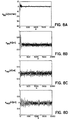
- the following examples are simulated ultrafiltation procedures performed with an ultrafiltration system having adaptive controll and supervisory controll, as described above, wherein either tap water or expired blood functioned as a virtual patient. Since the pump model utilized is based on actual fluid weights or flows and not from pump roller angular speeds, the control performance is independent of the fluid's rheology. While the range of achievable flows may change, the type of fluid used for the simulations is irrelevant from the point of view of flow tracking.
- a sampling period of n 1.75 seconds was used in these examples. This specific sampling period was selected after some initial experimentation, taking into consideration the fact that the instantaneous pump flow is impulsive and only the average flow is of interest. Too small a sampling period may give large variations in flow from sample to sample, resulting in a control signal that varies too rapidly, causing a non-smooth operation. On the other hand, a sampling time of more than a few seconds may result in slow response and large tracking errors.
- a source of measurement noise for the drained weight is the evaporation of drained fluid, which can be prevented by sealing the drain container.
- Other sources of measurement noise include the swinging of replacement fluid bags due to air drafts, which introduces uncertainty in the weight measurements. Placing the bags and the scales inside an enclosure minimizes this uncertainty and enables the practical use of the scales' accuracy ( ⁇ 0.5 gr) as the sole source of uncertainty in the weight measurements.
- Flow measurements are taken by an ultrasonic flow-probe (Transonic Systems, Inc.) which is calibrated by the manufacturer for the fluid being used. The accuracy of the flow-probe is ⁇ 7% of the measured value, which is a source of blood flow error but not of ultrafiltration error.
- the simulation flow rates for the blood, drain, and replacement pumps are chosen to be consistent with those typically used with a neonate as the patient. Ultrafiltration is beneficial to smaller patients if small flow rates and a small extracorporeal blood line volume are used.
- the type and size of tubing and connectors for the blood line are chosen according to the magnitude of the flow rates needed.
- These components determine the ARMA equation parameters for each pump, which in general will vary in time as the physical characteristics of the components vary over time. Values of adaptive step-size ⁇ 0 , maximum voltage u h , and minimum voltage u l , for purposes of the simulations in the example, are given in Table 2. Table 2 Pump ⁇ 0 u 1 [volts] u h [volts] Drain 0.1 0.6 10.0 Replacement 1 0.1 0.2 10.0 Replacement 2 0.1 0.4 5.0 Blood - 0.3 3.2
- the tracking error goes to zero within thirty seconds, while the voltage remains steady.
- a large negative blood pump tracking error at the beginning of the ultrafiltration procedure is tolerated because the patient will not be adversely affected by a slow blood clearance of a few seconds.
- a large positive tracking error could result in decreased tissue perfusion, and the patient may or may not react adversely to the decrease of nutrients reaching various tissues.
- a transiently large negative error at the beginning of the ultrafiltration procedure is tolerated in exchange for preventing tracking overshoot.
- a ultrafiltration procedure lasting approximately one hour, with the blood flow rate set at 40.0 ml/min, the drain flow rate set to 230.0 ml/hr, and both replacement flow rates set to 100.0 ml/hr simulates an ultrafiltration procedure performed on a neonate.
- Typical flow rate and weight tracking errors of a simulation utilizing water as a substitute for all fluids are shown in Figs. 8A, 8B, 8C and 8D.
- the blood pump tracking error at the beginning of this simulation differs in character from the beginning of the simulation shown in Figs. 7A-7C because the flowmeter low pass filter choices provided by the manufacturer were not identical for this time period in the two simulations. Given the precise duration of the procedure, the expected ultrafiltration was 30.1 ml.
- the ultrafiltration measured by comparing the initial (269.3 ⁇ 0.5 gr) and final weight (241.0 ⁇ 0.5 gr) of the "patient" was 28.3 ⁇ 0.7 gr, which results in a difference of 1.7 ⁇ 0.7 ml from the desired ultrafiltration.
- the expected ultrafiltration measured by comparing the initial and final weights of drain and replacement fluids was 28.4 ⁇ 1.2 ml.
- the controller detects the incongruent weight change and decides, in this case, to discontinue ultrafiltration.
- Figs. 10A, 10B, and 10C show simulated patient data and the desired drain rate for a simulation of ultrafiltration performed on a neonate.
- the patient heart rate and blood pressure are generated with computer software.
- the blood flow rate is set to 40 ml/min, and the replacement rates are both set to 100 ml/min.
- the thresholds for the heart rate are chosen as 90 bpm and 105 bpm, and the thresholds for the blood pressure are chosen as 70 mmHg and 95 mmHg (9.332 and 12.666 kPa).
- the supervisory controller makes a correction due to the high heart rate and waits for a reaction.
- the supervisory controller would wait about 10 minutes before taking any other actions because of a high heart rate.
- the wait is shortened to about 30 seconds.
- the switch logic once again activates FSIA 30 seconds after the first correction since the patient's heart rate remains high.
- the supervisory controller waits 30 more seconds, and the switch logic rechecks R h and P b . This time, the heart rate is high and the blood pressure is low, so the switch logic activates FSIC.
- Figs. 11A, 11B and 11C show a simulation where the heart rate and blood pressure are both low and the user has specified a decrease of ultrafiltration when queried by the supervisory controller.
- the blood flow rate is set to 40 ml/min, and the replacement rates are both set to 100 ml/min.
- the minimum and maximum thresholds for the heart rate are chosen as 90 bpm and 105 bpm, and the minimum and maximum thresholds for the blood pressure are chosen as 70 mmHg and 95 mmHg (9.332 and 12.666 kPa).
- R h and P b are within their normal ranges.
- FSIIB calculates an ultrafiltration rate decrease.
- the switch logic forces FSII to wait 10 seconds (5 minutes for an actual ultrafiltration procedure) before another adjustment is made. Since the patient parameters never return to their respective normal ranges, the supervisory controller lowers the drain rate until the ultrafiltration rate is zero.
- Figs. 12A, 12B and 12C show a simulation where the patient parameters are both high and the user specifies an increase of the ultrafiltration rate.
- the blood flow rate is set to 40 ml/min, and the replacement rates are both set to 100 ml/min.
- the thresholds for the heart rate are chosen as 90 bpm and 105 bpm, and the thresholds for the blood pressure are chosen as 70 mmHg and 95 mmHg (9.332 and 12.666 kPa).
- R h and P b are within their normal ranges.
- the condition for activating FSII is met and the ultrafiltration rate is increased. Since the patient parameters never return to their respective normal ranges, the supervisory controller raises the drain rate until the ultrafiltration rate is 30% above the rate initially given. At this point, the hemofiltrator alerts the user that the maximum ultrafiltration rate has been set as the desired rate.
- Figs. 13A, 13B and 13C present a simulation where the patient is getting well enough to increase the ultrafiltration rate.
- the blood flow rate is set to 40 ml/min, and the replacement rates are both set to 100 ml/min.
- the thresholds for the heart rate are chosen as 90 bpm and 105 bpm, and the thresholds for the blood pressure are chosen as 70 mmHg and 95 mmHg (9.332 and 12.666 kPa).
- R h and P b are within their normal ranges.
- the supervisory controller waits 120 seconds (about 60 minutes in an actual ultrafiltration procedure) to detect transient behavior before increasing the drain pump flow rate. Since the heart rate and the blood pressure return to their normal ranges, no further adjustments are made.
- Figs. 14A, 14B and 14C depict a simulation where the supervisory controller adjusts the ultrafiltration due to a high filtered fraction.
- the patient parameters are both high for an extended period of time and the initial ultrafiltration rate of 132.6 ml/hr is increased to 172.4 ml/hr by increasing the drain rate from 332.6 ml/hr to 372.4 ml/hr.
- the latter flow rate would give a filtered fraction of 22.2% if the blood pumping were held at 40.0 ml/min.
- the blood pump flow rate must be increased to 44.3 ml/min.
- the supervisory control system and the adaptive control system described above are not limited to use in a ultrafiltration procedure, but may find application in other medical systems that employ a pump for transferring a fluid, such as a heart-lung machine. Other suitable medical applications would be apparent to one of ordinary skill in the art.
Abstract
Description
- The present invention is directed to a system of blood filtration, and more particularly supervisory control systems and adaptive control systems for controlling the continuous filtration of fluid and/or soluble waste from the blood of a patient based on one or more monitored patient parameters and fluid flow rates.
- For various reasons, including illness, injury or surgery, patients may require replacement or supplementation of their natural renal function in order to remove excess fluid or fluids containing dissolved waste products from their blood. Several procedures known for this purpose are dialysis, hemodialysis, hemofiltration, hemodiafiltration and ultrafiltration; another related procedure is plasmapheresis. The specific procedure employed depends upon the needs of the particular patient. For example, dialysis is used to remove soluble waste and solvent from blood; hemofiltration is used to remove plasma water from blood; hemodiafiltration is used to remove both unwanted solute (soluble waste) and plasma water from blood; ultrafiltration is a species of hemofiltration; and plasmapheresis is used to remove blood plasma by means of a plasmapheresis filter. Because the replacement of renal function may affect nutrition, erythropoiesis, calcium-phosphorus balance and solvent and solute clearance from the patient, it is imperative that there be accurate control of the procedure utilized. The accurate control of the rate of removal of intravascular fluid volume is also important to maintain proper fluid balance in the patient and prevent hypotension.
- Various systems have been proposed to monitor and control renal replacement procedures. For example, U.S. Patent No. 4,132,644 discloses a dialysis system in which the weight of dialyzing liquid in a closed liquid container is indicated by a scale. After the dialyzing liquid flows through the dialyzer, the spent liquid is returned to the same container and the weight is again indicated. Since the container receives the original dialyzing liquid plus ultrafiltrate, the amount of ultrafiltrate removed from the patient is equal to the increase in total weight in the container. This system is not driven by a weight measuring device and does not offer precise control of the amount of liquids used in the procedure.
- U.S. Patent No. 4,204,957 discloses an artificial kidney system which utilizes weight measurement to control the supply of substitute fluid to a patient. In this system, the patient's blood is pumped through a filter and the filtrate from the blood is discharged to a measuring vessel associated with a weighing device. A second measuring vessel containing substitute fluid is associated with a second weighing device and is connected to the purified blood line. By means of a pump, the substitute fluid and the purified blood are pumped back to the patient. The first and second weighing devices are coupled to one another by a measuring system in such a way that a fixed proportion of substitute is supplied to the purified blood stream from the second measuring vessel depending an the weight of the filtrate received in the first measuring vessel. This system does not utilize circulating dialysate fluid in the blood filtration.
- U.S. Patent No. 4,767,399 discloses a system for performing continuous arteriovenous hemofiltration (CAVH). The disclosed system relies upon utilizing a volumetric pump to withdraw a desired amount of fluid from the patient's blood and return a selected amount of fluid volume to the patient.
- U.S. Patent No. 4,923,598 discloses an apparatus for hemodialysis and hemofiltration which comprises an extracorporeal blood circuit including a dialyzer and/or filter arrangement. The system determines fluid withdrawal per unit time and total amount of fluid withdrawn by utilizing flow sensors in conjunction with an evaluating unit located upstream and downstream of the dialyzer or filter arrangement in the blood circuit.
- U.S. Patent No. 4,728,433 discloses a system for regulating ultrafiltration by differential weighing. The system includes a differential weighing receptacle having an inlet chamber and an outlet chamber which allows a fixed amount of fresh dialysate, by weight, to flow through the hemodialyzer. This system operates in a sequence of weighing cycles during which the amount of ultrafiltrate removed from the blood may be calculated. Additionally, the ultrafiltration rate for each weighing cycle may be calculated. This system provides a mechanism for determining and regulating the amount of ultrafiltrate removed from the blood while delivering dialysate to the patient in alternating fill and drain cycles of the inlet and outlet chambers of the differential weighing receptacle.
- For certain patients, renal replacement procedures may extend over hours or even days. In general, current systems for monitoring and controlling renal replacement procedures lack the flexibility and accuracy required to perform such procedures on neonates. This is mainly due to the absence of a satisfactory automatic control of the pumps employed. Because of the patient risk involved in using such equipment, health care personnel measure the fluid removed from the patient on an hourly basis. The continuing need to monitor the fluid removed leads to a significant increase in nursing care and thus increases the cost of the therapy. Therefore, there is a need to improve the level of autonomy for the systems such that the procedure is less time consuming for medical personnel, and consequently less costly. However, the enhanced autonomy must not come at the expense of patient safety.
- Some conventional renal function replacement/supplementation systems possess an elementary level of supervisory control that simply detects the presence of a fault condition, sounds an alarm, and de-energizes the system pumps to halt the procedure. If the hemofilter clots while the pumps are de-energized, the tubing and hemofilter must be replaced with a concomitant increase in the chance of infection for the patient. Furthermore, the hemofiltration procedure is delayed with a possibly negative impact upon the patient's health.
- Due to the time-varying nature of the renal function replacement/supplementation system, the dynamics of fluid pumping may change over time. For example, the characteristics of system components such as tubing, filter, and connectors may vary slowly over time due to aging or as occlusion of the path for fluid flow. As the flow path becomes constricted, the pumping rate of the pump must be altered to compensate for the increased flow resistance. Furthermore, the replacement of a tubing set requires a rapid change adjustment of the pumping rates that may be difficult to initially establish as a relatively constant value due to short-term transient variations. Current systems for monitoring and controlling renal replacement procedures lack the ability to autonomously correct these time-dependent flow rate variations with high accuracy, rapid response, and minimal overshoot or transient variations following correction.
- The need exists for a multipurpose renal function replacement/supplementation system which is accurate, reliable, capable of continuous, long-term operation, and which can be used effectively on adult, pediatric and neonatal patients. Further, the need exists for a feedback control system for controlling the multipurpose renal function replacement/supplementation system that accurately regulates the transfer of fluid and monitors the overall behavior of the system to improve patient care and provide greater autonomy.
- WO93/06875 describes a continuous hemofiltration system, a first reservoir for maintaining a supply of infusate, a first weighing means for monitoring the weight of the infusate and generating signals correlated thereto, first pumping means for pumping the infusate from the first reservoir to hemofiltration means, a second reservoir for receiving drained fluid from the hemofiltration means, a second weighing means for monitoring the weight of the drained fluid and generating signals correlated thereto, and second pumping means for pumping the drained fluid from the hemofiltration means to the second reservoir. The system has control means operably connected to each of the first and second pumping means and the first and second weighing means, the control means being responsive to the signals generated by the first and second weighing means and determining the .weight of infusate and drained fluid in said first and second reservoirs, respectively, at regular intervals, comparing those weights to corresponding predetermined computed weights and adjusting the rates of pumping the infusate and drained fluid so as to remove a preselected amount of fluid from the blood over a preselected time period.
- ASA10 Journal 40 (1994), M686-M690 proposes a fuzzy logic based procedure for controlling the behaviour of a patient's blood pressure during dialysis. A fuzzy control is used to control monitored blood pressure and blood volume to reference values by mathematically translating empirical measures and adjusting ultra filtration rates and dialysate concentration.
- The present invention is directed to a control system for a medical system having at least one pump for pumping fluid, the control system comprising a sensor for measuring the flow rate of fluid in a medical system generated by at least one pump, the flow rate sensor providing flow rate data signals correlated to the fluid flow rate, and a controller operably connectable to the at least one pump in a medical system and operably connected to the flow rate sensor, the controller receiving the flow rate data signals and the controller providing an output signal for the at least one pump to adjust, as necessary on a periodic ongoing basis, the flow rate of fluid generated by the at least one pump, characterised in that the control system further comprises at least one monitor for measuring at least one predetermined patient parameter; said least one patient parameter monitor providing patient parameter data signals correlated to said at least one patient parameter, in that the controller is a supervisory controller which is also operably connected to said at least one patient parameter monitor; in that the controller also receives the patient parameter data signals, and in that the controller analyses the received signals utilising fuzzy logic based on at least one predetermined supervisory rule, and then provides the output signal:
- The control system is preferably employed for a multipurpose system for removal of fluid and/or soluble waste from the blood of a patient: ultrafiltration only, hemodiafiltration, hemodiafiltration and ultrafiltration, hemodialysis, and plasmapheresis with or without fluid replacement. The system can provide reliable, long term operation (5-10 days) with a great degree of accuracy (on the order of ± grams regardless of the total volume of fluid passing through the system). The combination is advantageous because of the multipurpose nature thereof, the repeatability and accuracy of the processes, and the simultaneous, continuous flow of fluids in an extracorporeal blood circuit, while being equally applicable to adult, pediatric and neonatal patients.
- As used herein the term "hemofiltration" is to be broadly construed to include hemodialysis, hemofiltration, hemodiafiltration, ultrafiltration and plasmapheresis processes. As used herein, the term "infusate" is defined to include dialysate fluid or any other replacement fluids which may be supplied to the patient as a part of the hemofiltration procedures.
- In a preferred embodiment, the system of the present invention includes a hemofilter, a blood pump for pumping blood from a patient through the hemofilter and back to the patient, and suitable tubing for carrying the pumped blood to and from the patent. The system further includes a first reservoir for maintaining a supply of infusate, a first weighing means for continuously monitoring the weight of the infusate and generating weight data signals correlated to the monitored weight, and a first pump for pumping the infusate from the first reservoir to the hemofilter or appropriate blood tubing access port. A second reservoir receives drained fluid (e.g., spent infusate or ultrafiltrate, including the fluids and solutes removed from the blood) from the hemofilter, and a second weighing means monitors the weight of the drained fluid and generates weight data signals correlated to the monitored weight. A second pump pumps the drained fluid from the hemofilter to the second reservoir. The system also includes a computerized controller operably connected to the blood pump, the infusate pump, the drain pump and the first and second weighing means.
- The computer controller is, by initial selection of the operator, interfaced with one or more of the various monitoring systems that are operably connected to the patient. These monitoring systems, which are well known in the art, generate and output data signals corresponding to the monitored patient parameters, and the computer controller receives such data signals. During the hemofiltration operation, the interfaced parameters are constantly monitored; however, the controller only responds to specific parameter data that corresponds to the patient parameters selected by the operator. The patient parameters which may be monitored and interfaced with the computer controller include the following: arterial pressure, central venous pressure, pulmonary arterial pressure, mean arterial pressure, capillary wedge pressure, systemic vascular resistance, cardiac output, O2 and CO2 content and saturation (expired, venous or arterial), blood pressure, heart rate, patient weight, external infusion rates, and hematocrit. Numerous of these parameters may be monitored and corresponding output data signals generated in known manner utilizing an indwelling intravenous or intra-arterial catheter. The remaining parameters are monitored and data signals are generated by means well known in the art. The operator will select one or more of the above parameters to interface with the controller which will then periodically, but on an ongoing basis during treatment, interrogate at predetermined intervals the parameter data signals that are continuously generated by the interfaced monitoring system(s). The controller then evaluates the parameter data and in response thereto, when necessary, the controller generates control signals which automatically adjust the pumping rates of the infusate, drained fluid and blood pumps so as to achieve a preselected amount of fluid removal from the patient's blood for patient benefit and safety.
- It will be appreciated that the system of the present invention may utilize a combination of monitoring and responding to the infusate and drained fluid weight data signals along with one or more of the other patient parameters interfaced to the controller.
- By way of specific examples, in connection with monitoring the patient's weight, the computer controller may be interfaced with a bed scale which provides continuous values for the patient's weight. In response to the overall patient weight data signals, the computer controller may control the infusate and/or drained fluid pumps to achieve a predesigned protocol for decreasing or increasing the patient's weight over time. The increase or decrease in patient's weight can be accomplished in either a linear or non-linear manner with respect to time by appropriate pump control. Similarly, the computer may be interfaced with a continuous read-out device of the patient's O2 saturation and the controller will receive, evaluate and respond to the O2 saturation data by controlling the infusate, drained fluid and blood pumping rates accordingly to optimize patient oxygenation.
- In connection with all of the above-described monitored parameters, the computer controller will receive data signals corresponding and relating to each particular selected parameter from an appropriate signal generating device or source operably connected to the patient. The controller will then, after periodic interrogation, compare the interrogated values with predetermined desired values and will automatically make the appropriate, predetermined changes in the infusate, drained fluid and blood pumping rates in response to the monitored signals. Furthermore, more than one of the above-referenced parameters can be continuously monitored simultaneously and the computer may be programmed with a hierarchy to consider one or more specific parameters rather than others and will respond with the appropriate and desired adjustments in infusate, drained fluid and blood pumping rates based on those selected parameters.
- The computer controller is designed and programmed to adjust the pumping rates (pump speed) of the infusate, drained fluid and blood pumps so as to provide a linear response or a non-linear (curvilinear) response to the observed changes in the selected monitored parameters. In this regard, "linear" is defined to mean a fixed, non-exponential change, and "non-linear" or "curvilinear" means anything other than linear. The selection of linear versus non-linear response profile is made by the operator of the system depending on the needs of the patient. For example, in certain situations it may be desirable to have an initially fast fluid removal rate that decreases over time. In that case a curvilinear or exponential response would be utilized. In other circumstances, consistent or constant fluid removal over time is desired, and so a linear response profile is selected. It is further contemplated that at the election of the operator the computer controller may combine linear and curvilinear response signals so as to tailor the pump rates to achieve a desired response profile. For example, a non-linear initial response period for fast initial fluid removal, followed by a linear response period for ongoing fluid removal at a consistent rate.
- In the combination embodiment, the computer controller incorporates the supervisory control system which is operably connected to one or more of the system infusate, drained fluid and blood pumps for controlling the pumping rates of the respective fluids. The supervisory controller receives and utilizes feedback data signals, correlated with the fluid flow rates, regarding the pumping rate of the blood pump that is provided by a flowmeter and the pumping rate of the infusate and drained fluid pumps from the rate change in weight data signals that is provided by electronic scales. The supervisory controller also receives and utilizes patient parameters derived from patient parameter monitors, such as blood pressure data signals from a blood pressure monitor or heart rate data signals from a heart rate monitor. The supervisory controller analyzes these signals utilizing fuzzy logic, based on at least one predetermined supervisory rule, and furnishes an output signal to the appropriate pump to adjust, as necessary on a periodic ongoing basis, the flow rate of fluid generated by that pump. For example, a set of supervisory rules may decide, based upon whether the heart rate and blood pressure are high, normal, or low, to increase or decrease the ultrafiltration rate, or even to discontinue the procedure due to a fault condition.
- In yet an additional alternative embodiment, the computer controller incorporates an adaptive control system for controlling the pumping rate of at least one of the system infusate, drained fluid and blood pumps. The adaptive controller is operably connected to each pump to be adaptively controlled and to its associated flow rate sensor. The adaptive control system receives flow rate data signals correlated to the fluid flow rate from a sensor, such as a flowmeter or weight scale, measuring the flow rate of fluid generated by the pump being controlled. The adaptive controller calculates a controller parameter vector using an adaptive law to generate a set of controller parameters for correcting time-dependent deviations of the flow rate from a predetermined flow rate. Based on the controller parameters, the adaptive controller then uses a control law to generate an output signal for adjusting the pumping rate of fluid generated by the pump to achieve the predetermined flow rate. Finally, the controller provides the output signal to the pump on a periodic ongoing basis for adjusting the fluid flow rate. In one aspect, the adaptive controller may use parameter projections to limit the range of the output signal for maintaining the pump in a linear regime of pump operation.
- A method is disclosed in which, blood from a patient is pumped through a hemofilter and a supply of infusate, which is maintained in a first reservoir, is pumped from the first reservoir through the hemofilter, countercurrent to the blood. The weight of infusate in the first reservoir is continuously monitored and data signals correlated to that weight are generated. Drained fluid (e.g., spent infusate) is pumped from the hemofilter and is received in a second reservoir. The weight of the drained fluid in the second reservoir is continuously monitored and weight data signals correlated thereto are generated. The signals correlated to the weight of infusate and drained fluid are interrogated at regular intervals (for example every minute) by a system controller and are compared to corresponding predetermined computed weights in the memory of the controller. The controller determines the amount and rate of fluid withdrawal from the patient's blood. If those values differ from preselected, preprogrammed desired values, the controller generates control signals which independently adjust the pumping rates of the infusate and drained fluid pumps so as to achieve the desired amount of fluid removal. The control signals may also control the blood pumping rate.
- In an alternative method, independent of or in addition to the infusate and drained fluid weight monitoring and pump control, the computer controller may be interfaced with one or more of the previously discussed monitoring systems. In this method, the controller will receive, evaluate and respond to the selected patient parameter data by generating appropriate, responsive control signals by which the infusate, drained fluid and blood pumping rates are controlled to achieve the desired amount of fluid removal. This may be accomplished in combination with or independent of the infusate and drained fluid weight monitoring.
- In an alternative mode of operation, flow rate data signals for the fluid flow generated by a pump in a hemofiltration system and patient parameter data signals, such as heart rate and blood pressure, are supplied to a supervisory controller. Flow rate data signals are derived from the rate change in weight of either infusate or drained fluid or from the blood flow rate. The signals are analyzed utilizing fuzzy logic based on at least one predetermined supervisory rule and an output signal is provided to the appropriate pump to adjust, as necessary on a periodic ongoing basis, the flow rate of fluid generated by that pump.
- In yet another alternative mode of operation, flow rate data signals for the fluid flow generated by a pump in a hemofiltration system are supplied to an adaptive controller. Flow rate data signals are derived from the rate change in weight of either infusate or drained fluid or from the blood flow rate. A set of controller parameters is generated from the flow rate signals for use in correcting time-dependent deviations in flow rate from a predetermined flow rate. The signals and parameters are analyzed using a control law to generate an output signal. The output signal is provided to the adaptively controlled pump on a periodic ongoing basis.
- The advantages of the system of the present invention are achieved at least in part due to the supervisory system controller and adaptive system controller which implement closed-loop, feedback control systems that precisely and accurately adjust and control pumping rates. Further features and advantages of the system and apparatus of the present invention will become apparent with reference to the Figure and the detailed description which follows.
-
- Fig. 1 is a diagrammatic representation of one embodiment of the system of the present invention; a variation is shown in phantom.
- Fig. 2 is a diagrammatic representation of an alternative embodiment of the system of the present invention.
- Fig.3 diagrammatically illustrates the hierarchical control architecture for a hemofiltration system.
- Fig. 4 diagrammatically illustrates the fuzzy logic process performed by the supervisory controller of Fig. 3.
- Fig. 5 represents the supervisory control architecture implemented in the supervisory controller.
- Fig. 6A is a set of membership functions for blood pressure data signals that are input into the fuzzy logic control system.
- Fig. 6B is a set of input membership functions for heart rate data signals that are input into the fuzzy logic control system.
- Fig. 6C is a set of output membership functions for signals representing changes in ultrafiltration rate that are output from the fuzzy logic control system.
- Fig. 7A is a graphical representation of the tracking error of a blood pump for an ultrafiltration simulation.
- Fig. 7B is a graphical representation of the control voltage for an ultrafiltration simulation.
- Fig. 7C is a graphical representation of the controller parameters for an ultrafiltration simulation.
- Fig. 8A is a graphical representation of the tracking error of a blood pump for an ultrafiltration simulation.
- Fig. 8B is a graphical representation of the tracking error of a drain pump for an ultrafiltration simulation.
- Fig. 8C is a graphical representation of the tracking error of a first replacement pump for an ultrafiltration simulation.
- Fig. 8D is a graphical representation of the tracking error of a second replacement pump for an ultrafiltration simulation.
- Fig. 9A is a graphical representation of the tracking error of a drain pump for an ultrafiltration simulation.
- Fig. 9B is a graphical representation of the control voltage for an ultrafiltration simulation.
- Fig. 9C is a graphical representation of the controller parameters for an ultrafiltration simulation.
- Fig. 10A is a graphical representation of the heart rate for an ultrafiltration simulation.
- Fig. 10B is a graphical representation of the blood pressure for an ultrafiltration simulation.
- Fig. 10C is a graphical representation of the desired drain flow rate calculated by fuzzy system I for an ultrafiltration simulation.
- Fig. 11A is a graphical representation of the heart rate for an ultrafiltration simulation.
- Fig. 11B is a graphical representation of the blood pressure for an ultrafiltration simulation.
- Fig. 11C is a graphical representation of the desired drain flow rate calculated by fuzzy system II for an ultrafiltration simulation.
- Fig. 12A is a graphical representation of the heart rate for an ultrafiltration simulation.
- Fig. 12B is a graphical representation of the blood pressure for an ultrafiltration simulation.
- Fig. 12C is a graphical representation of the desired drain flow rate calculated by fuzzy system III for an ultrafiltration simulation.
- Fig. 13A is a graphical representation of the heart rate for an ultrafiltration simulation.
- Fig. 13B is a graphical representation of the blood pressure for an ultrafiltration simulation.
- Fig. 13C is a graphical representation of the desired drain flow rate calculated by fuzzy system IV for an ultrafiltration simulation.
- Fig. 14A is a graphical representation of the heart rate for an ultrafiltration simulation.
- Fig. 14B is a graphical representation of the blood pressure for an ultrafiltration simulation.
- Fig. 14C is a graphical representation of the desired drain flow rate calculated by FSIII for an ultrafiltration simulation.
- Fig. 14D is a graphical representation of the blood pump flow rate for an ultrafiltration simulation.
- Fig. 1 shows a diagrammatic representation of a preferred embodiment of the system of the present invention. The portion of Fig. 1 shown in phantom represents an alternative embodiment of the present invention which will be described hereinbelow.
Hemofiltration system 10 is operated and controlled by a suitable controller designated generally as 12.Controller 12 may be a programmable computer having adisplay 13 and is operably connected to various components ofhemofiltration system 10, as will be described in greater detail hereinafter. - In operation, blood is pumped from a patient (not shown), which may be an adult, pediatric or neonatal patient, through a suitable catheter (not shown) and
input tubing 14 by means of ablood pump 16.Blood pump 16, which is preferably of the roller type, is operably connected tocontroller 12 byline 18. One suitable blood pump is the RS-7800 Minipump manufactured by Renal Systems, Minneapolis, MN.Input tubing 14 through which the patient's blood is pumped preferably includes apressure transducer 20 upstream ofpump 16.Pressure transducer 20 is operably connected tocontroller 12 vialine 21. Means are included downstream ofblood pump 16 for accessinginput tubing 14 to enable the injection or infusion of desired fluids, including medications and anticlotting compounds such as heparin, into the patient's blood. The injection or infusion of such fluids to the blood may be accomplished in any suitable manner; Fig. 1 shows diagrammatically a syringe andtube arrangement 22, but it will be appreciated that other means could be employed for the same purpose. - The patient's blood is pumped through
hemofilter 24 byblood pump 16. Filters of the type suitable for use in the system of the present invention are readily available; one example of a suitable hemofilter is the Diafilter manufactured by AMICON, Denvers, MA. Where the present system is used to perform plasmapheresis, a suitable plasmapheresis filter such as the Plasmaflo manufactured by Parker Hannifin, Irvine, CA can be employed. -
Input tubing 14 includes asecond pressure transducer 26 slightly upstream ofhemofilter 24.Pressure transducer 26 is operably connected tocontroller 12 via line 28. The patient's blood exitshemofilter 24, passes throughoutput tubing 30 and is returned to the patient via any suitable means such as a venous catheter arrangement (not shown).Output tubing 30 preferably includes a suitableblood flow detector 31 which verifies that there is blood flow in the system and an air bubble/foam control device such asair bubble clamp 32 to prevent the passage of air bubbles to the patient.Blood flow detector 31 andair bubble clamp 32 may be operably connected (not shown) tocontroller 12 or directly to the pumps to interlock all pumps upon detection of any air bubbles in the blood or upon the cessation of blood flow. A suitable foam-bubble detector is the RS-3220A manufactured by Renal Systems.Output tubing 30 also preferably includes apressure transducer 34 immediately downstream ofhemofilter 24.Pressure transducer 34 is operably connected tocontroller 12 vialine 36. - A
first reservoir 50 maintains a supply of suitable dialysate or other fluid, referred to herein generally asinfusate 52. The infusate-containingreservoir 50 is supported by a weighing device such aselectronic scale 54 which is operably connected tocontroller 12 vialine 56.Infusate 52 is pumped fromreservoir 50 viatubing 58 by means ofinfusate pump 60, which is preferably of the roller variety. A suitable pump for this purpose is a 31/2" Roller Pump manufactured by PEMCO, Cleveland, OH.Infusate pump 60 is operably connected tocontroller 12 vialine 62 and pumps infusate 52 throughhemofilter 24 countercurrent to the blood pumped therethrough. In accordance with known principles,infusate 52 may extract certain components (fluids and/or soluble waste) from the blood passing throughhemofilter 24. The fluid drained fromhemofilter 24 includes spent infusate and the components removed from the blood, which are referred to herein as drained fluid 76. In an alternative embodiment whereinsystem 10 is used as a fluid or plasma replacement system, e.g., to perform plasmapheresis, the infusate (which may be blood plasma) fromreservoir 50 is pumped via tubing 59 (shown in phantom) toblood output tubing 30 or viatubing 59a (also shown in phantom) to inputtubing 14, thereby replacing the fluid volume removed from the blood. In this embodiment, the drained fluid 76 from hemofilter orplasmapheresis filter 24 does not include any spent infusate since the infusate is pumped directly toblood output tubing 30 orinput tubing 14 and supplied to the patient. - The drained fluid 76 is pumped from
hemofilter 24 through outlet tubing 64 by means ofdrain pump 66, which is preferably a roller-type pump, and may be the same asinfusate pump 60.Drain pump 66 is operably connected tocontroller 12 vialine 68. Output tubing 64 preferably includes apressure transducer 70 downstream ofhemofilter 24, but upstream ofdrain pump 66.Pressure transducer 70 is operably connected tocontroller 12 via line 72. Output tubing 64 also preferably includes ablood leak detector 67 which detects the presence of blood in the drained fluid 76, as may occur ifhemofilter 24 ruptures. A suitable blood leak detector is sold by COBE, Lakewood, Co as model 500247000.Blood leak detector 67 may be operably connected (not shown) tocontroller 12 or directly to the pumps to interlock all pumps upon the detection of blood in the drained fluid. Drained fluid 76 pumped fromhemofilter 24 is pumped into a second reservoir 74 which collects the drained fluid. Second reservoir 74 is supported by a weighing device such aselectronic scale 78, which is operably connected tocontroller 12 vialine 80. -
Scales reservoirs 50 and 74, respectively. Those weight data signals are continuously fed tocontroller 12, to which the scales are linked through an interface having a data protocol, such as an RS-232 interface. It will be appreciated that a single scale could be utilized in place of the two scales whereby the weight differential betweenreservoir 50 and 74 is monitored and a corresponding data signal is generated.Pressure transducers hemofiltration system 10 and generate pressure data signals correlated thereto which are fed tocontroller 12. A suitable type of pressure transducer is model number 042-904-10 sold by COBE of Lakewood, CO. When certain predetermined alarm or danger conditions exist in thesystem 10, as represented by the pressure data signals, the controller will either adjust the infusate, drained fluid, or blood pumping rate, or a combination thereof, or will shut the system down entirely. -
Controller 12 is preferably a programmable computer that is capable of sending and receiving signals from auxiliary equipment includingpressure transducers second scales blood pump 16,infusate pump 60, anddrain pump 66. In operation,controller 12 interrogates, at regular intervals, the weight data signals generated by first andsecond scales controller 12 determines the weight of infusate and drained fluid in the first andsecond reservoirs 50 and 74 at that point in time, and compares those weights to corresponding predetermined computed weights which have been programmed into and are stored bycontroller 12. By monitoring the weight of infusate inreservoir 50 and the weight of drained fluid in reservoir 74 at regular intervals, the rate of change of those weights and the rate of hemofiltration can be calculated by the computer portion ofcontroller 12. When the weights deviate from the predetermined computed weights and/or the rate of hemofiltration deviates from a preselected, preprogrammed desired rate,controller 12 generates control signals which control or adjust the rates at whichblood pump 16,infusate pump 60 anddrain pump 66 are operated, as necessary, to adjust the hemofiltration rate to the desired rate, or to stop the pumps when preselected limits have been reached. This is accomplished in a continuous manner; i.e., continuous weight data signal generation, periodic interrogation of those weight data signals and computation of the required weight and/or rate information, comparison to predetermined computed values and automatic adjustment of the pumping rates of the pumps, as necessary, to achieve the desired amount and/or rate of hemofiltration. -
Controller 12 is programmed so that infusate pump 60 anddrain pump 66 are operated only whenblood pump 16 is being operated. In the case when ultrafiltration is being performed, the pumping rate ofdrain pump 66 must equal the pumping rate of infusate pump 60 plus the desired ultrafiltration rate. -
Controller 12 continuously receives pressure data signals frompressure transducers hemofilter 24 exceeds a predetermined upper limit, as monitored specifically bypressure transducers controller 12 may stop the pumps when preselected pressure limits (high or low) are exceeded, as for example may occur if the system tubing becomes occluded or ruptures or if pump occlusion occurs. Finally,controller 12 may signal when the infusate level inreservoir 50 reaches a predetermined lower limit and when the drained fluid level in reservoir 76 reaches a predetermined upper limit.Hemofiltration system 10 may also include suitable blood warmer and infusate warmer devices (not shown) to adjust and/or maintain the blood and infusate temperatures at desired levels. Such devices may also generate alarm signals when the fluid temperatures are outside of preselected limits. -
Display 13 offers updated display of measured and computed parameters such as pressures, pressure differentials, temperatures, flow rates and amounts of infusate, drain and ultrafiltration, and alarm conditions.Controller 12 generates both visual and audible alarms and all the pumps are interlocked to prevent operation thereof under alarm conditions. Users have the option of disabling or unabling the alarms (the audible part of the alarm and its interlock with the pumps) to perform a procedure under close supervision. A printer (not shown) is operably connected (not shown) tocontroller 12 to generate a hard copy of procedural data currently displayed or stored at regular intervals, at the completion of a procedure or at any desired time. -
Hemofiltration system 10 can be operated in one of two modes: 1) a manual mode wherein the pumping rates ofblood pump 16,infusate pump 60 anddrain pump 66 are provided bycontroller 12 when fixed voltages are applied; and 2) an automatic mode wherein the pumps are controlled bycontroller 12 when the desired hemofiltration amount or rate has been programmed into the controller. The automatic mode allows the system to be paused and later continued without losing previously measured and computed data. - Fig. 2 shows a diagrammatic representation of several alternative embodiments of the
hemofiltration system 10 of the present invention. Because of the commonality of many of the system components in Fig. 2 vis-a-vis the system depicted in Fig. 1, like reference numerals are intended to indicate like components. Furthermore, the system components in Figs. 2 operate in the same manner as the corresponding system components shown in Fig. 1 and described hereinabove.Input tubing 14 further includes a flowmeter or flowprobe 27 slightly upstream ofhemofilter 24. Theflow probe 27 is operably connected tocontroller 12 vialine 29. Asuitable flow probe 27 is an ultrasonic flow probe manufactured by Transonic Systems, Inc. Other suitable types of flowmeters include a bearingless rotary flowmeter, a Doppler flowmeter, and a differential electromagnetic flowmeter. - The hemofiltration system of Fig. 2 further includes interfaces between
controller 12 and monitoring systems which generate parameter data signals corresponding to selected patient parameters such asblood gas 100,hematocrit 110,patient heart rate 120,patient blood pressure 130 and numerous other patient parameters (designated generally as 140), which other parameters may be one or more of the following: arterial pressure, central venous pressure, pulmonary arterial pressure, mean arterial pressure, capillary wedge pressure, systemic vascular resistance, cardiac output, end tidal O2 and CO2, core and peripheral body temperature, and patient weight. While theblood gas sensor 100 andhematocrit sensor 110 are shown as being connected to theinput tubing 14, these parameters can also be monitored by means associated directly with the patient rather than viatubing 14. In fact, whereas venous O2 saturation could be measured as indicated, arterial O2 saturation would require the monitor to be located elsewhere. The overall patient weight parameter can be monitored utilizing a standard patient bed scale (not shown) as is well known in the art. - During the hemofiltration procedure, one or more of the various patient parameters will be monitored continuously and the controller will, at the selection of the operator, be responsive to selected parameter data supplied to the controller. The parameter data may be evaluated and responded to by the controller independent of the infusate and drained fluid weight data signals; i.e., the system may operate and respond based on one or more of the selected parameters and not the weight data signals; or the system may respond to a combination of the weight data signals and one or more selected specific parameters.
- One or more independent patient infusion pumps 150 may be interfaced with
computer controller 12 to supply data signals correlated to the infusion to the patient of intravenous fluids, medications, parenteral nutrition and/or blood products. Thecontroller 12 may evaluate this data and make modifications to the infusate, drained fluid and blood pumping rates so as to compensate for the extraneous fluid being delivered to the patient by means of the infusion pumps. In this regard, the overall fluid balance in the patient can be managed concurrent with the hemofiltration procedure. - In an alternative embodiment wherein
system 10 is used to perform an ultrafiltration procedure or hemodialysis procedure, the infusate (which may be one or more replacement fluids such as a calcium replacement fluid or a bicarbonate replacement fluid) fromreservoir 50 is pumped via tubing 59 (shown in phantom) toblood outlet tubing 30 or viatubing 59a (also shown in phantom) to inputtubing 14, thereby offsetting substances and fluid volume removed from the blood. In this embodiment, the drained fluid 76 fromhemofilter 24 does not include any spent infusate since the infusate is pumped directly toblood output tubing 30 and supplied to the patient. In yet another alternative embodiment, a distinct replacement fluid may be provided by a system having more than oneinfusate pump 60. For example,infusate pump 60 may be a first infusate pump for delivering a first replacement fluid toblood outlet tubing 30 via tubing 59 and thesystem 10 may further include a second infusate pump (not shown) for delivering a second replacement fluid toblood outlet tubing 30 via a length of tubing (not shown but similar to tubing 59). - Fig. 3 represents a hierarchal control architecture that may be implemented by the
computer controller 12 of Fig. 2 for controlling the pumping rates in thehemofiltration system 10 to perform an ultrafiltration or hemodialysis procedure, referred to hereinafter collectively as an ultrafiltration procedure. Because of the commonality of many of the system components in Fig. 3, vis-a-vis the system depicted in Figs. 1 and 2, like reference numerals are intended to indicate like components. Furthermore, the system components in Fig. 3 operate in the same manner as the corresponding system components shown in Figs. 1 and 2 and described hereinabove. The heirarchal control architecture disclosed herein is further described in "Intelligent Contol of Continuous Venovenous Hemofiltration," Efrain O. Morales, Master's Thesis, University of Cincinnati, Department of Electrical & Computer Engineering and Computer Science, and in "Hierarchical Adaptive and Supervisory Control of Continuous Venovenous Hemofiltration," Efrain O. Morales, Marios M. Polycarpou, Nat Hemasilpin, and John. J. Bissler, submitted to IEEE Transactions on Control Systems Technology, to be published, both of which are hereby incorporated by reference in their entirety. - Referring to Fig. 3, the
supervisory controller 160 controls ablood pump 16, adrain pump 66, and a pair of infusate pumps 60, namely abicarbonate replacement pump 60a and a calcium replacement pump 60b.Pumps 60a, 60b provide replacement fluids to replace fluid volume removed from the patient during the ultrafiltration procedure. The actual weight ωrep1(n), ωrep2(n) of each replacement fluid supplied to the patient is respectively monitored by an electronic scale 54a, 54b (where each scale is similar toscale 54 shown in Fig. 2) with a frequency of a sample period n. In a typical ultrafiltration procedure, the sample period is on the order of one second. The actual weight ωdra(n) of the drained fluid is monitored by anelectronic scale 78. The ultrafiltration rate is calculated as the difference between the rate change in drained fluid weight and the rate change in the replacement fluid weight. The actual flow qblo(n) fromblood pump 16 is indicated by aflow probe 27. -
Blood pump 16 is controlled by anadaptive pump controller 162, implemented in thecontroller 12, which receives a desired fluid flow rate
supervisory controller 160 as a reference command input. Thepump controller 162 is operably connected to theblood pump 16 vialine 18 for transmitting a voltage ublo(n) which corresponds to the desired pumping rate and which is proportional to
flow probe 27 is provided as a feedback signal vialine 29 to thesupervisory controller 160 and to thepump controller 162. Thepump controller 162 further provides a controller parameter vector θblo, indicative of the tracking performance, to thesupervisory controller 160. -
Drain pump 66 is controlled by anadaptive pump controller 170, implemented in thecontroller 12, which receives a desired weight signal
supervisory controller 160 as a reference command input. Thepump controller 170 is operably connected to thedrain pump 66 vialine 68 for transmitting a voltage udra(n) which corresponds to the desired pumping rate and is proportional to the rate change of
scale 78 is provided as a feedback signal vialine 80 to thesupervisory controller 160 and to thepump controller 170. Thepump controller 170 further provides a controller parameter vector θdra, indicative of the tracking performance, to thesupervisory controller 160. -
Bicarbonate replacement pump 60a and calcium replacement pump 60b are controlled by a respectiveadaptive pump controller controller 12, which receives a desired weight signal

supervisory controller 160 as a reference command input. Thepump controller 162 is operably connected via arespective line line 62 shown in Fig. 2) to therespective pump 60a, 60b for transmitting a respective voltage urep1(n), urep2(n) which corresponds to the desired pumping rate and is proportional to the rate change of

supervisory controller 160 and to therespective pump controller pump controller supervisory controller 160. - The
supervisory controller 160 uses a parameter projection feature to remove an input saturation nonlinearity, such that thepumps pump controllers - If the respective applied voltage udra(n), urep1(n), urep2(n) is limited to the linear regime of pump operation, the replacement pumps 60a, 60b and the
drain pump 66 are each adequately modeled by a time-varying auto-regressive moving average (ARMA) adaptive control algorithm. The adaptive control algorithm can be expressed as:
that relates the actual weights ωdra(n), ωrep1(n), ωrep2(n) and the corresponding applied voltages udra(n), urep1(n), urep2(n). A unique set of respective system parameters


pump 


- Employing a direct adaptive control scheme, designed to track the desired weight signal ω*(n), the control voltage is determined from:


where θ(n) is a vector whose components are the controller parameters generated by an adaptive law and φ(n) is a regressor vector, where |φ(n)| ≥ 1 for all n ≥ 0. If e(n) := ω(n) - ω·(n) denotes the tracking error for the accumulated fluid weight, then the tracking error satisfies:
where θ* represents the unknown "optimal" parameter vector
- Although the dependence of θ* on sample time n is not explicit, θ* will vary slowly with time, which is one of the main motivations for the utilization of on-line parameter estimation and adaptive control techniques. In general, the derivation of provably stable adaptive control algorithms for linear time-varying systems is complex. Due to the slowly time-varying nature of the pump dynamics, standard adaptive control methods with θ* constant were found to be satisfactory for the present invention.
- Pumps in an ultrafiltration system typically exhibit saturation behavior at the lower and upper end of the operation. Specifically, below a certain voltage level the rollers of the pump cease to rotate and fluid flow ceases. Similarly, there is a maximum allowable control voltage, typically specified by the pump manufacturer. Due to saturation in the control signal for pumps, the standard adaptive control must be modified such that the inequality u1 ≤ θT(n)φ(n)≤ uh holds, where the positive constants u1 and uh are, respectively, the minimum and maximum allowable control voltages. To address the time-varying parametric uncertainty and input saturations, the following normalized gradient adaptive law with planar projections apply:


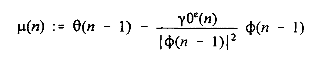
where adaptive step-size γ0 is chosen such that it satisfies


The projection term p(n) guarantees that the controller parameters θ(n) will be projected onto the hyperplane θTφ(n-1) -u1 = 0 if µT(n)φ(n-1) < u1. Similarly, the controller parameters θ(n) will be projected onto the hyperplane θTφ(n-1) -uh = 0 if µT(n)φ(n-1) > uh. Thus the parameter estimates θ(n) are adapted such that the control voltage is restricted to a value between ul and uh. - If the applied voltage ublo(n) is limited to the linear regime of pump operation, the
blood pump 16 is adequately modeled by on ARMA adaptive control algorithm, that may be expressed as:


- A minimum applied voltage is chosen as a value slightly above the voltage for which the rollers of the
blood pump 16 can overcome friction and rotate. If the applied voltage never falls below the minimum voltage, the blood flow is never static during the ultrafiltration procedure and the possibility of clotting is reduced. The minimum voltage will depend upon the properties of the tubing used. A typical minimum voltage is 0.3 volts. A maximum voltage will be provided by the pump manufacturer. A typical maximum voltage is 3.2 volts. - The control law is expressed by


The desired fluid flow

which provides a smooth response to required changes in the desired flow rate. For example, theblood pump 16 start-up will be smooth so that the catheter will not draw against the vessel wall. - Fig. 4 generically illustrates the fuzzy logic process that may be implemented in a microprocessor, such as by
supervisory controller 160 implemented incomputer controller 12, for decision-making to control a process, such as an ultrafiltration procedure. As is familiar from fuzzy logic theory, a fuzzylogic control system 190 generally comprises afuzzifier 192, aninference engine 194, and adefuzzifier 196 for controlling aplant 198. Thefuzzifier 192 accepts one or more discrete input data signals 200 and forms a fuzzy set by assigning degrees of membership in a set of input membership functions. Theinference engine 194 makes one or more fuzzy inferences from the input signals 200 based on afuzzy rule base 202. Thedefuzzifier 196 defuzzifies the fuzzy inferences based upon a set of output membership functions and provides a discreteoutput control signal 204 to theplant 198. Thefuzzy rule base 202 comprises expert knowledge regarding the operational protocol of the system being controlled and comprises sets of "if-then" rules for controlling theplant 198. Thedefuzzifier 196 may apply various mathematical techniques known in the art of fuzzy logic to defuzzify the fuzzy inferences. Theplant 198 may supply feedback signals 206, relating to performance of theplant 198, to the fuzzylogic control system 190 for use by theinference engine 194. - Fuzzification and defuzzification compose the interface needed between measured physical quantities (
inputs 200 and outputs 204) and thefuzzy inference engine 194. The resulting mathematical relation is a fuzzy system. The fuzzy system accepts as inputs crisp values, forms fuzzy sets from these values, makes an inference from the specifiedrule base 202, and provides a crisp output by defuzzifying the inferred fuzzy output. - In the present invention, the plant 168 is the
hemofiltration system 10, the fuzzylogic control system 190 is implemented by software in thecomputer controller 12 for controlling thepumps patient heart rate 120 and thepatient blood pressure 130. Thepatient heart rate 120 is typically measured in beats per minute (bpm) and thepatient blood pressure 130 is typically measured in millimeters of mercury (mmHg). Relying upon the expert clinical knowledge of a physician, an exemplaryfuzzy rule base 202 for modifying the ultrafiltration rate based upon the heart rate 120 (Rh) and the blood pressure 130 (Pb) has the following set of Supervisory Rules: - Supervisory Rule (1):
- If Rh is high and Pb is normal or low, then decrease ultrafiltration. Wait 10 minutes.
- Supervisory Rule (2):
- If Pb is low and Rh is normal or high, then decrease ultrafiltration. Wait 10 minutes.
- Supervisory Rule (3):
- If both Pb and Rh are low then provide the user with a choice between a decrease or increase of the ultrafiltration rate. Wait 5 minutes.
- Supervisory Rule (4):
- If both Pb and Rh are high for 30 consecutive minutes, then provide the user with a choice between a decrease or increase of the ultrafiltration rate.
- Supervisory Rule (5):
- If Pb is high and Rh is low for 60 consecutive minutes, then increase ultrafiltration.
- Supervisory Rule (6):
- The lowest possible value of ultrafiltration is 0 ml./hr. The highest possible value of the ultrafiltration rate is 30% above that of the ultrafiltration rate specified by the physician, and can thus be changed during the ultrafiltration procedure if so desired.
- Supervisory Rule (7):
- If an increase in ultrafiltration occurs such that the filtered fraction (proportional to the ratio of the desired drained rate to the desired blood flow rate) is greater than 20%, increase the blood pump flow such that the filtered fraction equals 0.2.
- Supervisory Rules 1-5 were implemented using fuzzy logic techniques while Supervisory Rules 6 and 7 were incorporated into the supervisory algorithm based on standard switching (crisp) logic methods. The instructions to wait in Supervisory Rules 1-5 are local to each rule. For example, if the ultrafiltration is decreased because Supervisory Rule 1 is satisfied, Supervisory Rule 1 cannot operate again until 10 minutes have lapsed. However, the ultrafiltration rate may be modified if one of Supervisory Rules 2-7 is subsequently triggered. Other sets of Supervisory Rules would be apparent to one of ordinary skill in the art and the Supervisory Rules may be so varied without departing from the scope and spirit of the present invention. For example, a time-independent set of Supervisory Rules is formulated below.
- High and low thresholds of heart rate (Rhigh, Rlow) and blood pressure (Phigh, Plow) are specified to the
supervisory controller 160 based on the size and cardiovascular state of the patient. These thresholds are used by thesupervisory controller 160 to characterize the magnitudes of theheart rate 120 and theblood pressure 130 according to the following inequalities. If Rlow<Rh<Rhigh, then theheart rate 120 is deemed normal. If Rlow>Rh, then theheart rate 120 is characterized as being low, and if Rh>Rhigh then theheart rate 120 is high. Similar inequalities apply to characterize theblood pressure 130. The thresholds may be changed during the ultrafiltration procedure to respond to changes in the patient's cardiovascular state. - Fig. 5 diagrammatically illustrates the
supervisory controller 160 according to the principles of the present invention in which time has been eliminated as an input parameter. Thesupervisory controller 160 comprises four separatefuzzy systems switch logic 250 activates based upon whether theheart rate 120 andblood pressure 130 are low, normal, or high. Only one of thefuzzy systems switch logic 250 also performs the operation of waiting the required duration before or after a supervisory adjustment to the ultrafiltration as required by the Supervisor Rules. - Figs. 6A and 6B are two sets of input membership functions defined for the input data signals of
heart rate 120 andblood pressure 130, respectively, provided to thesupervisory controller 160. Fig. 6C is a set of output membership functions defined for the output data signal connoting thechange 135 in ultrafiltration rate for use in defuzzifying the fuzzy inferences made byfuzzy systems output control signal 135 belongs to a particular fuzzy region. Due to overlaps, one input data signal 120, 130 or output data signal 135 may belong to more than one membership function. The membership functions may be varied to have differing gradations as understood by one of ordinary skill in the art of fuzzy logic. - Each individual input membership function and output membership function is defined as a distinct curve having a center and a full-width. In the example of this description, individual membership functions are chosen from curves having characteristic shapes such as a triangular (T) function, a right trapezoidal (RT) function, a left trapezoidal (LT) function, or a constant value (C) function. Alternative characteristic shapes could be selected depending upon the desired response without departing from the spirit and scope of the present invention.
- With reference to Figs. 6A-C, Table 1 summarizes the input and output membership functions for the following universe of discourse:


where
supervisory controller 160 is activated.Table 1 Name Defined in Type Centroid Width 
U, RT 


U1 T 


U1 T 


U2 C 


U3 T 


U3 T 


U3 LT 


V1 RT 


V1 T 


V1 T 


V2 C 


V3 T 


V3 T 


V3 LT 


Y1 T 


Y1 T 


Y1 T 


Y2 T 


Y2 T 


Y2 T 

- The inputs to the fuzzy systems are the patient heart rate and blood pressure. The output of each
fuzzy system change 135 to the ultrafiltration rate. The change is implemented by keeping the replacement fluid flows constant and adding Δ(n) to the drain flow rate. That is, once a change in ultrafiltration Δ(n) is calculated at sample time n, it is applied as follows:


resulting in an ultrafiltration rate changed by Δ(n) between sample time n and sample time n + 1. The output membership functions may change from sample time to sample time because they are dependent on
- Fuzzy system 210 (FSI) applies where the
heart rate 120 is high and/or theblood pressure 130 is low, as defined in Supervisory Rules 1 and 2, to output a negative number to add to the ultrafiltration rate.Fuzzy system 210 comprises threefuzzy subsystems switch logic 250 activatesfuzzy system 210 if theheart rate 120 is high and theblood pressure 130 is high or low, or if theheart rate 120 is high or low and theblood pressure 130 is low. Theswitch logic 250 also disables the selection offuzzy system 210 for 10 minutes and chooses whichfuzzy subsystem - The
switch logic 250 activatesfuzzy subsystem 210a if Rh is high and Pb is normal. The fuzzy rule base forfuzzy subsystem 210a is: - FSIA Rule (1): If Rh is


- FSIA Rule (2): If Rh is


- FSIA Rule (3): If Rh is


- FSIB Rule (1): If Pb is


- FSIB Rule (2): If Pb is


- FSIB Rule (3): If Pb is


- FSIC Rule (1,1): If Pb is


- FSIC Rule (1, 2): If Pb is


- FSIC Rule (1,3): If Pb is


- FSIC Rule (2,1): If Pb is


- FSIC Rule (2,2): If Pb is


- FSIC Rule (2,3): If Pb is


- FSIC Rule (3,1): If Pb is


- FSIC Rule (3,2): If Pb is


- FSIC Rule (3,3): If Pb is


- The
switch logic 250 activates fuzzy system 220 (FSII) if theheart rate 120 andblood pressure 130 are low, as defined in Supervisory Rule 3, to calculate thechange 135 in ultrafiltration rate and disablesfuzzy system 220 for 10 minutes.Fuzzy system 220 comprises twofuzzy subsystems 220a, 220b (FSIIA, FSIIB). Since the direction of thechange 135 in ultrafiltration rate is indeterminate, theswitch logic 250 must query the user whether the ultrafiltration rate should be increased or decreased. The user selectsfuzzy subsystem 220a to increase the ultrafiltration rate. The fuzzy rule base forfuzzy subsystem 220a is: - Rule (1): If Rh is


- Rule (2): If Rh is


- Rule (3): If Rh is


- Rule (1): If Pb is


- Rule (2): If Pb is


- Rule (3): If Pb is


- The
switch logic 250 activates fuzzy system 230 (FSIII) if theheart rate 120 andblood pressure 130 are both high for 30 consecutive minutes, as defined in Supervisor Rule 4, to calculate thechange 135 in ultrafiltration rate.Fuzzy system 230 comprises two fuzzy subsystems 230a, 230b (FSIIIA, FSIIIB). Since the direction of thechange 135 in ultrafiltration rate is indeterminate, the user is queried whether the ultrafiltration rate should be increased or decreased. The user manually selects fuzzy subsystem 230a to decrease the ultrafiltration rate. The fuzzy rule base for fuzzy subsystem 230a is: - Rule (1): If Pb is


- Rule (2): If Pb is


- Rule (3): If Pb is


- Rule (1): If Rh is


- Rule (2): If Rh is


- Rule (3): If Rh is


- Finally, fuzzy system 230 (FS IV) calculates increases in ultrafiltration rate as a consequence of improvement in the patient's condition. The switch logic activates
fuzzy system 240 if Rh is low and Pb is high. The fuzzy rule base forfuzzy subsystem 240 is: - Rule (1): If Pb is


- Rule (2): If Pb is


- Rule (3): If Pb is


- In another aspect, the
supervisory control system 160 also validates the measured flow rates by comparing those flow rates with prediction errors based on the pump model. Thesupervisory control system 180 must ignore inaccurate fluid weight measurements, which are the result of, for example, inadvertent bumps to theelectronic scales supervisory control system 160 halts the ultrafiltration procedure and triggers audible and visual alarms. - The prediction error for the
drain pump 66 and theinfusate pump 60 is defined as the difference in the measured accumulated fluid weight and the predicted weight forecast by the pump model. The tracking error is defined as the difference in the predicted fluid weight and the desired fluid weight. For theblood pump 16, fluid flow rates are measured byflow probe 27 and the prediction error and the tracking error are referenced with respect to fluid flow rate. - If, for a given minimum number of consecutive sample periods, the prediction error is greater than a positive constant provided by the pump model and the tracking error is greater than a second positive constant also provided by the pump model, the
supervisory controller 160 triggers a supervisory action. If only the prediction error or only the tracking error is large, the parameter estimates by thesupervisory controller 160 are not yet tuned to thehemofiltration system 10. If both errors are large and are of the same sign, thepumps hemofiltration system 10 are halted. If the prediction error and the tracking error are large and of opposite sign, the parameter estimates by thesupervisory controller 160 are marginally tuned to theundisturbed hemofiltration system 10, and either an inaccurate measurement or a sudden drastic change in the dynamics of thehemofiltration system 10 has likely occurred. A drastic change in the pump dynamics can only be caused by a significant system fault such as a tubing leak. If an inconsistent weight or flow is sensed for anypump supervisory controller 160 disables thehemofiltration system 10 and triggers audible and visual alarms. - Implementation of either or both of the aforementioned adaptive control or supervisory control can increase the autonomy of a hemofiltration system. Various advantages follow from the enhanced autonomy. For example, the continuous monitoring and control reduces medical costs and improves the quality of medical care by reducing the need for intermittent supervision of the ultrafiltration procedure by clinical staff. Further details of the invention will be described in the following examples.
- The following examples are simulated ultrafiltation procedures performed with an ultrafiltration system having adaptive controll and supervisory controll, as described above, wherein either tap water or expired blood functioned as a virtual patient. Since the pump model utilized is based on actual fluid weights or flows and not from pump roller angular speeds, the control performance is independent of the fluid's rheology. While the range of achievable flows may change, the type of fluid used for the simulations is irrelevant from the point of view of flow tracking.
- A sampling period of n=1.75 seconds was used in these examples. This specific sampling period was selected after some initial experimentation, taking into consideration the fact that the instantaneous pump flow is impulsive and only the average flow is of interest. Too small a sampling period may give large variations in flow from sample to sample, resulting in a control signal that varies too rapidly, causing a non-smooth operation. On the other hand, a sampling time of more than a few seconds may result in slow response and large tracking errors.
- At the beginning of the simulation in each example, all tubing segments were primed with water, or 150 mEq/L sodium chloride solution if blood is used in the example, to eliminate air bubbles in the lines. A source of measurement noise for the drained weight is the evaporation of drained fluid, which can be prevented by sealing the drain container. Other sources of measurement noise include the swinging of replacement fluid bags due to air drafts, which introduces uncertainty in the weight measurements. Placing the bags and the scales inside an enclosure minimizes this uncertainty and enables the practical use of the scales' accuracy (±0.5 gr) as the sole source of uncertainty in the weight measurements. Flow measurements are taken by an ultrasonic flow-probe (Transonic Systems, Inc.) which is calibrated by the manufacturer for the fluid being used. The accuracy of the flow-probe is ±7% of the measured value, which is a source of blood flow error but not of ultrafiltration error.
- The simulation flow rates for the blood, drain, and replacement pumps are chosen to be consistent with those typically used with a neonate as the patient. Ultrafiltration is beneficial to smaller patients if small flow rates and a small extracorporeal blood line volume are used. The type and size of tubing and connectors for the blood line are chosen according to the magnitude of the flow rates needed. These components determine the ARMA equation parameters for each pump, which in general will vary in time as the physical characteristics of the components vary over time. Values of adaptive step-size γ0, maximum voltage uh, and minimum voltage ul, for purposes of the simulations in the example, are given in Table 2.
Table 2 Pump γ0 u1 [volts] uh [volts] Drain 0.1 0.6 10.0 Replacement 1 0.1 0.2 10.0 Replacement 2 0.1 0.4 5.0 Blood - 0.3 3.2 - For a ultrafiltration procedure simulated with a container full of blood as the "patient", the tracking error, the control voltage and the controller parameters are shown in Figs. 7A, 7B, and 7C, respectively. The tracking error goes to zero within thirty seconds, while the voltage remains steady. A large negative blood pump tracking error at the beginning of the ultrafiltration procedure is tolerated because the patient will not be adversely affected by a slow blood clearance of a few seconds. A large positive tracking error could result in decreased tissue perfusion, and the patient may or may not react adversely to the decrease of nutrients reaching various tissues. Hence, a transiently large negative error at the beginning of the ultrafiltration procedure is tolerated in exchange for preventing tracking overshoot.
- A ultrafiltration procedure lasting approximately one hour, with the blood flow rate set at 40.0 ml/min, the drain flow rate set to 230.0 ml/hr, and both replacement flow rates set to 100.0 ml/hr simulates an ultrafiltration procedure performed on a neonate. Typical flow rate and weight tracking errors of a simulation utilizing water as a substitute for all fluids are shown in Figs. 8A, 8B, 8C and 8D. The blood pump tracking error at the beginning of this simulation differs in character from the beginning of the simulation shown in Figs. 7A-7C because the flowmeter low pass filter choices provided by the manufacturer were not identical for this time period in the two simulations. Given the precise duration of the procedure, the expected ultrafiltration was 30.1 ml. The ultrafiltration measured by comparing the initial (269.3 ± 0.5 gr) and final weight (241.0 ± 0.5 gr) of the "patient" was 28.3 ± 0.7 gr, which results in a difference of 1.7 ± 0.7 ml from the desired ultrafiltration. The expected ultrafiltration measured by comparing the initial and final weights of drain and replacement fluids was 28.4 ± 1.2 ml. The expected ultrafiltration rate is calculated from the initial weights for the drain and replacement containers 0.0 ± 0.5 gr, 345.2 ± 0.5 gr, and 341.3 ± 0.5 gr, respectively, and the corresponding final weights 230.5 ± 0.5 gr, 243.4 ± 0.5 gr, and 241.0 ± 0.5 gr, respectively, as [(230.5 ± 0.5) - (0.0 ± 0.5)] - [345.2 ± 0.5) - (243.4 ± 0.5)] - [341.3 ± 0.5) - (241.0 ± 0.5)] = 28.4 ± 1.2 gr.
- Figs. 9A, 9B, and 9C present a simulation where the scale is bumped twice and a tubing leak occurs. Threshold values for determining an incongruent weight change are given in Table 3.
Table 3 Pump Maximum Tracking Error Maximum Prediction Error Minimum No. of Samples for Validating An Incongruent Measurement of Flow Blood 20 ml/ min 20 mllmin 5 Drain 3 gr 3 gr 5 Replacement 1 3 gr 3 gr 5 Replacement 2 3 gr 3 gr 5
A brief disturbance of a large magnitude is introduced at a n=10 (by placing a large weight on the scale and removing it), and the supervisory controller does not react. At n=60, a similar, smaller disturbance is introduced for a brief period, and again, the supervisory controller does not respond. At n=90, a similar small disturbance is introduced, but for a prolonged period. This simulates a leak in the tubing, and is a much smaller disturbance than is generally encountered when leaks occur during actual ultrafiltration procedures. The controller detects the incongruent weight change and decides, in this case, to discontinue ultrafiltration. - Figs. 10A, 10B, and 10C show simulated patient data and the desired drain rate for a simulation of ultrafiltration performed on a neonate. The patient heart rate and blood pressure are generated with computer software. The blood flow rate is set to 40 ml/min, and the replacement rates are both set to 100 ml/min. The thresholds for the heart rate are chosen as 90 bpm and 105 bpm, and the thresholds for the blood pressure are chosen as 70 mmHg and 95 mmHg (9.332 and 12.666 kPa). At the beginning of the simulation, Rh and Pb are within their normal ranges. Around n=40, Rh rises to above the threshold while Pb stays normal. The supervisory controller makes a correction due to the high heart rate and waits for a reaction. During an actual ultrafiltration procedure, the supervisory controller would wait about 10 minutes before taking any other actions because of a high heart rate. For purposes of the simulation, the wait is shortened to about 30 seconds. The switch logic once again activates
FSIA 30 seconds after the first correction since the patient's heart rate remains high. The supervisory controller waits 30 more seconds, and the switch logic rechecks Rh and Pb. This time, the heart rate is high and the blood pressure is low, so the switch logic activates FSIC. The fuzzy subsystem FISC decreases the ultrafiltration rate at about n=100, and shortly thereafter Rh and Pb begin to return to normal. Since the patient parameters rerum to normal before the supervisory controller checks if the reactivation of FSI is necessary, no further corrections are made. - Figs. 11A, 11B and 11C show a simulation where the heart rate and blood pressure are both low and the user has specified a decrease of ultrafiltration when queried by the supervisory controller. The blood flow rate is set to 40 ml/min, and the replacement rates are both set to 100 ml/min. The minimum and maximum thresholds for the heart rate are chosen as 90 bpm and 105 bpm, and the minimum and maximum thresholds for the blood pressure are chosen as 70 mmHg and 95 mmHg (9.332 and 12.666 kPa). At the beginning of the simulation, Rh and Pb are within their normal ranges. At about n=80, Rh and Pb drop below their respective low thresholds, and FSIIB calculates an ultrafiltration rate decrease. The switch logic forces FSII to wait 10 seconds (5 minutes for an actual ultrafiltration procedure) before another adjustment is made. Since the patient parameters never return to their respective normal ranges, the supervisory controller lowers the drain rate until the ultrafiltration rate is zero.
- Figs. 12A, 12B and 12C show a simulation where the patient parameters are both high and the user specifies an increase of the ultrafiltration rate. The blood flow rate is set to 40 ml/min, and the replacement rates are both set to 100 ml/min. The thresholds for the heart rate are chosen as 90 bpm and 105 bpm, and the thresholds for the blood pressure are chosen as 70 mmHg and 95 mmHg (9.332 and 12.666 kPa). At the beginning of the simulation, Rh and Pb are within their normal ranges. At about n=60, both the patient heart rate and blood pressure rise above their respective upper thresholds. After 20 seconds (30 minutes in an actual ultrafiltration procedure), the condition for activating FSII is met and the ultrafiltration rate is increased. Since the patient parameters never return to their respective normal ranges, the supervisory controller raises the drain rate until the ultrafiltration rate is 30% above the rate initially given. At this point, the hemofiltrator alerts the user that the maximum ultrafiltration rate has been set as the desired rate.
- Figs. 13A, 13B and 13C present a simulation where the patient is getting well enough to increase the ultrafiltration rate. The blood flow rate is set to 40 ml/min, and the replacement rates are both set to 100 ml/min. The thresholds for the heart rate are chosen as 90 bpm and 105 bpm, and the thresholds for the blood pressure are chosen as 70 mmHg and 95 mmHg (9.332 and 12.666 kPa). At the beginning of the simulation, Rh and Pb are within their normal ranges. Once the heart rate and blood pressure are in the favorable regions, the supervisory controller waits 120 seconds (about 60 minutes in an actual ultrafiltration procedure) to detect transient behavior before increasing the drain pump flow rate. Since the heart rate and the blood pressure return to their normal ranges, no further adjustments are made.
- Figs. 14A, 14B and 14C depict a simulation where the supervisory controller adjusts the ultrafiltration due to a high filtered fraction. The patient parameters are both high for an extended period of time and the initial ultrafiltration rate of 132.6 ml/hr is increased to 172.4 ml/hr by increasing the drain rate from 332.6 ml/hr to 372.4 ml/hr. The latter flow rate would give a filtered fraction of 22.2% if the blood pumping were held at 40.0 ml/min. In order to bring the filtered fraction down to 20%, the blood pump flow rate must be increased to 44.3 ml/min.
- The supervisory control system and the adaptive control system described above are not limited to use in a ultrafiltration procedure, but may find application in other medical systems that employ a pump for transferring a fluid, such as a heart-lung machine. Other suitable medical applications would be apparent to one of ordinary skill in the art.
- It will be appreciated by persons skilled in the art that various modifications can be made to the systems and methods of the present invention.
The
The
Alternatively, the user selects fuzzy subsystem 220b to decrease the ultrafiltration rate. The fuzzy rule base for fuzzy subsystem 220b is:
The user selects fuzzy subsystem 230b to increase the ultrafiltration rate. The fuzzy rule base for fuzzy subsystem 230b is:
The
Claims (12)
- A control system (12) for a medical system having at least one pump (16, 60a, 60b, 66, 150) for pumping fluid, the control system comprising a sensor (27, 54a, 54b, 78) for measuring the flow rate of fluid in a medical system generated by at least one pump (16, 60a, 60b, 66, 150), the flow rate sensor (27, 54a, 54b, 78) providing flow rate data signals correlated to the fluid flow rate, and a controller (160) operably connectable to the at least one pump (16, 60a, 60b, 66, 150) in a medical system and operably connected to the flow rate sensor (27, 54a, 54b, 78), the controller (160) receiving the flow rate data signals and the controller providing an output signal for the at least one pump (16, 60a, 60b, 66, 150) to adjust, as necessary on a periodic ongoing basis, the flow rate of fluid generated by the at least one pump, characterised in that the control system further comprises at least one monitor (100, 110, 120, 130, 140) for measuring at least one predetermined patient parameter; said least one patient parameter monitor (100, 110, 120, 130, 140) providing patient parameter data signals correlated to said at least one patient parameter, in that the controller is a supervisory controller (160) which is also operably connected to said at least one patient parameter monitor (100, 110, 120, 130, 140); in that the controller (160) also receives the patient parameter data signals, and in that the controller analyses the received signals utilising fuzzy logic based on at least one predetermined supervisory rule, and then provides the output signal.
- The control system of claim 1, wherein said at least one patient parameter monitor is selected from the group consisting of a blood pressure monitor (130) providing blood pressure data signals, a heart rate monitor (120) providing heart rate data signals, and combinations thereof.
- The control system of claim 2, wherein the medical system is an ultrafiltration system and the at least one predetermined supervisory rule is selected from the group consisting ofa) If heart rate is high and blood pressure is normal or low, then decrease ultrafiltration and wait a first predetermined time.b) If blood pressure is low and heart rate is normal or high, then decrease ultrafiltration and wait a second predetermined time.c) If blood pressure is low and heart rate is low, then provide the user a choice between a decrease or increase of the ultrafiltration rate and wait a third predetermined time.d) If blood pressure is high and heart rate is high for a fourth predetermined time, then provide the user with a choice between a decrease or increase of the ultrafiltration rate.e) If blood pressure is high and heart rate is low for a fifth predetermined time, then increase ultrafiltration.f) The lowest possible value of ultrafiltration is a predetermined minimum rate per hour and the highest possible value of the ultrafiltration rate is a predetermined percentage above that of a predetermined maximum ultrafiltration rate.g) If an increase in ultrafiltration occurs such that the filtered fraction is greater than a predetermined filtered fraction, increase the blood pump flow such that the filtered fraction equals the predetermined filtered fraction.
- The control system of any preceding claim, further comprising a second sensor (27, 54a, 54b, 78) for measuring the flow rate of fluid in a medical system generated by a second pump (16, 60a, 60b, 66, 150), the second flow rate sensor providing second flow rate data signals correlated to the fluid flow rate, wherein the supervisory controller (160) is further operably connectable to the second pump (16, 60a, 60b, 66, 150) and operably connected to the second flow rate sensor (27, 54a, 54b, 78), the controller receiving the second flow rate data signals and analysing the signals utilising fuzzy logic based on at least one predetermined supervisory rule and the controller then providing an output signal for the second pump (16, 60a, 60b, 66, 150) to adjust, as necessary on a periodic ongoing basis, the flow rate of fluid generated by the second pump.
- The control system of claim 4, further comprising a third sensor (27, 54a, 54b, 78) for measuring the flow rate of fluid in a medical system generated by a third pump (16, 60a, 60b, 66, 150), the third flow rate sensor (27, 54a, 54b, 78) providing third flow rate data signals correlated to the fluid flow rate, wherein the supervisory controller (160) is further operably connectable to the third pump (16, 60a, 60b, 66, 150) and operably connected to the third flow rate sensor (27, 54a, 54b, 78), the controller receiving the third flow rate data signals and analysing the signals utilising fuzzy logic based on at least one predetermined supervisory rule and the controller then providing an output signal for the third pump (16, 60a, 60b, 66, 150) to adjust, as necessary on a periodic ongoing basis, the flow rate of fluid generated by the third pump.
- The control system of claim 5, further comprising a fourth sensor (27, 54a, 54b, 78) for measuring the flow rate of fluid in a medical system generated by a fourth pump (16, 60a, 60b, 66, 150), the fourth flow rate sensor (27, 54a, 54b, 78) providing fourth flow rate data signals correlated to the fluid flow rate, wherein the supervisory controller is further operably connectable to the fourth pump (16, 60a, 60b, 66, 150) and operably connected to the fourth flow rate sensor (27, 54a, 54b, 78), the controller receiving the fourth flow rate data signals and analysing the signals utilising fuzzy logic based on at least one predetermined supervisory rule and the controller then providing an output signal to the fourth pump (16, 60a, 60b, 66, 150) to adjust, as necessary on a periodic ongoing basis, the flow rate of fluid generated by the fourth pump.
- The control system of any preceding claim, further comprising an adaptive controller (162, 170, 180a, 180b) operably connectable to the pump (16, 60a, 60b, 66, 150) and to said flow rate sensor (27, 54a, 54b, 78), the adaptive controller (162, 170, 180a: 180b) receiving said flow rate data signals, using an adaptive law to generate a set of controller parameters for correcting time-dependent deviations of the flow rate of the respective fluid from a predetermined blood flow rate, and using a control law to generate an output signal from the set of controller parameters for adjusting the pumping rate of fluid generated by the pump (16, 60a, 60b, 66, 150) to achieve the predetermined blood flow rate, said adaptive controller then providing the output signal for the pump (16, 60a, 60b, 66, 150) on a periodic ongoing basis.
- The control system of any preceding claim, wherein the sensor is selected from the group consisting of a flowmeter (27) and a weight scale (54a, 54b, 78).
- The control system of claim 8, wherein the sensor is a weight scale (54a, 54b, 78) providing weight data signals and the flow rate data signals comprise the rate change in the weight data signals.
- Continuous hemofiltration system for removal of fluid from the blood of a patient, comprising a hemofilter (24), a first pump (16) for pumping blood from a patient through the hemofilter (24) and back to the patient, a first reservoir (50) for maintaining a supply of infusate, a second pump (60) for pumping the infusate from the first reservoir (50) to the hemofilter (24), a second reservoir (74) for receiving drained fluid from the hemofilter (24), a third pump (66) for pumping the drained fluid from the hemofilter (24) to the second reservoir (74), and a control system as claimed in claim 7, wherein the sensor to which the adaptive controller (162, 170, 180a, 180b) is operably connected is a flowmeter (27) downstream of the first pump (16) to measure the blood outflow from the first pump and wherein the adaptive controller (162, 170, 180a, 180b) is operably connected to the first pump (16) and generates an output signal for adjusting the pumping rate of fluid generated by the first pump (16).
- The continuous hemofiltration system of claim 10, wherein the supervisory controller is operably connected to a first scale (54) to measure the weight of infusate in the first reservoir (50), the first scale (54) generating infusate flow rate data signals correlated to the infusate weight, and to a second scale (78) to measure the weight of drained fluid in the second reservoir (74), the second scale (78) generating drained fluid flow rate data signals correlated to the drained fluid weight, and wherein the supervisory controller (160) is operably connected to the at least one pump (16, 60a, 60b, 66, 150).
- Continuous filtration system for removal of fluid from the blood of a patient, comprising a hemofilter (24), a first pump (16) for pumping blood from a patient through the hemofilter and back to the patient, a first reservoir (50) for maintaining a supply of infusate, a second pump (60) for pumping the infusate from the first reservoir (50) to the hemofilter (24), a second reservoir (74) for receiving drained fluid from the hemofilter (24), a third pump (66) for pumping the drained fluid from the hemofilter (24) to the second reservoir (74) and a control system as claimed in any one of claims 1 to 9 wherein the sensor is a flowmeter (27) downstream of the first pump (16) to measure the blood outflow from the first pump, a first scale (54) to measure the weight of infusate in the first reservoir (50), the first scale (54) generating infusate flow rate data signals correlated to the infusate weight and a second scale (78) to measure the weight of drained fluid in the second reservoir (74), the second scale (78) generating drained fluid flow rate data signals correlated to the drained fluid weight and wherein the supervisory controller (160) is operably connected to the pumps (16, 60a, 60b, 66, 150), flow meter (27) and scales (57, 78), the supervisory controller (160) also receiving the infusate flow rate data signals and the drained fluid flow rate data signals, and wherein the supervisory controller (160) provides an output signal to one or more of the pumps (16, 60a, 60b, 66, 150) to adjust, as necessary on a periodic ongoing basis, the flow rate of fluid generated by the one or more of the pumps (16, 60a, 60b, 66, 150).
Priority Applications (1)
| Application Number | Priority Date | Filing Date | Title |
|---|---|---|---|
| EP04078443A EP1514562B1 (en) | 1999-04-30 | 2000-04-28 | Hemofiltration system |
Applications Claiming Priority (3)
| Application Number | Priority Date | Filing Date | Title |
|---|---|---|---|
| US13195599P | 1999-04-30 | 1999-04-30 | |
| US131955P | 1999-04-30 | ||
| PCT/US2000/011620 WO2000066197A1 (en) | 1999-04-30 | 2000-04-28 | Hemofiltration system |
Related Child Applications (1)
| Application Number | Title | Priority Date | Filing Date |
|---|---|---|---|
| EP04078443A Division EP1514562B1 (en) | 1999-04-30 | 2000-04-28 | Hemofiltration system |
Publications (2)
| Publication Number | Publication Date |
|---|---|
| EP1175238A1 EP1175238A1 (en) | 2002-01-30 |
| EP1175238B1 true EP1175238B1 (en) | 2006-01-25 |
Family
ID=22451766
Family Applications (2)
| Application Number | Title | Priority Date | Filing Date |
|---|---|---|---|
| EP04078443A Expired - Lifetime EP1514562B1 (en) | 1999-04-30 | 2000-04-28 | Hemofiltration system |
| EP00928598A Expired - Lifetime EP1175238B1 (en) | 1999-04-30 | 2000-04-28 | Hemofiltration system |
Family Applications Before (1)
| Application Number | Title | Priority Date | Filing Date |
|---|---|---|---|
| EP04078443A Expired - Lifetime EP1514562B1 (en) | 1999-04-30 | 2000-04-28 | Hemofiltration system |
Country Status (10)
| Country | Link |
|---|---|
| US (3) | US6780322B1 (en) |
| EP (2) | EP1514562B1 (en) |
| JP (2) | JP4903311B2 (en) |
| AT (2) | ATE316391T1 (en) |
| AU (1) | AU766427B2 (en) |
| BR (1) | BR0009799B1 (en) |
| CA (1) | CA2368809C (en) |
| DE (2) | DE60042088D1 (en) |
| IL (2) | IL145897A0 (en) |
| WO (1) | WO2000066197A1 (en) |
Cited By (4)
| Publication number | Priority date | Publication date | Assignee | Title |
|---|---|---|---|---|
| CN104199284A (en) * | 2013-02-28 | 2014-12-10 | B·布莱恩·阿维图姆股份公司 | Fuzzy logic |
| US8926542B2 (en) | 2011-04-29 | 2015-01-06 | Medtronic, Inc. | Monitoring fluid volume for patients with renal disease |
| EP3797803A1 (en) * | 2019-09-26 | 2021-03-31 | B. Braun Avitum AG | Blood processing device with improved bag weight monitoring |
| US11850344B2 (en) | 2021-08-11 | 2023-12-26 | Mozarc Medical Us Llc | Gas bubble sensor |
Families Citing this family (170)
| Publication number | Priority date | Publication date | Assignee | Title |
|---|---|---|---|---|
| JP4903311B2 (en) * | 1999-04-30 | 2012-03-28 | チルドレンズ ホスピタル メディカル センター | Hematological filtration system and method based on monitored patient parameters, hemofiltration monitoring and control apparatus and adaptive control of blood filtration pump |
| AU2001274989A1 (en) * | 2000-05-27 | 2001-12-11 | Georgia Tech Research Corporation | Adaptive control system having direct output feedback and related apparatuses and methods |
| ATE380563T1 (en) † | 2000-07-07 | 2007-12-15 | Fresenius Medical Care De Gmbh | HEMODIALYSIS DEVICE |
| US6585675B1 (en) * | 2000-11-02 | 2003-07-01 | Chf Solutions, Inc. | Method and apparatus for blood withdrawal and infusion using a pressure controller |
| WO2002053209A1 (en) * | 2000-12-27 | 2002-07-11 | Philips Japan, Ltd. | Biological information and blood treating device information control system, biological information and blood treating device information control device, and biological information and blood treating device information control method |
| US7393656B2 (en) * | 2001-07-10 | 2008-07-01 | The Board Of Trustees Of The Leland Stanford Junior University | Methods and compositions for risk stratification |
| AU2002365421A1 (en) * | 2001-07-10 | 2003-09-02 | The Board Of Trustees Of The Leland Stanford Junior University | Methods and compositions for detecting the activation state of the multiple proteins in single cells |
| US7381535B2 (en) * | 2002-07-10 | 2008-06-03 | The Board Of Trustees Of The Leland Stanford Junior | Methods and compositions for detecting receptor-ligand interactions in single cells |
| DE10144441A1 (en) * | 2001-09-06 | 2003-03-27 | Biotronik Mess & Therapieg | Fuzzy inference engine |
| SE523610C2 (en) * | 2001-10-02 | 2004-05-04 | Gambro Lundia Ab | Method of controlling dialysis device |
| US7241272B2 (en) | 2001-11-13 | 2007-07-10 | Baxter International Inc. | Method and composition for removing uremic toxins in dialysis processes |
| US20030128125A1 (en) | 2002-01-04 | 2003-07-10 | Burbank Jeffrey H. | Method and apparatus for machine error detection by combining multiple sensor inputs |
| US9717840B2 (en) | 2002-01-04 | 2017-08-01 | Nxstage Medical, Inc. | Method and apparatus for machine error detection by combining multiple sensor inputs |
| US7163520B2 (en) | 2002-06-26 | 2007-01-16 | Chf Solutions, Inc. | Method and device for removal of radiocontrast media from blood |
| EP2298377A1 (en) * | 2002-07-19 | 2011-03-23 | Baxter International Inc. | Systems and methods for peritoneal dialysis |
| DE60336724D1 (en) | 2002-07-19 | 2011-05-26 | Baxter Healthcare Sa | SYSTEM FOR PERITONEAL DIALYSIS |
| US7704454B1 (en) * | 2003-10-08 | 2010-04-27 | Caridianbct, Inc. | Methods and devices for processing blood |
| ITMO20030293A1 (en) * | 2003-10-29 | 2005-04-30 | Gambro Lundia Ab | DEVICE FOR THE DETERMINATION OF THE BLOOD FLOW IN AN EXTRACORPOREO CIRCUIT, AS WELL AS THE EQUIPMENT FOR BLOOD TREATMENT USING THE SAME DEVICE. |
| US8029454B2 (en) * | 2003-11-05 | 2011-10-04 | Baxter International Inc. | High convection home hemodialysis/hemofiltration and sorbent system |
| US20060064053A1 (en) * | 2004-09-17 | 2006-03-23 | Bollish Stephen J | Multichannel coordinated infusion system |
| AU2011203293B2 (en) * | 2004-09-17 | 2011-12-01 | Carefusion 303, Inc. | Multichannel coordinated infusion system |
| WO2006086490A1 (en) | 2005-02-07 | 2006-08-17 | Medtronic, Inc. | Ion imbalance detector |
| DE102005013418A1 (en) * | 2005-03-23 | 2006-09-28 | B. Braun Medizintechnologie Gmbh | Blood treatment device with alarm device |
| JP4726045B2 (en) * | 2005-04-08 | 2011-07-20 | 日機装株式会社 | Hemodialysis machine |
| ITMI20050866A1 (en) * | 2005-05-13 | 2006-11-14 | Marco Ranucci | MONITORING SYSTEM FOR CARDIAC SURGERY INTERVENTIONS WITH CARDIOPOLMONARY BYPASS |
| US7769474B2 (en) * | 2005-09-20 | 2010-08-03 | Honeywell International Inc. | Method for soft-computing supervision of dynamical processes with multiple control objectives |
| JP4968573B2 (en) * | 2005-10-26 | 2012-07-04 | 和之 小川 | Operation method of ultrafiltration device |
| US7785463B2 (en) * | 2006-03-17 | 2010-08-31 | Children's Hospital Medical Center | Extracorporeal renal replacement modeling system |
| US8496809B2 (en) | 2006-06-05 | 2013-07-30 | Baxter International Inc. | Dynamic weight balancing of flow in kidney failure treatment systems |
| JP5390378B2 (en) * | 2006-06-13 | 2014-01-15 | ケアフュージョン 303、インコーポレイテッド | System and method for optimizing the control of PCA and PCEA systems |
| US7887502B2 (en) * | 2006-09-15 | 2011-02-15 | University Of Florida Research Foundation, Inc. | Method for using photoplethysmography to optimize fluid removal during renal replacement therapy by hemodialysis or hemofiltration |
| US10632237B2 (en) * | 2006-10-09 | 2020-04-28 | Minnetronix, Inc. | Tangential flow filter system for the filtration of materials from biologic fluids |
| WO2008053259A1 (en) * | 2006-10-30 | 2008-05-08 | Gambro Lundia Ab | Hemo(dia)filtration apparatus |
| ATE534418T1 (en) * | 2006-10-30 | 2011-12-15 | Gambro Lundia Ab | AIR SEPARATOR FOR EXTRACORPORAL FLUID TREATMENT SETS |
| US8647291B2 (en) * | 2006-10-30 | 2014-02-11 | Gambro Lundia Ab | Extracorporeal blood chamber |
| US7789850B2 (en) * | 2007-01-22 | 2010-09-07 | Baxter International Inc. | Weight controlled dialysis system with accelerometer |
| US20090120864A1 (en) * | 2007-10-05 | 2009-05-14 | Barry Neil Fulkerson | Wearable dialysis methods and devices |
| US8114276B2 (en) | 2007-10-24 | 2012-02-14 | Baxter International Inc. | Personal hemodialysis system |
| US9415150B2 (en) * | 2007-11-09 | 2016-08-16 | Baxter Healthcare S.A. | Balanced flow dialysis machine |
| EP2244662B1 (en) * | 2008-01-28 | 2021-09-29 | Implantica Patent Ltd. | Blood clot removal device and system |
| CN102006896B (en) * | 2008-04-15 | 2014-02-19 | 甘布罗伦迪亚股份公司 | Blood treatment apparatus |
| WO2009134944A2 (en) * | 2008-04-29 | 2009-11-05 | Nodality, Inc. | Methods of determining the health status of an individual |
| US20090291458A1 (en) * | 2008-05-22 | 2009-11-26 | Nodality, Inc. | Method for Determining the Status of an Individual |
| US8057679B2 (en) | 2008-07-09 | 2011-11-15 | Baxter International Inc. | Dialysis system having trending and alert generation |
| WO2010006291A1 (en) * | 2008-07-10 | 2010-01-14 | Nodality, Inc. | Methods for diagnosis, prognosis and treatment |
| CN102089763A (en) * | 2008-07-10 | 2011-06-08 | 伊西康内外科公司 | Medical system which controls delivery of a drug and which includes a backpack pouch |
| US8399206B2 (en) | 2008-07-10 | 2013-03-19 | Nodality, Inc. | Methods for diagnosis, prognosis and methods of treatment |
| US20100099109A1 (en) * | 2008-10-17 | 2010-04-22 | Nodality, Inc., A Delaware Corporation | Methods for Analyzing Drug Response |
| US8182673B2 (en) | 2009-01-29 | 2012-05-22 | Baxter International Inc. | Drain and fill logic for automated peritoneal dialysis |
| US8142649B2 (en) * | 2009-01-29 | 2012-03-27 | Baxter International Inc. | Method for optimizing tidal therapies employing ultrafiltrate trending |
| WO2010104878A1 (en) * | 2009-03-09 | 2010-09-16 | Thermedx Llc | Surgical fluid management system |
| US8282829B2 (en) | 2009-05-20 | 2012-10-09 | Baxter International Inc. | System and method for automated data collection of twenty-four hour ultrafiltration and other patient parameters using wired or wireless technology |
| US9480789B2 (en) * | 2009-06-01 | 2016-11-01 | Ethicon Endo-Surgery, Inc. | Method and sedation delivery system including a pump assembly and a co-formulation of first and second drugs |
| MX337978B (en) | 2009-07-01 | 2016-03-29 | Fresenius Med Care Hldg Inc | Drug delivery devices and related systems and methods. |
| US9242042B2 (en) * | 2009-07-21 | 2016-01-26 | Ethicon Endo-Surgery, Inc. | Drug delivery system including a drug-container holder and a pump assembly |
| US20110017667A1 (en) * | 2009-07-27 | 2011-01-27 | Transvivo Inc. | Modular hemofiltration apparatus and method for carrying out neonatal and pediatric crrt |
| DE102009040049A1 (en) * | 2009-09-03 | 2011-03-10 | Krones Ag | Method for controlling a separation plant with a reverse osmosis element and reverse osmosis system |
| US9399091B2 (en) | 2009-09-30 | 2016-07-26 | Medtronic, Inc. | System and method to regulate ultrafiltration |
| EP2316334A1 (en) | 2009-10-22 | 2011-05-04 | Fresenius Medical Care Deutschland GmbH | A method for assessing a patient's fluid status and /or sensitivity to fluid removal, controller, and devices |
| ES2403598T5 (en) * | 2009-12-22 | 2016-12-13 | Gambro Lundia Ab | Method and apparatus for controlling a fluid flow rate in a fluid transport conduit of a medical device |
| US10980431B2 (en) * | 2009-12-28 | 2021-04-20 | Gambro Lundia Ab | Apparatus and method for prediction of rapid symptomatic blood pressure decrease |
| JP5650943B2 (en) * | 2010-07-14 | 2015-01-07 | 旭化成メディカル株式会社 | Hemodialysis system and dialysate flow rate calculation method |
| EP2436406B1 (en) | 2010-09-30 | 2014-05-14 | Gambro Lundia AB | An apparatus for extracorporeal blood treatment |
| EP2463795A1 (en) | 2010-12-09 | 2012-06-13 | Fresenius Medical Care Deutschland GmbH | A method for calculating or approximating one or more values representing parameters of a patient and devices |
| US10064987B2 (en) | 2011-01-31 | 2018-09-04 | Fresenius Medical Care Holdings, Inc. | Preventing over-delivery of drug |
| US9987406B2 (en) | 2011-02-08 | 2018-06-05 | Fresenius Medical Care Holdings, Inc. | Magnetic sensors and related systems and methods |
| US9848778B2 (en) | 2011-04-29 | 2017-12-26 | Medtronic, Inc. | Method and device to monitor patients with kidney disease |
| US9456755B2 (en) | 2011-04-29 | 2016-10-04 | Medtronic, Inc. | Method and device to monitor patients with kidney disease |
| DE102011102872B4 (en) * | 2011-05-31 | 2018-11-22 | Fresenius Medical Care Deutschland Gmbh | Blood treatment device |
| US9409110B2 (en) * | 2011-07-14 | 2016-08-09 | Nalco Company | Method of maintaining water quality in a process stream |
| US10934519B2 (en) * | 2011-07-29 | 2021-03-02 | Global Life Sciences Solutions Usa Llc | Systems, methods and control laws for cell harvesting |
| JP6001660B2 (en) | 2011-08-02 | 2016-10-05 | メドトロニック,インコーポレイテッド | Hemodialysis system having a flow path with controlled follow-up volume |
| EP2744537B1 (en) | 2011-08-16 | 2018-01-24 | Medtronic, Inc. | Modular hemodialysis system |
| EP2564884B1 (en) | 2011-08-30 | 2014-06-18 | Gambro Lundia AB | Medical apparatus for extracorporeal treatment of fluid and a process of calculating set flow rates in a medical apparatus for delivery or collection of fluids |
| US11195057B2 (en) | 2014-03-18 | 2021-12-07 | Z Advanced Computing, Inc. | System and method for extremely efficient image and pattern recognition and artificial intelligence platform |
| US11074495B2 (en) | 2013-02-28 | 2021-07-27 | Z Advanced Computing, Inc. (Zac) | System and method for extremely efficient image and pattern recognition and artificial intelligence platform |
| US11914674B2 (en) | 2011-09-24 | 2024-02-27 | Z Advanced Computing, Inc. | System and method for extremely efficient image and pattern recognition and artificial intelligence platform |
| US8311973B1 (en) | 2011-09-24 | 2012-11-13 | Zadeh Lotfi A | Methods and systems for applications for Z-numbers |
| US9916538B2 (en) | 2012-09-15 | 2018-03-13 | Z Advanced Computing, Inc. | Method and system for feature detection |
| US8873813B2 (en) | 2012-09-17 | 2014-10-28 | Z Advanced Computing, Inc. | Application of Z-webs and Z-factors to analytics, search engine, learning, recognition, natural language, and other utilities |
| ITMI20120100A1 (en) * | 2012-01-27 | 2013-07-28 | Gambro Lundia Ab | APPARATUS, PROCESS AND MONITORING INFRASTRUCTURE OF A PURITY OF PATIENTS WITH RENAL INSUFFICIENCY. |
| EP2800592B1 (en) | 2012-01-04 | 2019-03-06 | Medtronic Inc. | Multi-staged filtration system for blood fluid removal |
| GB201201330D0 (en) * | 2012-01-26 | 2012-03-14 | Quanta Fluid Solutions Ltd | Dialysis machine |
| US10624924B2 (en) | 2012-03-12 | 2020-04-21 | Grifols, S.A. | Method and device for treating blood cholesterol disorders |
| US9144646B2 (en) | 2012-04-25 | 2015-09-29 | Fresenius Medical Care Holdings, Inc. | Vial spiking devices and related assemblies and methods |
| US10905816B2 (en) | 2012-12-10 | 2021-02-02 | Medtronic, Inc. | Sodium management system for hemodialysis |
| US20140158588A1 (en) * | 2012-12-10 | 2014-06-12 | Medtronic, Inc. | pH AND BUFFER MANAGEMENT SYSTEM FOR HEMODIALYSIS SYSTEMS |
| US9707328B2 (en) | 2013-01-09 | 2017-07-18 | Medtronic, Inc. | Sorbent cartridge to measure solute concentrations |
| US9713666B2 (en) | 2013-01-09 | 2017-07-25 | Medtronic, Inc. | Recirculating dialysate fluid circuit for blood measurement |
| US11154648B2 (en) | 2013-01-09 | 2021-10-26 | Medtronic, Inc. | Fluid circuits for sorbent cartridge with sensors |
| US11565029B2 (en) | 2013-01-09 | 2023-01-31 | Medtronic, Inc. | Sorbent cartridge with electrodes |
| US9579443B2 (en) | 2013-01-10 | 2017-02-28 | Fresenius Medical Care Holdings, Inc. | Peritoneal dialysis systems and related devices and methods |
| US10850016B2 (en) | 2013-02-01 | 2020-12-01 | Medtronic, Inc. | Modular fluid therapy system having jumpered flow paths and systems and methods for cleaning and disinfection |
| US9526822B2 (en) | 2013-02-01 | 2016-12-27 | Medtronic, Inc. | Sodium and buffer source cartridges for use in a modular controlled compliant flow path |
| US9623164B2 (en) | 2013-02-01 | 2017-04-18 | Medtronic, Inc. | Systems and methods for multifunctional volumetric fluid control |
| US10010663B2 (en) | 2013-02-01 | 2018-07-03 | Medtronic, Inc. | Fluid circuit for delivery of renal replacement therapies |
| US10543052B2 (en) | 2013-02-01 | 2020-01-28 | Medtronic, Inc. | Portable dialysis cabinet |
| US9827361B2 (en) | 2013-02-02 | 2017-11-28 | Medtronic, Inc. | pH buffer measurement system for hemodialysis systems |
| US9144640B2 (en) | 2013-02-02 | 2015-09-29 | Medtronic, Inc. | Sorbent cartridge configurations for improved dialysate regeneration |
| US9505637B2 (en) | 2013-03-15 | 2016-11-29 | Ecolab Usa Inc. | Methods of inhibiting fouling in liquid systems |
| GB201305755D0 (en) | 2013-03-28 | 2013-05-15 | Quanta Fluid Solutions Ltd | Re-Use of a Hemodialysis Cartridge |
| DE102013108543A1 (en) | 2013-08-07 | 2015-02-26 | B. Braun Avitum Ag | Apparatus and method for predicting intradialytic parameters |
| WO2015066731A2 (en) | 2013-11-04 | 2015-05-07 | Medtronic, Inc. | Method and device to manage fluid volumes in the body |
| SE537628C2 (en) | 2013-11-08 | 2015-08-18 | Bonvisi Ab | Device for irrigation and insufflation with blood pressure dependent pressure control |
| US10537875B2 (en) | 2013-11-26 | 2020-01-21 | Medtronic, Inc. | Precision recharging of sorbent materials using patient and session data |
| US9884145B2 (en) | 2013-11-26 | 2018-02-06 | Medtronic, Inc. | Parallel modules for in-line recharging of sorbents using alternate duty cycles |
| EP3073911A4 (en) | 2013-11-27 | 2017-07-19 | Medtronic Inc. | Precision dialysis monitoring and synchonization system |
| EP3086870B1 (en) * | 2013-12-27 | 2019-01-02 | Eliaz Therapeutics, Inc. | Plasmapheresis device |
| DE102014000678A1 (en) * | 2014-01-22 | 2015-07-23 | Fresenius Medical Care Deutschland Gmbh | Device and method for regulating and specifying the pumping rate of blood pumps |
| DE102014102730A1 (en) * | 2014-02-28 | 2015-09-03 | B. Braun Avitum Ag | Device and method for detecting an error in the extracorporeal blood circulation |
| ES2735731T3 (en) * | 2014-03-24 | 2019-12-20 | Nitto Boseki Co Ltd | Method for separating and concentrating a target substance using a new cationic graft polymer |
| GB201409796D0 (en) | 2014-06-02 | 2014-07-16 | Quanta Fluid Solutions Ltd | Method of heat sanitization of a haemodialysis water circuit using a calculated dose |
| AU2015201496B2 (en) | 2014-06-03 | 2019-10-31 | Grifols Worldwide Operations Limited | Use of plasmapheresis to treat blood pressure disorders |
| WO2015199766A1 (en) | 2014-06-24 | 2015-12-30 | Medtronic, Inc. | Modular dialysate regeneration assembly |
| US10357757B2 (en) | 2014-06-24 | 2019-07-23 | Medtronic, Inc. | Stacked sorbent assembly |
| EP3539586B1 (en) | 2014-10-10 | 2022-08-24 | NxStage Medical Inc. | Flow balancing methods |
| DE102014015048A1 (en) * | 2014-10-15 | 2016-04-21 | Fresenius Medical Care Deutschland Gmbh | Method and device for event-dependent limit monitoring of a dialysis machine |
| WO2016085985A1 (en) * | 2014-11-26 | 2016-06-02 | Heartwre, Inc. | Fiducial point optimization |
| US9895479B2 (en) | 2014-12-10 | 2018-02-20 | Medtronic, Inc. | Water management system for use in dialysis |
| US10098993B2 (en) | 2014-12-10 | 2018-10-16 | Medtronic, Inc. | Sensing and storage system for fluid balance |
| US10874787B2 (en) | 2014-12-10 | 2020-12-29 | Medtronic, Inc. | Degassing system for dialysis |
| US9713665B2 (en) | 2014-12-10 | 2017-07-25 | Medtronic, Inc. | Degassing system for dialysis |
| WO2016153544A1 (en) * | 2015-03-25 | 2016-09-29 | Landmark Graphics Corporation | Fuzzy logic flow regime identification and control |
| US9814824B2 (en) | 2015-06-01 | 2017-11-14 | Asia Pacific Medical Technology Development Company, Ltd | Systems and methods for extracorporeal support |
| US11040180B2 (en) | 2015-07-20 | 2021-06-22 | Strataca Systems Limited | Systems, kits and methods for inducing negative pressure to increase renal function |
| US10512713B2 (en) * | 2015-07-20 | 2019-12-24 | Strataca Systems Limited | Method of removing excess fluid from a patient with hemodilution |
| US11541205B2 (en) | 2015-07-20 | 2023-01-03 | Roivios Limited | Coated urinary catheter or ureteral stent and method |
| US10493232B2 (en) | 2015-07-20 | 2019-12-03 | Strataca Systems Limited | Ureteral catheters, bladder catheters, systems, kits and methods for inducing negative pressure to increase renal function |
| US11040172B2 (en) | 2015-07-20 | 2021-06-22 | Strataca Systems Limited | Ureteral and bladder catheters and methods of inducing negative pressure to increase renal perfusion |
| US10918827B2 (en) | 2015-07-20 | 2021-02-16 | Strataca Systems Limited | Catheter device and method for inducing negative pressure in a patient's bladder |
| CN108136163B (en) | 2015-07-20 | 2021-05-04 | 斯卓特凯系统有限责任公司 | Ureteral and bladder catheters and methods of introducing negative pressure to increase renal perfusion |
| US10926062B2 (en) | 2015-07-20 | 2021-02-23 | Strataca Systems Limited | Ureteral and bladder catheters and methods of inducing negative pressure to increase renal perfusion |
| US11229771B2 (en) | 2015-07-20 | 2022-01-25 | Roivios Limited | Percutaneous ureteral catheter |
| US10765834B2 (en) | 2015-07-20 | 2020-09-08 | Strataca Systems Limited | Ureteral and bladder catheters and methods of inducing negative pressure to increase renal perfusion |
| JP6961762B2 (en) * | 2015-10-30 | 2021-11-05 | 日機装株式会社 | Blood purification device |
| JP6725977B2 (en) * | 2015-10-30 | 2020-07-22 | 日機装株式会社 | Blood purification device |
| WO2017078693A1 (en) * | 2015-11-04 | 2017-05-11 | Asia Pacific Medical Technology Development Company, Ltd | Systems and methods for flow stagnation control |
| US10213542B2 (en) | 2015-11-04 | 2019-02-26 | Asia Pacific Medical Technology Development Company, Ltd | Systems and methods for flow stagnation control |
| US10265460B2 (en) | 2015-11-04 | 2019-04-23 | Asia Pacific Medical Technology Development Company, Ltd. | Systems and methods for providing zones of selective thermal therapy |
| WO2017078965A1 (en) | 2015-11-06 | 2017-05-11 | Medtronic, Inc | Dialysis prescription optimization for decreased arrhythmias |
| GB201523104D0 (en) | 2015-12-30 | 2016-02-10 | Quanta Fluid Solutions Ltd | Dialysis machine |
| US10994064B2 (en) | 2016-08-10 | 2021-05-04 | Medtronic, Inc. | Peritoneal dialysate flow path sensing |
| US10874790B2 (en) | 2016-08-10 | 2020-12-29 | Medtronic, Inc. | Peritoneal dialysis intracycle osmotic agent adjustment |
| JP7086926B2 (en) | 2016-07-18 | 2022-06-20 | ネクステージ メディカル インコーポレイテッド | Flow balancing equipment, methods, and systems |
| WO2018045102A1 (en) | 2016-08-30 | 2018-03-08 | Nxstage Medical, Inc. | Parameter monitoring in medical treatment systems |
| US11013843B2 (en) | 2016-09-09 | 2021-05-25 | Medtronic, Inc. | Peritoneal dialysis fluid testing system |
| US10981148B2 (en) | 2016-11-29 | 2021-04-20 | Medtronic, Inc. | Zirconium oxide module conditioning |
| GB201622119D0 (en) | 2016-12-23 | 2017-02-08 | Quanta Dialysis Tech Ltd | Improved valve leak detection system |
| US10960381B2 (en) | 2017-06-15 | 2021-03-30 | Medtronic, Inc. | Zirconium phosphate disinfection recharging and conditioning |
| US10842924B2 (en) | 2017-06-29 | 2020-11-24 | Fresenius Medical Care Deutschland Gmbh | Therapy control by comprehensive feedback |
| US11278654B2 (en) | 2017-12-07 | 2022-03-22 | Medtronic, Inc. | Pneumatic manifold for a dialysis system |
| US10881347B2 (en) | 2017-12-29 | 2021-01-05 | Fresenius Medical Care Holdings, Inc. | Closed loop dialysis treatment using adaptive ultrafiltration rates |
| US11033667B2 (en) | 2018-02-02 | 2021-06-15 | Medtronic, Inc. | Sorbent manifold for a dialysis system |
| US11110215B2 (en) | 2018-02-23 | 2021-09-07 | Medtronic, Inc. | Degasser and vent manifolds for dialysis |
| DE102018004758A1 (en) | 2018-06-15 | 2019-12-19 | W.O.M. World Of Medicine Gmbh | Device for flushing body cavities, for example for hysteroscopy |
| US11213616B2 (en) | 2018-08-24 | 2022-01-04 | Medtronic, Inc. | Recharge solution for zirconium phosphate |
| US11806457B2 (en) | 2018-11-16 | 2023-11-07 | Mozarc Medical Us Llc | Peritoneal dialysis adequacy meaurements |
| US11806456B2 (en) | 2018-12-10 | 2023-11-07 | Mozarc Medical Us Llc | Precision peritoneal dialysis therapy based on dialysis adequacy measurements |
| WO2020132686A1 (en) * | 2018-12-21 | 2020-06-25 | The Uab Research Foundation | System for continuous renal replacement therapy |
| EP3897770A4 (en) * | 2018-12-21 | 2022-08-17 | The UAB Research Foundation | System for continuous renal replacement therapy |
| US11419969B2 (en) | 2019-03-26 | 2022-08-23 | Nuwellis, Inc. | Neonatal and pediatric blood filtration system |
| CA3138773A1 (en) * | 2019-05-23 | 2020-11-26 | Nxstage Medical, Inc. | Flow synchronization devices, methods and systems |
| JP2023501255A (en) | 2019-11-01 | 2023-01-18 | テルモ カーディオバスキュラー システムズ コーポレイション | Semi-autonomous medical system and method |
| US20210138125A1 (en) | 2019-11-08 | 2021-05-13 | Thermedx Llc | Fluid Management Systems and Methods |
| WO2021185541A1 (en) * | 2020-03-20 | 2021-09-23 | Gambro Lundia Ab | Ultrafiltration control in extracorporeal blood processing |
| DK180834B1 (en) | 2020-07-03 | 2022-05-10 | Sd Filtration As | Control for filtration process |
| US20220152282A1 (en) * | 2020-11-13 | 2022-05-19 | Fresenius Medical Care Holdings, Inc. | Systems and methods for analyzing spent dialysate |
| US11944733B2 (en) | 2021-11-18 | 2024-04-02 | Mozarc Medical Us Llc | Sodium and bicarbonate control |
| US20230277741A1 (en) * | 2022-03-07 | 2023-09-07 | Terumo Bct, Inc. | Fluid control and bypass features for an apheresis system |
| US11813390B1 (en) * | 2023-02-20 | 2023-11-14 | Nuwellis, Inc. | Extracorporeal blood filtering machine and methods |
Family Cites Families (38)
| Publication number | Priority date | Publication date | Assignee | Title |
|---|---|---|---|---|
| US4370983A (en) * | 1971-01-20 | 1983-02-01 | Lichtenstein Eric Stefan | Computer-control medical care system |
| DE2552304C3 (en) | 1975-11-21 | 1980-02-21 | Sartorius Gmbh, 3400 Goettingen | Artificial kidney |
| US4178240A (en) | 1976-05-17 | 1979-12-11 | Pinkerton Harry E | Fluid handling system |
| FR2366023A1 (en) | 1976-07-30 | 1978-04-28 | Inst Nat Sante Rech Med | METHOD AND APPARATUS FOR ADJUSTING THE CONDITIONS OF HEMODIALYSIS |
| GB1537444A (en) | 1977-06-28 | 1978-12-29 | Nycotron As | Apparatus for regulating and monitoring dialysis of blood in a dialyzer |
| FR2397197A1 (en) | 1978-11-03 | 1979-02-09 | Sodip Sa | Extracorporeal blood purificn. - by simultaneous haemodialysis and haemo-filtration with incorporated flow ewuilibrantion |
| JPS56132961A (en) | 1980-03-22 | 1981-10-17 | Daicel Ltd | Artificial kidney device |
| KR860000462B1 (en) | 1981-09-21 | 1986-04-28 | 키다시마 요시도시 | Transfer sheet and production of decorative articles thereof |
| US4980054A (en) | 1983-08-15 | 1990-12-25 | Lavender Ardis R | System and method for mass transfer between fluids |
| US4728433A (en) | 1984-02-02 | 1988-03-01 | Cd Medical, Inc. | Ultrafiltration regulation by differential weighing |
| JPS61119276A (en) | 1984-11-14 | 1986-06-06 | 株式会社 ニツシヨ− | Apparatus and method for controlling ultrafiltration amount |
| FR2574664B1 (en) | 1984-12-14 | 1987-03-06 | Issautier Gerald | HEMODIALYSIS DEVICE FOR AUTOMATICALLY CONTROLLING WEIGHT LOSS |
| IT8504923V0 (en) | 1985-06-07 | 1985-06-07 | Miren Srl | DEVICE TO CONTROL THE WATER BALANCE OF A PATIENT DURING THE HEMODIALYSIS TREATMENT |
| FR2597753B1 (en) | 1986-04-25 | 1990-09-28 | Hospal Ind | ARTIFICIAL KIDNEY WITH DEVICE FOR CONTROLLING THE QUANTITIES OF LIQUID FLOWING IN THE DIALYSIS LIQUID CIRCUIT |
| FR2602426B1 (en) | 1986-08-08 | 1988-11-10 | Hospal Ind | MULTI-FUNCTIONAL SYSTEM FOR SUPPORTING NATURAL BLOOD FILTRATION |
| US4767399A (en) | 1986-12-05 | 1988-08-30 | Fisher Scientific Group Inc. Dba Imed Corporation | Volumetric fluid withdrawal system |
| DE3720665A1 (en) | 1987-06-23 | 1989-01-05 | Schael Wilfried | DEVICE FOR HAEMODIALYSIS AND HAEMOFILTRATION |
| DE3841863A1 (en) | 1988-12-13 | 1990-06-21 | Braun Melsungen Ag | DEVICE FOR CONTINUOUS HAEMOFILTRATION AND HAEMODIAFILTRATION |
| ES2014727A6 (en) * | 1989-07-04 | 1990-07-16 | Borches Jacassa Daniel | Drug delivery system. |
| JPH03207371A (en) * | 1990-01-10 | 1991-09-10 | Olympus Optical Co Ltd | Dissolution treatment apparatus |
| US5200090A (en) | 1990-03-30 | 1993-04-06 | Baxter International Inc. | Multiple fluid source isolation, metering and alarm system and method |
| US5673365A (en) * | 1991-06-12 | 1997-09-30 | Microchip Technology Incorporated | Fuzzy microcontroller for complex nonlinear signal recognition |
| FR2680975B1 (en) * | 1991-09-10 | 1998-12-31 | Hospal Ind | ARTIFICIAL KIDNEY WITH MEANS FOR DETERMINING A SUBSTANCE IN BLOOD. |
| US5499319A (en) * | 1991-09-30 | 1996-03-12 | Al Janabi; Talib H. | Fuzzy logic controller |
| US6471872B2 (en) * | 1991-10-11 | 2002-10-29 | Children's Hospital Medical Center | Hemofiltration system and method based on monitored patient parameters |
| US5211849B1 (en) * | 1991-10-11 | 1997-05-27 | Childrens Hosp Medical Center | Hemofiltration system and method |
| JPH05115546A (en) * | 1991-10-31 | 1993-05-14 | Asahi Medical Co Ltd | Dialyzing device |
| US5664066A (en) * | 1992-11-09 | 1997-09-02 | The United States Of America As Represented By The United States Department Of Energy | Intelligent system for automatic feature detection and selection or identification |
| US5910252A (en) | 1993-02-12 | 1999-06-08 | Cobe Laboratories, Inc. | Technique for extracorporeal treatment of blood |
| DE59408473D1 (en) * | 1993-12-29 | 1999-08-12 | Braun Melsungen Ag | Infusion system with control device |
| US5956464A (en) | 1996-04-18 | 1999-09-21 | Bei Sensors & Systems Company, Inc. | Fuzzy logic controlled endometrium ablator |
| US5984892A (en) * | 1996-09-16 | 1999-11-16 | Minnesota Mining And Manufacturing Company | Blood aspirator |
| WO1998050091A1 (en) * | 1997-05-07 | 1998-11-12 | Infomed S.A. | Method for controlling a blood purifying device |
| US5857973A (en) | 1997-09-30 | 1999-01-12 | Siemens Medical Systems, Inc. | Fuzzy logic tissue flow determination system |
| US6007491A (en) | 1998-02-06 | 1999-12-28 | Southwest Research Institute | Cardiac output monitor using fuzzy logic blood pressure analysis |
| DE19821534C1 (en) * | 1998-05-14 | 1999-08-19 | Braun Melsungen Ag | Blood cleaning machine |
| JP4903311B2 (en) * | 1999-04-30 | 2012-03-28 | チルドレンズ ホスピタル メディカル センター | Hematological filtration system and method based on monitored patient parameters, hemofiltration monitoring and control apparatus and adaptive control of blood filtration pump |
| AU2002322761B2 (en) * | 2001-07-31 | 2008-08-21 | Scott Laboratories, Inc. | Apparatuses and methods for titrating drug delivery |
-
2000
- 2000-04-28 JP JP2000615080A patent/JP4903311B2/en not_active Expired - Fee Related
- 2000-04-28 AT AT00928598T patent/ATE316391T1/en not_active IP Right Cessation
- 2000-04-28 DE DE60042088T patent/DE60042088D1/en not_active Expired - Lifetime
- 2000-04-28 DE DE60025716T patent/DE60025716T2/en not_active Expired - Lifetime
- 2000-04-28 EP EP04078443A patent/EP1514562B1/en not_active Expired - Lifetime
- 2000-04-28 AT AT04078443T patent/ATE429259T1/en not_active IP Right Cessation
- 2000-04-28 CA CA002368809A patent/CA2368809C/en not_active Expired - Fee Related
- 2000-04-28 BR BRPI0009799-3A patent/BR0009799B1/en not_active IP Right Cessation
- 2000-04-28 EP EP00928598A patent/EP1175238B1/en not_active Expired - Lifetime
- 2000-04-28 US US10/030,011 patent/US6780322B1/en not_active Expired - Fee Related
- 2000-04-28 IL IL14589700A patent/IL145897A0/en active IP Right Grant
- 2000-04-28 AU AU46811/00A patent/AU766427B2/en not_active Ceased
- 2000-04-28 WO PCT/US2000/011620 patent/WO2000066197A1/en active IP Right Grant
-
2001
- 2001-10-11 IL IL145897A patent/IL145897A/en not_active IP Right Cessation
-
2004
- 2004-06-09 US US10/864,209 patent/US20050126961A1/en not_active Abandoned
-
2009
- 2009-10-19 US US12/581,599 patent/US7857976B2/en not_active Expired - Fee Related
-
2011
- 2011-03-28 JP JP2011069891A patent/JP2011147803A/en active Pending
Cited By (6)
| Publication number | Priority date | Publication date | Assignee | Title |
|---|---|---|---|---|
| US8926542B2 (en) | 2011-04-29 | 2015-01-06 | Medtronic, Inc. | Monitoring fluid volume for patients with renal disease |
| US8951219B2 (en) | 2011-04-29 | 2015-02-10 | Medtronic, Inc. | Fluid volume monitoring for patients with renal disease |
| US9597440B2 (en) | 2011-04-29 | 2017-03-21 | Medtronic, Inc. | Fluid volume monitoring for patients with renal disease |
| CN104199284A (en) * | 2013-02-28 | 2014-12-10 | B·布莱恩·阿维图姆股份公司 | Fuzzy logic |
| EP3797803A1 (en) * | 2019-09-26 | 2021-03-31 | B. Braun Avitum AG | Blood processing device with improved bag weight monitoring |
| US11850344B2 (en) | 2021-08-11 | 2023-12-26 | Mozarc Medical Us Llc | Gas bubble sensor |
Also Published As
| Publication number | Publication date |
|---|---|
| US7857976B2 (en) | 2010-12-28 |
| CA2368809A1 (en) | 2000-11-09 |
| IL145897A0 (en) | 2002-07-25 |
| AU766427B2 (en) | 2003-10-16 |
| EP1514562A2 (en) | 2005-03-16 |
| US20100038317A1 (en) | 2010-02-18 |
| EP1175238A1 (en) | 2002-01-30 |
| JP4903311B2 (en) | 2012-03-28 |
| DE60025716T2 (en) | 2006-10-19 |
| CA2368809C (en) | 2005-10-25 |
| DE60025716D1 (en) | 2006-04-13 |
| ATE429259T1 (en) | 2009-05-15 |
| EP1514562A3 (en) | 2005-08-03 |
| JP2002542900A (en) | 2002-12-17 |
| ATE316391T1 (en) | 2006-02-15 |
| BR0009799A (en) | 2002-01-08 |
| US20050126961A1 (en) | 2005-06-16 |
| DE60042088D1 (en) | 2009-06-04 |
| EP1514562B1 (en) | 2009-04-22 |
| WO2000066197A1 (en) | 2000-11-09 |
| US6780322B1 (en) | 2004-08-24 |
| AU4681100A (en) | 2000-11-17 |
| IL145897A (en) | 2007-07-04 |
| BR0009799B1 (en) | 2009-01-13 |
| JP2011147803A (en) | 2011-08-04 |
Similar Documents
| Publication | Publication Date | Title |
|---|---|---|
| EP1175238B1 (en) | Hemofiltration system | |
| US6471872B2 (en) | Hemofiltration system and method based on monitored patient parameters | |
| US5211849A (en) | Hemofiltration system and method | |
| US7785463B2 (en) | Extracorporeal renal replacement modeling system | |
| US8562822B2 (en) | Dynamic weight balancing of flow in kidney failure treatment systems | |
| US5866015A (en) | Method for determining hemodynamic parameters during an extracorporeal hemotherapy and related device | |
| US20100168925A1 (en) | Device and method for controlling an extracorporeal blood- treating apparatus | |
| Morales et al. | Hierarchical adaptive and supervisory control of continuous venovenous hemofiltration | |
| US20240123127A1 (en) | An apparatus for extracorporeal blood treatment | |
| EP4046668A1 (en) | An apparatus for extracorporeal blood treatment | |
| Morales et al. | Adaptive control of peristaltic pumps during continuous venovenous hemofiltration |
Legal Events
| Date | Code | Title | Description |
|---|---|---|---|
| PUAI | Public reference made under article 153(3) epc to a published international application that has entered the european phase |
Free format text: ORIGINAL CODE: 0009012 |
|
| 17P | Request for examination filed |
Effective date: 20011123 |
|
| AK | Designated contracting states |
Kind code of ref document: A1 Designated state(s): AT BE CH CY DE DK ES FI FR GB GR IE IT LI LU MC NL PT SE |
|
| AX | Request for extension of the european patent |
Free format text: AL;LT;LV;MK;RO;SI |
|
| 17Q | First examination report despatched |
Effective date: 20040609 |
|
| GRAP | Despatch of communication of intention to grant a patent |
Free format text: ORIGINAL CODE: EPIDOSNIGR1 |
|
| GRAS | Grant fee paid |
Free format text: ORIGINAL CODE: EPIDOSNIGR3 |
|
| GRAA | (expected) grant |
Free format text: ORIGINAL CODE: 0009210 |
|
| AK | Designated contracting states |
Kind code of ref document: B1 Designated state(s): AT BE CH CY DE DK ES FI FR GB GR IE IT LI LU MC NL PT SE |
|
| PG25 | Lapsed in a contracting state [announced via postgrant information from national office to epo] |
Ref country code: BE Free format text: LAPSE BECAUSE OF FAILURE TO SUBMIT A TRANSLATION OF THE DESCRIPTION OR TO PAY THE FEE WITHIN THE PRESCRIBED TIME-LIMIT Effective date: 20060125 Ref country code: AT Free format text: LAPSE BECAUSE OF FAILURE TO SUBMIT A TRANSLATION OF THE DESCRIPTION OR TO PAY THE FEE WITHIN THE PRESCRIBED TIME-LIMIT Effective date: 20060125 Ref country code: NL Free format text: LAPSE BECAUSE OF FAILURE TO SUBMIT A TRANSLATION OF THE DESCRIPTION OR TO PAY THE FEE WITHIN THE PRESCRIBED TIME-LIMIT Effective date: 20060125 Ref country code: FI Free format text: LAPSE BECAUSE OF FAILURE TO SUBMIT A TRANSLATION OF THE DESCRIPTION OR TO PAY THE FEE WITHIN THE PRESCRIBED TIME-LIMIT Effective date: 20060125 |
|
| REG | Reference to a national code |
Ref country code: GB Ref legal event code: FG4D |
|
| REG | Reference to a national code |
Ref country code: CH Ref legal event code: EP |
|
| REG | Reference to a national code |
Ref country code: IE Ref legal event code: FG4D |
|
| REF | Corresponds to: |
Ref document number: 60025716 Country of ref document: DE Date of ref document: 20060413 Kind code of ref document: P |
|
| PG25 | Lapsed in a contracting state [announced via postgrant information from national office to epo] |
Ref country code: SE Free format text: LAPSE BECAUSE OF FAILURE TO SUBMIT A TRANSLATION OF THE DESCRIPTION OR TO PAY THE FEE WITHIN THE PRESCRIBED TIME-LIMIT Effective date: 20060425 Ref country code: DK Free format text: LAPSE BECAUSE OF FAILURE TO SUBMIT A TRANSLATION OF THE DESCRIPTION OR TO PAY THE FEE WITHIN THE PRESCRIBED TIME-LIMIT Effective date: 20060425 |
|
| PG25 | Lapsed in a contracting state [announced via postgrant information from national office to epo] |
Ref country code: IE Free format text: LAPSE BECAUSE OF NON-PAYMENT OF DUE FEES Effective date: 20060428 |
|
| PG25 | Lapsed in a contracting state [announced via postgrant information from national office to epo] |
Ref country code: MC Free format text: LAPSE BECAUSE OF NON-PAYMENT OF DUE FEES Effective date: 20060430 |
|
| PG25 | Lapsed in a contracting state [announced via postgrant information from national office to epo] |
Ref country code: ES Free format text: LAPSE BECAUSE OF FAILURE TO SUBMIT A TRANSLATION OF THE DESCRIPTION OR TO PAY THE FEE WITHIN THE PRESCRIBED TIME-LIMIT Effective date: 20060506 |
|
| REG | Reference to a national code |
Ref country code: CH Ref legal event code: NV Representative=s name: BRAUNPAT BRAUN EDER AG |
|
| PG25 | Lapsed in a contracting state [announced via postgrant information from national office to epo] |
Ref country code: PT Free format text: LAPSE BECAUSE OF FAILURE TO SUBMIT A TRANSLATION OF THE DESCRIPTION OR TO PAY THE FEE WITHIN THE PRESCRIBED TIME-LIMIT Effective date: 20060626 |
|
| NLV1 | Nl: lapsed or annulled due to failure to fulfill the requirements of art. 29p and 29m of the patents act | ||
| ET | Fr: translation filed | ||
| PLBE | No opposition filed within time limit |
Free format text: ORIGINAL CODE: 0009261 |
|
| STAA | Information on the status of an ep patent application or granted ep patent |
Free format text: STATUS: NO OPPOSITION FILED WITHIN TIME LIMIT |
|
| 26N | No opposition filed |
Effective date: 20061026 |
|
| PG25 | Lapsed in a contracting state [announced via postgrant information from national office to epo] |
Ref country code: GR Free format text: LAPSE BECAUSE OF FAILURE TO SUBMIT A TRANSLATION OF THE DESCRIPTION OR TO PAY THE FEE WITHIN THE PRESCRIBED TIME-LIMIT Effective date: 20060426 |
|
| PG25 | Lapsed in a contracting state [announced via postgrant information from national office to epo] |
Ref country code: LU Free format text: LAPSE BECAUSE OF NON-PAYMENT OF DUE FEES Effective date: 20060428 |
|
| PG25 | Lapsed in a contracting state [announced via postgrant information from national office to epo] |
Ref country code: CY Free format text: LAPSE BECAUSE OF FAILURE TO SUBMIT A TRANSLATION OF THE DESCRIPTION OR TO PAY THE FEE WITHIN THE PRESCRIBED TIME-LIMIT Effective date: 20060125 |
|
| PGFP | Annual fee paid to national office [announced via postgrant information from national office to epo] |
Ref country code: GB Payment date: 20130424 Year of fee payment: 14 Ref country code: DE Payment date: 20130508 Year of fee payment: 14 Ref country code: CH Payment date: 20130412 Year of fee payment: 14 |
|
| PGFP | Annual fee paid to national office [announced via postgrant information from national office to epo] |
Ref country code: FR Payment date: 20130625 Year of fee payment: 14 Ref country code: IT Payment date: 20130419 Year of fee payment: 14 |
|
| REG | Reference to a national code |
Ref country code: DE Ref legal event code: R119 Ref document number: 60025716 Country of ref document: DE |
|
| REG | Reference to a national code |
Ref country code: CH Ref legal event code: PL |
|
| GBPC | Gb: european patent ceased through non-payment of renewal fee |
Effective date: 20140428 |
|
| REG | Reference to a national code |
Ref country code: DE Ref legal event code: R119 Ref document number: 60025716 Country of ref document: DE Effective date: 20141101 |
|
| REG | Reference to a national code |
Ref country code: FR Ref legal event code: ST Effective date: 20141231 |
|
| PG25 | Lapsed in a contracting state [announced via postgrant information from national office to epo] |
Ref country code: LI Free format text: LAPSE BECAUSE OF NON-PAYMENT OF DUE FEES Effective date: 20140430 Ref country code: CH Free format text: LAPSE BECAUSE OF NON-PAYMENT OF DUE FEES Effective date: 20140430 Ref country code: GB Free format text: LAPSE BECAUSE OF NON-PAYMENT OF DUE FEES Effective date: 20140428 Ref country code: DE Free format text: LAPSE BECAUSE OF NON-PAYMENT OF DUE FEES Effective date: 20141101 |
|
| PG25 | Lapsed in a contracting state [announced via postgrant information from national office to epo] |
Ref country code: FR Free format text: LAPSE BECAUSE OF NON-PAYMENT OF DUE FEES Effective date: 20140430 |
|
| PG25 | Lapsed in a contracting state [announced via postgrant information from national office to epo] |
Ref country code: IT Free format text: LAPSE BECAUSE OF NON-PAYMENT OF DUE FEES Effective date: 20140428 |