EP1176777A2 - Predistortion of quadrature signals - Google Patents
Predistortion of quadrature signals Download PDFInfo
- Publication number
- EP1176777A2 EP1176777A2 EP01116632A EP01116632A EP1176777A2 EP 1176777 A2 EP1176777 A2 EP 1176777A2 EP 01116632 A EP01116632 A EP 01116632A EP 01116632 A EP01116632 A EP 01116632A EP 1176777 A2 EP1176777 A2 EP 1176777A2
- Authority
- EP
- European Patent Office
- Prior art keywords
- signal
- samples
- predistorted
- component
- determining
- Prior art date
- Legal status (The legal status is an assumption and is not a legal conclusion. Google has not performed a legal analysis and makes no representation as to the accuracy of the status listed.)
- Granted
Links
Images


Classifications
-
- H—ELECTRICITY
- H03—ELECTRONIC CIRCUITRY
- H03F—AMPLIFIERS
- H03F3/00—Amplifiers with only discharge tubes or only semiconductor devices as amplifying elements
- H03F3/20—Power amplifiers, e.g. Class B amplifiers, Class C amplifiers
- H03F3/24—Power amplifiers, e.g. Class B amplifiers, Class C amplifiers of transmitter output stages
-
- H—ELECTRICITY
- H03—ELECTRONIC CIRCUITRY
- H03F—AMPLIFIERS
- H03F1/00—Details of amplifiers with only discharge tubes, only semiconductor devices or only unspecified devices as amplifying elements
- H03F1/32—Modifications of amplifiers to reduce non-linear distortion
- H03F1/3241—Modifications of amplifiers to reduce non-linear distortion using predistortion circuits
-
- H—ELECTRICITY
- H04—ELECTRIC COMMUNICATION TECHNIQUE
- H04L—TRANSMISSION OF DIGITAL INFORMATION, e.g. TELEGRAPHIC COMMUNICATION
- H04L27/00—Modulated-carrier systems
- H04L27/32—Carrier systems characterised by combinations of two or more of the types covered by groups H04L27/02, H04L27/10, H04L27/18 or H04L27/26
- H04L27/34—Amplitude- and phase-modulated carrier systems, e.g. quadrature-amplitude modulated carrier systems
- H04L27/36—Modulator circuits; Transmitter circuits
- H04L27/366—Arrangements for compensating undesirable properties of the transmission path between the modulator and the demodulator
- H04L27/367—Arrangements for compensating undesirable properties of the transmission path between the modulator and the demodulator using predistortion
- H04L27/368—Arrangements for compensating undesirable properties of the transmission path between the modulator and the demodulator using predistortion adaptive predistortion
-
- H—ELECTRICITY
- H03—ELECTRONIC CIRCUITRY
- H03F—AMPLIFIERS
- H03F2200/00—Indexing scheme relating to amplifiers
- H03F2200/336—A I/Q, i.e. phase quadrature, modulator or demodulator being used in an amplifying circuit
Definitions
- Summation circuit 34 divides the sum of its inputs by 2, thus providing as its output the value 1 ⁇ 2 (-y k 2 + y k 3 - y k 4 + y k 5 - y k 6 ).
- This signal is applied as an input to summation circuit 36, which also receives as inputs the y k signal from calculation circuit 22 and the constant 1.
- the output of summation circuit 36 is thus the value ⁇ 1 + y k + 1 ⁇ 2 (-y k 2 + y k 3 - y k 4 + y k 5 - y k 6 ) ⁇ .
- the resampled output from resampling circuit 46 is applied to multiplier pair 48.
- Signal generator 50' provides an intermediate frequency signal of a frequency less than half the sampling rate of resampling circuit 46, shown in Figure 3 as a frequency of 17 MHz.
- Sampling circuit 52 samples the sine and cosine outputs from signal generator 50' at the same sampling rate as resampling circuit 46, shown in Figure 3 as a sampling rate of 50 MSPS.
- These sampled sine and cosine signals are applied to multiplier pair 48 so that the multiplier pair provides as outputs the intermediate frequency signals D k ⁇ I k sin 17 MHz and D k ⁇ I k cos 17 MHz.
- These signals are added in summation circuit 54, and the resulting predistorted, upconverted intermediate frequency signal is applied on line 56 to digital-to-analog converter 58 which samples at the same 50 MSPS rate as resampling circuit 46.
Abstract
Description
- The present invention pertains to an apparatus for and a method of predistorting a complex baseband signal. More particularly, the present invention pertains to an apparatus for and a method of generating an amplitude modulated radio frequency signal by predistorting its baseband signal using the inverse hyperbolic tangent of a value based on the envelope of the baseband in-phase and quadrature signals.
- The outputs from many solid state power amplifiers include distortion that can be characterized by a hyperbolic tangent function. Various radio applications, such as VHF data radio utilized by commercial airliners, must meet spectrum mask requirements imposed by regulatory agencies, such as the United States Federal Communications Commission. The transmit spectrum of such a radio signal can spread near the desired signal band if the envelope of the transmitted signal is not constant, particularly if the transmitter power amplifier is being driven into soft saturation. While spurious emissions might be reduced by predistorting of the radio frequency signal envelope just before transmission to the output power amplifier, this requires analog multipliers. Even then, if noise is picked up in the multiplier circuit, that noise will modulate the desired signal and pass through to the output.
- The present invention is an apparatus for and a method of generating an amplitude modulation of a desired radio frequency signal such that after passing through the non-linear power amplifier, undesirable spurious emissions in the resulting spectrum are reduced. In accordance with the present invention, a complex amplitude modulated baseband signal, having an in-phase component I and a quadrature component Q, is sampled to obtain samples Ik of the in-phase component and samples Qk of quadrature component, and the magnitude of the envelope of the baseband sample is determined by finding the square roots of the sums of the squares of the in-phase component samples and the quadrature component samples. A distortion factor equal to the inverse hyperbolic tangent or archyperbolic tangent ("atanh") of a scaled value of the complex baseband sample magnitude divided by that scaled sample magnitude is used to multiply each sample of the in-phase component and of the quadrature component so as to provide predistorted components. These predistorted components are then upsampled, upconverted, and combined to provide a predistorted intermediate frequency ("IF") carrier signal which is further upconverted to an analog radio frequency ("RF") signal and filtered, leaving the desired upconverted signal.
- If desired, the scaling factor can be obtained by combining a portion of the output signal envelope with the undistorted envelope in a feedback circuit. The feedback circuit preferably computes the mean square error between the undistorted envelope and the output signal envelope. Preferably, to assure that the mean square error is computed correctly, both envelopes are normalized. The mean square error is adjusted by a fixed gain control and integrated, and the result used to scale the undistorted envelope prior to determination of the archyperbolic tangent function.
- The envelope of the baseband signal is thus subjected to digital envelope predistortion prior to upconversion. This avoids impressing pick-up noise on the transmitted envelope. It is possible to do the predistortion prior to IF and RF bandpass filtering of the radio frequency signal since such filtering has a wide bandwidth, allowing the distorted signal spectrum to pass through the power amplifier.
- In the prior art to predistortion has been achieved by subjecting the signal to an inverse nonlinearity, for example, by passing the linear signal y(t) through an inverse nonlinear predistorter to generate f(y(t)) = atanh(Cy(t)). In contrast, the present invention multiplies y(t) by {atanh (Cy(t))}/Cy(t), which can be considered an expander function.
- Preferably, the predistortion apparatus of the present invention is implemented in a gate array, such as a field programmable gate array.
- These and other aspects and advantages of the present invention are more apparent from the following detailed description and claims, particularly when considered in conjunction with the accompanying drawings in which like parts bear like reference numerals. In the drawings:
- Figure 1 is a block diagram of an apparatus for generating an envelope predistorted radio frequency signal in accordance with a first preferred embodiment of the present invention;
- Figure 2 is a block diagram of one preferred embodiment of a circuit suitable for use in the apparatus of Figure 1; and
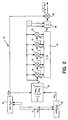
- Figure 3 is a block diagram of an apparatus for generating an envelope predistorted radio frequency signal in accordance with a second preferred embodiment of the present invention.
-
- Figure 1 depicts an apparatus for generating an envelope predistorted radio frequency signal in accordance with a first preferred embodiment of the present invention. A signal source 10 provides a complex baseband signal, including an in-phase component I and a quadrature component Q that are normalized and sampled at, for example, 10.5 kilosamples per second (KSPS). From source 10, the samples are applied to filter circuit 12, which might include a pair of raised cosine filters for shaping differential eight-phase shift keying (D8PSK) modulation, one filter for the in-phase component and one for the quadrature component. Filter circuit 12 resamples the provided signals at a multiple of the sampling rate of source 10, shown in Figure 1 as a resampling rate of 52.5 KSPS. The samples of the in-phase component Ik and the quadrature component Qk are applied from filters 12 to a gain control amplifier pair 14 that receives a gain control or scaling signal, which might be a constant value, from an appropriate source such as system software. A multiplier pair could be used in place of the gain control amplifier pair. The output of gain control amplifier pair 14 is applied to a calculation circuit 16 which calculates the magnitude of the scaled complex baseband envelope sample by determining the square root of the sum of the squares of the scaled in-phase component sample and the scaled quadrature component sample.
- Figure 2 is a block diagram of one preferred embodiment of an apparatus for determining an approximation of the magnitude of each complex sample k of the baseband signal. In Figure 2 an in-phase component Ik and a quadrature component Qk of a normalized baseband signal, which have been sampled at an appropriate sampling rate such as 52.5 KSPS, are applied to a first detection circuit 18 which determines the maximum of these components by determining for each sample pair whether the Ik component or the Qk component is the larger. The Ik component and the Qk component samples are also applied to a second detection circuit 20 which determines the minimum of these components by determining for each sample pair whether the Ik component or the Qk component is the smaller. The detected maximum value ("maxk") and the detected minimum value ("mink") for each sample pair are applied to calculating circuit 22 which computes the value yk = ½ (mink/maxk)2.
- The yk output from calculating circuit 22 is applied as an input to each of five multiplier circuits 24, 26, 28, 30 and 32. The yk output is also applied to a second input of multiplier 24. As a consequence, multiplier 24 provides as an output the value yk 2. This yk 2 output from multiplier 24 is applied to the second input of multiplier 26 and to a negative input to summation circuit 34. The output of multiplier 26 is thus the value yk 3. This output is applied to the second input of multiplier 28 and to a positive input of summation circuit 34. Multiplier 28 accordingly provides the output yk 4 which is used as the second input to multiplier 30 and which is applied to a negative input to summation circuit 34. Multiplier 30 then provides the output yk 5 to the second input of multiplier 32 and to a positive input to summation circuit 34. Multiplier 32 provides the output y6 to a negative input to summation circuit 34.
- Summation circuit 34 divides the sum of its inputs by 2, thus providing as its output the value ½ (-yk 2 + yk 3 - yk 4 + yk 5 - yk 6). This signal is applied as an input to summation circuit 36, which also receives as inputs the yk signal from calculation circuit 22 and the constant 1. The output of summation circuit 36 is thus the value { 1 + yk + ½ (-yk 2 + yk 3 - yk 4 + yk 5 - yk 6)}. This is equal to the value {(1 + yk)/2 + ½ (1 + yk - yk 2 + yk 3 - yk 4 + yk 5 - yk 6)}. This signal is applied from summation circuit 36 to one input of multiplier 38, which receives the maxk signal from detection circuit 18 at its second input. Consequently, the output of multiplier 38 is
- Returning to Figure 1, the input to calculation circuit 16 is C × Ik and C × Qk, and so the output from the calculation circuit is C × (Ik 2 + Qk 2)½ = C × uk = xk. This xk output is applied as an input to calculation circuit 40 which determines a value xk 2/3 + xk 4/5 + xk 6/7 + ...which is an approximation of the value {(atanh (xk))/xk) - 1. Calculation circuit 40 might be a look-up table for this purpose, having values to 16 bits. The output of calculation circuit 40 is applied to one input of summation circuit 42 which receives the constant 1 at its second input. It is preferred that calculation circuit 40, when in the form of a look-up table, compute the value of the segment {(atanh (xk))/xk} -1, and that the constant 1 be added at summation circuit 42 in order to provide the desired accuracy while maintaining the look-up table of a moderate size.
- The output of summation circuit 42 is thus the distortion factor (atanh (xk))/xk = (atanh (Cuk))/Cuk = Dk. This distortion factor is applied to one input of multiplier pair 44, which also receive the uk samples of the in-phase component Ik and the quadrature component Qk from filter circuit 12. Each sample of the in-phase component Ik and the quadrature component Qk is thus modified by the distortion factor Dk, so that the output of multiplier pair 44 is ejk(atanh(Cuk))/C. These samples of the modified signal are then resampled at a high rate, such as 50 megasamples per second (MSPS) in resampling circuit 46, and the resulting samples are applied to multiplier pair 48. A signal generator 50 applies sine and cosine outputs to sampling circuit 52. Signal generator 50 operates at a frequency less than half the sampling rate of resampling circuit 46, depicted in Figure 1 as a frequency of 21.4 MHz. Sampling circuit 52 samples the sine and cosine outputs from signal generator 50 at the same sampling rate as used by sampling circuit 46, depicted in Figure 1 as 50 MSPS. The sampled sine and cosine signals from sampling circuit 52 are applied to multiplier pair 48 so that the multiplier pair provide as outputs the intermediate frequency signal Dk × Ik sin 21.4 MHz and Dk × Qk cos 21.4 MHz. These signals are applied to summation circuit 54 which adds them to provide the predistorted upconverted intermediate frequency signal on its output line 56.
- This predistorted intermediate frequency signal is applied to digital-to-analog converter 58, which samples at the same rate as sampling circuit 46, shown in Figure 1 as 50 MSPS. The output of digital-to-analog converter 58 is applied to band pass filter 60. Band pass filter 60 is centered at the frequency of signal generator 50, depicted in Figure 1 as 21.4 MHz, and, has a bandwidth sufficient to avoid distortion of the predistorted envelope, for example a bandwidth in the order of 30 kHz. From band pass filter 60 the signal is applied to radio frequency attenuator 62 which receives an input, such as a constant value from system software, to set its power level. The output of attenuator 62 is V(t) = ej(t) (atanh(Cuk))/C. This signal is then applied to power amplifier 64 which has a transfer function of b × tanh (C × V(t)), where b is a constant. The output from power amplifier 64 is b × Cu(t)ej(t). Preferably, the gain control or scaling signal applied to gain control amplifier pair 14 is equal to C.
- Figure 3 depicts an apparatus for generating an envelope predistorted radio frequency signal in accordance with a second preferred embodiment of the present invention in which the scaling factor is determined by an adaptive feedback loop based on the root mean square error of the signal from the output power amplifier. Signal source 10 provides a complex baseband signal that is normalized and sampled and applied to filter circuit 12. The samples of the in-phase component and the quadrature component are applied to calculation circuit 16, which can be the circuit of Figure 2. The output of calculation circuit 16 is thus (Ik 2 + Qk 2)1/2 = uk. The output from the apparatus of Figure 3 is provided by power amplifier 64, and radio frequency coupler 70 couples a portion of that output to linear envelope detector 72. The detected envelope is applied to analog-to-digital converter 74 which samples at the same rate as digital-to-analog converter 58, depicted in Figure 3 as 50MSPS.
- The sampled output from analog-to-digital converter 74 is normalized to the maximum amount by normalizing circuit 76. The output of calculation circuit 16 is applied to a positive input of summing circuit 78, while the output from normalizing circuit 76 is applied to a negative input of the summing circuit. The input to summing circuit 78 from calculation circuit 16 represents the envelope before distortion, while the input to summing circuit 78 from normalizing circuit 76 represents the envelope after distortion. The resulting signal is applied by circuit 78 to one input of multiplier 80 which receives a weighting factor of - λ at its second input. The output from multiplier 80 is applied to one input of multiplying circuit 82 which receives the output from normalizing circuit 76 at its second input. The output from multiplying circuit 82 is applied through low pass filter 84 to sampler 86 which applies a sample of that output at periodic intervals of, for example, one minute to integrator 88. The output of integrator 88 is a scaling factor W and is applied to one input of multiplying circuit 90 which receives the uk outputs from calculation circuit 16 at its second input. The output of multiplier circuit 90 is thus W × uk = xk. This output is applied to calculation circuit 40 which calculates the value {(atanh (xk))/xk} - 1, as in the embodiment of Figure 1.
- As in the embodiment of Figure 1, the output of calculation circuit 40 is applied to summing circuit 42 in which the constant 1 is added, so that summing circuit 42 applies to multiplier pair 44 the distortion factor (atanh (xk))/xk= (atanh (Wuk))/Wuk = Dk. The uk samples of the in-phase component Ik and the quadrature component Qk are also applied to multiplier pair 44. Each sample of the in-phase component Ik and the quadrature component Qk is thus modified by the respective distortion factor Dk, so that the output of multiplier pair 44 is ejk (atanh(Wuk))/W. These samples of the modified signal are resampled in resampling circuit 46 at a high sampling rate, shown in Figure 3 as a resampling rate at 50 MSPS.
- The resampled output from resampling circuit 46 is applied to multiplier pair 48. Signal generator 50' provides an intermediate frequency signal of a frequency less than half the sampling rate of resampling circuit 46, shown in Figure 3 as a frequency of 17 MHz. Sampling circuit 52 samples the sine and cosine outputs from signal generator 50' at the same sampling rate as resampling circuit 46, shown in Figure 3 as a sampling rate of 50 MSPS. These sampled sine and cosine signals are applied to multiplier pair 48 so that the multiplier pair provides as outputs the intermediate frequency signals Dk × Ik sin 17 MHz and Dk × Ik cos 17 MHz. These signals are added in summation circuit 54, and the resulting predistorted, upconverted intermediate frequency signal is applied on line 56 to digital-to-analog converter 58 which samples at the same 50 MSPS rate as resampling circuit 46.
- The output from digital-to-analog converter 58 is applied to band pass filter 60' which is centered at the 17 MHz frequency of signal source 50' and which has a bandwidth sufficient to avoid distortion of the predistorted envelope, for example a bandwidth of MHz. The output from bandpass filter 60' is upconverted to a radio frequency in upconverter 61 and passed through driver amplifier 63 and power amplifier 64 to antenna 66. If desired, a radio frequency attenuator could be utilized, rather than upconverter 61 and drive amplifier 63, as in the embodiment of Figure 1. Likewise, an upconverter and a driver amplifier could be used in the Figure 1 embodiment, if desired.
- The feedback circuit of Figure 3 results in the signal W that is applied from integrator 88 to multiplier 90 converging to the current value of C, the transfer function of output amplifier 64. It is possible to set the gain of the feedback loop so that it converges in just a few iterations. The value of the feedback gain λ which guarantees stable conversion is upper bounded by the mean square value of the feedback envelope after being normalized by circuit 76.
- Predistorting the digital envelope of the baseband signal before upconversion to the radio frequency, followed by digital-to-analog conversion, in accordance with the present invention avoids impressing of analog pickup noise directly on the transmitted envelope, as would occur if the envelope correction were performed on the radio frequency analog signal. Implementation of the present invention does not require significant hardware. It can be accomplished in software or firmware. Implementation on a gate array, such as a field programmable gate array, is convenient.
- Although the present invention has been described with reference to preferred embodiments, various alterations, rearrangements, and substitutions could be made, and still the result would be within the scope of the invention.
Claims (13)
- A method of predistorting a complex baseband signal having an in-phase component I and a quadrature component Q, said method comprising the steps ofsampling the complex baseband signal to obtain k complex samples of the in-phase component Ik and of the quadrature component Qk;for each of the k samples determining a respective distortion factor Dk;multiplying each sample of the in-phase component Ik and of the quadrature component Qk by its respective distortion factor Dk to obtain a predistorted in-phase component sample and a predistorted quadrature component sample;up-converting each of the predistorted in-phase component samples and each of the predistorted quadrature component samples to provide a sampled radio frequency in-phase signal and a sampled radio frequency quadrature signal; andcombining the sampled radio frequency in-phase signal and the sampled radio frequency quadrature signal to provide a predistorted carrier signal.
- A method as claimed in claim 1, wherein for each of the k complex samples the respective distortion factor Dk is determined as Dk = (atanh (Cuk))/ Cuk, where uk is the magnitude of the complex sample k of the baseband signal, and C is a constant.
- A method as claimed in claim 1, wherein for each of the k samples the respective distortion factor Dk is determined by:determining the magnitude Ik of each of the k samples of the in-phase component and the magnitude Qk of each of the k samples of the quadrature component;for each of the k pairs of corresponding samples of the in-phase component and of the quadrature component, determining a respective value of xk = C × (Ik 2 + Qk 2)½; andfor each value of xk, determining a value of the respective distortion factor Dk = (atanh (xk))/ xk.
- A method of generating an envelope predistorted radio frequency signal, said method comprising the steps ofproviding an envelope modulated signal including a complex baseband signal having an in-phase component I and a quadrature component Q;sampling the complex baseband signal to obtain k complex samples of the in-phase component Ik and of the quadrature component Qk;for each of the k samples determining a respective distortion factor Dk;multiplying each sample of the in-phase component Ik and of the quadrature component Qk by its respective distortion factor Dk to obtain a predistorted in-phase component sample and a predistorted quadrature component sample;up-converting each of the predistorted in-phase component samples and each of the predistorted quadrature component samples to provide a sampled intermediate frequency in-phase signal and a sampled intermediate frequency quadrature signal;combining the sampled intermediate frequency in-phase signal and the sampled intermediate frequency quadrature signal to provide a predistorted intermediate frequency signal; andconverting the predistorted intermediate frequency signal to an analog signal.
- A method as claimed in claim 4, wherein for each of the k samples the respective distortion factor Dk is determined as Dk = (atanh (Cuk))/ Cuk, where uk is the magnitude of the complex sample k of the baseband signal, and C is a constant.
- A method as claimed in claim 4, wherein for each of the k samples the respective distortion factor Dk is determined by:determining the magnitude Ik of each of the k samples of the in-phase component and the magnitude Qk of each of the k samples of the quadrature component;for each of the k pairs of corresponding samples of the in-phase component and of the quadrature component, determining a respective value of xk = C × (Ik 2 + Qk 2)½; andfor each value of xk, determining a value of the respective distortion factor Dk = (atanh (xk))/ xk.
- Apparatus for predistorting a complex baseband signal having an in-phase component I and a quadrature component Q, said apparatus comprising:a sampling circuit for providing k complex samples of the in-phase component Ik and the quadrature component Qk;a distortion determining circuit for determining for each of the k samples a respective distortion factor Dk;a first multiplier for multiplying each sample of the in-phase component Ik and of the quadrature component Qk by its respective distortion factor Dk to obtain a predistorted in-phase component sample and a predistorted quadrature component sample;a second multiplier for up-converting each of the predistorted in-phase component samples and each of the predistorted quadrature component samples to provide a sampled radio frequency in-phase signal and a sampled radio frequency quadrature signal; anda summing circuit for combining the sampled radio frequency in-phase signal and the sampled radio frequency quadrature signal to provide a predistorted carrier signal.
- Apparatus as claimed in claim 7, wherein said distortion determining circuit comprises a calculation circuit for determining for each of the k complex samples the respective distortion factor Dk = (atanh (Cuk))/ Cuk, where uk is the magnitude of the complex sample k of the baseband signal, and C is a constant.
- Apparatus as claimed in claim 7 , wherein said distortion determining circuit comprises:a first calculation circuit for determining for each of the k pairs of corresponding samples of the in-phase component and of the quadrature component, a respective value of xk = C × (Ik 2 + Qk 2)½; anda second calculation circuit for determining for each value of xk a value of the respective distortion factor Dk.
- Apparatus as claimed in claim 9 , wherein said first calculation circuit comprises:first means for detecting the maximum value of Ik and Qk by determining the larger of Ik and Qk;second means for detecting the minimum value of Ik and Qk by determining the smaller of Ik and Qk;third means for calculating a value of yk = ½ {(the detected minimum value) □ (the detected maximum value)}2; andfourth means for calculating a value if (Ik 2 + Qk 2)1/2 as a function of yk .
- Apparatus for generating an envelope predistorted radio frequency signal, said apparatus comprising:a source of an envelope modulated signal including a complex baseband signal having an in-phase component I and a quadrature component Q;a sampling circuit for providing k complex samples of the in-phase component Ik and the quadrature component Qk;a distortion determining circuit for determining for each of the k samples a respective distortion factor Dk;a first multiplier for multiplying each sample of the in-phase component Ik and of the quadrature component Qk by its respective distortion factor Dk to obtain a predistorted in-phase component sample and a predistorted quadrature component sample;a second multiplier for up-converting each of the predistorted in-phase component samples and each of the predistorted quadrature component samples to provide a sampled intermediate frequency in-phase signal and a sampled intermediate frequency quadrature signal;a summing circuit for combining the sampled intermediate frequency in-phase signal and the sampled intermediate frequency quadrature signal to provide a predistorted intermediate frequency signal; anda digital-to-analog converter for converting the predistorted intermediate frequency signal to an analog signal.
- Apparatus as claimed in claim 11, wherein said distortion determining circuit comprises:a first calculation circuit for determining for each of the k pairs of corresponding samples of the in-phase component and of the quadrature component, a respective value of xk = W × (Ik 2 + Qk 2)½; anda second calculation circuit for determining for each value of xk a value of the respective distortion factor Dk.
- Apparatus as claimed in claim 12, wherein said first calculation circuit comprises:first means for detecting the maximum value of Ik and Qk by determining the larger of Ik and Qk;second means for detecting the minimum value of Ik and Qk by determining the smaller of Ik and Qk;third means for calculating a value of yk = ½ {(the detected minimum value) □ (the detected maximum value)}2; andfourth means for calculating a value if (Ik2 + Qk2)1/2 as a function of yk.
Applications Claiming Priority (2)
| Application Number | Priority Date | Filing Date | Title |
|---|---|---|---|
| US624149 | 1996-04-08 | ||
| US09/624,149 US6751268B1 (en) | 2000-07-24 | 2000-07-24 | Bandpass predistorting expansion method and apparatus for digital radio transmission |
Publications (3)
| Publication Number | Publication Date |
|---|---|
| EP1176777A2 true EP1176777A2 (en) | 2002-01-30 |
| EP1176777A3 EP1176777A3 (en) | 2005-08-24 |
| EP1176777B1 EP1176777B1 (en) | 2007-10-24 |
Family
ID=24500838
Family Applications (1)
| Application Number | Title | Priority Date | Filing Date |
|---|---|---|---|
| EP01116632A Expired - Lifetime EP1176777B1 (en) | 2000-07-24 | 2001-07-12 | Predistortion of quadrature signals |
Country Status (4)
| Country | Link |
|---|---|
| US (1) | US6751268B1 (en) |
| EP (1) | EP1176777B1 (en) |
| JP (1) | JP3655851B2 (en) |
| DE (1) | DE60131049T2 (en) |
Cited By (2)
| Publication number | Priority date | Publication date | Assignee | Title |
|---|---|---|---|---|
| US6778614B1 (en) * | 2000-10-17 | 2004-08-17 | Northrop Grumman Corporation | Complex baseband envelope computation |
| EP1251667A3 (en) * | 2001-04-16 | 2009-02-11 | Northrop Grumman Corporation | Predistortion for use with amplifiers which have hyperbolic tangent distortion |
Families Citing this family (5)
| Publication number | Priority date | Publication date | Assignee | Title |
|---|---|---|---|---|
| DE60024890T2 (en) * | 2000-09-13 | 2006-06-14 | Nortel Networks Ltd | MULTI-USER DETECTION IN A CDMA COMMUNICATION SYSTEM |
| KR100374828B1 (en) * | 2000-09-15 | 2003-03-04 | 엘지전자 주식회사 | Adaptive predistortion transmitter |
| US6819938B2 (en) * | 2001-06-26 | 2004-11-16 | Qualcomm Incorporated | System and method for power control calibration and a wireless communication device |
| US7349365B2 (en) * | 2002-10-22 | 2008-03-25 | Mitsubishi Electric Research Laboratories, Inc. | Mobile telephone messaging by baseband envelope modulation |
| US10320461B2 (en) * | 2014-07-08 | 2019-06-11 | New York University | System, method and computer-readable medium for estimating direction of arrival of a signal incident on at least one antenna array |
Citations (2)
| Publication number | Priority date | Publication date | Assignee | Title |
|---|---|---|---|---|
| EP0533363A2 (en) * | 1991-09-03 | 1993-03-24 | AT&T Corp. | Non-linear encoder and decoder for information transmission through non-linear channels |
| US5867065A (en) * | 1997-05-07 | 1999-02-02 | Glenayre Electronics, Inc. | Frequency selective predistortion in a linear transmitter |
-
2000
- 2000-07-24 US US09/624,149 patent/US6751268B1/en not_active Expired - Lifetime
-
2001
- 2001-07-12 DE DE60131049T patent/DE60131049T2/en not_active Expired - Lifetime
- 2001-07-12 EP EP01116632A patent/EP1176777B1/en not_active Expired - Lifetime
- 2001-07-24 JP JP2001223204A patent/JP3655851B2/en not_active Expired - Lifetime
Patent Citations (2)
| Publication number | Priority date | Publication date | Assignee | Title |
|---|---|---|---|---|
| EP0533363A2 (en) * | 1991-09-03 | 1993-03-24 | AT&T Corp. | Non-linear encoder and decoder for information transmission through non-linear channels |
| US5867065A (en) * | 1997-05-07 | 1999-02-02 | Glenayre Electronics, Inc. | Frequency selective predistortion in a linear transmitter |
Cited By (2)
| Publication number | Priority date | Publication date | Assignee | Title |
|---|---|---|---|---|
| US6778614B1 (en) * | 2000-10-17 | 2004-08-17 | Northrop Grumman Corporation | Complex baseband envelope computation |
| EP1251667A3 (en) * | 2001-04-16 | 2009-02-11 | Northrop Grumman Corporation | Predistortion for use with amplifiers which have hyperbolic tangent distortion |
Also Published As
| Publication number | Publication date |
|---|---|
| DE60131049T2 (en) | 2008-02-07 |
| EP1176777A3 (en) | 2005-08-24 |
| JP2002135341A (en) | 2002-05-10 |
| DE60131049D1 (en) | 2007-12-06 |
| EP1176777B1 (en) | 2007-10-24 |
| US6751268B1 (en) | 2004-06-15 |
| JP3655851B2 (en) | 2005-06-02 |
Similar Documents
| Publication | Publication Date | Title |
|---|---|---|
| US6928122B2 (en) | Amplifier predistortion system and method | |
| US6587513B1 (en) | Predistorter | |
| EP1085668B1 (en) | A method and apparatus for reducing adjacent channel power in wireless communication systems | |
| KR101107866B1 (en) | An uncorrelated adaptive predistorter | |
| US8026762B2 (en) | High efficiency transmitter for wireless communication | |
| US6993091B2 (en) | Correction of DC-offset of I/Q modulator | |
| US20020065048A1 (en) | Method and apparatus for compensating for distortion in radio apparatus | |
| JPH06505604A (en) | Adaptive phase control of power amplifier predistorter | |
| KR20030025620A (en) | Predistortion type digital linearier with digital if circuit | |
| JPH09512692A (en) | Apparatus and method for providing a baseband digital error signal in an adaptive precompensator | |
| US20030118126A1 (en) | Apparatus and method for compensating error for analog quadrature modulator (AQM) | |
| US6654426B2 (en) | Correction of nonlinearity of I/Q modulator | |
| EP1251667B1 (en) | Predistortion for use with amplifiers which have hyperbolic tangent distortion | |
| US6104239A (en) | Method for correcting frequency-varying nonlinear errors and digital correction circuit implementing same | |
| US6751268B1 (en) | Bandpass predistorting expansion method and apparatus for digital radio transmission | |
| JP2004165900A (en) | Communication device | |
| JPH0531326B2 (en) | ||
| JP2006135612A (en) | Transmission apparatus and distortion compensating method | |
| KR19990043668A (en) | Apparatus and method for linearizing power amplifier of wireless communication system by adaptive predistortion method | |
| JP3436250B2 (en) | Transmission device | |
| KR100445326B1 (en) | Linear Power Amplifier using the Digital Signal Processor | |
| US20040169557A1 (en) | Signal processing apparatus | |
| KR19990060378A (en) | Linearization device and method of power amplifier | |
| RU2172552C1 (en) | Device and method for linearizing power amplifier in mobile radio communication system | |
| US20020173285A1 (en) | Pre-amplification software linearizer |
Legal Events
| Date | Code | Title | Description |
|---|---|---|---|
| PUAI | Public reference made under article 153(3) epc to a published international application that has entered the european phase |
Free format text: ORIGINAL CODE: 0009012 |
|
| AK | Designated contracting states |
Kind code of ref document: A2 Designated state(s): AT BE CH CY DE DK ES FI FR GB GR IE IT LI LU MC NL PT SE TR |
|
| AX | Request for extension of the european patent |
Free format text: AL;LT;LV;MK;RO;SI |
|
| RAP1 | Party data changed (applicant data changed or rights of an application transferred) |
Owner name: NORTHROP GRUMMAN CORPORATION |
|
| RAP1 | Party data changed (applicant data changed or rights of an application transferred) |
Owner name: NORTHROP GRUMMAN CORPORATION |
|
| PUAL | Search report despatched |
Free format text: ORIGINAL CODE: 0009013 |
|
| RIC1 | Information provided on ipc code assigned before grant |
Ipc: 7H 03F 1/32 B Ipc: 7H 04L 27/36 A |
|
| AK | Designated contracting states |
Kind code of ref document: A3 Designated state(s): AT BE CH CY DE DK ES FI FR GB GR IE IT LI LU MC NL PT SE TR |
|
| AX | Request for extension of the european patent |
Extension state: AL LT LV MK RO SI |
|
| 17P | Request for examination filed |
Effective date: 20050902 |
|
| AKX | Designation fees paid |
Designated state(s): DE FR GB |
|
| 17Q | First examination report despatched |
Effective date: 20060214 |
|
| GRAP | Despatch of communication of intention to grant a patent |
Free format text: ORIGINAL CODE: EPIDOSNIGR1 |
|
| GRAS | Grant fee paid |
Free format text: ORIGINAL CODE: EPIDOSNIGR3 |
|
| GRAA | (expected) grant |
Free format text: ORIGINAL CODE: 0009210 |
|
| AK | Designated contracting states |
Kind code of ref document: B1 Designated state(s): DE FR GB |
|
| REG | Reference to a national code |
Ref country code: GB Ref legal event code: FG4D |
|
| REF | Corresponds to: |
Ref document number: 60131049 Country of ref document: DE Date of ref document: 20071206 Kind code of ref document: P |
|
| ET | Fr: translation filed | ||
| PLBE | No opposition filed within time limit |
Free format text: ORIGINAL CODE: 0009261 |
|
| STAA | Information on the status of an ep patent application or granted ep patent |
Free format text: STATUS: NO OPPOSITION FILED WITHIN TIME LIMIT |
|
| 26N | No opposition filed |
Effective date: 20080725 |
|
| REG | Reference to a national code |
Ref country code: GB Ref legal event code: 732E Free format text: REGISTERED BETWEEN 20110505 AND 20110511 |
|
| REG | Reference to a national code |
Ref country code: GB Ref legal event code: 732E Free format text: REGISTERED BETWEEN 20110512 AND 20110518 |
|
| REG | Reference to a national code |
Ref country code: FR Ref legal event code: TP Owner name: NORTHROP GRUMMAN SYSTEMS CORPORATION, US Effective date: 20120103 |
|
| REG | Reference to a national code |
Ref country code: DE Ref legal event code: R082 Ref document number: 60131049 Country of ref document: DE Representative=s name: WUESTHOFF & WUESTHOFF PATENT- UND RECHTSANWAEL, DE |
|
| REG | Reference to a national code |
Ref country code: DE Ref legal event code: R082 Ref document number: 60131049 Country of ref document: DE Representative=s name: WUESTHOFF & WUESTHOFF PATENT- UND RECHTSANWAEL, DE Effective date: 20120814 Ref country code: DE Ref legal event code: R081 Ref document number: 60131049 Country of ref document: DE Owner name: NORTHROP GRUMMAN SYSTEMS CORPORATION, US Free format text: FORMER OWNER: NORTHROP GRUMMAN CORP., LOS ANGELES, US Effective date: 20120814 Ref country code: DE Ref legal event code: R081 Ref document number: 60131049 Country of ref document: DE Owner name: NORTHROP GRUMMAN SYSTEMS CORPORATION, LOS ANGE, US Free format text: FORMER OWNER: NORTHROP GRUMMAN CORP., LOS ANGELES, CALIF., US Effective date: 20120814 Ref country code: DE Ref legal event code: R082 Ref document number: 60131049 Country of ref document: DE Representative=s name: WUESTHOFF & WUESTHOFF, PATENTANWAELTE PARTG MB, DE Effective date: 20120814 |
|
| PGFP | Annual fee paid to national office [announced via postgrant information from national office to epo] |
Ref country code: DE Payment date: 20130722 Year of fee payment: 13 |
|
| PGFP | Annual fee paid to national office [announced via postgrant information from national office to epo] |
Ref country code: FR Payment date: 20130722 Year of fee payment: 13 Ref country code: GB Payment date: 20130719 Year of fee payment: 13 |
|
| REG | Reference to a national code |
Ref country code: DE Ref legal event code: R119 Ref document number: 60131049 Country of ref document: DE |
|
| GBPC | Gb: european patent ceased through non-payment of renewal fee |
Effective date: 20140712 |
|
| REG | Reference to a national code |
Ref country code: FR Ref legal event code: ST Effective date: 20150331 |
|
| PG25 | Lapsed in a contracting state [announced via postgrant information from national office to epo] |
Ref country code: DE Free format text: LAPSE BECAUSE OF NON-PAYMENT OF DUE FEES Effective date: 20150203 |
|
| REG | Reference to a national code |
Ref country code: DE Ref legal event code: R119 Ref document number: 60131049 Country of ref document: DE Effective date: 20150203 |
|
| PG25 | Lapsed in a contracting state [announced via postgrant information from national office to epo] |
Ref country code: FR Free format text: LAPSE BECAUSE OF NON-PAYMENT OF DUE FEES Effective date: 20140731 Ref country code: GB Free format text: LAPSE BECAUSE OF NON-PAYMENT OF DUE FEES Effective date: 20140712 |