EP1178331A2 - Object detection by signal field mapping - Google Patents
Object detection by signal field mapping Download PDFInfo
- Publication number
- EP1178331A2 EP1178331A2 EP01306307A EP01306307A EP1178331A2 EP 1178331 A2 EP1178331 A2 EP 1178331A2 EP 01306307 A EP01306307 A EP 01306307A EP 01306307 A EP01306307 A EP 01306307A EP 1178331 A2 EP1178331 A2 EP 1178331A2
- Authority
- EP
- European Patent Office
- Prior art keywords
- signal
- recited
- emitter
- defined field
- controller
- Prior art date
- Legal status (The legal status is an assumption and is not a legal conclusion. Google has not performed a legal analysis and makes no representation as to the accuracy of the status listed.)
- Withdrawn
Links
Images
Classifications
-
- G—PHYSICS
- G01—MEASURING; TESTING
- G01S—RADIO DIRECTION-FINDING; RADIO NAVIGATION; DETERMINING DISTANCE OR VELOCITY BY USE OF RADIO WAVES; LOCATING OR PRESENCE-DETECTING BY USE OF THE REFLECTION OR RERADIATION OF RADIO WAVES; ANALOGOUS ARRANGEMENTS USING OTHER WAVES
- G01S15/00—Systems using the reflection or reradiation of acoustic waves, e.g. sonar systems
- G01S15/02—Systems using the reflection or reradiation of acoustic waves, e.g. sonar systems using reflection of acoustic waves
- G01S15/04—Systems determining presence of a target
-
- E—FIXED CONSTRUCTIONS
- E05—LOCKS; KEYS; WINDOW OR DOOR FITTINGS; SAFES
- E05F—DEVICES FOR MOVING WINGS INTO OPEN OR CLOSED POSITION; CHECKS FOR WINGS; WING FITTINGS NOT OTHERWISE PROVIDED FOR, CONCERNED WITH THE FUNCTIONING OF THE WING
- E05F15/00—Power-operated mechanisms for wings
- E05F15/40—Safety devices, e.g. detection of obstructions or end positions
- E05F15/42—Detection using safety edges
- E05F15/43—Detection using safety edges responsive to disruption of energy beams, e.g. light or sound
- E05F15/431—Detection using safety edges responsive to disruption of energy beams, e.g. light or sound specially adapted for vehicle windows or roofs
-
- G—PHYSICS
- G01—MEASURING; TESTING
- G01S—RADIO DIRECTION-FINDING; RADIO NAVIGATION; DETERMINING DISTANCE OR VELOCITY BY USE OF RADIO WAVES; LOCATING OR PRESENCE-DETECTING BY USE OF THE REFLECTION OR RERADIATION OF RADIO WAVES; ANALOGOUS ARRANGEMENTS USING OTHER WAVES
- G01S13/00—Systems using the reflection or reradiation of radio waves, e.g. radar systems; Analogous systems using reflection or reradiation of waves whose nature or wavelength is irrelevant or unspecified
- G01S13/02—Systems using reflection of radio waves, e.g. primary radar systems; Analogous systems
- G01S13/04—Systems determining presence of a target
-
- E—FIXED CONSTRUCTIONS
- E05—LOCKS; KEYS; WINDOW OR DOOR FITTINGS; SAFES
- E05F—DEVICES FOR MOVING WINGS INTO OPEN OR CLOSED POSITION; CHECKS FOR WINGS; WING FITTINGS NOT OTHERWISE PROVIDED FOR, CONCERNED WITH THE FUNCTIONING OF THE WING
- E05F15/00—Power-operated mechanisms for wings
- E05F15/40—Safety devices, e.g. detection of obstructions or end positions
- E05F15/42—Detection using safety edges
- E05F15/43—Detection using safety edges responsive to disruption of energy beams, e.g. light or sound
- E05F2015/432—Detection using safety edges responsive to disruption of energy beams, e.g. light or sound with acoustical sensors
- E05F2015/433—Detection using safety edges responsive to disruption of energy beams, e.g. light or sound with acoustical sensors using reflection from the obstruction
-
- E—FIXED CONSTRUCTIONS
- E05—LOCKS; KEYS; WINDOW OR DOOR FITTINGS; SAFES
- E05Y—INDEXING SCHEME RELATING TO HINGES OR OTHER SUSPENSION DEVICES FOR DOORS, WINDOWS OR WINGS AND DEVICES FOR MOVING WINGS INTO OPEN OR CLOSED POSITION, CHECKS FOR WINGS AND WING FITTINGS NOT OTHERWISE PROVIDED FOR, CONCERNED WITH THE FUNCTIONING OF THE WING
- E05Y2900/00—Application of doors, windows, wings or fittings thereof
- E05Y2900/50—Application of doors, windows, wings or fittings thereof for vehicles
- E05Y2900/53—Application of doors, windows, wings or fittings thereof for vehicles characterised by the type of wing
- E05Y2900/55—Windows
Definitions
- the present invention relates to object detection, and more particularly to an apparatus for detecting an object in the path of a vehicle power window.
- Power window mechanisms are commonly known. Recently, one-touch up power windows have been included in vehicles which allow the window to be closed by a single press of the power window operating button. Additionally, such mechanisms are known for vehicle sunroofs and the like. The proliferation of such power window mechanisms has increased the possibility that an object could be captured in the closing window.
- the object detection system of the present invention generally includes an emitter, a receiver, and a controller attachable to a window assembly that typically includes a moveable closure member and a frame. Although a window is shown and described, the present invention is similarly applicable to a vehicle sunroof/moonroof or other closure members.
- the emitter transmits a signal through a defined field adjacent a closure path of a moveable closure member.
- the controller preferably constructs a "normal" map signature of the received signal which includes the obstructions normally within the defined field.
- the "normal" map signature is used by the controller as a reference and indicates that no unknown objects are within the defined field.
- a variation from the "normal" map signature is constructed by the controller.
- the controller compares the varied map signature to the "normal” map signature and identifies the differences. Any difference from the "normal” map signature is identified as an unknown object in the closure path and is an undesirable obstruction.
- the controller halts or reverses the movement of the moveable glass member to prevent trapping the object between the closing moveable glass member and the frame.
- the emitter is maintained in a dormant state and operated only when the moveable glass member is being closed.
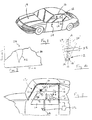
- FIG. 1 illustrates an object detection system 10 according to the present invention.
- the system 10 is preferably attachable or integral to a window assembly 12 having a moveable closure member 14.
- the moveable closure member 14, such as a vehicle window is movable through a closure path (shown schematically by double arrow 15) within a frame 16 typical of a vehicle 17 having a power window, sunroof, or the like.
- the system 10 generally includes an emitter 18, a receiver 20, and a controller 22 attachable to the window assembly 12.
- the emitter 18 transmits a signal (shown schematically at 24) through a defined field 26 adjacent the closure path 15 of moveable closure member 14.
- the controller 22 constructs a map of the signal 24 received by the receiver 20 such that insertion of an object (shown schematically at 33) within the defined field produces a variation in the map.
- the controller 22 can then halt or reverse the movement of the moveable closure member 14 to prevent trapping object 33 between the closing moveable glass member 14 and the frame 16.
- the emitter 18 is preferably positioned adjacent the moveable glass member 14 in the frame 16.
- the receiver 20 is mounted adjacent the moveable glass member 14 in the frame 16 to receive the signal 24 reflection. It is further preferred that a second emitter 18' and receiver 20' are mounted adjacent the moveable closure member 14.
- the second emitter 18' transmits a second signal (shown schematically at 24') through a second defined field 26' adjacent the closure path 15 of moveable closure member 14.
- controller 22 halts or reverses the movement of the moveable glass member 14 to prevent trapping the object between the closing moveable closure member 14 and the frame 16.
- controller 22 communicates with an actuator 34 for the moveab le closure member 14.
- the emitter 18 can be maintained in a dormant state and operated only when the actuator 34 is operating and the moveable closure member 14 is being closed.
- the emitter 18 transmits the signal 24 within the defined field 26.
- the signal 24 is preferably an electromagnetic or ultrasonic signal and emitter 18 may transmit the signal 24 continuously or in a pulse to minimize power usage.
- the transmitted signal 24 will reflect from obstructions that are always within the defined field 26 such as portions of the frame 16.
- the receiver 20 will therefore receive a relatively constant reflection which is identified by the controller 22.
- the controller 22 constructs a map 28 of the received signal 24 as illustrated in Figure 3. Mapping algorithms can be provided by signal processing circuitry well known in the art of processing signals and further description of these algorithms will not be discussed. Although operation of only the first emitter 18 and receiver 20 will be described it should be realized that such operation is applicable to the second emitter 18' and receiver 20' and to any number of emitter and receiver combinations.
- the "normal" map signature 30 of the received signal 24 including the obstructions normally within the defined field 26 ( Figure 2) is used by the controller 22 as a reference.
- the "normal” map signature 30 indicates to the controller 22 that no unknown objects are within the defined field 26.
- the controller 22 compares the reflected signal 24 to the "normal" map signature 30, see Figure 3. If the reflected signal 24 is within a predetermined range of the "normal” map signature 30, then a determination is made that no unknown objects are within the defined field 26. However, when an unknown object 33 ( Figure 2) enters within the defined field 26, a variation from the "normal" map signature 30 such as varied map signature 32 will be constructed by the controller 22. The controller 22 compares the varied map signature 32 to the "normal” map signature 30 and identifies any differences between the "normal” map signature 30 and the varied map signature 32. The controller 22 thus determines that an unknown object 33 is within the defined field 26 and can stop movement of the moveable closure member 14 as described above.
- Controller 22 is programmed to recognize movement of the moveable closure member 14 through the closure path 15. As the moveable glass member 14 moves through the defined field 26 the "normal" map signature 30 can be accordingly adjusted to prevent a false object detection caused by movement of the moveable closure member 14.
- the defined fields 26, 26' can be set to scan both inside and outside the plane of the moveable closure member 14.
- the moveable closure member 14 does not move through the defined fields 26, 26' and the "normal" map signature 30 is not adjusted.
- Any object 33 that is identified in both defined fields 26, 26' both inside and outside the window, is in the closure path 15 and is an undesirable obstruction.
- the controller 22 can halt or reverse the movement of the moveable glass member 14.
Abstract
Description
- The present invention relates to object detection, and more particularly to an apparatus for detecting an object in the path of a vehicle power window.
- Power window mechanisms are commonly known. Recently, one-touch up power windows have been included in vehicles which allow the window to be closed by a single press of the power window operating button. Additionally, such mechanisms are known for vehicle sunroofs and the like. The proliferation of such power window mechanisms has increased the possibility that an object could be captured in the closing window.
- Accordingly, it is desirable to provide an object detection system to prevent such possibility of capture. It is further desirable to provide a robust, reliable, lightweight and inexpensive system for vehicle use.
- The object detection system of the present invention generally includes an emitter, a receiver, and a controller attachable to a window assembly that typically includes a moveable closure member and a frame. Although a window is shown and described, the present invention is similarly applicable to a vehicle sunroof/moonroof or other closure members.
- In operation the emitter transmits a signal through a defined field adjacent a closure path of a moveable closure member. The controller preferably constructs a "normal" map signature of the received signal which includes the obstructions normally within the defined field. The "normal" map signature is used by the controller as a reference and indicates that no unknown objects are within the defined field.
- However, when an unknown object enters within the defined field, a variation from the "normal" map signature is constructed by the controller. The controller compares the varied map signature to the "normal" map signature and identifies the differences. Any difference from the "normal" map signature is identified as an unknown object in the closure path and is an undesirable obstruction.
- When an object is determined to be in the defined field, the controller halts or reverses the movement of the moveable glass member to prevent trapping the object between the closing moveable glass member and the frame. Preferably, the emitter is maintained in a dormant state and operated only when the moveable glass member is being closed.
- The various features and advantages of this invention will become apparent to those skilled in the art from the following detailed description of the currently preferred embodiment. The drawings that accompany the detailed description can be briefly described as follows:
- Figure 1 is a general schematic representation of a vehicle having a moveable window;
- Figure 2 is a general schematic representation of the object detection system according to the present invention;
- Figure 3 is a graphical representation of a mapped signal according to the present invention; and
- Figure 4 is a top-down view of the moveable closure member line illustrating an alternate embodiment of the object detection system according to the present invention.
-
- Figure 1 illustrates an
object detection system 10 according to the present invention. Thesystem 10 is preferably attachable or integral to awindow assembly 12 having amoveable closure member 14. Themoveable closure member 14, such as a vehicle window is movable through a closure path (shown schematically by double arrow 15) within aframe 16 typical of avehicle 17 having a power window, sunroof, or the like. - As shown in Figure 2, the
system 10 generally includes anemitter 18, areceiver 20, and a controller 22 attachable to thewindow assembly 12. As will be more fully described below, theemitter 18 transmits a signal (shown schematically at 24) through adefined field 26 adjacent the closure path 15 ofmoveable closure member 14. The controller 22 constructs a map of the signal 24 received by thereceiver 20 such that insertion of an object (shown schematically at 33) within the defined field produces a variation in the map. The controller 22 can then halt or reverse the movement of themoveable closure member 14 to prevent trapping object 33 between the closingmoveable glass member 14 and theframe 16. - The
emitter 18 is preferably positioned adjacent themoveable glass member 14 in theframe 16. Thereceiver 20 is mounted adjacent themoveable glass member 14 in theframe 16 to receive the signal 24 reflection. It is further preferred that a second emitter 18' and receiver 20' are mounted adjacent themoveable closure member 14. The second emitter 18' transmits a second signal (shown schematically at 24') through a second defined field 26' adjacent the closure path 15 ofmoveable closure member 14. - When an unknown object 33 is determined to be within the
defined field 26, the controller 22 halts or reverses the movement of themoveable glass member 14 to prevent trapping the object between the closingmoveable closure member 14 and theframe 16. To achieve this control, controller 22 communicates with anactuator 34 for the moveable closure member 14. To conserve power, theemitter 18 can be maintained in a dormant state and operated only when theactuator 34 is operating and themoveable closure member 14 is being closed. - In operation, the
emitter 18 transmits the signal 24 within thedefined field 26. The signal 24 is preferably an electromagnetic or ultrasonic signal andemitter 18 may transmit the signal 24 continuously or in a pulse to minimize power usage. - The transmitted signal 24 will reflect from obstructions that are always within the
defined field 26 such as portions of theframe 16. Thereceiver 20 will therefore receive a relatively constant reflection which is identified by the controller 22. Whereas thereceiver 20 receives a relatively constant signal 24 reflection, the controller 22 constructs amap 28 of the received signal 24 as illustrated in Figure 3. Mapping algorithms can be provided by signal processing circuitry well known in the art of processing signals and further description of these algorithms will not be discussed. Although operation of only thefirst emitter 18 andreceiver 20 will be described it should be realized that such operation is applicable to the second emitter 18' and receiver 20' and to any number of emitter and receiver combinations. - The "normal"
map signature 30 of the received signal 24 including the obstructions normally within the defined field 26 (Figure 2) is used by the controller 22 as a reference. The "normal"map signature 30 indicates to the controller 22 that no unknown objects are within thedefined field 26. - To identify whether an object 33 is within the
defined field 26, the controller 22 compares the reflected signal 24 to the "normal"map signature 30, see Figure 3. If the reflected signal 24 is within a predetermined range of the "normal"map signature 30, then a determination is made that no unknown objects are within thedefined field 26. However, when an unknown object 33 (Figure 2) enters within thedefined field 26, a variation from the "normal"map signature 30 such asvaried map signature 32 will be constructed by the controller 22. The controller 22 compares thevaried map signature 32 to the "normal"map signature 30 and identifies any differences between the "normal"map signature 30 and thevaried map signature 32. The controller 22 thus determines that an unknown object 33 is within thedefined field 26 and can stop movement of themoveable closure member 14 as described above. - Controller 22 is programmed to recognize movement of the
moveable closure member 14 through the closure path 15. As themoveable glass member 14 moves through thedefined field 26 the "normal"map signature 30 can be accordingly adjusted to prevent a false object detection caused by movement of themoveable closure member 14. - In an alternate embodiment of Figure 4, the
defined fields 26, 26' can be set to scan both inside and outside the plane of themoveable closure member 14. Themoveable closure member 14 does not move through thedefined fields 26, 26' and the "normal"map signature 30 is not adjusted. Any object 33 that is identified in bothdefined fields 26, 26' both inside and outside the window, is in the closure path 15 and is an undesirable obstruction. Thus, as illustrated in the top view of Figure 4, if the object 33 is in bothdefined fields 26, 26', the controller 22 can halt or reverse the movement of themoveable glass member 14. - The foregoing description is exemplary rather than defined by the limitations within. Many modifications and variations of the present invention are possible in light of the above teachings. The preferred embodiments of this invention have been disclosed, however, one of ordinary skill in the art would recognize that certain modifications would come within the scope of this invention. It is, therefore, to be understood that within the scope of the appended claims, the invention may be practiced otherwise than as specifically described. For that reason the following claims should be studied to determine the true scope and content of this invention.
Claims (17)
- An object detection system (10) for a vehicle comprising:an emitter (18) mounted to transmit a signal (24) within a defined field (26), said defined field adjacent a closure path (15) of a moveable closure member (14);a receiver (20) to receive said signal as transmitted within said defined field; anda controller (22) in communication with said receiver, said controller operable to construct a map of said signal received by said receiver.
- The system as recited in claim 1, wherein said emitter emits an ultrasonic signal.
- The system as recited in claim 1, wherein said emitter emits an electromagnetic signal.
- The system as recited in any preceding claim, wherein said emitter transmits said signal as a pulse.
- The system as recited in any preceding claim, wherein said moveable closure member includes a vehicle window.
- The system as recited in any preceding claim, wherein said emitter is attached to a vehicle window frame.
- The system as recited in any preceding claim, wherein said receiver is attached to a vehicle window frame.
- The system as recited in any preceding claim, wherein said emitter transmits said signal only when said closure member is being closed.
- The system as recited in claim 8, wherein said controller stops movement of said moveable closure member in response to identification of said variation in said defined field.
- A moveable closure assembly (12) comprising:a closure (14) moveable through a closure path (15);an emitter (18) mounted to transmit a signal (24) within a defined field (26), said defined field adjacent said closure path;a receiver (20) to receive said signal as transmitted within said defined field; anda controller (22) in communication with said receiver, said controller operable to construct a map of said signal received by said receiver such that insertion of an object (33) within said defined field produces a variation in said map.
- The assembly as recited in claim 10, further comprising an actuator to move said window glass through said closure path.
- The assembly as recited in claim 11, wherein said controller is in communication with said actuator and said emitter, said emitter transmitting said signal only when said closure member is being moved in a first direction.
- The assembly as recited in claim 11 or 12, wherein said controller is in communication with said actuator and said emitter, said controller operable to stop said actuator in response to identification of said variation in said map.
- A method of detecting an object in a moveable closure path comprising the steps of:(1) transmitting a signal within a defined field, said defined field adjacent a closure path of a moveable closure member;(2) receiving said signal as transmitted within said defined field;(3) mapping said signal received in said step (2); and(4) identifying a variation in said mapped signal of said step (3).
- A method as recited in claim 14, further comprising the step of reversing movement of said moveable closure member in response to said variation in said signal.
- A method as recited in claim 14, wherein said step (1) includes transmitting said signal only when said moveable closure member is being closed.
- A method as recited in claim 14, wherein said step (1) includes transmitting said signal as a pulse.
Applications Claiming Priority (2)
| Application Number | Priority Date | Filing Date | Title |
|---|---|---|---|
| US628396 | 2000-08-01 | ||
| US09/628,396 US6925755B1 (en) | 2000-08-01 | 2000-08-01 | Object detection by signal field mapping |
Publications (2)
| Publication Number | Publication Date |
|---|---|
| EP1178331A2 true EP1178331A2 (en) | 2002-02-06 |
| EP1178331A3 EP1178331A3 (en) | 2003-06-25 |
Family
ID=24518710
Family Applications (1)
| Application Number | Title | Priority Date | Filing Date |
|---|---|---|---|
| EP01306307A Withdrawn EP1178331A3 (en) | 2000-08-01 | 2001-07-23 | Object detection by signal field mapping |
Country Status (2)
| Country | Link |
|---|---|
| US (1) | US6925755B1 (en) |
| EP (1) | EP1178331A3 (en) |
Cited By (3)
| Publication number | Priority date | Publication date | Assignee | Title |
|---|---|---|---|---|
| FR2845051A1 (en) * | 2002-09-26 | 2004-04-02 | Arvinmeritor Light Vehicle Sys | Multi-purpose detection system for a motor vehicle, for use with both a hands-free locking system and an electric window safety system, said system comprising a lens that is used with an optical detector to provide different views |
| WO2010102073A3 (en) * | 2009-03-04 | 2010-12-02 | Raytheon Company | System and method for occupancy detection |
| CN108625717A (en) * | 2017-03-17 | 2018-10-09 | 提爱思科技股份有限公司 | Door decorations component |
Families Citing this family (12)
| Publication number | Priority date | Publication date | Assignee | Title |
|---|---|---|---|---|
| JP3919694B2 (en) * | 2003-04-07 | 2007-05-30 | 三井金属鉱業株式会社 | Sliding door device |
| FR2871581B1 (en) * | 2004-06-15 | 2006-09-08 | Arvinmeritor Light Vehicle Sys | OBSTACLE DETECTION SYSTEM AND OBSTACLE DETECTION METHOD |
| DE102005005185B4 (en) * | 2005-02-03 | 2007-04-12 | Daimlerchrysler Ag | Switching arrangement for a switching element for opening and closing a vehicle wing |
| JP4828467B2 (en) * | 2006-05-18 | 2011-11-30 | 西川ゴム工業株式会社 | Auto door opening / closing door pinching sensor |
| US7812721B2 (en) * | 2007-07-05 | 2010-10-12 | Aisin Seiki Kabushiki Kaisha | Sensor protector |
| US8032285B2 (en) * | 2007-11-30 | 2011-10-04 | Shih-Hsiung Li | Device with memory function for controlling closure of vehicle and method thereof |
| DE102008005783B4 (en) * | 2008-01-23 | 2011-04-14 | Gerd Reime | Moisture-independent capacitive anti-trap protection |
| US8604911B2 (en) * | 2008-10-17 | 2013-12-10 | Tialinx, Inc. | Signal power mapping for detection of buried objects and other changes to the RF environment |
| US9045929B2 (en) * | 2012-06-22 | 2015-06-02 | Asmo Co., Ltd. | Open-close member control apparatus and method for controlling open-close member |
| DE102013008747A1 (en) * | 2013-05-23 | 2014-11-27 | Brose Fahrzeugteile Gmbh & Co. Kommanditgesellschaft, Hallstadt | Adjustment method for adjusting an adjustable by means of a servomotor vehicle window and control system for such a vehicle window |
| JP5897191B1 (en) * | 2015-06-25 | 2016-03-30 | 株式会社城南製作所 | Vehicle window glass lifting device and vehicle |
| JP5833268B1 (en) * | 2015-06-25 | 2015-12-16 | 株式会社城南製作所 | Vehicle window glass lifting device and vehicle |
Family Cites Families (15)
| Publication number | Priority date | Publication date | Assignee | Title |
|---|---|---|---|---|
| GB8527277D0 (en) * | 1985-11-06 | 1985-12-11 | Formula Systems Ltd | Proximity detector |
| US4914859A (en) * | 1987-04-16 | 1990-04-10 | Lanson Electronics, Inc. | Automatic door safety system |
| US4866881A (en) * | 1988-05-31 | 1989-09-19 | Lanson Electronics, Inc. | Automatic door safety system |
| DE4030607A1 (en) | 1990-09-27 | 1992-04-16 | Siemens Ag | Radar principle monitoring system - uses pulse profiles to determine if object is in gap of closing window |
| US5074073A (en) * | 1990-10-17 | 1991-12-24 | Zwebner Ascher Z | Car door safety device |
| US5463384A (en) | 1991-02-11 | 1995-10-31 | Auto-Sense, Ltd. | Collision avoidance system for vehicles |
| JP2778883B2 (en) | 1992-09-02 | 1998-07-23 | 住友電装株式会社 | Vehicle window opening / closing control method and vehicle window opening / closing device |
| US5955854A (en) * | 1992-09-29 | 1999-09-21 | Prospects Corporation | Power driven venting of a vehicle |
| US5631639A (en) | 1994-04-20 | 1997-05-20 | Nippondenso Co., Ltd. | Collision alarm system for automotive vehicle |
| DE4432112A1 (en) | 1994-09-09 | 1996-03-14 | Hella Kg Hueck & Co | Light barrier for monitoring vehicle windscreen or window |
| US5734336A (en) | 1995-05-01 | 1998-03-31 | Collision Avoidance Systems, Inc. | Collision avoidance system |
| DE19538071C2 (en) | 1995-10-13 | 2002-11-21 | Mayser Gmbh & Co | Device for monitoring an opening area using ultrasonic waves |
| JPH09178848A (en) | 1995-12-25 | 1997-07-11 | Denso Corp | Obstacle recognizing device for vehicle |
| US5786772A (en) | 1996-03-22 | 1998-07-28 | Donnelly Corporation | Vehicle blind spot detection display system |
| US6154149A (en) | 1999-09-07 | 2000-11-28 | Meritor Light Vehicle Systems, Inc. | Object detection by pattern recognition |
-
2000
- 2000-08-01 US US09/628,396 patent/US6925755B1/en not_active Expired - Fee Related
-
2001
- 2001-07-23 EP EP01306307A patent/EP1178331A3/en not_active Withdrawn
Non-Patent Citations (1)
| Title |
|---|
| None |
Cited By (5)
| Publication number | Priority date | Publication date | Assignee | Title |
|---|---|---|---|---|
| FR2845051A1 (en) * | 2002-09-26 | 2004-04-02 | Arvinmeritor Light Vehicle Sys | Multi-purpose detection system for a motor vehicle, for use with both a hands-free locking system and an electric window safety system, said system comprising a lens that is used with an optical detector to provide different views |
| WO2010102073A3 (en) * | 2009-03-04 | 2010-12-02 | Raytheon Company | System and method for occupancy detection |
| US8654197B2 (en) | 2009-03-04 | 2014-02-18 | Raytheon Company | System and method for occupancy detection |
| CN108625717A (en) * | 2017-03-17 | 2018-10-09 | 提爱思科技股份有限公司 | Door decorations component |
| CN108625717B (en) * | 2017-03-17 | 2021-12-28 | 提爱思科技股份有限公司 | Door decoration assembly |
Also Published As
| Publication number | Publication date |
|---|---|
| US6925755B1 (en) | 2005-08-09 |
| EP1178331A3 (en) | 2003-06-25 |
Similar Documents
| Publication | Publication Date | Title |
|---|---|---|
| US6925755B1 (en) | Object detection by signal field mapping | |
| EP1253276B1 (en) | Automatic door sensor | |
| US20010042820A1 (en) | Optoelectronic system for an automatic vehicle door closure | |
| US4697383A (en) | Controlling device for an automatic door | |
| US5668366A (en) | Control device and process for the contactless control of a unit, especially a plumbing unit | |
| US7708048B2 (en) | Automatic barrier operator system | |
| US8309904B2 (en) | Safety system for safeguarding a moving, guided motion element having switchable object detection devices | |
| US20040040771A1 (en) | Liftgate anti-pinch detector utilizing back-up sensors | |
| EP1091062A2 (en) | Anti-Pinch door lock | |
| US20070236360A1 (en) | System and method for illuminating a transmitter | |
| CN110566045A (en) | Intelligent unlocking or false locking reminding system for door lock | |
| US5323151A (en) | Quick close circuit for electric gate | |
| CN211448134U (en) | Intelligent unlocking or false locking reminding system for door lock | |
| US8737680B2 (en) | Device for controlling a driven movement element, particularly a door or a gate | |
| CN210316983U (en) | Automatic door | |
| CA2548644C (en) | System and method for prioritizing sensors in a barrier operator system | |
| EP1096093B1 (en) | Obstruction detection for a window | |
| JP5088574B2 (en) | Vehicle door opening / closing mechanism | |
| KR20230019945A (en) | automatic door | |
| EP1096092A1 (en) | Obstruction detection for a window | |
| EP1096091A2 (en) | Obstruction detection for a window | |
| JP3629816B2 (en) | Shutter open / close control device | |
| EP1096090A1 (en) | Obstruction detection for a window | |
| JPS61163045A (en) | Crime prevention device in vehicle | |
| KR20220022382A (en) | Vehicle and method for controlling vehicle |
Legal Events
| Date | Code | Title | Description |
|---|---|---|---|
| PUAI | Public reference made under article 153(3) epc to a published international application that has entered the european phase |
Free format text: ORIGINAL CODE: 0009012 |
|
| AK | Designated contracting states |
Kind code of ref document: A2 Designated state(s): AT BE CH CY DE DK ES FI FR GB GR IE IT LI LU MC NL PT SE TR |
|
| AX | Request for extension of the european patent |
Free format text: AL;LT;LV;MK;RO;SI |
|
| PUAL | Search report despatched |
Free format text: ORIGINAL CODE: 0009013 |
|
| AK | Designated contracting states |
Designated state(s): AT BE CH CY DE DK ES FI FR GB GR IE IT LI LU MC NL PT SE TR |
|
| AX | Request for extension of the european patent |
Extension state: AL LT LV MK RO SI |
|
| 17P | Request for examination filed |
Effective date: 20031208 |
|
| AKX | Designation fees paid |
Designated state(s): DE ES FR GB IT |
|
| 17Q | First examination report despatched |
Effective date: 20040205 |
|
| GRAP | Despatch of communication of intention to grant a patent |
Free format text: ORIGINAL CODE: EPIDOSNIGR1 |
|
| STAA | Information on the status of an ep patent application or granted ep patent |
Free format text: STATUS: THE APPLICATION IS DEEMED TO BE WITHDRAWN |
|
| 18D | Application deemed to be withdrawn |
Effective date: 20070526 |