EP1179909A2 - A system and method for providing transaction control on a data network - Google Patents
A system and method for providing transaction control on a data network Download PDFInfo
- Publication number
- EP1179909A2 EP1179909A2 EP01303672A EP01303672A EP1179909A2 EP 1179909 A2 EP1179909 A2 EP 1179909A2 EP 01303672 A EP01303672 A EP 01303672A EP 01303672 A EP01303672 A EP 01303672A EP 1179909 A2 EP1179909 A2 EP 1179909A2
- Authority
- EP
- European Patent Office
- Prior art keywords
- node
- repeater
- proxy
- data
- packet
- Prior art date
- Legal status (The legal status is an assumption and is not a legal conclusion. Google has not performed a legal analysis and makes no representation as to the accuracy of the status listed.)
- Granted
Links
- 238000000034 method Methods 0.000 title claims description 32
- 230000009118 appropriate response Effects 0.000 claims abstract description 14
- 230000004044 response Effects 0.000 claims description 46
- 238000004891 communication Methods 0.000 claims description 13
- 239000003795 chemical substances by application Substances 0.000 description 54
- 230000005540 biological transmission Effects 0.000 description 17
- 230000006870 function Effects 0.000 description 8
- 230000008569 process Effects 0.000 description 5
- 235000008694 Humulus lupulus Nutrition 0.000 description 3
- 238000004458 analytical method Methods 0.000 description 3
- 238000011144 upstream manufacturing Methods 0.000 description 3
- 230000003287 optical effect Effects 0.000 description 2
- 238000012545 processing Methods 0.000 description 2
- 230000008901 benefit Effects 0.000 description 1
- 239000000872 buffer Substances 0.000 description 1
- 230000003139 buffering effect Effects 0.000 description 1
- 238000004422 calculation algorithm Methods 0.000 description 1
- 238000004364 calculation method Methods 0.000 description 1
- 230000001413 cellular effect Effects 0.000 description 1
- 238000004590 computer program Methods 0.000 description 1
- 238000012790 confirmation Methods 0.000 description 1
- 238000010586 diagram Methods 0.000 description 1
- 238000004519 manufacturing process Methods 0.000 description 1
- 238000000691 measurement method Methods 0.000 description 1
- 230000007246 mechanism Effects 0.000 description 1
- 238000010295 mobile communication Methods 0.000 description 1
- 239000000523 sample Substances 0.000 description 1
- 230000035945 sensitivity Effects 0.000 description 1
- 238000012360 testing method Methods 0.000 description 1
Images


Classifications
-
- H—ELECTRICITY
- H04—ELECTRIC COMMUNICATION TECHNIQUE
- H04L—TRANSMISSION OF DIGITAL INFORMATION, e.g. TELEGRAPHIC COMMUNICATION
- H04L1/00—Arrangements for detecting or preventing errors in the information received
- H04L1/12—Arrangements for detecting or preventing errors in the information received by using return channel
- H04L1/16—Arrangements for detecting or preventing errors in the information received by using return channel in which the return channel carries supervisory signals, e.g. repetition request signals
- H04L1/18—Automatic repetition systems, e.g. Van Duuren systems
- H04L1/1867—Arrangements specially adapted for the transmitter end
- H04L1/188—Time-out mechanisms
-
- H—ELECTRICITY
- H04—ELECTRIC COMMUNICATION TECHNIQUE
- H04L—TRANSMISSION OF DIGITAL INFORMATION, e.g. TELEGRAPHIC COMMUNICATION
- H04L1/00—Arrangements for detecting or preventing errors in the information received
- H04L1/12—Arrangements for detecting or preventing errors in the information received by using return channel
- H04L1/16—Arrangements for detecting or preventing errors in the information received by using return channel in which the return channel carries supervisory signals, e.g. repetition request signals
- H04L1/1607—Details of the supervisory signal
-
- H—ELECTRICITY
- H04—ELECTRIC COMMUNICATION TECHNIQUE
- H04L—TRANSMISSION OF DIGITAL INFORMATION, e.g. TELEGRAPHIC COMMUNICATION
- H04L1/00—Arrangements for detecting or preventing errors in the information received
- H04L1/12—Arrangements for detecting or preventing errors in the information received by using return channel
- H04L1/16—Arrangements for detecting or preventing errors in the information received by using return channel in which the return channel carries supervisory signals, e.g. repetition request signals
- H04L1/18—Automatic repetition systems, e.g. Van Duuren systems
- H04L1/1829—Arrangements specially adapted for the receiver end
- H04L1/1835—Buffer management
-
- H—ELECTRICITY
- H04—ELECTRIC COMMUNICATION TECHNIQUE
- H04L—TRANSMISSION OF DIGITAL INFORMATION, e.g. TELEGRAPHIC COMMUNICATION
- H04L1/00—Arrangements for detecting or preventing errors in the information received
- H04L1/12—Arrangements for detecting or preventing errors in the information received by using return channel
- H04L1/16—Arrangements for detecting or preventing errors in the information received by using return channel in which the return channel carries supervisory signals, e.g. repetition request signals
- H04L1/18—Automatic repetition systems, e.g. Van Duuren systems
- H04L1/1867—Arrangements specially adapted for the transmitter end
- H04L1/1887—Scheduling and prioritising arrangements
Definitions
- This invention relates generally to network configuration techniques. More particularly, the invention relates to an improved system and method for selecting repeaters in a data network.
- a “repeater” is a communications device that amplifies or regenerates a data signal in order to extend the transmission distance between two or more nodes. Repeaters are available for both analog and digital signals and are used extensively for long distance transmission.
- the determination as to where repeaters should be configured/positioned within a network is typically based on the network topology. For example, the physical distance between nodes on the network may be used to determine whether a repeater is necessary. Factored into this calculation is the extent to which data signals will degrade through the physical medium interconnecting nodes on the network. Different types of physical media (e.g., twisted pair, coaxial cable, wireless, ... etc) have different signal-loss characteristics.
- network topology may be unknown at the time the network nodes are interconnected.
- distances between network nodes may not be easily determined.
- repeater positioning must be accomplished manually, through trial-and-error, by measuring signal strength at various points within the network and configuring repeaters as required.
- a system comprising: a source node configured to transmit a data packet to a target node across a data network, the source node having a first retry timer set to a first retry time period after which the source node will retransmit a data packet if it has not received an appropriate response to the data packet; and a first intermediate node electrically positioned between the source node and the target node, the first intermediate node having a second retry timer set to a second retry time period after which the first intermediate node will retransmit the data packet if it has not received an appropriate response to the data packet, wherein the first retry time period is longer than the second retry time period.
- Figure 1 generally depicts a network over which a plurality of nodes 100, 101-103,111-113,121-125 and 131-134 communicate.
- each of the nodes is comprised of a processor (e.g., a microcontroller or a microprocessor) and memory.
- each node may be configured to store, process and communicate (internally or with other nodes) code and data using machine-readable media such as magnetic disks, random access memory (“RAM”), read only memory (“ROM”), carrier wave signals, etc.
- RAM random access memory
- ROM read only memory
- carrier wave signals etc.
- While particular embodiments of the invention may be implemented in software, alternative embodiments may implement the functions described herein using any combination of software, firmware and/or hardware.
- the nodes 100, 101-103, 111-113, 121-125 and 131-134 form a distributed control network such as the Lonworks® Network developed by Echelon® Corporation.
- each of the nodes 100, 101-103, 111-113, 121-125 and 131-134 may be programmed to perform a specific task.
- individual nodes may be configured as proximity sensors, switches, motion detectors, relays, motor drives, and/or other types of instruments (e.g., utility meters).
- the individual nodes of this embodiment may be programmed to work together as a whole to perform a complex control application such as running a manufacturing line or automating a building. It should be noted, however, that the underlying principles of the invention are not limited to any particular type of node or any particular network configuration or application.
- Certain embodiments of the invention also employ a proxy communication protocol to extend the communication range of a network channel when it is impractical to use conventional routers to do so. These embodiments may be particularly suited for network media where "breaking" a physical channel into multiple channels via routers is not practical or possible (e.g., radio frequency (RF), power lines, ... etc).
- RF radio frequency
- certain nodes may be configured/programmed to function as repeaters in addition to the other functions performed by those nodes (some examples of which are set forth above).
- a master node 100 may be configured to automatically select surrounding nodes 101-103, 111-113, 121-125 and 131-134 to perform repeater functions based on the detected signal strength at those nodes.
- the master 100 is programmed with device addresses of each of the nodes, which the master 100 uses to query each of the nodes 101-103, 111-113, 121-125 and 131-134 for signal strength data. After analyzing the signal strength data, the master 100 selects repeater candidates.
- Figures 2a and 2b illustrate one embodiment of a method implemented by a master node to identify repeaters.
- the master initially attempts to communicate with all network nodes (e.g., by running through a list of node addresses stored in memory).
- the master node 100 does not merely attempt to communicate but, rather, transmits "return signal strength" query to each of the surrounding nodes. Subsequently (at 215) the master node 100 receives a response from a subset of the nodes (i.e., from those nodes within the transmission range of the master 100). Each response includes an indication of signal quality when the "return signal strength" query was received at each of the nodes. In addition, in one particular embodiment, the master node 100 itself evaluates the signal quality of each node's response as it is received by the master 100.
- two signal strength values are used by the master node 100 to evaluate the overall signal strength between it and each node on the network: an outgoing signal strength value (measured at the node); and an incoming signal strength value (measured at the master).
- the master may consider each value separately, may take the average of the two signal strength values or, alternatively, may weigh one value more heavily than the other.
- Various other techniques for evaluating the two signal strength values may be employed while still complying with the underlying principles of the invention.
- Each of the nodes 101-103, 111-113, 121-125 and 131-134 may measure "signal strength" using a variety of techniques. For example, in one embodiment, the overall carrier strength (e.g., amplitude) of the transmission is measured. Similarly, the signal-to-noise (S/N) ratio associated with the carrier signal may be calculated (i.e., by tracking the noise on the communication channel before and during the reception of the incoming signal). In addition, in one embodiment, the number of bit errors found in incoming data packet(s) may be calculated and used to provide an indication of the reliability of the communication channel between the node and the master.
- the overall carrier strength e.g., amplitude
- S/N signal-to-noise
- S/N signal-to-noise
- the number of bit errors found in incoming data packet(s) may be calculated and used to provide an indication of the reliability of the communication channel between the node and the master.
- Certain techniques for measuring signal strength may be more appropriate than others depending on network conditions. For example, measuring overall carrier strength may be the most appropriate technique when the noise floor on the channel is below the receiver sensitivity. S/N Ratio may be more useful in cases where the noise on the channel is significant with respect to the signal level, and the number of errors corrected may be useful where other measures of signal strength are not available and/or there is an error correcting code available on the messages.
- the transmitter signal level may be purposely reduced to test the ability of a node to receive a signal.
- the transmitter signal level can be used as a measure of signal to noise ratio for the purposes of signal analysis. Use of this technique may require sending additional messages to probe for the level of reception.
- the master performs signal strength analysis (at 220) to determine which nodes in the subset are "first tier" repeater candidates (i.e., those repeaters which will be one transmission length or "hop" away from the master).
- the master's goal is not to select candidates with the highest measured signal strength but, rather, to select repeater candidates above some minimum (reliable) threshold value, T min , and below some maximum threshold value T max .
- both the outgoing signal strength value (measured at the node) and the incoming signal strength value (measured at the master) must be above the minimum and/or below the maximum threshold value for the particular node to be selected as a repeater.
- Figure 3 illustrates an exemplary signal strength relationship between the master 100 and the various nodes 101-103, 111-113, 121-125 and 131-134 shown in Figure 1 .
- Nodes which are positioned further away from the master node 100 in Figure 3 have a relatively lower signal strength value in relation to the master 100.
- nodes 101, 121, 122, and 131 all have relatively high signal strength values, above some maximum threshold 350 (as indicated). It would be inefficient for the master node 100 to select these nodes as repeater candidates, however, because they are not far enough away from the master node 100 to be useful as repeaters.
- nodes 103, 112-113, 124-125 and 132-134 are electronically distant from the master node 100 and have signal strength values below some minimum threshold value 351.
- the master 100 will not initially select these nodes as repeaters because signal strength is so weak that they may prove to be unreliable. In fact, some or all may not even have received the master's 100 initial signal strength query.
- nodes 102, 111, and 123 all have a signal strength value below the maximum threshold value 350 but above the minimum threshold value 351. They are far enough away from the master 100 to make them efficient selections for repeater candidates, while - at the same time - their signal strength is high enough to indicate that they will be reliable as first tier repeaters. Accordingly, in the illustrated embodiment, the master node 100 initially selects nodes 102, 111, and 123 as first tier repeater candidates.
- the master 100 transmits a "proxy return signal strength" command to each of the newly-selected first tier repeater candidates 102, 111, and 123.
- the "proxy return signal strength” command according to one embodiment is similar to the "return signal strength” command except that it instructs a node (e.g., nodes 102, 111, and 123) to collect signal strength data from other nodes (i.e., those nodes that did not respond when the master 100 initially attempted to communicate with all nodes at 210), and to communicate the results back to the master 100.
- a node e.g., nodes 102, 111, and 123
- it will be assumed that none of the nodes below the minimum threshold value 351 have responded i.e., nodes 103, 112-113, 124-125 and 132-134).
- node 102 queries node 103 for signal strength data. Subsequently, node 102 receives a response from node 103 which includes an indication of signal quality when the signal strength query was received at node 103. In addition, in one embodiment, node 102 evaluates the signal quality of node 103's response as it is received at node 102. Accordingly, the "proxy return signal strength" command, like the "return signal strength” command, collects an incoming signal strength value (measured at node 102) as well as an outgoing signal strength value (measured at node 103), and transmits the result back to the master 100.
- node 123 collects proxy signal strength data from node 124 and node 111 collects proxy signal strength data from nodes 112 and/or 113.
- a method variable 'N,' which represents the particular tier of nodes under analysis is set equal to two. It should be noted, however, that this initialization is only used for the purpose of describing the underlying process set forth in Figures 2a and 2b . No such variable initialization is required for complying with the underlying principles of the invention.
- the master analyzes the proxy signal strength data to determine which (if any) of the newly-identified nodes should be configured as a second tier repeater. Once again, this decision may be based on where the signal strength values fall within predetermined minimum and maximum signal strength thresholds (as with selection of the first tier of repeaters described above). Thus, node 112 in the illustrated example may be too close to repeater candidate 111 to be properly selected as a repeater (i.e., signal strength may be above the maximum value) but node 113 may be a sufficient distance away to make it an ideal repeater candidate (i.e., within both the minimum and maximum threshold requirements).
- the master 100 instructs each of the nodes in the second tier to collect proxy return signal strength data for nodes that have yet to be identified.
- the master receives the latest set of proxy return signal strength data and (if any new nodes have responded, determined at 255) analyzes the data to identify the next (e.g., the third) tier of repeater candidates.
- the master determines whether all nodes on the network have responded. If all nodes are accounted for, then the process is complete at 267 (i.e., all nodes are identified and all repeaters have been assigned). If, however, certain nodes have not responded, then the master 100 selects additional first tier repeater candidates in an effort to locate these nodes. Accordingly, the master 100 may select nodes which have signal strength values above the preset maximum 350.
- the master 100 may select any or all of nodes 101, 121-122, and 131 as new first tier candidates.
- the master selects nodes at a signal strength value in the vicinity of one half of the maximum threshold value 350, to increase the likelihood of identifying additional nodes.
- the master 100 instructs the new first tier repeater candidates to collect proxy return signal strength data from any nodes which have not yet responded. Thus, if node 131 is selected, it may attempt to collect signal strength data from nodes 132-134; and if node 121 is selected, it may attempt to collect signal strength data from node 125. The master continues to select new first tier candidates until new nodes have been identified (determined at 280).
- the process of searching through successive tiers begins again at 230, where the master receives a new set of proxy return signal strength data from the new first tier repeater candidate(s). The master then works its way through successive tiers as described above until no new nodes are responding (determined at 255). When all nodes have been identified (determined at 265) the process is complete (at 267).
- the master node 100 is not initially programmed with device addresses of each of the nodes. Rather, in this embodiment, the master node 100 transmits a broadcast search message, requesting a response from any nodes within its transmission range. As nodes respond to the broadcast search message, the master node 100 stores their device addresses and selects certain nodes as repeaters as described above. Once selected by the master 100, the various repeater candidates may also send broadcast messages to any nodes within their transmission range.
- the master node 100 instructs the node not to respond to any subsequent broadcast search messages.
- the master node 100 or repeater candidate may simply ignore subsequent responses to broadcast search message responses from nodes which have already responded.
- an address of each intermediate node through which a data packet will pass is included in an address field in the data packet.
- a particular command 410 e.g., a proxy return signal strength command
- the master 100 transmits a data packet 400 containing a particular command 410 (e.g., a proxy return signal strength command)
- it includes the addresses of each of the nodes, R1-R3, through which the packet will pass on its way to the destination node 405.
- the destination node 405 when the destination node 405 transmits data 420 (e.g., return signal strength or proxy return signal strength data) in response to the master's command 405, it includes an address of each intermediate node, R3-R1, through which the data packet will pass on its way to the master 100.
- data 420 e.g., return signal strength or proxy return signal strength data
- each node may store a routing table in memory for routing data packets across the network.
- only the destination node address (and not the intermediate addresses) is incorporated in the data packet.
- Each node that receives the data packet in this embodiment checks its routing table to determine the next node to which the packet should be routed (i.e., what the next intermediate node is).
- Embodiments of the system and method described herein may be configured to operate differently depending on the overall size of the network. For example, if the network is small enough so that probing all or most of the nodes does not require an unreasonable amount of time, then the best candidates for repeaters can be identified quickly by using the method set forth in Figures 2a-b .
- one embodiment of the system and method can be used to quickly identify repeating nodes so that communications can be established with all nodes.
- the time/resource advantage of this embodiment is realized because fewer of the communicating nodes need to be probed to identify repeaters for the remaining nodes.
- additional available resources can be used to identify better repeater or alternate repeater candidates.
- repeaters do not separate the physical medium over which they communicate into separate “channels.” Rather, in this particular embodiment, repeaters re-transmit data on the same channel on which they receive the data (hereinafter “disconnected channel”).
- disconnected channel the same channel on which they receive the data
- nodes may be configured as proxy sources 500, proxy repeaters 510, proxy agents 520, and/or proxy targets 530.
- a proxy source 500 communicates with a proxy target 520 through a proxy repeater 510 and/or a proxy agent 520.
- node designations occur automatically, after the nodes have been physically connected to the network (e.g., as described above with respect to repeater selection).
- a proxy source 500 is any node originating a proxy transaction.
- the proxy source 500 generates a proxy operation by attaching a proxy header to a standard (i.e., non-proxy) data/command packet.
- a standard data/command packet is a command requesting the value of a particular variable at a target node. If the target node is within transmission range of the source node (i.e., if no hops are required through intermediate nodes), then the source node simply transmits the packet directly to the target using the target's network address and waits for the response.
- the source attaches a proxy header to the packet, indicating one or more intermediate nodes (e.g., the proxy repeater 510 and the proxy agent 520) through which the data/command packet must pass to arrive at the target node (or in this case the "proxy" target node 530).
- one or more intermediate nodes e.g., the proxy repeater 510 and the proxy agent 520
- Any nodes which are electrically positioned between the proxy source 500 and proxy agent 520 may be configured as proxy repeaters 510.
- a proxy repeater 510 receives a data/command packet directed to the proxy target 530 it relays the message on to the next proxy repeater, or to the proxy agent 520 (if it is the last proxy repeater 510 in the chain).
- a proxy agent 520 is any node which communicates directly with the proxy target 530.
- the proxy agent 520 transmits a standard data/command packet to the proxy target 530, rather than a proxy packet (i.e., one with a "proxy" header).
- the command Once the command has been received and processed at the proxy target 530, it generates a response packet addressed to the proxy agent 520 containing the data requested by the proxy source 500.
- the proxy agent 520 forwards the message to the proxy repeater 510 (by attaching the proxy repeater's address to the packet) which, in turn, forwards the message to the proxy source 500.
- a packet transmitted by the proxy source 500 includes an address header with an address of each node through which the packet must pass to arrive at the proxy target 530.
- Each node in the transmission path receives the packet, strips its own address from the header and forwards the packet on to the next node in the path (identified by the next address in the header).
- Each node remembers (i.e., stores in memory) the address of the node from which it received the packet.
- the proxy target 530 After processing the packet (e.g., executing the command and collecting any requested data) the proxy target 530 transmits a response packet back to the proxy agent 520.
- the response packet includes only the proxy agent's 520's address.
- the proxy agent 520 which previously stored the address of the proxy repeater 510 in memory, uses this address to forward the packet back to the proxy repeater 510; which, in turn, transmits the packet to the proxy source 500 using the address of the proxy source 500 which the proxy repeater 510 previously stored in memory.
- addresses are not stripped from data packets as they pass from one node to the next. Rather, in this embodiment, a packet is transmitted from the proxy source 500 through to the proxy target 530 with an address of each node in the transmission path embedded in the packet's header.
- the packet's header also includes a counter/pointer value which points to the next address in the transmission path. Each node that receives the packet increments (or decrements, depending on the particular algorithm) the counter/pointer value so that it points the next address in the packet's header.
- the proxy target 530 when the proxy target 530 receives the packet, it resets the counter and transmits a response packet containing each node address (e.g., in reverse order).
- a node may retransmit a data/command packet if it does not receive a response for a predetermined period of time.
- a message (3) between the proxy agent 520 and proxy target 530 is blocked (e.g., due to interference on the network)
- the proxy agent 520 will retransmit the message (4) if it does not receive a response from the proxy target 530 after a predefined period of time.
- the retry timing (i.e., the timing for retransmitting a lost message) employed at each of the nodes is highly configurable and can be programmed based on a variety of network variables (e.g., the number of hops between the node and the proxy source 500 and/or proxy target 530).
- the proxy agent 520 may use conventional timer and retry values to communicate with the proxy target 530 (e.g., 3 retries spaced at 192 milliseconds on a contention-free channel), whereas the proxy repeater 510 may use different proxy timer and retry values to communicate with the proxy agent 520 and/or the proxy source 500 (e.g., 6 retries spaced at 960 milliseconds).
- the transaction control values to be used for retransmitting a particular message are specified by the proxy source 500 in the data/control packet message header (e.g., the proxy portion of the header).
- the set of control values used at the proxy source 500 and/or proxy repeater 510 specify an increased number of retries relative to the number of retries specified for the proxy agent 520.
- the number of retries may be configured to increase with increasing distance from the proxy agent 520.
- the proxy source 500 provides the proxy repeaters with the number of retries for the last repeater to use. Each repeater prior to the last simply uses one more retry than the next. This value may be computed by adding the remaining repeater count to the retry count.
- each of the network nodes may be configured with different retry timer values. In one embodiment, however, the same retry timer value is used for each of the proxy repeaters 510.
- the timer value used in this embodiment may be set to be longer than the entire transaction time of the agent/target transaction plus the round trip back to the source.
- Various data service levels may be defined to operate within the system described herein. These include, but are not limited to, an unacknowledged message service (“unackd”) where messages transmitted from a source node to a target node do not require a response from the target; an unacknowledged repeat message service (“unackd-rpt”) which is an unacknowledged message transmitted a specified number of times; an acknowledged message (“ackd”) wherein the source waits for a simple acknowledgement (or confirmation) transmitted from the target node after receipt of the message; and a request/response message (“request/response”) wherein the source waits for a response containing data related to the actual processing of the request in the target node.
- unackd message service where messages transmitted from a source node to a target node do not require a response from the target
- unackd-rpt which is an unacknowledged message transmitted a specified number of times
- an acknowledged message (ackd) wherein the source waits for
- Figure 5 b illustrates an exemplary message sequence when a transmission error occurs between the proxy agent 520 and the proxy target 530. More particularly, message 3 is lost on its way from the proxy agent 520 to the proxy target 530.
- the proxy agent 520 after not receiving a response from the proxy target 530 for a predefined retry time period, retransmits the message (message 4) and receives a response (message 5).
- the proxy repeater 510 in this embodiment does not retransmit message 2 while waiting for message 6 because its retry timer is set to a longer period than the proxy agent's 520's.
- Figure 5c illustrates an exemplary message sequence in when an intermediate response (message 5) transmitted from the proxy agent 520 to the proxy repeater 510 is lost.
- the proxy repeater 510 transmits message 2 (e.g., a request/response message) to the proxy agent 520 and, after waiting for a response for the retry time period, retransmits the message (illustrated as message 7).
- the proxy agent 520 then retransmits the response message (message 8) to the proxy repeater 510.
- nodes may be programmed to store messages and message responses in memory.
- the proxy repeater 510 retransmits its message (message 7)
- the proxy agent 520 can immediately retransmit the response (message 8) which it previously stored in memory.
- message 6 is superfluous, but harmless (i.e., the proxy repeater 510 may be configured to ignore it).
- the proxy source's 500's retry timer may be set long enough to prevent this re-transmission.
- exponentially increasing retry timers in this manner may become problematic in certain situations (e.g., with a large number of repeaters).
- the source address of the response received by the proxy source 500 from the first repeater 510 will be that of the repeater, not the proxy target 530.
- each proxy repeater/agent buffers any responses it receives. This way, if a response is lost in transmission (e.g., message 5 of Figure 5c ), and a request retry is received, it will not be necessary to re-fetch the response from the downstream path.
- this buffering feature is accomplished at a proxy layer configured in the network protocol stack.
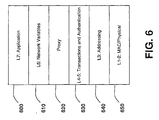
- the proxy layer 620 resides between a transaction/authentication layer 630 and a network variables layer 610. As indicated, these layers roughly correspond to the transport/session layers (L4-5) and the presentation layer (L6) of the Open System Interconnection ("OSI") model.
- OSI Open System Interconnection
- an agent/target transaction may be a different type of transaction from the corresponding repeater/agent transaction.
- the repeater/agent transaction may be a request/response message whereas the agent/target transaction may be a acknowledged message multicast to a group of nodes.
- the response transmitted from the agent to the repeater may be a simple one-byte completion code conveying success or failure of the underlying transaction.
- the agent could send an acknowledged multicast to a group and upon receiving all the acknowledgements, send a "success" response upstream.
- a "failure" response may be sent upstream along with the repeater index of the node detecting the failure.
- message priorities may be defined.
- priority may be strictly inherited. For example, if a proxy source 500 defines a priority, then priority is used by all proxy repeaters 510 and the proxy agent 520.
- authentication like priority, may be inherited.
- each hop may be authenticated separately.
- the first proxy repeater may challenge the proxy source and receive a successful reply before relaying the proxied message on to the next proxy repeater or proxy agent.
- an authentication key may be embedded in a proxy message header for the proxy agent 520 to use when communicating with the proxy target 530. This configuration handles the case where the agent and target have different authentication keys (presumably only temporarily).
- the proxy source 500 ensures that authentication keys are the same in the intermediate points of the proxy chain (e.g., the proxy repeaters 510) before using authentication.
- the proxy agent 520 of one embodiment is capable of using the authentication key only for that outgoing transaction rather than changing its own key.
- the authentication key passed down for such messages may be in the form of a key increment.
- the proxy agent 520 will use its own key and add the key increment to it to derive the proxy target's 530's key. This feature will provide secure authentication without the need for transmitting the authentication key over a non-secure channel.
- each proxy repeater may serve as both a proxy agent and a proxy repeater.
- a proxy repeater identifies an unacknowledged broadcast or group message as the message to be delivered by the proxy agent (by peeking ahead to the end of the proxy header), it first sends the message as if it were a proxy agent and then relays the message on to the next proxy repeater or proxy agent.
- any given node may receive such a multicast more than one time. Therefore, in one embodiment, it is necessary that such multicasts be idempotent.
- proxy repeaters 510 and proxy agent 520 of this embodiment may use the same domain ID as the proxy source 500. Accordingly, proxy repeaters 510 and proxy agents 520 may be commissioned with a domain ID topologically, closest to the proxy source 500 first.
- the proxy source 500 uses unicast (e.g., subnet/node) addressing to communicate with the first proxy repeater 520 (although other addressing modes may be used as well).
- the proxy header used in this embodiment may contain only unicast addresses so all repeater-to-repeater and repeater-to-agent downstream messages are unicast.
- the channel provides two paths, a primary and alternate path, and the path to be used at each hop is encoded on a per-hop basis in the proxy header.
- the proxy source may be supplied with a routing table containing for each unicast address (subnet/node or node ID), a list of repeaters and the agent to use to reach that address (e.g., perhaps a null set), as well as a first choice path to use at each hop.
- the list may contain the set of agents to which the multicast is to be delivered.
- Embodiments of the invention include various steps, which have been described above.
- the steps may be embodied in machine-executable instructions.
- the instructions can be used to cause a general-purpose or special-purpose processor to perform certain steps.
- these steps may be performed by specific hardware components that contain hardwired logic for performing the steps, or by any combination of programmed computer components and custom hardware components.
- Embodiments of the invention may also be provided as a machine-readable medium for storing the machine-executable instructions.
- the machine-readable medium may include, but is not limited to, floppy diskettes, optical disks, CD-ROMs, and magneto-optical disks, ROMs, RAMs, EPROMs, EEPROMs, magnet or optical cards, propagation media or other type of media/machine-readable medium suitable for storing electronic instructions.
- the present invention may be downloaded as a computer program which may be transferred from a remote computer (e.g., a server) to a requesting computer (e.g., a client) by way of data signals embodied in a carrier wave or other propagation medium via a communication link (e.g., a modem or network connection).
- a remote computer e.g., a server
- a requesting computer e.g., a client
- a communication link e.g., a modem or network connection
- Figure 1 illustrates a terrestrial network configuration
- various non-terrestrial configurations such as radio frequency broadcast, satellite broadcast, personal communication services (“PCS”), Global System for Mobile Communications (“GSM”), and cellular (including code division multiple access (“CDMA”) and time division multiple access (“TDMA”)) may be implemented while still complying with the underlying principles of the invention.
- PCS personal communication services
- GSM Global System for Mobile Communications
- CDMA code division multiple access
- TDMA time division multiple access
- one embodiment of the invention employs a heterogeneous network configuration, including both terrestrial and non-terrestrial components.
- the proxy layer is illustrated in Figure 6 between the transaction/authentication layer 630 and the network variables layer 610, alternate embodiments may incorporate the same proxy functionality at other layers in the OSI model.
- the network functions described above are implemented at the network/addressing layer (i.e., OSI layer 3) 640.
- transaction control and authentication would be implemented on an end-to-end basis (i.e., between the proxy source 500 and the proxy target 530) rather than on an individual node-to-node basis as described above.
Abstract
Description
- This invention relates generally to network configuration techniques. More particularly, the invention relates to an improved system and method for selecting repeaters in a data network.
- A "repeater" is a communications device that amplifies or regenerates a data signal in order to extend the transmission distance between two or more nodes. Repeaters are available for both analog and digital signals and are used extensively for long distance transmission.
- The determination as to where repeaters should be configured/positioned within a network is typically based on the network topology. For example, the physical distance between nodes on the network may be used to determine whether a repeater is necessary. Factored into this calculation is the extent to which data signals will degrade through the physical medium interconnecting nodes on the network. Different types of physical media (e.g., twisted pair, coaxial cable, wireless, ... etc) have different signal-loss characteristics.
- In some circumstances, however, network topology may be unknown at the time the network nodes are interconnected. For example, in circumstances where existing power lines are used to support a communications network, distances between network nodes may not be easily determined. As such, repeater positioning must be accomplished manually, through trial-and-error, by measuring signal strength at various points within the network and configuring repeaters as required.
- Accordingly, what is needed is a more efficient system and method for selecting repeaters within a network. What is also needed is a system and method wherein nodes on a network which perform a particular function may configured as repeaters (i.e., in addition to performing that function).
- A system is described comprising: a source node configured to transmit a data packet to a target node across a data network, the source node having a first retry timer set to a first retry time period after which the source node will retransmit a data packet if it has not received an appropriate response to the data packet; and a first intermediate node electrically positioned between the source node and the target node, the first intermediate node having a second retry timer set to a second retry time period after which the first intermediate node will retransmit the data packet if it has not received an appropriate response to the data packet, wherein the first retry time period is longer than the second retry time period.
- A better understanding of the present invention can be obtained from the following detailed description in conjunction with the following drawings, in which:
- FIG. 1 illustrates a network architecture for implementing various embodiments of the invention.
- FIGS. 2a and 2b illustrate one embodiment of a method for selecting repeaters on a network.
- FIG. 3 illustrates signal strength between a plurality of nodes and a master node.
- FIG. 4 illustrates packet addressing according to one embodiment of the invention.
- FIG. 5a illustrates communication between a proxy source, a proxy repeater, a proxy agent and a proxy target according to one embodiment of the invention.
- FIG. 5b illustrates a transaction control between a proxy agent and a proxy target according to one embodiment of the invention.
- FIG. 5c illustrates transaction control between a proxy repeater and a proxy agent according to one embodiment of the invention.
- FIG. 6 illustrates one embodiment of a proxy protocol configured between a transaction/authentication layer (layers 4-5) and a plurality of network variables (layer 6).
-
- This application is a continuation-in-part of U.S. Serial No. 09/610,670, filed July 5, 2000, entitled "A System and Method for Selecting Repeaters."
- In the following description, for the purposes of explanation, numerous specific details are set forth in order to provide a thorough understanding of various embodiments of the invention. It will be apparent, however, to one skilled in the art that the embodiments of the invention may be practiced without some of these specific details. Moreover, in some instances, well-known structures and devices are shown in block diagram form to avoid obscuring the underlying principles of the invention.
- Figure 1 generally depicts a network over which a plurality of
nodes 100, 101-103,111-113,121-125 and 131-134 communicate. In one embodiment, each of the nodes is comprised of a processor (e.g., a microcontroller or a microprocessor) and memory. In addition, each node may be configured to store, process and communicate (internally or with other nodes) code and data using machine-readable media such as magnetic disks, random access memory ("RAM"), read only memory ("ROM"), carrier wave signals, etc. Moreover, while particular embodiments of the invention may be implemented in software, alternative embodiments may implement the functions described herein using any combination of software, firmware and/or hardware. - In one particular embodiment, the
nodes 100, 101-103, 111-113, 121-125 and 131-134 form a distributed control network such as the Lonworks® Network developed by Echelon® Corporation. In this embodiment, each of thenodes 100, 101-103, 111-113, 121-125 and 131-134 may be programmed to perform a specific task. For example, individual nodes may be configured as proximity sensors, switches, motion detectors, relays, motor drives, and/or other types of instruments (e.g., utility meters). The individual nodes of this embodiment may be programmed to work together as a whole to perform a complex control application such as running a manufacturing line or automating a building. It should be noted, however, that the underlying principles of the invention are not limited to any particular type of node or any particular network configuration or application. - Certain embodiments of the invention also employ a proxy communication protocol to extend the communication range of a network channel when it is impractical to use conventional routers to do so. These embodiments may be particularly suited for network media where "breaking" a physical channel into multiple channels via routers is not practical or possible (e.g., radio frequency (RF), power lines, ... etc).
- In one embodiment, certain nodes may be configured/programmed to function as repeaters in addition to the other functions performed by those nodes (some examples of which are set forth above). As illustrated in Figure 1, a
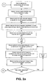
master node 100 may be configured to automatically select surrounding nodes 101-103, 111-113, 121-125 and 131-134 to perform repeater functions based on the detected signal strength at those nodes. In one embodiment, themaster 100 is programmed with device addresses of each of the nodes, which themaster 100 uses to query each of the nodes 101-103, 111-113, 121-125 and 131-134 for signal strength data. After analyzing the signal strength data, themaster 100 selects repeater candidates. - Figures 2a and 2b illustrate one embodiment of a method implemented by a master node to identify repeaters. At 210, the master initially attempts to communicate with all network nodes (e.g., by running through a list of node addresses stored in memory).
- In the illustrated embodiment, the
master node 100 does not merely attempt to communicate but, rather, transmits "return signal strength" query to each of the surrounding nodes. Subsequently (at 215) themaster node 100 receives a response from a subset of the nodes (i.e., from those nodes within the transmission range of the master 100). Each response includes an indication of signal quality when the "return signal strength" query was received at each of the nodes. In addition, in one particular embodiment, themaster node 100 itself evaluates the signal quality of each node's response as it is received by themaster 100. Accordingly, in this embodiment two signal strength values are used by themaster node 100 to evaluate the overall signal strength between it and each node on the network: an outgoing signal strength value (measured at the node); and an incoming signal strength value (measured at the master). The master may consider each value separately, may take the average of the two signal strength values or, alternatively, may weigh one value more heavily than the other. Various other techniques for evaluating the two signal strength values may be employed while still complying with the underlying principles of the invention. - Each of the nodes 101-103, 111-113, 121-125 and 131-134 (including the master 100) may measure "signal strength" using a variety of techniques. For example, in one embodiment, the overall carrier strength (e.g., amplitude) of the transmission is measured. Similarly, the signal-to-noise (S/N) ratio associated with the carrier signal may be calculated (i.e., by tracking the noise on the communication channel before and during the reception of the incoming signal). In addition, in one embodiment, the number of bit errors found in incoming data packet(s) may be calculated and used to provide an indication of the reliability of the communication channel between the node and the master.
- Certain techniques for measuring signal strength may be more appropriate than others depending on network conditions. For example, measuring overall carrier strength may be the most appropriate technique when the noise floor on the channel is below the receiver sensitivity. S/N Ratio may be more useful in cases where the noise on the channel is significant with respect to the signal level, and the number of errors corrected may be useful where other measures of signal strength are not available and/or there is an error correcting code available on the messages.
- In one embodiment, the transmitter signal level may be purposely reduced to test the ability of a node to receive a signal. The transmitter signal level can be used as a measure of signal to noise ratio for the purposes of signal analysis. Use of this technique may require sending additional messages to probe for the level of reception.
- Any of the foregoing signal strength measurement techniques, alone or in combination, may be employed by the nodes to evaluate "signal strength." Moreover, it should be noted that various other techniques may be employed while still complying with the underlying principles of the invention.
- Once the master has collected signal strength values from a subset of all nodes, it performs signal strength analysis (at 220) to determine which nodes in the subset are "first tier" repeater candidates (i.e., those repeaters which will be one transmission length or "hop" away from the master). The master's goal, according to one embodiment, is not to select candidates with the highest measured signal strength but, rather, to select repeater candidates above some minimum (reliable) threshold value, Tmin, and below some maximum threshold value Tmax. In one embodiment, both the outgoing signal strength value (measured at the node) and the incoming signal strength value (measured at the master) must be above the minimum and/or below the maximum threshold value for the particular node to be selected as a repeater.
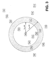
- This concept is highlighted in Figure 3, which illustrates an exemplary signal strength relationship between the
master 100 and the various nodes 101-103, 111-113, 121-125 and 131-134 shown in Figure 1. Nodes which are positioned further away from themaster node 100 in Figure 3 have a relatively lower signal strength value in relation to themaster 100. - In the illustrated embodiment,
nodes master node 100 to select these nodes as repeater candidates, however, because they are not far enough away from themaster node 100 to be useful as repeaters. - By contrast,
nodes 103, 112-113, 124-125 and 132-134 are electronically distant from themaster node 100 and have signal strength values below someminimum threshold value 351. Themaster 100 will not initially select these nodes as repeaters because signal strength is so weak that they may prove to be unreliable. In fact, some or all may not even have received the master's 100 initial signal strength query. - Finally,
nodes maximum threshold value 350 but above theminimum threshold value 351. They are far enough away from themaster 100 to make them efficient selections for repeater candidates, while - at the same time - their signal strength is high enough to indicate that they will be reliable as first tier repeaters. Accordingly, in the illustrated embodiment, themaster node 100 initially selectsnodes - At 225, the
master 100 transmits a "proxy return signal strength" command to each of the newly-selected firsttier repeater candidates nodes master 100 initially attempted to communicate with all nodes at 210), and to communicate the results back to themaster 100. For the purposes of this example, it will be assumed that none of the nodes below theminimum threshold value 351 have responded (i.e.,nodes 103, 112-113, 124-125 and 132-134). - In response to the return signal strength command,
node 102queries node 103 for signal strength data. Subsequently,node 102 receives a response fromnode 103 which includes an indication of signal quality when the signal strength query was received atnode 103. In addition, in one embodiment,node 102 evaluates the signal quality ofnode 103's response as it is received atnode 102. Accordingly, the "proxy return signal strength" command, like the "return signal strength" command, collects an incoming signal strength value (measured at node 102) as well as an outgoing signal strength value (measured at node 103), and transmits the result back to themaster 100. - Similarly, in the illustrated example,
node 123 collects proxy signal strength data fromnode 124 andnode 111 collects proxy signal strength data fromnodes 112 and/or 113. - Once the proxy signal strength data is collected by the first tier repeater candidates, it is transmitted back to the
master node 100 at 230. At 235, a method variable 'N,' which represents the particular tier of nodes under analysis is set equal to two. It should be noted, however, that this initialization is only used for the purpose of describing the underlying process set forth in Figures 2a and 2b. No such variable initialization is required for complying with the underlying principles of the invention. - At 240, the master analyzes the proxy signal strength data to determine which (if any) of the newly-identified nodes should be configured as a second tier repeater. Once again, this decision may be based on where the signal strength values fall within predetermined minimum and maximum signal strength thresholds (as with selection of the first tier of repeaters described above). Thus,
node 112 in the illustrated example may be too close torepeater candidate 111 to be properly selected as a repeater (i.e., signal strength may be above the maximum value) butnode 113 may be a sufficient distance away to make it an ideal repeater candidate (i.e., within both the minimum and maximum threshold requirements). - Once the
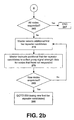
master 100 has identified the second tier (or Nth tier) of repeater candidates, at 245 it instructs each of the nodes in the second tier to collect proxy return signal strength data for nodes that have yet to be identified. At 250, the master receives the latest set of proxy return signal strength data and (if any new nodes have responded, determined at 255) analyzes the data to identify the next (e.g., the third) tier of repeater candidates. The master proceeds through successive tiers in this manner (i.e., tier N=N+1 with each iteration, as set forth in box 257) until no new nodes are identified using the proxy return signal strength commands. At this point, one embodiment of the system and method proceeds to the flowchart illustrated in Figure 2b. - At 265, the master determines whether all nodes on the network have responded. If all nodes are accounted for, then the process is complete at 267 (i.e., all nodes are identified and all repeaters have been assigned). If, however, certain nodes have not responded, then the
master 100 selects additional first tier repeater candidates in an effort to locate these nodes. Accordingly, themaster 100 may select nodes which have signal strength values above thepreset maximum 350. - Returning to the particular example illustrated in Figure 3, the
master 100 may select any or all ofnodes 101, 121-122, and 131 as new first tier candidates. In one embodiment, the master selects nodes at a signal strength value in the vicinity of one half of themaximum threshold value 350, to increase the likelihood of identifying additional nodes. - At 275, the
master 100 instructs the new first tier repeater candidates to collect proxy return signal strength data from any nodes which have not yet responded. Thus, ifnode 131 is selected, it may attempt to collect signal strength data from nodes 132-134; and ifnode 121 is selected, it may attempt to collect signal strength data fromnode 125. The master continues to select new first tier candidates until new nodes have been identified (determined at 280). - Once new nodes respond, the process of searching through successive tiers begins again at 230, where the master receives a new set of proxy return signal strength data from the new first tier repeater candidate(s). The master then works its way through successive tiers as described above until no new nodes are responding (determined at 255). When all nodes have been identified (determined at 265) the process is complete (at 267).
- In one embodiment, the
master node 100 is not initially programmed with device addresses of each of the nodes. Rather, in this embodiment, themaster node 100 transmits a broadcast search message, requesting a response from any nodes within its transmission range. As nodes respond to the broadcast search message, themaster node 100 stores their device addresses and selects certain nodes as repeaters as described above. Once selected by themaster 100, the various repeater candidates may also send broadcast messages to any nodes within their transmission range. - In one embodiment, once a node has responded to a broadcast search message, the master node 100 (or repeater candidate) instructs the node not to respond to any subsequent broadcast search messages. Alternatively, or in addition, the
master node 100 or repeater candidate may simply ignore subsequent responses to broadcast search message responses from nodes which have already responded. - In one embodiment, an address of each intermediate node through which a data packet will pass is included in an address field in the data packet. For example, as illustrated in Figure 4, when the
master 100 transmits adata packet 400 containing a particular command 410 (e.g., a proxy return signal strength command), it includes the addresses of each of the nodes, R1-R3, through which the packet will pass on its way to thedestination node 405. - Similarly, in one embodiment, when the
destination node 405 transmits data 420 (e.g., return signal strength or proxy return signal strength data) in response to the master'scommand 405, it includes an address of each intermediate node, R3-R1, through which the data packet will pass on its way to themaster 100. - It should be noted, however, that various other routing techniques may be implemented while still complying with the underlying principles of the invention. For example, in one embodiment, each node may store a routing table in memory for routing data packets across the network. In this embodiment, only the destination node address (and not the intermediate addresses) is incorporated in the data packet. Each node that receives the data packet in this embodiment checks its routing table to determine the next node to which the packet should be routed (i.e., what the next intermediate node is).
- Embodiments of the system and method described herein may be configured to operate differently depending on the overall size of the network. For example, if the network is small enough so that probing all or most of the nodes does not require an unreasonable amount of time, then the best candidates for repeaters can be identified quickly by using the method set forth in Figures 2a-b.
- However, if the network is large (e.g., above some threshold number of nodes) so that probing most or all the nodes in a reasonable amount of time is not possible, then one embodiment of the system and method can be used to quickly identify repeating nodes so that communications can be established with all nodes. The time/resource advantage of this embodiment is realized because fewer of the communicating nodes need to be probed to identify repeaters for the remaining nodes. In a large network, after communication is established with all nodes, additional available resources can be used to identify better repeater or alternate repeater candidates.
- In one embodiment of the system, repeaters do not separate the physical medium over which they communicate into separate "channels." Rather, in this particular embodiment, repeaters re-transmit data on the same channel on which they receive the data (hereinafter "disconnected channel"). However, it should be noted that the underlying principles of the invention are not limited to any particular type of communication channel.
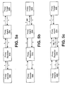
- As illustrated in Figures 5a through 5c, in one embodiment, nodes may be configured as
proxy sources 500,proxy repeaters 510,proxy agents 520, and/or proxy targets 530. Generally speaking, aproxy source 500 communicates with aproxy target 520 through aproxy repeater 510 and/or aproxy agent 520. In one embodiment, node designations occur automatically, after the nodes have been physically connected to the network (e.g., as described above with respect to repeater selection). - A
proxy source 500 is any node originating a proxy transaction. In one embodiment, theproxy source 500 generates a proxy operation by attaching a proxy header to a standard (i.e., non-proxy) data/command packet. One example of a standard data/command packet is a command requesting the value of a particular variable at a target node. If the target node is within transmission range of the source node (i.e., if no hops are required through intermediate nodes), then the source node simply transmits the packet directly to the target using the target's network address and waits for the response. If, however, the target node is outside of the source node's transmission range, then in one embodiment, the source attaches a proxy header to the packet, indicating one or more intermediate nodes (e.g., theproxy repeater 510 and the proxy agent 520) through which the data/command packet must pass to arrive at the target node (or in this case the "proxy" target node 530). - Any nodes which are electrically positioned between the
proxy source 500 andproxy agent 520 may be configured asproxy repeaters 510. In one embodiment, when aproxy repeater 510 receives a data/command packet directed to theproxy target 530 it relays the message on to the next proxy repeater, or to the proxy agent 520 (if it is thelast proxy repeater 510 in the chain). - A
proxy agent 520 is any node which communicates directly with theproxy target 530. In one embodiment, theproxy agent 520 transmits a standard data/command packet to theproxy target 530, rather than a proxy packet (i.e., one with a "proxy" header). - Once the command has been received and processed at the
proxy target 530, it generates a response packet addressed to theproxy agent 520 containing the data requested by theproxy source 500. Theproxy agent 520 forwards the message to the proxy repeater 510 (by attaching the proxy repeater's address to the packet) which, in turn, forwards the message to theproxy source 500. - It should be noted that various packet addressing and routing techniques may be implemented between the various nodes illustrated in Figures 5a-c while still complying with the underlying principles of the invention. For example, in one embodiment, a packet transmitted by the
proxy source 500 includes an address header with an address of each node through which the packet must pass to arrive at theproxy target 530. Each node in the transmission path receives the packet, strips its own address from the header and forwards the packet on to the next node in the path (identified by the next address in the header). Each node remembers (i.e., stores in memory) the address of the node from which it received the packet. - After processing the packet (e.g., executing the command and collecting any requested data) the
proxy target 530 transmits a response packet back to theproxy agent 520. In one embodiment, the response packet includes only the proxy agent's 520's address. Theproxy agent 520, which previously stored the address of theproxy repeater 510 in memory, uses this address to forward the packet back to theproxy repeater 510; which, in turn, transmits the packet to theproxy source 500 using the address of theproxy source 500 which theproxy repeater 510 previously stored in memory. - In contrast to the foregoing addressing/routing scheme, in one embodiment, addresses are not stripped from data packets as they pass from one node to the next. Rather, in this embodiment, a packet is transmitted from the
proxy source 500 through to theproxy target 530 with an address of each node in the transmission path embedded in the packet's header. In one embodiment, the packet's header also includes a counter/pointer value which points to the next address in the transmission path. Each node that receives the packet increments (or decrements, depending on the particular algorithm) the counter/pointer value so that it points the next address in the packet's header. In one embodiment, when theproxy target 530 receives the packet, it resets the counter and transmits a response packet containing each node address (e.g., in reverse order). - It should be noted that various other addressing and/or routing techniques may be implemented while still complying with the underlying principles of the invention.
- Various transaction control mechanisms may be employed to provide reliable message transmission between network nodes. For example, a node may retransmit a data/command packet if it does not receive a response for a predetermined period of time. Thus, as illustrated in Figure 5b, if a message (3) between the
proxy agent 520 andproxy target 530 is blocked (e.g., due to interference on the network), theproxy agent 520 will retransmit the message (4) if it does not receive a response from theproxy target 530 after a predefined period of time. As described below, in one embodiment, the retry timing (i.e., the timing for retransmitting a lost message) employed at each of the nodes is highly configurable and can be programmed based on a variety of network variables (e.g., the number of hops between the node and theproxy source 500 and/or proxy target 530). - Different timing variables may be used for the retransmission of proxy messages than those used for standard (i.e., non-proxy) messages. For example, in Figure 5b, the
proxy agent 520 may use conventional timer and retry values to communicate with the proxy target 530 (e.g., 3 retries spaced at 192 milliseconds on a contention-free channel), whereas theproxy repeater 510 may use different proxy timer and retry values to communicate with theproxy agent 520 and/or the proxy source 500 (e.g., 6 retries spaced at 960 milliseconds). In one embodiment, the transaction control values to be used for retransmitting a particular message are specified by theproxy source 500 in the data/control packet message header (e.g., the proxy portion of the header). - In one embodiment, the set of control values used at the
proxy source 500 and/orproxy repeater 510 specify an increased number of retries relative to the number of retries specified for theproxy agent 520. For example, the number of retries may be configured to increase with increasing distance from theproxy agent 520. - In one particular embodiment, the
proxy source 500 provides the proxy repeaters with the number of retries for the last repeater to use. Each repeater prior to the last simply uses one more retry than the next. This value may be computed by adding the remaining repeater count to the retry count. - As described above, each of the network nodes may be configured with different retry timer values. In one embodiment, however, the same retry timer value is used for each of the
proxy repeaters 510. The timer value used in this embodiment may be set to be longer than the entire transaction time of the agent/target transaction plus the round trip back to the source. For example, if the agent/target transaction used 3 retries spaced at 192 milliseconds and there is one repeater, then the proxy source/repeater may be programmed to wait approximately 1 second before retrying (i.e., 4*192 = 768 msec to include the initial attempt plus 3 retries; then add 2*100 = 200 msec for 1 proxy repeater at 100 msec per hop with 2 hops total, for a total sum of 200+768=968 msec). - Various data service levels may be defined to operate within the system described herein. These include, but are not limited to, an unacknowledged message service ("unackd") where messages transmitted from a source node to a target node do not require a response from the target; an unacknowledged repeat message service ("unackd-rpt") which is an unacknowledged message transmitted a specified number of times; an acknowledged message ("ackd") wherein the source waits for a simple acknowledgement (or confirmation) transmitted from the target node after receipt of the message; and a request/response message ("request/response") wherein the source waits for a response containing data related to the actual processing of the request in the target node. It should be noted, however, that various additional message service types may be employed while still complying with the underlying principles of the invention.
- Note that when a response is lost on a disconnected channel, message collisions are avoided by virtue of the fact that all the nodes' retry timers are out of sync by the packet propagation delay time between them.
- Figure 5b illustrates an exemplary message sequence when a transmission error occurs between the
proxy agent 520 and theproxy target 530. More particularly,message 3 is lost on its way from theproxy agent 520 to theproxy target 530. Theproxy agent 520, after not receiving a response from theproxy target 530 for a predefined retry time period, retransmits the message (message 4) and receives a response (message 5). Theproxy repeater 510 in this embodiment does not retransmitmessage 2 while waiting formessage 6 because its retry timer is set to a longer period than the proxy agent's 520's. - Figure 5c illustrates an exemplary message sequence in when an intermediate response (message 5) transmitted from the
proxy agent 520 to theproxy repeater 510 is lost. Theproxy repeater 510 transmits message 2 (e.g., a request/response message) to theproxy agent 520 and, after waiting for a response for the retry time period, retransmits the message (illustrated as message 7). Theproxy agent 520 then retransmits the response message (message 8) to theproxy repeater 510. - As described in greater detail below, nodes may be programmed to store messages and message responses in memory. Thus, in Figure 5c, when the
proxy repeater 510 retransmits its message (message 7), theproxy agent 520 can immediately retransmit the response (message 8) which it previously stored in memory. - It should be noted that, in the foregoing example,
message 6 is superfluous, but harmless (i.e., theproxy repeater 510 may be configured to ignore it). In one embodiment, the proxy source's 500's retry timer may be set long enough to prevent this re-transmission. However, exponentially increasing retry timers in this manner may become problematic in certain situations (e.g., with a large number of repeaters). - For request/response transactions carried out under one embodiment, although the response packet relayed upstream will be identical to that originally sent by the
proxy target 530, the source address of the response received by theproxy source 500 from thefirst repeater 510 will be that of the repeater, not theproxy target 530. - In one embodiment, each proxy repeater/agent buffers any responses it receives. This way, if a response is lost in transmission (e.g.,
message 5 of Figure 5c), and a request retry is received, it will not be necessary to re-fetch the response from the downstream path. - In one embodiment, this buffering feature is accomplished at a proxy layer configured in the network protocol stack. As illustrated in Figure 6, in one embodiment, the
proxy layer 620 resides between a transaction/authentication layer 630 and anetwork variables layer 610. As indicated, these layers roughly correspond to the transport/session layers (L4-5) and the presentation layer (L6) of the Open System Interconnection ("OSI") model. - In one embodiment, an agent/target transaction may be a different type of transaction from the corresponding repeater/agent transaction. For example, the repeater/agent transaction may be a request/response message whereas the agent/target transaction may be a acknowledged message multicast to a group of nodes. In this embodiment, the response transmitted from the agent to the repeater may be a simple one-byte completion code conveying success or failure of the underlying transaction. For example, the agent could send an acknowledged multicast to a group and upon receiving all the acknowledgements, send a "success" response upstream. Similarly, if the agent/target transaction is request/response and no response is received, a "failure" response may be sent upstream along with the repeater index of the node detecting the failure.
- In an embodiment in which contention-based channels are used, message priorities may be defined. For example, a
proxy source 500 may define a priority level (e.g., priority = 1, 2, 3, ... etc) for each message it generates. In one embodiment, priority may be strictly inherited. For example, if aproxy source 500 defines a priority, then priority is used by allproxy repeaters 510 and theproxy agent 520. - Various authentication techniques may be implemented to provide for secure message transmission across the network. In one embodiment, authentication, like priority, may be inherited. In this embodiment, each hop may be authenticated separately. For example, the first proxy repeater may challenge the proxy source and receive a successful reply before relaying the proxied message on to the next proxy repeater or proxy agent.
- In one embodiment, in order to support changing of authentication keys, an authentication key may be embedded in a proxy message header for the
proxy agent 520 to use when communicating with theproxy target 530. This configuration handles the case where the agent and target have different authentication keys (presumably only temporarily). In one embodiment, theproxy source 500 ensures that authentication keys are the same in the intermediate points of the proxy chain (e.g., the proxy repeaters 510) before using authentication. Theproxy agent 520 of one embodiment is capable of using the authentication key only for that outgoing transaction rather than changing its own key. - The authentication key passed down for such messages may be in the form of a key increment. In other words, the
proxy agent 520 will use its own key and add the key increment to it to derive the proxy target's 530's key. This feature will provide secure authentication without the need for transmitting the authentication key over a non-secure channel. - In one embodiment, unacknowledged broadcast and group messages are handled in a special way. In this case, each proxy repeater may serve as both a proxy agent and a proxy repeater. When a proxy repeater identifies an unacknowledged broadcast or group message as the message to be delivered by the proxy agent (by peeking ahead to the end of the proxy header), it first sends the message as if it were a proxy agent and then relays the message on to the next proxy repeater or proxy agent.
- Note that any given node may receive such a multicast more than one time. Therefore, in one embodiment, it is necessary that such multicasts be idempotent.
- In one embodiment, a single domain scheme is used. Thus, the
proxy repeaters 510 andproxy agent 520 of this embodiment may use the same domain ID as theproxy source 500. Accordingly,proxy repeaters 510 andproxy agents 520 may be commissioned with a domain ID topologically, closest to theproxy source 500 first. - In one embodiment, the
proxy source 500 uses unicast (e.g., subnet/node) addressing to communicate with the first proxy repeater 520 (although other addressing modes may be used as well). The proxy header used in this embodiment may contain only unicast addresses so all repeater-to-repeater and repeater-to-agent downstream messages are unicast. - Some types of media provide multiple paths over which to transmit. For example, multiple frequency bands might be used for transmission, some more likely to function than others depending on types of interference. In one embodiment, the channel provides two paths, a primary and alternate path, and the path to be used at each hop is encoded on a per-hop basis in the proxy header.
- The proxy source may be supplied with a routing table containing for each unicast address (subnet/node or node ID), a list of repeaters and the agent to use to reach that address (e.g., perhaps a null set), as well as a first choice path to use at each hop. For multicast addresses, the list may contain the set of agents to which the multicast is to be delivered.
- Embodiments of the invention include various steps, which have been described above. The steps may be embodied in machine-executable instructions. The instructions can be used to cause a general-purpose or special-purpose processor to perform certain steps. Alternatively, these steps may be performed by specific hardware components that contain hardwired logic for performing the steps, or by any combination of programmed computer components and custom hardware components.
- Embodiments of the invention may also be provided as a machine-readable medium for storing the machine-executable instructions. The machine-readable medium may include, but is not limited to, floppy diskettes, optical disks, CD-ROMs, and magneto-optical disks, ROMs, RAMs, EPROMs, EEPROMs, magnet or optical cards, propagation media or other type of media/machine-readable medium suitable for storing electronic instructions. For example, the present invention may be downloaded as a computer program which may be transferred from a remote computer (e.g., a server) to a requesting computer (e.g., a client) by way of data signals embodied in a carrier wave or other propagation medium via a communication link (e.g., a modem or network connection).
- Throughout the foregoing description, for the purpose of explanation, numerous specific details were set forth in order to provide a thorough understanding of the invention. It will be apparent, however, to one skilled in the art that the invention may be practiced without some of these specific details.
- For example, while Figure 1 illustrates a terrestrial network configuration, various non-terrestrial configurations such as radio frequency broadcast, satellite broadcast, personal communication services ("PCS"), Global System for Mobile Communications ("GSM"), and cellular (including code division multiple access ("CDMA") and time division multiple access ("TDMA")) may be implemented while still complying with the underlying principles of the invention. Moreover, one embodiment of the invention employs a heterogeneous network configuration, including both terrestrial and non-terrestrial components.
- Similarly, although the proxy layer is illustrated in Figure 6 between the transaction/
authentication layer 630 and thenetwork variables layer 610, alternate embodiments may incorporate the same proxy functionality at other layers in the OSI model. For example, in one embodiment, the network functions described above are implemented at the network/addressing layer (i.e., OSI layer 3) 640. In this embodiment, transaction control and authentication would be implemented on an end-to-end basis (i.e., between theproxy source 500 and the proxy target 530) rather than on an individual node-to-node basis as described above. - Thus, the scope and spirit of the invention should be judged in terms of the claims which follow.
Claims (22)
- A system comprising:wherein said first retry time period is longer than said second retry time period.a source node configured to transmit a data packet to a target node across a data network, said source node having a first retry timer set to a first retry time period after which said source node will retransmit a data packet if it has not received an appropriate response to said data packet; anda first intermediate node electrically positioned between said source node and said target node, said first intermediate node having a second retry timer set to a second retry time period after which said first intermediate node will retransmit said data packet if it has not received an appropriate response to said data packet,
- The system as in claim 1 further comprising:wherein said third retry time period is shorter than said second retry time period.a second intermediate node electrically positioned between first intermediate node and said target node, said second intermediate node having a third retry timer set to a third retry time period after which said second intermediate node will retransmit said data packet if it has not received an appropriate response to said data packet,
- The system of claim 2 wherein said first, second and third retry timers are set by said data packet transmitted from said source node.
- The system of claim 1 wherein said source node is configured to retransmit said data packet a first predetermined number of times if it has not received an appropriate response to said data packet.
- The system of claim 4 wherein said intermediate node is configured to retransmit said data packet a second predetermined number of times if it has not received an appropriate response to said data packet.
- The system of claim 5 wherein said first predetermined number of times is greater than said second predetermined number of times.
- The system of claim 2 wherein said second intermediate node is a proxy agent and said first intermediate node is a proxy repeater.
- A system for providing proxy communication for a standard set of network commands comprising:a source node attaching a proxy header to a packet in which one of said standard network commands is encapsulated, said proxy header identifying an agent node,said agent node, upon receipt of said packet with said proxy header, communicating with a target node using said standard network command.
- The system as in claim 8 further comprising:a first repeater node electrically positioned between said agent node and said source node, said first repeater node to forward said packet with said proxy header to said agent node.
- The system as in claim 9 wherein said first repeater node is configured to remove its address from said proxy header before forwarding said packet.
- The system as in claim 9 further comprising:a second repeater node electrically positioned between said source node and said first repeater node, said second repeater node configured to forward said packet to said first repeater node.
- The system as in claim 11 wherein said second repeater node is configured to remove its address from said proxy header before forwarding said packet on to said first repeater node.
- The system as in claim 9 wherein said first repeater is further configured to store address data for a return path to said source node, said address data used for forwarding said target node's response to said packet.
- The system as in claim 11 wherein said second repeater is further configured to store address data for a return path to said source node, said address data used for forwarding said target node's response to said packet.
- The system as in claim 8 wherein said standard network command is a request/response command.
- A method for providing transaction control between a source node and a target node, said source node and said target node communicating across one or more repeater nodes, the method comprising:wherein said first time period is longer than said second time period.transmitting a data command from said source node to a first repeater node, said first repeater node configured to transmit said data command to said target node;retransmitting said data command from said source node to said first repeater node if said source node has not received an appropriate response within a first time period; andretransmitting said data command from said first repeater node to said target node if said first repeater node has not received an appropriate response from said target node within a second time period,
- The method as in claim 16 further comprising:wherein said third time period is shorter than said second time period.transmitting said data command from said first repeater node to a second repeater node, said second repeater node configured to transmit said data command to said target node;retransmitting said data command from said second repeater node to said target node if said second repeater node has not received an appropriate response to said data command within a third time period,
- The method of claim 17 wherein said first, second and third time periods are set by said data packet transmitted from said source node.
- The system of claim 16 wherein said source node is configured to retransmit said data packet to said first repeater node a first predetermined number of times if it has not received an appropriate response to said data packet.
- The system of claim 16 wherein said first repeater node is configured to retransmit said data packet to said target node a second predetermined number of times if it has not received an appropriate response to said data packet.
- The system of claim 20 wherein said first predetermined number of times is greater than said second predetermined number of times.
- The system of claim 17 wherein said second repeater node is a proxy agent and said first repeater node is a proxy repeater.
Applications Claiming Priority (2)
| Application Number | Priority Date | Filing Date | Title |
|---|---|---|---|
| US638169 | 2000-08-11 | ||
| US09/638,169 US7103016B1 (en) | 2000-08-11 | 2000-08-11 | System and method for providing transaction control on a data network |
Publications (3)
| Publication Number | Publication Date |
|---|---|
| EP1179909A2 true EP1179909A2 (en) | 2002-02-13 |
| EP1179909A3 EP1179909A3 (en) | 2004-01-28 |
| EP1179909B1 EP1179909B1 (en) | 2018-02-14 |
Family
ID=24558922
Family Applications (1)
| Application Number | Title | Priority Date | Filing Date |
|---|---|---|---|
| EP01303672.8A Expired - Lifetime EP1179909B1 (en) | 2000-08-11 | 2001-04-20 | A system and method for providing transaction control on a data network |
Country Status (2)
| Country | Link |
|---|---|
| US (1) | US7103016B1 (en) |
| EP (1) | EP1179909B1 (en) |
Cited By (3)
| Publication number | Priority date | Publication date | Assignee | Title |
|---|---|---|---|---|
| WO2006024320A1 (en) * | 2004-08-31 | 2006-03-09 | Telefonaktiebolaget Lm Ericsson (Publ) | Data unit sender and data unit relay device |
| RU2541194C2 (en) * | 2010-06-14 | 2015-02-10 | Интел Корпорейшн | Beacon transmission methods in directional wireless communication networks |
| US9001921B1 (en) | 2004-02-18 | 2015-04-07 | Marvell International Ltd. | Circuits, architectures, methods, algorithms, software, and systems for improving the reliability of data communications having time-dependent fluctuations |
Families Citing this family (64)
| Publication number | Priority date | Publication date | Assignee | Title |
|---|---|---|---|---|
| US6862430B1 (en) * | 2000-07-05 | 2005-03-01 | Echelon Corporation | System and method for selecting repeaters |
| GB2378781B (en) * | 2001-08-16 | 2005-06-01 | Sun Microsystems Inc | Message brokering |
| GB2378782B (en) * | 2001-08-16 | 2005-04-13 | Sun Microsystems Inc | Message brokering |
| US7009530B2 (en) * | 2001-09-13 | 2006-03-07 | M&Fc Holding, Llc | Modular wireless fixed network for wide-area metering data collection and meter module apparatus |
| JP4053269B2 (en) * | 2001-09-27 | 2008-02-27 | 株式会社東芝 | Data transfer apparatus and data transfer method |
| US7142107B2 (en) | 2004-05-27 | 2006-11-28 | Lawrence Kates | Wireless sensor unit |
| EP1905200A1 (en) | 2005-07-01 | 2008-04-02 | Terahop Networks, Inc. | Nondeterministic and deterministic network routing |
| US8688856B2 (en) * | 2006-01-24 | 2014-04-01 | Novell, Inc. | Techniques for managing a network delivery path of content via a key |
| US8312103B2 (en) * | 2006-08-31 | 2012-11-13 | Itron, Inc. | Periodic balanced communication node and server assignment |
| US20080074285A1 (en) * | 2006-08-31 | 2008-03-27 | Guthrie Kevin D | Interface between meter and application (IMA) |
| US20080071930A1 (en) * | 2006-09-01 | 2008-03-20 | Holbrook Kenneth J | Native network transport |
| KR101424592B1 (en) * | 2007-10-19 | 2014-07-31 | 삼성전자주식회사 | Logical connection establishment method of portable terminal |
| WO2009151877A2 (en) | 2008-05-16 | 2009-12-17 | Terahop Networks, Inc. | Systems and apparatus for securing a container |
| US8694164B2 (en) | 2008-10-27 | 2014-04-08 | Lennox Industries, Inc. | Interactive user guidance interface for a heating, ventilation and air conditioning system |
| US9651925B2 (en) | 2008-10-27 | 2017-05-16 | Lennox Industries Inc. | System and method for zoning a distributed-architecture heating, ventilation and air conditioning network |
| US9261888B2 (en) | 2008-10-27 | 2016-02-16 | Lennox Industries Inc. | System and method of use for a user interface dashboard of a heating, ventilation and air conditioning network |
| US8437877B2 (en) | 2008-10-27 | 2013-05-07 | Lennox Industries Inc. | System recovery in a heating, ventilation and air conditioning network |
| US8295981B2 (en) | 2008-10-27 | 2012-10-23 | Lennox Industries Inc. | Device commissioning in a heating, ventilation and air conditioning network |
| US8762666B2 (en) | 2008-10-27 | 2014-06-24 | Lennox Industries, Inc. | Backup and restoration of operation control data in a heating, ventilation and air conditioning network |
| US8463442B2 (en) | 2008-10-27 | 2013-06-11 | Lennox Industries, Inc. | Alarm and diagnostics system and method for a distributed architecture heating, ventilation and air conditioning network |
| US9268345B2 (en) | 2008-10-27 | 2016-02-23 | Lennox Industries Inc. | System and method of use for a user interface dashboard of a heating, ventilation and air conditioning network |
| US8564400B2 (en) | 2008-10-27 | 2013-10-22 | Lennox Industries, Inc. | Communication protocol system and method for a distributed-architecture heating, ventilation and air conditioning network |
| US8442693B2 (en) | 2008-10-27 | 2013-05-14 | Lennox Industries, Inc. | System and method of use for a user interface dashboard of a heating, ventilation and air conditioning network |
| US8977794B2 (en) | 2008-10-27 | 2015-03-10 | Lennox Industries, Inc. | Communication protocol system and method for a distributed-architecture heating, ventilation and air conditioning network |
| US8661165B2 (en) | 2008-10-27 | 2014-02-25 | Lennox Industries, Inc. | Device abstraction system and method for a distributed architecture heating, ventilation and air conditioning system |
| US8725298B2 (en) | 2008-10-27 | 2014-05-13 | Lennox Industries, Inc. | Alarm and diagnostics system and method for a distributed architecture heating, ventilation and conditioning network |
| US8788100B2 (en) | 2008-10-27 | 2014-07-22 | Lennox Industries Inc. | System and method for zoning a distributed-architecture heating, ventilation and air conditioning network |
| US9678486B2 (en) | 2008-10-27 | 2017-06-13 | Lennox Industries Inc. | Device abstraction system and method for a distributed-architecture heating, ventilation and air conditioning system |
| US8239066B2 (en) | 2008-10-27 | 2012-08-07 | Lennox Industries Inc. | System and method of use for a user interface dashboard of a heating, ventilation and air conditioning network |
| US8352081B2 (en) | 2008-10-27 | 2013-01-08 | Lennox Industries Inc. | Communication protocol system and method for a distributed-architecture heating, ventilation and air conditioning network |
| US8994539B2 (en) | 2008-10-27 | 2015-03-31 | Lennox Industries, Inc. | Alarm and diagnostics system and method for a distributed-architecture heating, ventilation and air conditioning network |
| US8352080B2 (en) | 2008-10-27 | 2013-01-08 | Lennox Industries Inc. | Communication protocol system and method for a distributed-architecture heating, ventilation and air conditioning network |
| US8798796B2 (en) | 2008-10-27 | 2014-08-05 | Lennox Industries Inc. | General control techniques in a heating, ventilation and air conditioning network |
| US8452456B2 (en) | 2008-10-27 | 2013-05-28 | Lennox Industries Inc. | System and method of use for a user interface dashboard of a heating, ventilation and air conditioning network |
| US8433446B2 (en) | 2008-10-27 | 2013-04-30 | Lennox Industries, Inc. | Alarm and diagnostics system and method for a distributed-architecture heating, ventilation and air conditioning network |
| US8802981B2 (en) | 2008-10-27 | 2014-08-12 | Lennox Industries Inc. | Flush wall mount thermostat and in-set mounting plate for a heating, ventilation and air conditioning system |
| US8655491B2 (en) | 2008-10-27 | 2014-02-18 | Lennox Industries Inc. | Alarm and diagnostics system and method for a distributed architecture heating, ventilation and air conditioning network |
| US8874815B2 (en) | 2008-10-27 | 2014-10-28 | Lennox Industries, Inc. | Communication protocol system and method for a distributed architecture heating, ventilation and air conditioning network |
| US8600559B2 (en) | 2008-10-27 | 2013-12-03 | Lennox Industries Inc. | Method of controlling equipment in a heating, ventilation and air conditioning network |
| US8255086B2 (en) | 2008-10-27 | 2012-08-28 | Lennox Industries Inc. | System recovery in a heating, ventilation and air conditioning network |
| US8543243B2 (en) | 2008-10-27 | 2013-09-24 | Lennox Industries, Inc. | System and method of use for a user interface dashboard of a heating, ventilation and air conditioning network |
| US9325517B2 (en) | 2008-10-27 | 2016-04-26 | Lennox Industries Inc. | Device abstraction system and method for a distributed-architecture heating, ventilation and air conditioning system |
| US8892797B2 (en) | 2008-10-27 | 2014-11-18 | Lennox Industries Inc. | Communication protocol system and method for a distributed-architecture heating, ventilation and air conditioning network |
| US8855825B2 (en) | 2008-10-27 | 2014-10-07 | Lennox Industries Inc. | Device abstraction system and method for a distributed-architecture heating, ventilation and air conditioning system |
| US9152155B2 (en) | 2008-10-27 | 2015-10-06 | Lennox Industries Inc. | Device abstraction system and method for a distributed-architecture heating, ventilation and air conditioning system |
| US9632490B2 (en) | 2008-10-27 | 2017-04-25 | Lennox Industries Inc. | System and method for zoning a distributed architecture heating, ventilation and air conditioning network |
| US8560125B2 (en) | 2008-10-27 | 2013-10-15 | Lennox Industries | Communication protocol system and method for a distributed-architecture heating, ventilation and air conditioning network |
| US8463443B2 (en) | 2008-10-27 | 2013-06-11 | Lennox Industries, Inc. | Memory recovery scheme and data structure in a heating, ventilation and air conditioning network |
| US9432208B2 (en) | 2008-10-27 | 2016-08-30 | Lennox Industries Inc. | Device abstraction system and method for a distributed architecture heating, ventilation and air conditioning system |
| US8774210B2 (en) | 2008-10-27 | 2014-07-08 | Lennox Industries, Inc. | Communication protocol system and method for a distributed-architecture heating, ventilation and air conditioning network |
| US8655490B2 (en) | 2008-10-27 | 2014-02-18 | Lennox Industries, Inc. | System and method of use for a user interface dashboard of a heating, ventilation and air conditioning network |
| US8600558B2 (en) | 2008-10-27 | 2013-12-03 | Lennox Industries Inc. | System recovery in a heating, ventilation and air conditioning network |
| US9377768B2 (en) | 2008-10-27 | 2016-06-28 | Lennox Industries Inc. | Memory recovery scheme and data structure in a heating, ventilation and air conditioning network |
| US8437878B2 (en) | 2008-10-27 | 2013-05-07 | Lennox Industries Inc. | Alarm and diagnostics system and method for a distributed architecture heating, ventilation and air conditioning network |
| US8452906B2 (en) | 2008-10-27 | 2013-05-28 | Lennox Industries, Inc. | Communication protocol system and method for a distributed-architecture heating, ventilation and air conditioning network |
| US8744629B2 (en) | 2008-10-27 | 2014-06-03 | Lennox Industries Inc. | System and method of use for a user interface dashboard of a heating, ventilation and air conditioning network |
| US8615326B2 (en) | 2008-10-27 | 2013-12-24 | Lennox Industries Inc. | System and method of use for a user interface dashboard of a heating, ventilation and air conditioning network |
| US8548630B2 (en) | 2008-10-27 | 2013-10-01 | Lennox Industries, Inc. | Alarm and diagnostics system and method for a distributed-architecture heating, ventilation and air conditioning network |
| USD648642S1 (en) | 2009-10-21 | 2011-11-15 | Lennox Industries Inc. | Thin cover plate for an electronic system controller |
| USD648641S1 (en) | 2009-10-21 | 2011-11-15 | Lennox Industries Inc. | Thin cover plate for an electronic system controller |
| US8260444B2 (en) | 2010-02-17 | 2012-09-04 | Lennox Industries Inc. | Auxiliary controller of a HVAC system |
| US10200476B2 (en) | 2011-10-18 | 2019-02-05 | Itron, Inc. | Traffic management and remote configuration in a gateway-based network |
| JP2013219608A (en) * | 2012-04-10 | 2013-10-24 | Canon Inc | Information processing apparatus, control method for information processing apparatus, and program |
| RU2649788C1 (en) * | 2016-06-16 | 2018-04-04 | Общество С Ограниченной Ответственностью "Яндекс" | Method and system for transaction request processing in distributed data processing systems |
Citations (1)
| Publication number | Priority date | Publication date | Assignee | Title |
|---|---|---|---|---|
| US5699367A (en) | 1995-12-29 | 1997-12-16 | Telefonaktiebolaget Lm Ericsson | Concatenated error detection coding and packet numbering for hierarchical ARQ schemes |
Family Cites Families (27)
| Publication number | Priority date | Publication date | Assignee | Title |
|---|---|---|---|---|
| US4270029A (en) | 1978-03-23 | 1981-05-26 | Kokusai Denshin Denwa Kabushiki Kaisha | Selection system for digital signal repeaters |
| US5422929A (en) | 1991-11-13 | 1995-06-06 | Txport, Inc. | Telephone line repeater and method of testing same |
| GB9223890D0 (en) * | 1992-11-13 | 1993-01-06 | Ncr Int Inc | Wireless local area network system |
| US5341398A (en) | 1993-02-25 | 1994-08-23 | Motorola, Inc. | Method for repeaters to adaptively digitally code received analog information |
| US5457687A (en) * | 1993-09-02 | 1995-10-10 | Network Equipment Technologies, Inc. | Method and apparatus for backward explicit congestion notification (BECN) in an ATM network |
| WO1996017462A2 (en) * | 1994-11-21 | 1996-06-06 | Oracle Corporation | A reliable connectionless network protocol |
| US5793842A (en) | 1995-02-27 | 1998-08-11 | Schloemer; Jerry R. | System and method of call routing and connection in a mobile (remote) radio telephone system |
| US6621833B1 (en) * | 1999-12-17 | 2003-09-16 | World Com, Inc. | Method and system for efficiently passing the silence or unused status of a DSO channel through a DSO switch matrix and a data switch |
| JPH08307442A (en) * | 1995-05-12 | 1996-11-22 | Toshiba Corp | Data transfer system |
| US5815667A (en) * | 1995-11-28 | 1998-09-29 | Ncr Corporation | Circuits and methods for intelligent acknowledgement based flow control in a processing system network |
| US5822523A (en) * | 1996-02-01 | 1998-10-13 | Mpath Interactive, Inc. | Server-group messaging system for interactive applications |
| US5883884A (en) | 1996-04-22 | 1999-03-16 | Roger F. Atkinson | Wireless digital communication system having hierarchical wireless repeaters with autonomous hand-off |
| US5917820A (en) * | 1996-06-10 | 1999-06-29 | Cisco Technology, Inc. | Efficient packet forwarding arrangement for routing packets in an internetwork |
| US5905871A (en) * | 1996-10-10 | 1999-05-18 | Lucent Technologies Inc. | Method of multicasting |
| US5850605A (en) | 1996-11-05 | 1998-12-15 | Motorola, Inc. | Method and apparatus for dynamically grouping transmitters for message transmission in a communication system |
| US5878352A (en) | 1996-12-20 | 1999-03-02 | Motorola, Inc. | Apparatus and method for selecting a transmitter for directed message delivery |
| US5920818A (en) | 1996-12-03 | 1999-07-06 | Telefonaktiebolaget L M Ericsson (Publ) | Apparatus and method for controlling communications in a multi-network, wireless communication system |
| US6181704B1 (en) * | 1997-08-29 | 2001-01-30 | Intel Corporation | Method and apparatus for input/output link retry, failure and recovery in a computer network |
| US6125279A (en) | 1998-01-07 | 2000-09-26 | Motorola, Inc. | Method and apparatus for extending coverage in a cellular communication system |
| US6507562B1 (en) * | 1998-06-30 | 2003-01-14 | Sun Microsystems, Inc. | Dynamic optimization for receivers using distance between a repair head and a member station in a repair group for receivers having a closely knit topological arrangement to locate repair heads near the member stations which they serve in tree based repair in reliable multicast protocol |
| US6515994B1 (en) * | 1998-07-30 | 2003-02-04 | Lucent Technologies Inc. | Method of communication in a communications network and apparatus therefor |
| US6459899B1 (en) | 1998-09-14 | 2002-10-01 | Jerry R. Schloemer | Cellular radio routing system |
| US6269080B1 (en) * | 1999-04-13 | 2001-07-31 | Glenayre Electronics, Inc. | Method of multicast file distribution and synchronization |
| US6377805B1 (en) | 1999-08-04 | 2002-04-23 | International Business Machines Corporation | Maintaining data communication through neighboring mobile units during handoff |
| US6587974B1 (en) * | 1999-11-19 | 2003-07-01 | Tyco Telecommunications (Us) Inc. | Method for fault detection and fast protection switching in transmission systems |
| US6466905B1 (en) | 1999-11-30 | 2002-10-15 | Motorola, Inc. | Differentiation of error conditions in digital voice communication systems |
| US6687509B2 (en) | 1999-12-29 | 2004-02-03 | Airnet Communications Corporation | Backhaul power control system in a wireless repeater |
-
2000
- 2000-08-11 US US09/638,169 patent/US7103016B1/en not_active Expired - Lifetime
-
2001
- 2001-04-20 EP EP01303672.8A patent/EP1179909B1/en not_active Expired - Lifetime
Patent Citations (1)
| Publication number | Priority date | Publication date | Assignee | Title |
|---|---|---|---|---|
| US5699367A (en) | 1995-12-29 | 1997-12-16 | Telefonaktiebolaget Lm Ericsson | Concatenated error detection coding and packet numbering for hierarchical ARQ schemes |
Cited By (5)
| Publication number | Priority date | Publication date | Assignee | Title |
|---|---|---|---|---|
| US9001921B1 (en) | 2004-02-18 | 2015-04-07 | Marvell International Ltd. | Circuits, architectures, methods, algorithms, software, and systems for improving the reliability of data communications having time-dependent fluctuations |
| WO2006024320A1 (en) * | 2004-08-31 | 2006-03-09 | Telefonaktiebolaget Lm Ericsson (Publ) | Data unit sender and data unit relay device |
| US7839858B2 (en) | 2004-08-31 | 2010-11-23 | Telefonaktiebolaget Lm Ericsson | Data unit sender and data unit relay device |
| US8553698B2 (en) | 2004-08-31 | 2013-10-08 | Telefonaktiebolaget Lm Ericsson (Publ) | Data unit sender and data unit relay device |
| RU2541194C2 (en) * | 2010-06-14 | 2015-02-10 | Интел Корпорейшн | Beacon transmission methods in directional wireless communication networks |
Also Published As
| Publication number | Publication date |
|---|---|
| EP1179909A3 (en) | 2004-01-28 |
| EP1179909B1 (en) | 2018-02-14 |
| US7103016B1 (en) | 2006-09-05 |
Similar Documents
| Publication | Publication Date | Title |
|---|---|---|
| EP1179909B1 (en) | A system and method for providing transaction control on a data network | |
| EP1170901B1 (en) | A system and method for selecting repeaters | |
| US6798765B2 (en) | Method for forwarding in multi-hop networks | |
| US10813001B1 (en) | Multicast messaging based on distance estimation of network devices | |
| US6757263B1 (en) | Wireless repeating subscriber units | |
| US20040165532A1 (en) | Ad hoc wireless network using gradient routing | |
| US20120003940A1 (en) | Communication device, recording medium for control program of communication device, communication system and communication method | |
| WO1999046899A2 (en) | Routing method for wireless and distributed systems | |
| US8547852B2 (en) | Communicating device and method of controlling communicating device | |
| US9019873B2 (en) | Communication method and apparatus | |
| KR20130096197A (en) | Method for assessing quality of a radio transmission channel, and residential gateway using the method | |
| US10680899B1 (en) | Topology discovery through multicast transmission | |
| US7653355B2 (en) | Signal strength guided intra-cell upstream data forwarding | |
| Lee et al. | A cooperative ARQ scheme for multi-hop underwater acoustic sensor networks | |
| KR100862356B1 (en) | The Adaptive MAC Protocol Based on Path-Diversity Routing in Ad hoc Networks and the communication node performing the same | |
| KR100733403B1 (en) | Method and apparatus for broadcasting for mobile ad hoc network using GPS timing signal | |
| CN104604174A (en) | Method for providing automatic repeat request error control based on relaying terminals, and related terminal and arq control center | |
| EP1601152A1 (en) | Method and apparatus for transmitting data packets in a communication network | |
| Yamazaki et al. | Forwarding mechanism using prioritized forwarders for opportunistic routing | |
| KR101637841B1 (en) | Method and Device for Controlling and Detecting Transmission Error in Multiple Path | |
| JP2006121207A (en) | Communication node and communication method | |
| Kam et al. | Link Level Protocols Revisited | |
| WO2007086620A2 (en) | Multi-hop communication method, multi-hop communication terminal, and communication program |
Legal Events
| Date | Code | Title | Description |
|---|---|---|---|
| PUAI | Public reference made under article 153(3) epc to a published international application that has entered the european phase |
Free format text: ORIGINAL CODE: 0009012 |
|
| AK | Designated contracting states |
Kind code of ref document: A2 Designated state(s): AT BE CH CY DE DK ES FI FR GB GR IE IT LI LU MC NL PT SE TR |
|
| AX | Request for extension of the european patent |
Free format text: AL;LT;LV;MK;RO;SI |
|
| RIC1 | Information provided on ipc code assigned before grant |
Ipc: 7H 04L 12/28 B Ipc: 7H 04L 12/54 B Ipc: 7H 04L 1/18 A |
|
| PUAL | Search report despatched |
Free format text: ORIGINAL CODE: 0009013 |
|
| AK | Designated contracting states |
Kind code of ref document: A3 Designated state(s): AT BE CH CY DE DK ES FI FR GB GR IE IT LI LU MC NL PT SE TR |
|
| AX | Request for extension of the european patent |
Extension state: AL LT LV MK RO SI |
|
| 17P | Request for examination filed |
Effective date: 20040726 |
|
| AKX | Designation fees paid |
Designated state(s): AT BE CH CY DE DK ES FI FR GB GR IE IT LI LU MC NL PT SE TR |
|
| 17Q | First examination report despatched |
Effective date: 20090317 |
|
| REG | Reference to a national code |
Ref country code: DE Ref legal event code: R079 Ref document number: 60150761 Country of ref document: DE Free format text: PREVIOUS MAIN CLASS: H04L0001180000 Ipc: H04L0001160000 |
|
| RIC1 | Information provided on ipc code assigned before grant |
Ipc: H04L 12/28 20060101ALN20170629BHEP Ipc: H04L 1/16 20060101AFI20170629BHEP Ipc: H04L 12/54 20130101ALN20170629BHEP Ipc: H04L 1/18 20060101ALI20170629BHEP |
|
| GRAP | Despatch of communication of intention to grant a patent |
Free format text: ORIGINAL CODE: EPIDOSNIGR1 |
|
| INTG | Intention to grant announced |
Effective date: 20170810 |
|
| RIC1 | Information provided on ipc code assigned before grant |
Ipc: H04L 1/18 20060101ALI20170731BHEP Ipc: H04L 1/16 20060101AFI20170731BHEP Ipc: H04L 12/28 20060101ALN20170731BHEP Ipc: H04L 12/54 20130101ALN20170731BHEP |
|
| GRAS | Grant fee paid |
Free format text: ORIGINAL CODE: EPIDOSNIGR3 |
|
| GRAA | (expected) grant |
Free format text: ORIGINAL CODE: 0009210 |
|
| AK | Designated contracting states |
Kind code of ref document: B1 Designated state(s): AT BE CH CY DE DK ES FI FR GB GR IE IT LI LU MC NL PT SE TR |
|
| REG | Reference to a national code |
Ref country code: GB Ref legal event code: FG4D |
|
| REG | Reference to a national code |
Ref country code: CH Ref legal event code: EP |
|
| REG | Reference to a national code |
Ref country code: IE Ref legal event code: FG4D |
|
| REG | Reference to a national code |
Ref country code: DE Ref legal event code: R096 Ref document number: 60150761 Country of ref document: DE Ref country code: AT Ref legal event code: REF Ref document number: 970518 Country of ref document: AT Kind code of ref document: T Effective date: 20180315 |
|
| REG | Reference to a national code |
Ref country code: FR Ref legal event code: PLFP Year of fee payment: 18 |
|
| REG | Reference to a national code |
Ref country code: NL Ref legal event code: MP Effective date: 20180214 |
|
| REG | Reference to a national code |
Ref country code: AT Ref legal event code: MK05 Ref document number: 970518 Country of ref document: AT Kind code of ref document: T Effective date: 20180214 |
|
| PG25 | Lapsed in a contracting state [announced via postgrant information from national office to epo] |
Ref country code: ES Free format text: LAPSE BECAUSE OF FAILURE TO SUBMIT A TRANSLATION OF THE DESCRIPTION OR TO PAY THE FEE WITHIN THE PRESCRIBED TIME-LIMIT Effective date: 20180214 Ref country code: NL Free format text: LAPSE BECAUSE OF FAILURE TO SUBMIT A TRANSLATION OF THE DESCRIPTION OR TO PAY THE FEE WITHIN THE PRESCRIBED TIME-LIMIT Effective date: 20180214 Ref country code: FI Free format text: LAPSE BECAUSE OF FAILURE TO SUBMIT A TRANSLATION OF THE DESCRIPTION OR TO PAY THE FEE WITHIN THE PRESCRIBED TIME-LIMIT Effective date: 20180214 Ref country code: CY Free format text: LAPSE BECAUSE OF FAILURE TO SUBMIT A TRANSLATION OF THE DESCRIPTION OR TO PAY THE FEE WITHIN THE PRESCRIBED TIME-LIMIT Effective date: 20180214 |
|
| PG25 | Lapsed in a contracting state [announced via postgrant information from national office to epo] |
Ref country code: SE Free format text: LAPSE BECAUSE OF FAILURE TO SUBMIT A TRANSLATION OF THE DESCRIPTION OR TO PAY THE FEE WITHIN THE PRESCRIBED TIME-LIMIT Effective date: 20180214 Ref country code: GR Free format text: LAPSE BECAUSE OF FAILURE TO SUBMIT A TRANSLATION OF THE DESCRIPTION OR TO PAY THE FEE WITHIN THE PRESCRIBED TIME-LIMIT Effective date: 20180515 Ref country code: AT Free format text: LAPSE BECAUSE OF FAILURE TO SUBMIT A TRANSLATION OF THE DESCRIPTION OR TO PAY THE FEE WITHIN THE PRESCRIBED TIME-LIMIT Effective date: 20180214 |
|
| PG25 | Lapsed in a contracting state [announced via postgrant information from national office to epo] |
Ref country code: IT Free format text: LAPSE BECAUSE OF FAILURE TO SUBMIT A TRANSLATION OF THE DESCRIPTION OR TO PAY THE FEE WITHIN THE PRESCRIBED TIME-LIMIT Effective date: 20180214 |
|
| REG | Reference to a national code |
Ref country code: DE Ref legal event code: R097 Ref document number: 60150761 Country of ref document: DE |
|
| PG25 | Lapsed in a contracting state [announced via postgrant information from national office to epo] |
Ref country code: MC Free format text: LAPSE BECAUSE OF FAILURE TO SUBMIT A TRANSLATION OF THE DESCRIPTION OR TO PAY THE FEE WITHIN THE PRESCRIBED TIME-LIMIT Effective date: 20180214 Ref country code: DK Free format text: LAPSE BECAUSE OF FAILURE TO SUBMIT A TRANSLATION OF THE DESCRIPTION OR TO PAY THE FEE WITHIN THE PRESCRIBED TIME-LIMIT Effective date: 20180214 |
|
| REG | Reference to a national code |
Ref country code: CH Ref legal event code: PL |
|
| REG | Reference to a national code |
Ref country code: BE Ref legal event code: MM Effective date: 20180430 |
|
| PLBE | No opposition filed within time limit |
Free format text: ORIGINAL CODE: 0009261 |
|
| STAA | Information on the status of an ep patent application or granted ep patent |
Free format text: STATUS: NO OPPOSITION FILED WITHIN TIME LIMIT |
|
| 26N | No opposition filed |
Effective date: 20181115 |
|
| REG | Reference to a national code |
Ref country code: IE Ref legal event code: MM4A |
|
| PG25 | Lapsed in a contracting state [announced via postgrant information from national office to epo] |
Ref country code: LU Free format text: LAPSE BECAUSE OF NON-PAYMENT OF DUE FEES Effective date: 20180420 |
|
| PG25 | Lapsed in a contracting state [announced via postgrant information from national office to epo] |
Ref country code: BE Free format text: LAPSE BECAUSE OF NON-PAYMENT OF DUE FEES Effective date: 20180430 Ref country code: CH Free format text: LAPSE BECAUSE OF NON-PAYMENT OF DUE FEES Effective date: 20180430 Ref country code: LI Free format text: LAPSE BECAUSE OF NON-PAYMENT OF DUE FEES Effective date: 20180430 |
|
| PG25 | Lapsed in a contracting state [announced via postgrant information from national office to epo] |
Ref country code: IE Free format text: LAPSE BECAUSE OF NON-PAYMENT OF DUE FEES Effective date: 20180420 |
|
| PGFP | Annual fee paid to national office [announced via postgrant information from national office to epo] |
Ref country code: DE Payment date: 20190429 Year of fee payment: 19 |
|
| PGFP | Annual fee paid to national office [announced via postgrant information from national office to epo] |
Ref country code: FR Payment date: 20190425 Year of fee payment: 19 |
|
| PGFP | Annual fee paid to national office [announced via postgrant information from national office to epo] |
Ref country code: GB Payment date: 20190429 Year of fee payment: 19 |
|
| PG25 | Lapsed in a contracting state [announced via postgrant information from national office to epo] |
Ref country code: TR Free format text: LAPSE BECAUSE OF FAILURE TO SUBMIT A TRANSLATION OF THE DESCRIPTION OR TO PAY THE FEE WITHIN THE PRESCRIBED TIME-LIMIT Effective date: 20180214 |
|
| PG25 | Lapsed in a contracting state [announced via postgrant information from national office to epo] |
Ref country code: PT Free format text: LAPSE BECAUSE OF FAILURE TO SUBMIT A TRANSLATION OF THE DESCRIPTION OR TO PAY THE FEE WITHIN THE PRESCRIBED TIME-LIMIT Effective date: 20180214 |
|
| REG | Reference to a national code |
Ref country code: DE Ref legal event code: R119 Ref document number: 60150761 Country of ref document: DE |
|
| PG25 | Lapsed in a contracting state [announced via postgrant information from national office to epo] |
Ref country code: DE Free format text: LAPSE BECAUSE OF NON-PAYMENT OF DUE FEES Effective date: 20201103 Ref country code: FR Free format text: LAPSE BECAUSE OF NON-PAYMENT OF DUE FEES Effective date: 20200430 |
|
| GBPC | Gb: european patent ceased through non-payment of renewal fee |
Effective date: 20200420 |
|
| PG25 | Lapsed in a contracting state [announced via postgrant information from national office to epo] |
Ref country code: GB Free format text: LAPSE BECAUSE OF NON-PAYMENT OF DUE FEES Effective date: 20200420 |