EP1182104A2 - Vorrichtung zur Verriegelung der Lenkspindel eines Fahrzeuges - Google Patents
Vorrichtung zur Verriegelung der Lenkspindel eines Fahrzeuges Download PDFInfo
- Publication number
- EP1182104A2 EP1182104A2 EP20010202995 EP01202995A EP1182104A2 EP 1182104 A2 EP1182104 A2 EP 1182104A2 EP 20010202995 EP20010202995 EP 20010202995 EP 01202995 A EP01202995 A EP 01202995A EP 1182104 A2 EP1182104 A2 EP 1182104A2
- Authority
- EP
- European Patent Office
- Prior art keywords
- recess
- locking
- guide
- bolt
- guide part
- Prior art date
- Legal status (The legal status is an assumption and is not a legal conclusion. Google has not performed a legal analysis and makes no representation as to the accuracy of the status listed.)
- Granted
Links
Images

Classifications
-
- B—PERFORMING OPERATIONS; TRANSPORTING
- B60—VEHICLES IN GENERAL
- B60R—VEHICLES, VEHICLE FITTINGS, OR VEHICLE PARTS, NOT OTHERWISE PROVIDED FOR
- B60R25/00—Fittings or systems for preventing or indicating unauthorised use or theft of vehicles
- B60R25/01—Fittings or systems for preventing or indicating unauthorised use or theft of vehicles operating on vehicle systems or fittings, e.g. on doors, seats or windscreens
- B60R25/02—Fittings or systems for preventing or indicating unauthorised use or theft of vehicles operating on vehicle systems or fittings, e.g. on doors, seats or windscreens operating on the steering mechanism
- B60R25/021—Fittings or systems for preventing or indicating unauthorised use or theft of vehicles operating on vehicle systems or fittings, e.g. on doors, seats or windscreens operating on the steering mechanism restraining movement of the steering column or steering wheel hub, e.g. restraining means controlled by ignition switch
- B60R25/0215—Fittings or systems for preventing or indicating unauthorised use or theft of vehicles operating on vehicle systems or fittings, e.g. on doors, seats or windscreens operating on the steering mechanism restraining movement of the steering column or steering wheel hub, e.g. restraining means controlled by ignition switch using electric means, e.g. electric motors or solenoids
- B60R25/02153—Fittings or systems for preventing or indicating unauthorised use or theft of vehicles operating on vehicle systems or fittings, e.g. on doors, seats or windscreens operating on the steering mechanism restraining movement of the steering column or steering wheel hub, e.g. restraining means controlled by ignition switch using electric means, e.g. electric motors or solenoids comprising a locking member radially and linearly moved towards the steering column
-
- Y—GENERAL TAGGING OF NEW TECHNOLOGICAL DEVELOPMENTS; GENERAL TAGGING OF CROSS-SECTIONAL TECHNOLOGIES SPANNING OVER SEVERAL SECTIONS OF THE IPC; TECHNICAL SUBJECTS COVERED BY FORMER USPC CROSS-REFERENCE ART COLLECTIONS [XRACs] AND DIGESTS
- Y10—TECHNICAL SUBJECTS COVERED BY FORMER USPC
- Y10T—TECHNICAL SUBJECTS COVERED BY FORMER US CLASSIFICATION
- Y10T70/00—Locks
- Y10T70/50—Special application
- Y10T70/5611—For control and machine elements
- Y10T70/5646—Rotary shaft
- Y10T70/565—Locked stationary
- Y10T70/5655—Housing-carried lock
- Y10T70/5659—Dead bolt
-
- Y—GENERAL TAGGING OF NEW TECHNOLOGICAL DEVELOPMENTS; GENERAL TAGGING OF CROSS-SECTIONAL TECHNOLOGIES SPANNING OVER SEVERAL SECTIONS OF THE IPC; TECHNICAL SUBJECTS COVERED BY FORMER USPC CROSS-REFERENCE ART COLLECTIONS [XRACs] AND DIGESTS
- Y10—TECHNICAL SUBJECTS COVERED BY FORMER USPC
- Y10T—TECHNICAL SUBJECTS COVERED BY FORMER US CLASSIFICATION
- Y10T70/00—Locks
- Y10T70/50—Special application
- Y10T70/5611—For control and machine elements
- Y10T70/5646—Rotary shaft
- Y10T70/565—Locked stationary
- Y10T70/5655—Housing-carried lock
- Y10T70/5664—Latching bolt
-
- Y—GENERAL TAGGING OF NEW TECHNOLOGICAL DEVELOPMENTS; GENERAL TAGGING OF CROSS-SECTIONAL TECHNOLOGIES SPANNING OVER SEVERAL SECTIONS OF THE IPC; TECHNICAL SUBJECTS COVERED BY FORMER USPC CROSS-REFERENCE ART COLLECTIONS [XRACs] AND DIGESTS
- Y10—TECHNICAL SUBJECTS COVERED BY FORMER USPC
- Y10T—TECHNICAL SUBJECTS COVERED BY FORMER US CLASSIFICATION
- Y10T70/00—Locks
- Y10T70/50—Special application
- Y10T70/5889—For automotive vehicles
- Y10T70/5956—Steering mechanism with switch
Definitions
- the invention relates to a device for locking the steering spindle of a steering device of a vehicle with one arranged in a housing and one Locking pin that can be moved into a locking position and vice versa.
- Such a device is known for example from DE 197 13 318 C1.
- the housing of the device consists of two that Casing tube of the steering shaft enclosing housing parts together, the one Housing part inseparable with the casing tube and the second housing part with the first Housing part is detachably connected.
- DE 197 13 318 C1 suggests the use of an additional securing bolt in front. This is controlled by the locking bolt in such a way that it is in the locking position the locking pin the second housing half with the first housing half connects from the inside of the housing (not visible from the outside).
- a disadvantage of this known device is, inter alia, that after a violent Opening the housing, e.g. with appropriate special tools, an unauthorized Third, the locking pin in turn from its locked position to its unlocked position can move.
- the invention has for its object a device of the aforementioned Specify the type in which manipulation of the locking pin is also impossible is when the housing of the device has been forcibly opened and the locking pin is in its locked position.
- the invention is essentially based on the idea in a guide part of the Arrange locking pin a spring-loaded securing element, which by a the housing fastened inside the locking element is fixed in position. Becomes the housing is opened by an unauthorized third party, so the corresponding Housing area also removed the closure element and the securing element at least partially moved into a recess of the locking pin and secures it in its locked position.
- a spring-loaded bolt can be used as a safety element.
- a leg spring can be used, the closing element facing leg takes over the function of the securing element.
- the recess of the locking bolt arranged at the edge and designed such that in the locking position of the locking pin when removing the housing part, securing the locking pin done by clamping.
- Such an arrangement of the recess of the locking bolt has the advantage that the recess can be easily inserted into the locking bolt and the weakening of the bolt through the recess is slight.
- the closure element is preferably arranged in the housing area from which it must be assumed that an unauthorized third party in this area the housing will open violently. This usually becomes the interior of the vehicle facing area. It is also conceivable for the corresponding housing area on the outside to be designed in such a way that an unauthorized third party causes the design will use his tools to open the housing in this area.
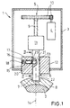
- 1 is an inventive device for electrical locking a steering shaft 2 of a motor vehicle steering device.
- the device 1 comprises a housing 3 and an electric motor 4 arranged in the housing 3 Downstream spindle drive 5 for moving a locking pin 6.
- the locking pin 6 engages in its locking position shown in Fig.1 in a groove-shaped Recess 7 of a locking ring 8 fastened to the steering spindle 2.
- the spindle drive 5 consists of a threaded spindle 9, which has a gear transmission 10 is driven by the electric motor 4, and one mounted in a guide Driver 11 with internal thread, which engages in the thread of the threaded spindle 9.
- the driver 11 does not have one on its side facing the locking pin 6 Shown shown on the locking pin 6 on its facing away from the steering shaft 2 Side with the driver 11 is connected interchangeably.
- the device 1 for guiding the front part 22 of the locking pin 6 a connectable to the housing 3 and the steering device of the vehicle Guide part 12, via which the device 1 according to the invention on the steering device is attachable.
- the guide part 12 contains for positive guidance of the Locking pin 6 has a guide recess 13 and is designed such that it is at a violent turning of the steering shaft 2 in the locked state of the locking pin 6 absorbs the forces acting on this part.
- first recess 15 In the guide part 12 is a transverse to the longitudinal axis 14 of the locking pin 6 extending first recess 15 is provided, which is closed on the outside and inside opens into the guide recess 13 via a first opening 23.
- first Recess 15 In the first Recess 15 is a securing bolt 17 acted upon by a compression spring 16 arranged longitudinally displaceable, the compression spring 16 on the of the guide recess 13 facing away from the outer wall 18.
- the first recess 15 In the area of the guide recess 13 is the first recess 15 by an inside of the housing 3 attached and in a second recess 19 of the guide part 12 perpendicular to the first Recess 15 displaceable, relatively flat strip-shaped closure element 20 closed (Fig. 2).
- the securing bolt is supported on this closure element 20 17 against the pressure of the prestressed compression spring 16 (Fig.1).
- the locking pin 6 there is a recess adapted to the locking pin 21, which is aligned with the first recess 15 of the guide part 12 and thus is opposite the first opening 23.
- the length is this recess 21 is chosen to be shorter than the length of the securing bolt 17.
- the invention is of course not based on the embodiment described above limited. So the dimensions of the locking bolt 17 and the recess 21 of the locking bolt 6 can be chosen such that the securing bolt 17 protrudes through the locking pin 6 after removal of the closure element 20 and on both sides of the locking pin 6 in corresponding recesses of the guide part 12 supports.
- the recess of the locking bolt not in the middle area, but arranged at the edge of the locking bolt and such is designed such that when the closure element is removed, the locking bolt is secured done by clamping.
- a corresponding embodiment is in Fig.3 reproduced, showing the case that the closure member 20 is removed has been.
- the securing bolt, again designated 17, has a circular shape Cross section on and has the designated 21 recess of the locking pin 6 a semicircular cross-sectional contour.
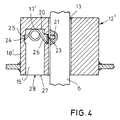
- the securing element does not necessarily have to be designed as a bolt, but this element can also be a leg spring, so that a separate spring is not required.
- a corresponding embodiment is there Fig. 4 again. 12 'denotes a guide part, which in turn is referred to as a guide recess 13 for guiding the locking pin 6 is provided.
- the guide part 12 ' has a first recess 15' which is parallel to the guide recess 13 extends and the facing the guide recess 13 Side has a first opening 23, which by a closure element 20th is closed.
- a prestressed leg spring 17 ' is arranged in the recess 15', which is with its first leg 24 in one in the outer wall 18 'of the guide member 12 'located recess 25 so that after assembly e.g. cannot slip when the vehicle moves within the first recess 15 '.
- With its second leg 26, the leg spring 17 ' is supported on the closure element 20 from.
- the first recess 15 ′ has a second opening 28 on its lower end face 27 through which the leg spring 17 'for assembly in a simple manner in its intended Position in the recess 15 'can be pushed.
- leg spring corresponds essentially those with spring-loaded safety bolts.
- the closure element 20 e.g. by violent destruction of the housing of the invention If the device is removed or moved, the leg spring relaxes 17 'and the second leg 26 is in the recess 21 of the locking pin 6th pivoted. A displacement of the locking pin 6 is then by the leg 26th blocked.
Abstract
Description
- 1
- Vorrichtung
- 2
- Lenkspindel
- 3
- Gehäuse
- 4
- Elektromotor
- 5
- Spindelantrieb
- 6
- Sperrbolzen
- 7
- nutenförmige Ausnehmung
- 8
- Schließring
- 9
- Gewindespindel
- 10
- Zahnradgetriebe
- 11
- Mitnehmer
- 12,12'
- Führungsteil
- 13
- Führungsausnehmung
- 14
- Längsachse
- 15,15'
- erste Ausnehmung (Führungsteil)
- 16
- Druckfeder
- 17
- Sicherungselement, Sicherungsbolzen
- 17'
- Sicherungselement, Schenkelfeder
- 18,18'
- Außenwand
- 19
- zweite Ausnehmung (Führungsteil)
- 20
- Verschlußelement
- 21
- Ausnehmung (Sperrbolzen)
- 22
- vordere Teil (Sperrbolzen)
- 23
- erste Öffnung
- 24
- erste Schenkel
- 25
- Vertiefung
- 26
- zweiter Schenkel
- 27
- Stirnseite
- 28
- zweite Öffnung
Claims (8)
- Vorrichtung zur Verriegelung der Lenkspindel (2) einer Lenkeinrichtung eines Fahrzeuges mit einem in einem Gehäuse (3) angeordneten und von einer Ent- in eine Verriegelungsstellung und umgekehrt verschiebbaren Sperrbolzen (6), mit den Merkmalen:a) die Vorrichtung (1) umfaßt auf ihrer der Lenkspindel (2) zugewandten Seite ein Führungsteil (12;12') mit einer an den Sperrbolzen (6) formschlüssig angepaßten Führungsausnehmung (13), in welcher der vordere Teil (22) des Sperrbolzens (6) verschiebbar gelagert ist;b) in dem Führungsteil (12;12') ist eine erste Ausnehmung (15;15') vorgesehen, die über eine erste Öffnung (23) in die Führungsausnehmung (13) mündet;c) in dem Sperrbolzen (6) befindet sich eine Ausnehmung (21), die in der Verriegelungsstellung des Sperrbolzens (6) der ersten Öffnung (23) der ersten Ausnehmung (15;15') des Führungsteiles (12;12') gegenüberliegt;d) in der ersten Ausnehmung (15;15') des Führungsteiles (12;12') ist ein federbeaufschlagtes Sicherungselement (17;17') angeordnet;e) die erste Öffnung (23) der ersten Ausnehmung (15;15') des Führungsteiles (12;12') ist durch ein an dem Gehäuse (3) innenseitig befestigtes und in einer zweiten Ausnehmung (19) senkrecht zur ersten Ausnehmung (15;15') verschiebbares Verschlußelement (20) verschlossen, an dem sich das diesem Element zugewandte Ende des federbeaufschlagten Sicherungselementes (17;17') abstützt, so daß in der Verriegelungsstellung des Sperrbolzens (6) bei Entfernen des Gehäusebereiches, an dem das Verschlußelement (20) befestigt ist, das Sicherungselement (17;17') durch die auf das Sicherungselement (17;17') ausgeübte Federkraft in die Ausnehmung (21) des Sperrbolzen (6) geschoben wird und den Sperrbolzen (6) in seiner Verriegelungsstellung sichert.
- Vorrichtung nach Anspruch 1, dadurch gekennzeichnet, daß die erste Ausnehmung (15) sich quer zur Längsachse (14) des Sperrbolzens (6) erstreckt und außenseitig verschlossen ist, und daß es sich bei dem Sicherungselement (17) um einen durch eine Druckfeder (16) beaufschlagten Sicherungsbolzen handelt, der in der ersten Ausnehmung (15) längsverschiebbar angeordnet ist, wobei sich die Druckfeder (16) an der der Führungsausnehmung (13) abgewandten Außenwand (18) der ersten Ausnehmung (15) abstützt.
- Vorrichtung nach Anspruch 1, dadurch gekennzeichnet, daß es sich bei dem in der ersten Ausnehmung (15') befindlichen Sicherungselement (17') um eine Schenkelfeder handelt, deren erster Schenkel (24) sich an der der Führungsausnehmung (13) abgewandten Außenwand (18') der ersten Ausnehmung (15') abstützt und deren zweiter Schenkel (26) sich an dem verschiebbaren Verschlußelement (20) abstützt.
- Vorrichtung nach Anspruch 3, dadurch gekennzeichnet, daß die erste Ausnehmung (15') sich mindestens teilweise parallel zur Führungsausnehmung (13) in dem Führungsteil (12') erstreckt und an einer der beiden Stirnseiten (27) des Führungsteiles (12') eine zweite Öffnung (28) aufweist, so daß die Schenkelfeder (17') durch die zweite Öffnung (28) in die erste Ausnehmung (15') einschiebbar ist.
- Vorrichtung nach Anspruch 3 oder 4, dadurch gekennzeichnet, daß der erste Schenkel (24) der Schenkelfeder (17') sich in einer in der Außenwand (18') des Führungsteiles (12') befindlichen Vertiefung (25) abstützt.
- Vorrichtung nach einem der Ansprüche 1 bis 5, dadurch gekennzeichnet, daß die Ausnehmung (21) des Sperrbolzens (6) an dessen Rand angeordnet und derart ausgestaltet ist, daß in der Verriegelungsstellung des Sperrbolzens (6) bei Entfernen des Verschlußelementes (20) eine Sicherung des Sperrbolzens (6) durch Klemmung erfolgt.
- Vorrichtung nach Anspruch 6, dadurch gekennzeichnet, daß bei Verwendung eines Sicherungsbolzens (17) als Sicherungselement dieser einen kreisförmigen Querschnitt aufweist und daß die Ausnehmung (21) des Sperrbolzens (6) eine halbkreisförmige Querschnittskontur besitzt .
- Vorrichtung nach einem der Ansprüche 1 bis 7, dadurch gekennzeichnet, daß das Verschlußelement (20) in dem Bereich des Gehäuses (3) befestigt ist, der dem Fahrzeuginnenraum zugewandt ist.
Priority Applications (1)
| Application Number | Priority Date | Filing Date | Title |
|---|---|---|---|
| EP20040011122 EP1447286B1 (de) | 2000-08-26 | 2001-08-08 | Vorrichtung zur Verriegelung der Lenkspindel eines Fahrzeuges |
Applications Claiming Priority (2)
| Application Number | Priority Date | Filing Date | Title |
|---|---|---|---|
| DE10041984 | 2000-08-26 | ||
| DE10041984A DE10041984B4 (de) | 2000-08-26 | 2000-08-26 | Vorrichtung zur Verriegelung der Lenkspindel eines Fahrzeuges |
Related Child Applications (1)
| Application Number | Title | Priority Date | Filing Date |
|---|---|---|---|
| EP20040011122 Division EP1447286B1 (de) | 2000-08-26 | 2001-08-08 | Vorrichtung zur Verriegelung der Lenkspindel eines Fahrzeuges |
Publications (3)
| Publication Number | Publication Date |
|---|---|
| EP1182104A2 true EP1182104A2 (de) | 2002-02-27 |
| EP1182104A3 EP1182104A3 (de) | 2004-01-28 |
| EP1182104B1 EP1182104B1 (de) | 2005-01-26 |
Family
ID=7653887
Family Applications (2)
| Application Number | Title | Priority Date | Filing Date |
|---|---|---|---|
| EP20040011122 Revoked EP1447286B1 (de) | 2000-08-26 | 2001-08-08 | Vorrichtung zur Verriegelung der Lenkspindel eines Fahrzeuges |
| EP20010202995 Expired - Lifetime EP1182104B1 (de) | 2000-08-26 | 2001-08-08 | Vorrichtung zur Verriegelung der Lenkspindel eines Fahrzeuges |
Family Applications Before (1)
| Application Number | Title | Priority Date | Filing Date |
|---|---|---|---|
| EP20040011122 Revoked EP1447286B1 (de) | 2000-08-26 | 2001-08-08 | Vorrichtung zur Verriegelung der Lenkspindel eines Fahrzeuges |
Country Status (6)
| Country | Link |
|---|---|
| US (1) | US6439011B1 (de) |
| EP (2) | EP1447286B1 (de) |
| JP (1) | JP5129421B2 (de) |
| AT (2) | ATE388867T1 (de) |
| DE (3) | DE10041984B4 (de) |
| ES (2) | ES2306938T3 (de) |
Cited By (10)
| Publication number | Priority date | Publication date | Assignee | Title |
|---|---|---|---|---|
| EP1688327A1 (de) * | 2005-02-07 | 2006-08-09 | Valeo Sicherheitssysteme GmbH | Sperrvorrichtung für eine Lenkspindel |
| EP2412587A1 (de) | 2010-07-29 | 2012-02-01 | Valeo Sicherheitssysteme | Verriegelungsvorrichtung einer Lenksäule eines Kraftfahrzeugs |
| CN101387169B (zh) * | 2007-07-20 | 2012-10-10 | 霍弗·霍斯贝克及弗斯特两合公司 | 具有制动件的锁装置 |
| WO2012137435A1 (en) * | 2011-04-04 | 2012-10-11 | Alpha Corporation | Steering lock device |
| CN104245440A (zh) * | 2012-04-27 | 2014-12-24 | 株式会社阿尔发 | 转向锁定装置 |
| US9457833B2 (en) | 2010-01-27 | 2016-10-04 | Strattec Security Corporation | Steering lock |
| EP3296164A1 (de) * | 2016-09-19 | 2018-03-21 | HUF Hülsbeck & Fürst GmbH & Co. KG | Gesicherte vorrichtung zum sperren eines funktionswesentlichen bauteils eines kraftfahrzeugs |
| EP3372458A1 (de) * | 2017-03-08 | 2018-09-12 | HUF Hülsbeck & Fürst GmbH & Co. KG | Sperrvorrichtung |
| DE102018202218A1 (de) * | 2018-02-13 | 2019-08-14 | Bayerische Motoren Werke Aktiengesellschaft | Getriebe für ein Motorrad, sowie Motorrad mit einem solchen Getriebe |
| DE102018203201A1 (de) * | 2018-03-02 | 2019-09-05 | Bayerische Motoren Werke Aktiengesellschaft | Antriebssperrbaugruppe sowie Kraftrad |
Families Citing this family (32)
| Publication number | Priority date | Publication date | Assignee | Title |
|---|---|---|---|---|
| DE10041984B4 (de) * | 2000-08-26 | 2006-02-23 | Valeo Sicherheitssysteme Gmbh | Vorrichtung zur Verriegelung der Lenkspindel eines Fahrzeuges |
| DE10103182B4 (de) * | 2001-01-24 | 2012-09-27 | Valeo Sicherheitssysteme Gmbh | Verriegelungsvorrichtung |
| JP3808789B2 (ja) * | 2002-03-22 | 2006-08-16 | 株式会社東海理化電機製作所 | 電動ステアリングロック装置 |
| JP3811416B2 (ja) * | 2002-03-22 | 2006-08-23 | 株式会社東海理化電機製作所 | 電動ステアリングロック装置 |
| WO2003099613A2 (en) * | 2002-05-23 | 2003-12-04 | Methode Electronics, Inc. | Steering lock device |
| DE10233511A1 (de) * | 2002-07-23 | 2004-04-22 | Huf Hülsbeck & Fürst Gmbh & Co. Kg | Schließsystem für Motorfahrzeuge |
| DE10247802B3 (de) | 2002-10-14 | 2004-02-05 | Huf Hülsbeck & Fürst Gmbh & Co. Kg | Vorrichtung zum Sperren der Lenkspindel eines Kraftfahrzeugs |
| DE10247803B3 (de) * | 2002-10-14 | 2004-01-29 | Huf Hülsbeck & Fürst Gmbh & Co. Kg | Vorrichtung zum Sperren der Lenkspindel eines Kraftfahrzeugs |
| JP4038132B2 (ja) * | 2003-01-31 | 2008-01-23 | 株式会社東海理化電機製作所 | 電動ステアリングロック装置 |
| GB2424045A (en) * | 2005-03-07 | 2006-09-13 | John Phillip Chevalier | Centrifugal clutch which is rotationally balanced when engaged |
| JP4980853B2 (ja) * | 2006-11-10 | 2012-07-18 | 株式会社アルファ | 電動ステアリングロック装置 |
| JP5147217B2 (ja) * | 2006-11-10 | 2013-02-20 | 株式会社アルファ | ステアリングロック装置 |
| DE102007018218A1 (de) * | 2007-04-16 | 2008-10-23 | Huf Hülsbeck & Fürst Gmbh & Co. Kg | Vorrichtung zur Ansteuerung eines Sperrgliedes |
| JP5073414B2 (ja) | 2007-08-23 | 2012-11-14 | 株式会社ユーシン | ステアリングロック装置 |
| JP5022880B2 (ja) * | 2007-11-30 | 2012-09-12 | 株式会社アルファ | ステアリングロック装置 |
| JP4881843B2 (ja) * | 2007-11-30 | 2012-02-22 | 株式会社アルファ | ステアリングロック装置 |
| DE102009033485A1 (de) * | 2009-07-15 | 2011-01-20 | Huf Hülsbeck & Fürst Gmbh & Co. Kg | Sperrvorrichtung zum Sperren eines funktionswesentlichen Bauteils eines Kraftfahrzeugs, insbesondere zur Sperrung einer Lenkspindel eines Kraftffahrzeugs |
| JP4952751B2 (ja) * | 2009-07-24 | 2012-06-13 | アイシン精機株式会社 | 車両用ドアロック装置 |
| DE102009034606B4 (de) * | 2009-07-24 | 2019-08-29 | Huf Hülsbeck & Fürst Gmbh & Co. Kg | Vorrichtung zum Sperren eines funktionswesentlichen Bauteils eines Kraftfahrzeugs |
| FR2952332B1 (fr) * | 2009-11-06 | 2013-11-29 | Valeo Securite Habitacle | Dispositif antivol pour colonne de direction de vehicule a super condamnation assuree par bascule intermediaire |
| JP5480615B2 (ja) * | 2009-12-24 | 2014-04-23 | 株式会社アルファ | ステアリングロック装置、およびステアリングロック装置の補助ロック部材組付構造 |
| US8424348B2 (en) * | 2010-01-27 | 2013-04-23 | Strattec Security Corporation | Steering lock |
| DE102010001911A1 (de) * | 2010-02-15 | 2011-08-18 | Robert Bosch GmbH, 70469 | Lenkvorrichtung für ein Fahrzeug |
| CN102834913B (zh) | 2010-07-26 | 2016-01-06 | 京瓷株式会社 | 静电吸盘 |
| PL2479073T3 (pl) * | 2011-01-21 | 2014-06-30 | Valeo Sicherheitssysteme Gmbh | Urządzenie układu kierowniczego, zapobiegające kradzieży, dla pojazdu samochodowego |
| DE102011011707A1 (de) * | 2011-02-18 | 2012-08-23 | Audi Ag | Als Diebstahlschutz wirkende Vorrichtung an einer Lenkradsperre |
| JP5352654B2 (ja) * | 2011-03-30 | 2013-11-27 | アイシン精機株式会社 | 車両用ドアロック装置 |
| JP5965202B2 (ja) * | 2012-04-27 | 2016-08-03 | 株式会社アルファ | ステアリングロック装置 |
| EP3053786B1 (de) * | 2013-10-03 | 2017-11-08 | Alpha Corporation | Lenkschlossvorrichtung |
| JP6258125B2 (ja) * | 2014-05-27 | 2018-01-10 | 株式会社アルファ | ステアリングロック装置 |
| DE102014112816A1 (de) | 2014-09-05 | 2016-03-10 | Huf Hülsbeck & Fürst Gmbh & Co. Kg | Lenkradverriegelung |
| US9889817B2 (en) * | 2015-10-27 | 2018-02-13 | Asahi Denso Co., Ltd. | Steering lock device |
Citations (1)
| Publication number | Priority date | Publication date | Assignee | Title |
|---|---|---|---|---|
| DE19713318C1 (de) | 1997-03-29 | 1998-08-06 | Valeo Gmbh & Co Schliessyst Kg | Lenkschloß-Gehäuse |
Family Cites Families (24)
| Publication number | Priority date | Publication date | Assignee | Title |
|---|---|---|---|---|
| US3914967A (en) * | 1974-06-20 | 1975-10-28 | Arman D | Steering-locking antitheft device for motor vehicles |
| IT1129385B (it) * | 1980-11-28 | 1986-06-04 | Arman Spa | Dispositivo antifurto bloccasterzo per autoveicoli |
| US4647229A (en) * | 1985-09-24 | 1987-03-03 | Lamcor, Inc. | Shaft restraining device |
| FR2594877B1 (fr) * | 1986-02-24 | 1991-06-21 | Fichet Bauche | Dispositif de verrouillage et deverrouillage d'un organe quelconque, tel que par exemple une barre comportant des penes |
| DE3611483C1 (en) * | 1986-04-05 | 1987-09-17 | Daimler Benz Ag | Steering lock for motor vehicles |
| GB2257767B (en) * | 1988-05-09 | 1993-05-05 | British Gas Plc | Pipelines. |
| IT223027Z2 (it) * | 1991-07-09 | 1995-05-25 | Trw Sipea Spa | Bloccasterzo antieffrazione per autoveicoli |
| JP2564909Y2 (ja) * | 1992-10-12 | 1998-03-11 | 株式会社東海理化電機製作所 | ステアリングロック装置 |
| US5595079A (en) * | 1994-04-06 | 1997-01-21 | Fort Lock Corporation | Motorcycle steering lock |
| DE4446613B4 (de) * | 1994-12-24 | 2004-04-29 | Marquardt Gmbh | Lenkradverriegelung an einem Kraftfahrzeug |
| FR2748054B1 (fr) * | 1996-04-29 | 1998-05-22 | Valeo Securite Habitacle | Dispositif de verrouillage motorise pour vehicule automobile comportant des moyens perfectionnes de limitation de la course du pene |
| US6125671A (en) * | 1996-11-13 | 2000-10-03 | Kabushiki Kaisha Tokai Rika Denki Seisakusho | Steering lock system |
| DE19704062C2 (de) * | 1997-02-04 | 1999-01-28 | Daimler Benz Ag | Elektromagnetisch betätigtes Schloß |
| DE19752519A1 (de) * | 1997-11-27 | 1999-06-10 | Bosch Gmbh Robert | Verriegelungseinrichtung für Lenkungen von Kraftfahrzeugen |
| FR2777522B1 (fr) * | 1998-04-21 | 2000-06-02 | Antivols Simplex Sa | Antivol de colonne de direction comportant une epingle elastique de blocage du pene |
| FR2777523B1 (fr) * | 1998-04-21 | 2000-06-02 | Antivols Simplex Sa | Antivol de colonne de direction comportant des moyens perfectionnes de blocage du pene |
| FR2783782B1 (fr) * | 1998-09-25 | 2000-10-20 | Antivols Simplex Sa | Antivol de colonne de direction comportant des moyens perfectionnes de blocage du pene |
| FR2784952B1 (fr) * | 1998-10-23 | 2000-12-08 | Antivols Simplex Sa | Antivol de colonne de direction comportant des moyens perfectionnes de blocage du pene |
| FR2788479B1 (fr) * | 1999-01-15 | 2001-04-06 | Valeo Securite Habitacle | Dispositif d'antivol comportant un interrupteur electrique pour la detection de l'introduction d'une clef |
| FR2788477B1 (fr) * | 1999-01-15 | 2001-02-16 | Valeo Securite Habitacle | Antivol de direction de vehicule automobile |
| FR2788478B1 (fr) * | 1999-01-15 | 2001-04-06 | Valeo Securite Habitacle | Antivol de direction de vehicule automobile |
| DE19906267C2 (de) * | 1999-02-15 | 2001-03-15 | Valeo Deutschland Gmbh & Co | Vorrichtung zur elektrischen Verriegelung der Lenkspindel einer Kraftfahrzeug-Lenkeinrichtung |
| FR2799426B1 (fr) * | 1999-09-17 | 2001-12-07 | Valeo Securite Habitacle | Antivol de direction de vehicule automobile |
| DE10041984B4 (de) * | 2000-08-26 | 2006-02-23 | Valeo Sicherheitssysteme Gmbh | Vorrichtung zur Verriegelung der Lenkspindel eines Fahrzeuges |
-
2000
- 2000-08-26 DE DE10041984A patent/DE10041984B4/de not_active Revoked
-
2001
- 2001-08-08 EP EP20040011122 patent/EP1447286B1/de not_active Revoked
- 2001-08-08 EP EP20010202995 patent/EP1182104B1/de not_active Expired - Lifetime
- 2001-08-08 ES ES04011122T patent/ES2306938T3/es not_active Expired - Lifetime
- 2001-08-08 AT AT04011122T patent/ATE388867T1/de not_active IP Right Cessation
- 2001-08-08 DE DE50113739T patent/DE50113739D1/de not_active Expired - Lifetime
- 2001-08-08 AT AT01202995T patent/ATE287810T1/de not_active IP Right Cessation
- 2001-08-08 DE DE50105177T patent/DE50105177D1/de not_active Expired - Lifetime
- 2001-08-08 ES ES01202995T patent/ES2236126T3/es not_active Expired - Lifetime
- 2001-08-27 JP JP2001256474A patent/JP5129421B2/ja not_active Expired - Fee Related
- 2001-08-27 US US09/938,673 patent/US6439011B1/en not_active Expired - Lifetime
Patent Citations (1)
| Publication number | Priority date | Publication date | Assignee | Title |
|---|---|---|---|---|
| DE19713318C1 (de) | 1997-03-29 | 1998-08-06 | Valeo Gmbh & Co Schliessyst Kg | Lenkschloß-Gehäuse |
Cited By (18)
| Publication number | Priority date | Publication date | Assignee | Title |
|---|---|---|---|---|
| EP1688327A1 (de) * | 2005-02-07 | 2006-08-09 | Valeo Sicherheitssysteme GmbH | Sperrvorrichtung für eine Lenkspindel |
| US8474291B2 (en) | 2007-07-20 | 2013-07-02 | Huf Hulsbeck & Furst Gmbh Co. Kg | Locking device with arresting part |
| CN101387169B (zh) * | 2007-07-20 | 2012-10-10 | 霍弗·霍斯贝克及弗斯特两合公司 | 具有制动件的锁装置 |
| KR101437178B1 (ko) * | 2007-07-20 | 2014-09-03 | 후프 휠스벡 운트 퓌르스트 게엠베하 운트 콤파니 카게 | 억류부를 구비한 쇄정 장치 |
| US9457833B2 (en) | 2010-01-27 | 2016-10-04 | Strattec Security Corporation | Steering lock |
| EP2412587A1 (de) | 2010-07-29 | 2012-02-01 | Valeo Sicherheitssysteme | Verriegelungsvorrichtung einer Lenksäule eines Kraftfahrzeugs |
| CN103459209B (zh) * | 2011-04-04 | 2016-06-22 | 株式会社阿尔发 | 转向锁定装置 |
| US8925415B2 (en) | 2011-04-04 | 2015-01-06 | Alpha Corporation | Steering lock device |
| RU2537932C1 (ru) * | 2011-04-04 | 2015-01-10 | Альфа Корпорейшн | Устройство для блокировки рулевой колонки |
| CN103459209A (zh) * | 2011-04-04 | 2013-12-18 | 株式会社阿尔发 | 转向锁定装置 |
| WO2012137435A1 (en) * | 2011-04-04 | 2012-10-11 | Alpha Corporation | Steering lock device |
| CN104245440A (zh) * | 2012-04-27 | 2014-12-24 | 株式会社阿尔发 | 转向锁定装置 |
| CN104245440B (zh) * | 2012-04-27 | 2016-05-04 | 株式会社阿尔发 | 转向锁定装置 |
| EP3296164A1 (de) * | 2016-09-19 | 2018-03-21 | HUF Hülsbeck & Fürst GmbH & Co. KG | Gesicherte vorrichtung zum sperren eines funktionswesentlichen bauteils eines kraftfahrzeugs |
| EP3372458A1 (de) * | 2017-03-08 | 2018-09-12 | HUF Hülsbeck & Fürst GmbH & Co. KG | Sperrvorrichtung |
| DE102018202218A1 (de) * | 2018-02-13 | 2019-08-14 | Bayerische Motoren Werke Aktiengesellschaft | Getriebe für ein Motorrad, sowie Motorrad mit einem solchen Getriebe |
| US11840299B2 (en) | 2018-02-13 | 2023-12-12 | Bayerische Motoren Werke Aktiengesellschaft | Transmission for a motorcycle, and motorcycle comprising such a transmission |
| DE102018203201A1 (de) * | 2018-03-02 | 2019-09-05 | Bayerische Motoren Werke Aktiengesellschaft | Antriebssperrbaugruppe sowie Kraftrad |
Also Published As
| Publication number | Publication date |
|---|---|
| JP5129421B2 (ja) | 2013-01-30 |
| ATE388867T1 (de) | 2008-03-15 |
| DE50105177D1 (de) | 2005-03-03 |
| EP1182104B1 (de) | 2005-01-26 |
| ATE287810T1 (de) | 2005-02-15 |
| JP2002120695A (ja) | 2002-04-23 |
| EP1447286A1 (de) | 2004-08-18 |
| EP1447286B1 (de) | 2008-03-12 |
| ES2306938T3 (es) | 2008-11-16 |
| US6439011B1 (en) | 2002-08-27 |
| EP1182104A3 (de) | 2004-01-28 |
| US20020023468A1 (en) | 2002-02-28 |
| DE10041984A1 (de) | 2002-04-18 |
| ES2236126T3 (es) | 2005-07-16 |
| DE50113739D1 (de) | 2008-04-24 |
| DE10041984B4 (de) | 2006-02-23 |
Similar Documents
| Publication | Publication Date | Title |
|---|---|---|
| EP1182104B1 (de) | Vorrichtung zur Verriegelung der Lenkspindel eines Fahrzeuges | |
| DE69824071T2 (de) | Lenksäulenverriegelung | |
| DE10156335C2 (de) | Vorrichtung zum Sperren der Lenkspindel eines Kraftfahrzeugs | |
| DE69922373T2 (de) | Verschlussvorrichtung und haubenschloss für ein fahrzeug mit einer derartigen verschlussvorrichtung | |
| EP1427905B1 (de) | Griffbeschlag | |
| DE10022373B4 (de) | Verriegelungs- und Betätigungseinheit für seitliche Auslegerverriegelung | |
| DE3223778C2 (de) | ||
| DE69908238T2 (de) | Diebstahlsschutzvorrichtung für eine Steuersäule mit Mitteln zur Bolzenverriegelung | |
| DE202014103252U1 (de) | Kraftfahrzeugschloss | |
| DE602004003658T2 (de) | Schlüssel zur Betätigung eines Schlosses | |
| DE10301998B4 (de) | Schließhilfe zum Verschließen einer mit einem Türschloß versehenen Fahrzeugtür | |
| DE69916122T2 (de) | Zylinderschloss | |
| EP0036141B1 (de) | Steckschlüsselbetätigbare Arretierungsvorrichtung | |
| CH709435B1 (de) | Einsteckschloss für einen Flügel einer Tür oder eines Fensters. | |
| EP1835095A1 (de) | Schlüssel für einen Schließzylinder | |
| CH659505A5 (en) | Edge mechanism for a wing of a window or a door | |
| DE10042282B4 (de) | Türverkrallung | |
| DE102004007083B3 (de) | Betätigungsvorrichtung für Türen oder Klappen | |
| DE2252473A1 (de) | Lenk- und zuendschloss, insbesondere fuer kraftfahrzeuge | |
| DE10317448A1 (de) | Kupplungseinrichtung an Doppelschließzylinder | |
| EP0156793B1 (de) | Einrichtung zur Befestigung einer Türdrückereinheit in einem Türschloss | |
| DE3214839C2 (de) | Kraftfahrzeug-Lenkschloß | |
| EP0949128A2 (de) | Sicherungsvorrichtung für ein Lenkradschloss | |
| EP3800315B1 (de) | Antriebsmodul zum verlagern eines verschlusselements relativ zu einem rahmen in einer gebäudeöffnung | |
| EP3474303A1 (de) | Betätiger |
Legal Events
| Date | Code | Title | Description |
|---|---|---|---|
| PUAI | Public reference made under article 153(3) epc to a published international application that has entered the european phase |
Free format text: ORIGINAL CODE: 0009012 |
|
| AK | Designated contracting states |
Kind code of ref document: A2 Designated state(s): AT BE CH CY DE DK ES FI FR GB GR IE IT LI LU MC NL PT SE TR |
|
| AX | Request for extension of the european patent |
Free format text: AL;LT;LV;MK;RO;SI |
|
| PUAL | Search report despatched |
Free format text: ORIGINAL CODE: 0009013 |
|
| AK | Designated contracting states |
Kind code of ref document: A3 Designated state(s): AT BE CH CY DE DK ES FI FR GB GR IE IT LI LU MC NL PT SE TR |
|
| AX | Request for extension of the european patent |
Extension state: AL LT LV MK RO SI |
|
| RAP1 | Party data changed (applicant data changed or rights of an application transferred) |
Owner name: VALEO SICHERHEITSSYSTEME GMBH |
|
| 17P | Request for examination filed |
Effective date: 20040512 |
|
| GRAP | Despatch of communication of intention to grant a patent |
Free format text: ORIGINAL CODE: EPIDOSNIGR1 |
|
| AKX | Designation fees paid |
Designated state(s): AT BE CH CY DE DK ES FI FR GB GR IE IT LI LU MC NL PT SE TR |
|
| GRAS | Grant fee paid |
Free format text: ORIGINAL CODE: EPIDOSNIGR3 |
|
| GRAA | (expected) grant |
Free format text: ORIGINAL CODE: 0009210 |
|
| AK | Designated contracting states |
Kind code of ref document: B1 Designated state(s): AT BE CH CY DE DK ES FI FR GB GR IE IT LI LU MC NL PT SE TR |
|
| PG25 | Lapsed in a contracting state [announced via postgrant information from national office to epo] |
Ref country code: IE Free format text: LAPSE BECAUSE OF FAILURE TO SUBMIT A TRANSLATION OF THE DESCRIPTION OR TO PAY THE FEE WITHIN THE PRESCRIBED TIME-LIMIT Effective date: 20050126 Ref country code: TR Free format text: LAPSE BECAUSE OF FAILURE TO SUBMIT A TRANSLATION OF THE DESCRIPTION OR TO PAY THE FEE WITHIN THE PRESCRIBED TIME-LIMIT Effective date: 20050126 Ref country code: FI Free format text: LAPSE BECAUSE OF FAILURE TO SUBMIT A TRANSLATION OF THE DESCRIPTION OR TO PAY THE FEE WITHIN THE PRESCRIBED TIME-LIMIT Effective date: 20050126 Ref country code: NL Free format text: LAPSE BECAUSE OF FAILURE TO SUBMIT A TRANSLATION OF THE DESCRIPTION OR TO PAY THE FEE WITHIN THE PRESCRIBED TIME-LIMIT Effective date: 20050126 |
|
| REG | Reference to a national code |
Ref country code: GB Ref legal event code: FG4D Free format text: NOT ENGLISH Ref country code: IE Ref legal event code: FG4D Free format text: GERMAN |
|
| REG | Reference to a national code |
Ref country code: CH Ref legal event code: EP |
|
| REG | Reference to a national code |
Ref country code: SE Ref legal event code: TRGR |
|
| GBT | Gb: translation of ep patent filed (gb section 77(6)(a)/1977) |
Effective date: 20050202 |
|
| REF | Corresponds to: |
Ref document number: 50105177 Country of ref document: DE Date of ref document: 20050303 Kind code of ref document: P |
|
| PG25 | Lapsed in a contracting state [announced via postgrant information from national office to epo] |
Ref country code: DK Free format text: LAPSE BECAUSE OF FAILURE TO SUBMIT A TRANSLATION OF THE DESCRIPTION OR TO PAY THE FEE WITHIN THE PRESCRIBED TIME-LIMIT Effective date: 20050426 Ref country code: GR Free format text: LAPSE BECAUSE OF FAILURE TO SUBMIT A TRANSLATION OF THE DESCRIPTION OR TO PAY THE FEE WITHIN THE PRESCRIBED TIME-LIMIT Effective date: 20050426 |
|
| NLV1 | Nl: lapsed or annulled due to failure to fulfill the requirements of art. 29p and 29m of the patents act | ||
| REG | Reference to a national code |
Ref country code: ES Ref legal event code: FG2A Ref document number: 2236126 Country of ref document: ES Kind code of ref document: T3 |
|
| PG25 | Lapsed in a contracting state [announced via postgrant information from national office to epo] |
Ref country code: LU Free format text: LAPSE BECAUSE OF NON-PAYMENT OF DUE FEES Effective date: 20050808 Ref country code: CY Free format text: LAPSE BECAUSE OF FAILURE TO SUBMIT A TRANSLATION OF THE DESCRIPTION OR TO PAY THE FEE WITHIN THE PRESCRIBED TIME-LIMIT Effective date: 20050808 Ref country code: AT Free format text: LAPSE BECAUSE OF NON-PAYMENT OF DUE FEES Effective date: 20050808 |
|
| REG | Reference to a national code |
Ref country code: IE Ref legal event code: FD4D |
|
| PG25 | Lapsed in a contracting state [announced via postgrant information from national office to epo] |
Ref country code: BE Free format text: LAPSE BECAUSE OF NON-PAYMENT OF DUE FEES Effective date: 20050831 Ref country code: LI Free format text: LAPSE BECAUSE OF NON-PAYMENT OF DUE FEES Effective date: 20050831 Ref country code: CH Free format text: LAPSE BECAUSE OF NON-PAYMENT OF DUE FEES Effective date: 20050831 Ref country code: MC Free format text: LAPSE BECAUSE OF NON-PAYMENT OF DUE FEES Effective date: 20050831 |
|
| ET | Fr: translation filed | ||
| PLBI | Opposition filed |
Free format text: ORIGINAL CODE: 0009260 |
|
| PLAX | Notice of opposition and request to file observation + time limit sent |
Free format text: ORIGINAL CODE: EPIDOSNOBS2 |
|
| 26 | Opposition filed |
Opponent name: HUF HUELSBECK & FUERST GMBH. & CO. KG. Effective date: 20051022 |
|
| PLAF | Information modified related to communication of a notice of opposition and request to file observations + time limit |
Free format text: ORIGINAL CODE: EPIDOSCOBS2 |
|
| REG | Reference to a national code |
Ref country code: CH Ref legal event code: PL |
|
| PLBB | Reply of patent proprietor to notice(s) of opposition received |
Free format text: ORIGINAL CODE: EPIDOSNOBS3 |
|
| PLCK | Communication despatched that opposition was rejected |
Free format text: ORIGINAL CODE: EPIDOSNREJ1 |
|
| PLBN | Opposition rejected |
Free format text: ORIGINAL CODE: 0009273 |
|
| STAA | Information on the status of an ep patent application or granted ep patent |
Free format text: STATUS: OPPOSITION REJECTED |
|
| 27O | Opposition rejected |
Effective date: 20070327 |
|
| BERE | Be: lapsed |
Owner name: VALEO SICHERHEITSSYSTEME G.M.B.H. Effective date: 20050831 |
|
| PG25 | Lapsed in a contracting state [announced via postgrant information from national office to epo] |
Ref country code: PT Free format text: LAPSE BECAUSE OF NON-PAYMENT OF DUE FEES Effective date: 20050626 |
|
| PGFP | Annual fee paid to national office [announced via postgrant information from national office to epo] |
Ref country code: SE Payment date: 20140813 Year of fee payment: 14 Ref country code: ES Payment date: 20140820 Year of fee payment: 14 |
|
| REG | Reference to a national code |
Ref country code: DE Ref legal event code: R082 Ref document number: 50105177 Country of ref document: DE Representative=s name: PODSZUS, BURGHART, DIPL.-PHYS. DIPL.-WIRTSCH.-, DE |
|
| PGFP | Annual fee paid to national office [announced via postgrant information from national office to epo] |
Ref country code: IT Payment date: 20140808 Year of fee payment: 14 |
|
| REG | Reference to a national code |
Ref country code: DE Ref legal event code: R082 Ref document number: 50105177 Country of ref document: DE Representative=s name: PODSZUS, BURGHART, DIPL.-PHYS. DIPL.-WIRTSCH.-, DE Effective date: 20141219 Ref country code: DE Ref legal event code: R081 Ref document number: 50105177 Country of ref document: DE Owner name: U-SHIN DEUTSCHLAND ZUGANGSSYSTEME GMBH, DE Free format text: FORMER OWNER: VALEO SICHERHEITSSYSTEME GMBH, 85253 ERDWEG, DE Effective date: 20141219 |
|
| REG | Reference to a national code |
Ref country code: DE Ref legal event code: R082 Ref document number: 50105177 Country of ref document: DE |
|
| REG | Reference to a national code |
Ref country code: ES Ref legal event code: PC2A Owner name: U-SHIN DEUTSCHLAND ZUGANGSSYSTEME GMBH Effective date: 20150618 |
|
| REG | Reference to a national code |
Ref country code: SE Ref legal event code: EUG |
|
| PG25 | Lapsed in a contracting state [announced via postgrant information from national office to epo] |
Ref country code: IT Free format text: LAPSE BECAUSE OF NON-PAYMENT OF DUE FEES Effective date: 20150808 |
|
| PG25 | Lapsed in a contracting state [announced via postgrant information from national office to epo] |
Ref country code: SE Free format text: LAPSE BECAUSE OF NON-PAYMENT OF DUE FEES Effective date: 20150809 |
|
| REG | Reference to a national code |
Ref country code: FR Ref legal event code: PLFP Year of fee payment: 16 |
|
| REG | Reference to a national code |
Ref country code: ES Ref legal event code: FD2A Effective date: 20160926 |
|
| PG25 | Lapsed in a contracting state [announced via postgrant information from national office to epo] |
Ref country code: ES Free format text: LAPSE BECAUSE OF NON-PAYMENT OF DUE FEES Effective date: 20150809 |
|
| REG | Reference to a national code |
Ref country code: FR Ref legal event code: PLFP Year of fee payment: 17 |
|
| REG | Reference to a national code |
Ref country code: FR Ref legal event code: PLFP Year of fee payment: 18 |
|
| PGFP | Annual fee paid to national office [announced via postgrant information from national office to epo] |
Ref country code: FR Payment date: 20180830 Year of fee payment: 18 |
|
| PGFP | Annual fee paid to national office [announced via postgrant information from national office to epo] |
Ref country code: GB Payment date: 20180821 Year of fee payment: 18 |
|
| GBPC | Gb: european patent ceased through non-payment of renewal fee |
Effective date: 20190808 |
|
| PG25 | Lapsed in a contracting state [announced via postgrant information from national office to epo] |
Ref country code: FR Free format text: LAPSE BECAUSE OF NON-PAYMENT OF DUE FEES Effective date: 20190831 |
|
| PG25 | Lapsed in a contracting state [announced via postgrant information from national office to epo] |
Ref country code: GB Free format text: LAPSE BECAUSE OF NON-PAYMENT OF DUE FEES Effective date: 20190808 |
|
| PGFP | Annual fee paid to national office [announced via postgrant information from national office to epo] |
Ref country code: DE Payment date: 20200806 Year of fee payment: 20 |
|
| REG | Reference to a national code |
Ref country code: DE Ref legal event code: R071 Ref document number: 50105177 Country of ref document: DE |