EP1184803A2 - Electro-optical scanning assembly with one-piece oscillatable focussing/scan element - Google Patents
Electro-optical scanning assembly with one-piece oscillatable focussing/scan element Download PDFInfo
- Publication number
- EP1184803A2 EP1184803A2 EP01120999A EP01120999A EP1184803A2 EP 1184803 A2 EP1184803 A2 EP 1184803A2 EP 01120999 A EP01120999 A EP 01120999A EP 01120999 A EP01120999 A EP 01120999A EP 1184803 A2 EP1184803 A2 EP 1184803A2
- Authority
- EP
- European Patent Office
- Prior art keywords
- optical component
- support
- light beam
- focusing
- light
- Prior art date
- Legal status (The legal status is an assumption and is not a legal conclusion. Google has not performed a legal analysis and makes no representation as to the accuracy of the status listed.)
- Granted
Links
Images

Classifications
-
- G—PHYSICS
- G06—COMPUTING; CALCULATING OR COUNTING
- G06K—GRAPHICAL DATA READING; PRESENTATION OF DATA; RECORD CARRIERS; HANDLING RECORD CARRIERS
- G06K7/00—Methods or arrangements for sensing record carriers, e.g. for reading patterns
- G06K7/10—Methods or arrangements for sensing record carriers, e.g. for reading patterns by electromagnetic radiation, e.g. optical sensing; by corpuscular radiation
- G06K7/10544—Methods or arrangements for sensing record carriers, e.g. for reading patterns by electromagnetic radiation, e.g. optical sensing; by corpuscular radiation by scanning of the records by radiation in the optical part of the electromagnetic spectrum
- G06K7/10554—Moving beam scanning
- G06K7/10564—Light sources
- G06K7/10584—Source control
-
- G—PHYSICS
- G06—COMPUTING; CALCULATING OR COUNTING
- G06K—GRAPHICAL DATA READING; PRESENTATION OF DATA; RECORD CARRIERS; HANDLING RECORD CARRIERS
- G06K7/00—Methods or arrangements for sensing record carriers, e.g. for reading patterns
- G06K7/10—Methods or arrangements for sensing record carriers, e.g. for reading patterns by electromagnetic radiation, e.g. optical sensing; by corpuscular radiation
- G06K7/10544—Methods or arrangements for sensing record carriers, e.g. for reading patterns by electromagnetic radiation, e.g. optical sensing; by corpuscular radiation by scanning of the records by radiation in the optical part of the electromagnetic spectrum
- G06K7/10554—Moving beam scanning
- G06K7/10594—Beam path
- G06K7/10603—Basic scanning using moving elements
- G06K7/10633—Basic scanning using moving elements by oscillation
- G06K7/10643—Activating means
- G06K7/10653—Activating means using flexible or piezoelectric means
-
- G—PHYSICS
- G06—COMPUTING; CALCULATING OR COUNTING
- G06K—GRAPHICAL DATA READING; PRESENTATION OF DATA; RECORD CARRIERS; HANDLING RECORD CARRIERS
- G06K7/00—Methods or arrangements for sensing record carriers, e.g. for reading patterns
- G06K7/10—Methods or arrangements for sensing record carriers, e.g. for reading patterns by electromagnetic radiation, e.g. optical sensing; by corpuscular radiation
- G06K7/10544—Methods or arrangements for sensing record carriers, e.g. for reading patterns by electromagnetic radiation, e.g. optical sensing; by corpuscular radiation by scanning of the records by radiation in the optical part of the electromagnetic spectrum
- G06K7/10554—Moving beam scanning
- G06K7/10594—Beam path
- G06K7/10603—Basic scanning using moving elements
- G06K7/10673—Parallel lines
-
- G—PHYSICS
- G06—COMPUTING; CALCULATING OR COUNTING
- G06K—GRAPHICAL DATA READING; PRESENTATION OF DATA; RECORD CARRIERS; HANDLING RECORD CARRIERS
- G06K7/00—Methods or arrangements for sensing record carriers, e.g. for reading patterns
- G06K7/10—Methods or arrangements for sensing record carriers, e.g. for reading patterns by electromagnetic radiation, e.g. optical sensing; by corpuscular radiation
- G06K7/10544—Methods or arrangements for sensing record carriers, e.g. for reading patterns by electromagnetic radiation, e.g. optical sensing; by corpuscular radiation by scanning of the records by radiation in the optical part of the electromagnetic spectrum
- G06K7/10554—Moving beam scanning
- G06K7/10594—Beam path
- G06K7/10683—Arrangement of fixed elements
- G06K7/10693—Arrangement of fixed elements for omnidirectional scanning
-
- G—PHYSICS
- G06—COMPUTING; CALCULATING OR COUNTING
- G06K—GRAPHICAL DATA READING; PRESENTATION OF DATA; RECORD CARRIERS; HANDLING RECORD CARRIERS
- G06K7/00—Methods or arrangements for sensing record carriers, e.g. for reading patterns
- G06K7/10—Methods or arrangements for sensing record carriers, e.g. for reading patterns by electromagnetic radiation, e.g. optical sensing; by corpuscular radiation
- G06K7/10544—Methods or arrangements for sensing record carriers, e.g. for reading patterns by electromagnetic radiation, e.g. optical sensing; by corpuscular radiation by scanning of the records by radiation in the optical part of the electromagnetic spectrum
- G06K7/10792—Special measures in relation to the object to be scanned
- G06K7/10801—Multidistance reading
- G06K7/10811—Focalisation
-
- G—PHYSICS
- G06—COMPUTING; CALCULATING OR COUNTING
- G06K—GRAPHICAL DATA READING; PRESENTATION OF DATA; RECORD CARRIERS; HANDLING RECORD CARRIERS
- G06K7/00—Methods or arrangements for sensing record carriers, e.g. for reading patterns
- G06K7/10—Methods or arrangements for sensing record carriers, e.g. for reading patterns by electromagnetic radiation, e.g. optical sensing; by corpuscular radiation
- G06K7/10544—Methods or arrangements for sensing record carriers, e.g. for reading patterns by electromagnetic radiation, e.g. optical sensing; by corpuscular radiation by scanning of the records by radiation in the optical part of the electromagnetic spectrum
- G06K7/10821—Methods or arrangements for sensing record carriers, e.g. for reading patterns by electromagnetic radiation, e.g. optical sensing; by corpuscular radiation by scanning of the records by radiation in the optical part of the electromagnetic spectrum further details of bar or optical code scanning devices
- G06K7/10851—Circuits for pulse shaping, amplifying, eliminating noise signals, checking the function of the sensing device
-
- G—PHYSICS
- G06—COMPUTING; CALCULATING OR COUNTING
- G06K—GRAPHICAL DATA READING; PRESENTATION OF DATA; RECORD CARRIERS; HANDLING RECORD CARRIERS
- G06K7/00—Methods or arrangements for sensing record carriers, e.g. for reading patterns
- G06K7/10—Methods or arrangements for sensing record carriers, e.g. for reading patterns by electromagnetic radiation, e.g. optical sensing; by corpuscular radiation
- G06K7/10544—Methods or arrangements for sensing record carriers, e.g. for reading patterns by electromagnetic radiation, e.g. optical sensing; by corpuscular radiation by scanning of the records by radiation in the optical part of the electromagnetic spectrum
- G06K7/10821—Methods or arrangements for sensing record carriers, e.g. for reading patterns by electromagnetic radiation, e.g. optical sensing; by corpuscular radiation by scanning of the records by radiation in the optical part of the electromagnetic spectrum further details of bar or optical code scanning devices
- G06K7/10861—Methods or arrangements for sensing record carriers, e.g. for reading patterns by electromagnetic radiation, e.g. optical sensing; by corpuscular radiation by scanning of the records by radiation in the optical part of the electromagnetic spectrum further details of bar or optical code scanning devices sensing of data fields affixed to objects or articles, e.g. coded labels
- G06K7/10871—Methods or arrangements for sensing record carriers, e.g. for reading patterns by electromagnetic radiation, e.g. optical sensing; by corpuscular radiation by scanning of the records by radiation in the optical part of the electromagnetic spectrum further details of bar or optical code scanning devices sensing of data fields affixed to objects or articles, e.g. coded labels randomly oriented data-fields, code-marks therefore, e.g. concentric circles-code
-
- G—PHYSICS
- G06—COMPUTING; CALCULATING OR COUNTING
- G06K—GRAPHICAL DATA READING; PRESENTATION OF DATA; RECORD CARRIERS; HANDLING RECORD CARRIERS
- G06K7/00—Methods or arrangements for sensing record carriers, e.g. for reading patterns
- G06K7/10—Methods or arrangements for sensing record carriers, e.g. for reading patterns by electromagnetic radiation, e.g. optical sensing; by corpuscular radiation
- G06K7/10544—Methods or arrangements for sensing record carriers, e.g. for reading patterns by electromagnetic radiation, e.g. optical sensing; by corpuscular radiation by scanning of the records by radiation in the optical part of the electromagnetic spectrum
- G06K7/10821—Methods or arrangements for sensing record carriers, e.g. for reading patterns by electromagnetic radiation, e.g. optical sensing; by corpuscular radiation by scanning of the records by radiation in the optical part of the electromagnetic spectrum further details of bar or optical code scanning devices
- G06K7/10881—Methods or arrangements for sensing record carriers, e.g. for reading patterns by electromagnetic radiation, e.g. optical sensing; by corpuscular radiation by scanning of the records by radiation in the optical part of the electromagnetic spectrum further details of bar or optical code scanning devices constructional details of hand-held scanners
- G06K7/10891—Methods or arrangements for sensing record carriers, e.g. for reading patterns by electromagnetic radiation, e.g. optical sensing; by corpuscular radiation by scanning of the records by radiation in the optical part of the electromagnetic spectrum further details of bar or optical code scanning devices constructional details of hand-held scanners the scanner to be worn on a finger or on a wrist
-
- G—PHYSICS
- G06—COMPUTING; CALCULATING OR COUNTING
- G06K—GRAPHICAL DATA READING; PRESENTATION OF DATA; RECORD CARRIERS; HANDLING RECORD CARRIERS
- G06K7/00—Methods or arrangements for sensing record carriers, e.g. for reading patterns
- G06K7/10—Methods or arrangements for sensing record carriers, e.g. for reading patterns by electromagnetic radiation, e.g. optical sensing; by corpuscular radiation
- G06K7/10544—Methods or arrangements for sensing record carriers, e.g. for reading patterns by electromagnetic radiation, e.g. optical sensing; by corpuscular radiation by scanning of the records by radiation in the optical part of the electromagnetic spectrum
- G06K7/10821—Methods or arrangements for sensing record carriers, e.g. for reading patterns by electromagnetic radiation, e.g. optical sensing; by corpuscular radiation by scanning of the records by radiation in the optical part of the electromagnetic spectrum further details of bar or optical code scanning devices
- G06K7/10881—Methods or arrangements for sensing record carriers, e.g. for reading patterns by electromagnetic radiation, e.g. optical sensing; by corpuscular radiation by scanning of the records by radiation in the optical part of the electromagnetic spectrum further details of bar or optical code scanning devices constructional details of hand-held scanners
- G06K7/109—Methods or arrangements for sensing record carriers, e.g. for reading patterns by electromagnetic radiation, e.g. optical sensing; by corpuscular radiation by scanning of the records by radiation in the optical part of the electromagnetic spectrum further details of bar or optical code scanning devices constructional details of hand-held scanners adaptations to make the hand-held scanner useable as a fixed scanner
-
- G—PHYSICS
- G06—COMPUTING; CALCULATING OR COUNTING
- G06K—GRAPHICAL DATA READING; PRESENTATION OF DATA; RECORD CARRIERS; HANDLING RECORD CARRIERS
- G06K7/00—Methods or arrangements for sensing record carriers, e.g. for reading patterns
- G06K7/10—Methods or arrangements for sensing record carriers, e.g. for reading patterns by electromagnetic radiation, e.g. optical sensing; by corpuscular radiation
- G06K7/10544—Methods or arrangements for sensing record carriers, e.g. for reading patterns by electromagnetic radiation, e.g. optical sensing; by corpuscular radiation by scanning of the records by radiation in the optical part of the electromagnetic spectrum
- G06K7/10821—Methods or arrangements for sensing record carriers, e.g. for reading patterns by electromagnetic radiation, e.g. optical sensing; by corpuscular radiation by scanning of the records by radiation in the optical part of the electromagnetic spectrum further details of bar or optical code scanning devices
- G06K7/1098—Methods or arrangements for sensing record carriers, e.g. for reading patterns by electromagnetic radiation, e.g. optical sensing; by corpuscular radiation by scanning of the records by radiation in the optical part of the electromagnetic spectrum further details of bar or optical code scanning devices the scanning arrangement having a modular construction
-
- G—PHYSICS
- G06—COMPUTING; CALCULATING OR COUNTING
- G06K—GRAPHICAL DATA READING; PRESENTATION OF DATA; RECORD CARRIERS; HANDLING RECORD CARRIERS
- G06K7/00—Methods or arrangements for sensing record carriers, e.g. for reading patterns
- G06K7/10—Methods or arrangements for sensing record carriers, e.g. for reading patterns by electromagnetic radiation, e.g. optical sensing; by corpuscular radiation
- G06K7/14—Methods or arrangements for sensing record carriers, e.g. for reading patterns by electromagnetic radiation, e.g. optical sensing; by corpuscular radiation using light without selection of wavelength, e.g. sensing reflected white light
- G06K7/1404—Methods for optical code recognition
- G06K7/146—Methods for optical code recognition the method including quality enhancement steps
- G06K7/1478—Methods for optical code recognition the method including quality enhancement steps adapting the threshold for pixels in a CMOS or CCD pixel sensor for black and white recognition
-
- G—PHYSICS
- G06—COMPUTING; CALCULATING OR COUNTING
- G06K—GRAPHICAL DATA READING; PRESENTATION OF DATA; RECORD CARRIERS; HANDLING RECORD CARRIERS
- G06K7/00—Methods or arrangements for sensing record carriers, e.g. for reading patterns
- G06K7/10—Methods or arrangements for sensing record carriers, e.g. for reading patterns by electromagnetic radiation, e.g. optical sensing; by corpuscular radiation
- G06K2007/10524—Hand-held scanners
- G06K2007/10534—Scanner to be worn on a finger or on a wrist
-
- G—PHYSICS
- G06—COMPUTING; CALCULATING OR COUNTING
- G06K—GRAPHICAL DATA READING; PRESENTATION OF DATA; RECORD CARRIERS; HANDLING RECORD CARRIERS
- G06K2207/00—Other aspects
- G06K2207/1011—Aiming
-
- G—PHYSICS
- G06—COMPUTING; CALCULATING OR COUNTING
- G06K—GRAPHICAL DATA READING; PRESENTATION OF DATA; RECORD CARRIERS; HANDLING RECORD CARRIERS
- G06K2207/00—Other aspects
- G06K2207/1013—Multi-focal
-
- G—PHYSICS
- G06—COMPUTING; CALCULATING OR COUNTING
- G06K—GRAPHICAL DATA READING; PRESENTATION OF DATA; RECORD CARRIERS; HANDLING RECORD CARRIERS
- G06K2207/00—Other aspects
- G06K2207/1016—Motor control or optical moving unit control
-
- G—PHYSICS
- G06—COMPUTING; CALCULATING OR COUNTING
- G06K—GRAPHICAL DATA READING; PRESENTATION OF DATA; RECORD CARRIERS; HANDLING RECORD CARRIERS
- G06K2207/00—Other aspects
- G06K2207/1018—Source control
Definitions
- This invention relates generally to hand-held scanning systems which "read" indicia such as bar code symbols, and in particular to novel miniature assemblies with an oscillatable focussing/scan element.
- the bar code symbol itself is a coded pattern of indicia comprised of a series of bars of various widths spaced apart from one another to bound spaces of various widths, the bars and spaces having different light-reflecting characteristics.
- the readers and scanning elements electro-optically transform the graphic indicia into electrical signals, which are decoded into alphanumerical characters intended to be descriptive of the article or some characteristic of it. Such characters typically are represented in digital form, and utilized as an input to a data processing system for applications in point-of-sale processing, inventory control and the like. Scanning systems of this general type have been disclosed, for example, in U.S. Patents Nos. 4,251,798; 4,360,798; 4,369,361; 4,387,297; 4,409,470 and 4,460,120, all assigned to the assignee of the present application.
- a scanning system resides in, inter-alia, a hand-held, portable laser scanning head supported by a user.
- the scanning head is configured to enable the user to aim the head at a target to emit a light beam toward a symbol to be read.
- the light source is a laser scanner typically in the form of a gas or semiconductor laser element.
- Use of semiconductor devices as the light source in scanning systems is particularly desirable because of the small size, low cost and low power requirements of semiconductor lasers.
- the laser beam is optically modified, typically by a lens, to form a beam spot of a certain size at the target distance.
- the beam spot size at the target distance is approximately the same as the minimum width between regions of different light reflectivity, i.e., the bars and spaces of the symbol.
- the bar code symbols are formed from bars or elements typically rectangular in shape with a variety of possible widths.
- the specific arrangement of elements defines the character represented according to a set of rules and definitions specified by the code or "symbology" used.
- a one-dimensional single-line scan functions by repetitively scanning the light beam in a line or series of lines across the symbol using a scanning component such as a mirror disposed in the light path.
- the scanning component may either sweep the beam spot across the symbol and trace a scan line across and past the symbol, or scan the field of view of the scanner, or do both.
- Scanning systems also include a sensor or photo-detector, usually of semiconductor type, which functions to detect light reflected from the symbol.
- the photo-detector is therefore positioned in the scanner or in an optical path in which it has a field of view which extends across and slightly past the symbol.
- a portion of the reflected light which is reflected off the symbol is detected and converted into an electrical signal, and electronic circuitry or software decodes the electrical signal into a digital representation of the data represented by the symbol that has been scanned.
- the analog electrical signal from the photo-detector may typically be converted into a pulse-width modulated digital signal, with the widths corresponding to the physical widths of the bars and spaces. Such a signal is then decoded according to the specific symbology into a binary representation of the data encoded in the symbol, and to the alpha-numeric characters so represented.
- the decoding process in known scanning systems usually works in the following way.
- the decoder receives the pulse-width modulated digital signal from the scanner, and an algorithm implemented in software attempts to decode the scan. If the start and stop characters and the characters between them in the scan were decoded successfully and completely, the decoding process terminates and an indicator of a successful read (such as a green light and/or an audible beep) is provided to the user. Otherwise, the decoder receives the next scan, performs another decode attempt on that scan, and so on, until a completely decoded scan is achieved or no more scans are available.
- a successful read such as a green light and/or an audible beep
- Resonant scan elements are known in the art. Such elements typically are provided with a flexural strip of Mylar® or other material cantilever-mounted to a base and supporting a miniature permanent magnet positioned within a coil. The coil is secured to a base, and a scan mirror is attached to the free end of the cantilever-mounted flexural strip. By changing the dimensions or flexural characteristics of the cantilever-mounted strip, the mass of the strip, the permanent magnet and mirror, or the distribution of mass on the flexural strip, different resonant frequencies can be established.
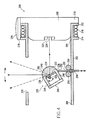
- a scan module 110 supports an oscillates an objective lens 112 that is mounted on a circuit board 114 that also carries four electric coils 116 equally spaced along the four quadrants of the circuit board.
- a support member 118 has a central opening 120 for receiving and retaining a light emitting diode 122 that preferably is a laser-diode.
- a permanent magnet 124 At a side of the support 118, opposite the diode 122, is a permanent magnet 124 that interacts with an electromagnetic field produced by the coils 116 when an electric current is applied.
- the circuit board 114 and support 118 are interconnected by four semi-rigid wires 126 that also carry electric current from a driver circuit to the four coils. By changing the connections between the coils, 1-D or 2-D scan patterns may be selectively achieved.
- Wires 126 preferably are tin-soldered to the circuit board 114 and support 118.
- the material of the wires preferably is a phosphor-bronze alloy, although any other material that conducts electricity and provides semi-rigid support of the circuit board 114 and lens 112 with respect to support 118 may be used.
- Magnet 124 is in the form of a ring, and may be magnetized axially.
- the central hole of magnet 124 serves as an aperture stop for the laser beam.
- the permanent magnet 124 may be multiply poled around its circumference.
- the poling of the permanent magnet may be such that there are four poles, with South poles being oriented at 0° and 180° and North poles at 90° and 270° along the circumference.
- the lens and coil assembly will rotate slightly, and hence the semi-rigid wires will begin to form a helix reducing the distance between the lens 112 and the laser beam source 122 to focus the beam.
- the other two coils are energized to oscillate the lens assembly to produce appropriate scanning.
- This invention generally relates to a compact assembly for electro-optically scanning indicia, including a support, a light source such as a laser diode mounted on the support, an oscillatable optical component, and a drive for oscillating the component.
- the component includes a focussing element for focussing a light beam emitted by the light source, and a scan element of one-piece with the focussing element for directing the light beam away from the support.
- the drive includes a permanent magnet mounted for joint oscillation with the component, and an energizable electrical coil mounted on the support. When energized by an energizing drive current, the field produced by the coil interacts with the field produced by the magnet to effect oscillation of the component for scanning the light beam over the indicia, for example, a bar code symbol.
- the novel one-piece optical component is constituted of a light-transmissive material having a first curved surface constituting part of the focussing element and through which the beam enters the component, and a second reflecting surface from which the focused beam is reflected.
- the second surface is coated with a reflective coating and constitutes part of the scan element.
- the component further includes a third curved surface through which the reflected beam exits the component.
- the third surface acts as a correcting element for scan aberration correction.
- the component still further includes extensions of one-piece with the elements. The extensions are operative for holding the permanent magnet.
- the component is mounted on a shaft journaled at opposite ends on the support.
- a biasing element is operatively connected between the component and the support, for constantly exerting a restoring force on the component to return the latter to a neutral position.
- the biasing element is preferably an elongated leaf spring having one end fixed to the component and an opposite spring end movably connected to the support. The opposite spring end passes between a pair of friction posts on the support and slides between the posts during oscillation of the component.
- the light beam entering the component is at a right angle to the beam exiting the component in the neutral position.
- the second reflecting surface preferably lies in a plane oriented at a 45° angle to the beam entering the component.
- the light source is preferably a laser diode received in an open end of the housing.
- the drive coil surrounds the diode.
- a sensor for detecting light reflected from the indicia is mounted on the housing adjacent the coil and the diode.
- symbol and bar code are intended to be broadly construed and to cover not only patterns composed of alternating bars and spaces of various widths, but also other one or two dimensional graphic patterns, as well as alphanumeric characters.
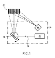
- an outgoing beam 36 is generated in a scanner 30 by a light source 34, such as a laser diode of the like, and directed to impinge upon a bar code symbol 32 that ordinarily is positioned a few inches from the front of the scanner.
- a light source 34 such as a laser diode of the like
- the outgoing beam 36 is scanned by a one-piece, integral or unitary focusing/scanning element 38 so that the scanning beam traverses the symbol to be read. Light reflected from the symbol is received by the scanner 30 and detected by photodetector 44.
- FIG. 4 depicts an embodiment of a compact assembly 200 for electro-optically scanning indicia, in accordance with the present invention.
- the assembly 200 includes a support 202 preferably a cylindrical housing extending a longitudinal axis between opposite ends 204, 206.
- a light source 208 preferably a laser diode, is inserted into open end 204.
- An annular shoulder 210 on the source abuts against an annular flange 212 at the open end 204 to define the installed position of the source.
- the source When electrically activated, the source emits a laser beam along a path toward the indicia to be scanned.
- the support 202 has an annular collar 214 spaced axially from the flange 212.
- An electromagnetic coil 216 is wound around the support between the collar 214 and the flange 212.
- a sensor 218, preferably a photodiode, is mounted radially exteriorly of the flange and the collar, and overlies the coil 216 and the source 208.
- the sensor 218 detects light reflected off the indicia, and generates an electrical signal indicative of the variable intensity of the reflected light from the indicia.
- a filter 220 is positioned over the sensor, an may be a light-transmissive plastic of glass filter, or even a coating of a liquid filter material that is cured in place on the sensor.
- the source 208 includes a aperture plate 222 having a aperture stop 224 through which the emitted beam passes.
- An oscillatable optical component 230 is mounted in the path of the beam, and on a shaft 226 whose opposite ends are journaled in bearings on opposite sides of the cylindrical housing.
- An exit window or port 228 is formed in the side wall of the housing.
- the component 230 is formed of a light-transmissive, optically modifying material, such a synthetic plastic or glass, and includes a focusing element 232 having an outer convexly curved surface 234 through which the emitted beam first enters the component and is focused at a focal point within a working range of distances at which the indicia are located, and a scan element 236 having an outer planar surface 238 coated with a reflective coating preferably a metallic coating formed of nickel, gold of chromium, for reflecting the focused beam away from the coated surface 238.
- the coated surface 238 is oriented at a 45° angle to direct the reflected beam perpendicularly to the incident focused beam.
- the focusing and scan elements are of one-piece with each other, or integrally formed.
- the component 230 also preferably has a connecting element 240 having a outer convexly curved surface 242 through which the reflected beam exits the component and is focused for correction of scan aberration.
- the correcting element is likewise of one-piece, or integral, with the component.
- a permanent magnet 244 is fixedly mounted for joint oscillation with the component 230 on a pair of rear extensions or arms 246, 248, also of one-piece with the component.
- the magnet 244 generates a permanent magnetic field which interacts with the electromagnetic field generated by the coil 216 upon energizing of the coil by an energizing drive current, such as a train of square waves, or any periodic drive signal.
- the component oscillates in alternate circumferential directions about the shaft over arc lengths on the order of 20°-25° in each direction from an equilibrium or neutral position depicted in Figure 4.
- the neutral position is established by a biasing element or flexure 250, preferably a planar leaf spring, having one end 252 fixed to the component, e. g. by a fastener (not shown), and an opposite end 254 slidably mounted between a pair of friction posts 256, 258 mounted on the support.
- the flexure end 254 is frictionally captured, but movable, between the posts.
- the flexure 252 constantly exerts a restoring force on the component to return the latter to the neutral position.
- the flexure During energization of the coil by the drive current, the interacting magnetic fields causes the magnet and the component to oscillate, thereby flexing the flexure.
- the flexure bends in one, and then in an opposite, rounded shape.
- the flexure end 254 slides back and forth through the posts during the bending of the flexure.
- the flexure is constituted of a resilient material such as Mylar® , a thin polyester film about 0.0254 mm (0.001 inch) thick.
- Focusing of the beam is advantageously achieved by the same component that performs the scanning or sweeping of the beam across the indicia.
- the overall assembly occupies a compact volume of the order of 6.5 mm x 6.5 mm x 5.6 mm.
Abstract
Description
- Figure 1
- is a schematic diagram of a scan assembly in accordance with the present invention;
- Figures 2 and 3
- are side and front views of a miniature scanner assembly in accordance with the prior art; and
- Figure 4
- is a sectional side view of a compact scanner assembly, in accordance an embodiment of the present invention.
Claims (10)
- A compact assembly for electro-optically scanning indicia, comprising:a) a support;b) a light source mounted on the support, for emitting a light beam;c) an oscillatable optical component including a focusing element for focusing the light beam, and a scan element of one-piece with the focusing element for directing the light beam away from the support; andd) a drive for oscillating the optical component relative to the support, including a permanent magnet mounted for joint oscillation with the optical component and operative for generating a permanent magnetic field, and an energizable electrical coil mounted on the support and operative, when energized by an energizing drive current, for generating an electromagnetic field that interacts with the permanent magnetic field to effect oscillation of the optical component for scanning the light beam over the indicia.
- The assembly of claim 1, wherein the support is a tubular housing having an open end region, and wherein the light source extends through the open end region,wherein preferably the housing has an annular flange, and wherein the light source including a casing having a shoulder that abuts against the flange, and/orwherein preferably the coil surrounds the open end region and at least part of the light source, and/orwherein preferably the light source is a laser diode, and/orwherein preferably the housing has a window through which the light beam is directed away from the support.
- The assembly of claim 1, wherein the optical component includes a light-transmissive material having a first surface through which the light beam enters the optical component, a second reflecting surface from which the entering light beam is reflected, and a third surface through which the reflected light beam exits the optical component,wherein preferably the first surface is curved and constitutes part of the focusing element, and/orwherein preferably the second reflecting surface is coated with a reflective coating and constitutes part of the scan element, and/orwherein preferably the optical component includes a correcting element for correcting for scan aberration, and wherein the third surface is curved and constitutes part of the correcting element.
- The assembly of claim 2, wherein the optical component includes extensions of one-piece with the elements, for holding the magnet.
- The assembly of claim 1, wherein the support includes a tubular housing, and a shaft journaled at opposite ends on the housing; and wherein the optical component is mounted on the shaft for oscillating movement in alternate circumferential directions about an axis extending along the shaft,said assembly preferably further comprising a biasing element operatively connected between the optical component and the support, for constantly exerting a restoring force on the optical component to return the optical component to a neutral position in a path of the light beam,wherein preferably the biasing element is an elongated spring having one spring end fixed to the optical component, and an opposite spring end movably connected to the support,wherein preferably the support has a pair of friction posts between which the opposite spring end is slidingly mounted.
- A compact assembly for electro-optically scanning indicia, comprising:a) a support extending along a longitudinal axis;b) a light source mounted on the support, for emitting a light beam along the longitudinal axis;c) an oscillatable optical component including a focusing element through which the light beam enters the optical component for focusing the light beam, and a reflecting element of one-piece with the focusing element for reflecting the light beam perpendicularly to the longitudinal axis away from the support as considered in a neutral position of the optical element;d) a drive for oscillating the optical component relative to the support, including a permanent magnet mounted for joint oscillation with the optical component and operative for generating a permanent magnetic field, and an energizable electrical coil mounted on the support and operative, when energized by an energizing drive current, for generating an electromagnetic field that interacts with the permanent magnetic field to effect oscillation of the optical component for scanning the light beam over the indicium; ande) a biasing element operatively connected between the optical component and the support, for constantly exerting a restoring force on the optical component to return the optical component to the neutral position.
- An optical component for use in scanning a light beam over indicia, comprising:a) a light-transmissive block having a first curved surface through which the light beam enters the block and is focused, a second generally planar surface impinged by the focused light beam, and a third surface from which the light beam exits the block; andb) a reflective coating on the second surface for reflecting the impinging light beam to and through the third surface, the exiting light beam being perpendicular to the entering light beam.
- A compact assembly for electro-optically scanning indicia, comprising:a) a support;b) a light source mounted on the support, for emitting a light beam;c) an oscillatable optical component including a focusing element for focusing the light beam, and a scan element of one-piece with the focusing element for directing the light beam away from the support;d) a drive for oscillating the optical component relative to the support, including a permanent magnet mounted for joint oscillation with the optical component and operative for generating a permanent magnetic field, and an energizable electrical coil mounted on the support and operative, when energized by an energizing drive current, for generating an electromagnetic field that interacts with the permanent magnetic field to effect oscillation of the optical component for scanning the light beam over the indicia; ande) a sensor mounted adjacent the light source on the support, for detecting light reflected from the indicia.
- Method of focusing a laser beam in an electro-optical scanning assembly, comprising the steps of:a) mounting a laser source for emitting the laser beam on a support; andb) mounting an optical component on the support in a spaced relation to the laser source, the component including a focusing element for focusing the laser beam, and a scan element of one-piece with the focusing element for directing the focused beam away from the support.
- A compact assembly for electro-optically scanning indicia, comprising:a) a light source for emitting a light beam;b) an oscillatable optical component including a focusing element for focusing the light beam, and a scan element of one-piece with the focusing element for directing the light beam ; andc) a drive for oscillating the optical component.
Applications Claiming Priority (2)
| Application Number | Priority Date | Filing Date | Title |
|---|---|---|---|
| US09/724,745 US6575370B1 (en) | 1990-05-08 | 2000-08-31 | Electro-optical scanning assembly with one-piece, oscillatable, focusing/scan element |
| US724745 | 2000-08-31 |
Publications (3)
| Publication Number | Publication Date |
|---|---|
| EP1184803A2 true EP1184803A2 (en) | 2002-03-06 |
| EP1184803A3 EP1184803A3 (en) | 2003-04-02 |
| EP1184803B1 EP1184803B1 (en) | 2007-10-17 |
Family
ID=24911732
Family Applications (1)
| Application Number | Title | Priority Date | Filing Date |
|---|---|---|---|
| EP01120999A Expired - Lifetime EP1184803B1 (en) | 2000-08-31 | 2001-08-31 | Electro-optical scanning assembly with one-piece oscillatable focussing/scan element |
Country Status (7)
| Country | Link |
|---|---|
| US (1) | US6575370B1 (en) |
| EP (1) | EP1184803B1 (en) |
| JP (1) | JP4763178B2 (en) |
| CN (1) | CN1220093C (en) |
| AT (1) | ATE376221T1 (en) |
| AU (1) | AU779933B2 (en) |
| DE (1) | DE60130950T2 (en) |
Families Citing this family (10)
| Publication number | Priority date | Publication date | Assignee | Title |
|---|---|---|---|---|
| US7086596B2 (en) * | 2003-01-09 | 2006-08-08 | Hand Held Products, Inc. | Decoder board for an optical reader utilizing a plurality of imaging formats |
| US8002183B2 (en) * | 2005-10-20 | 2011-08-23 | Metrologic Instruments, Inc. | Scanner flipper integrity indicator |
| US7614561B2 (en) * | 2005-12-16 | 2009-11-10 | Metrologic Instruments, Inc. | Scanner flipper oscillation frequency detection and adjustment thereof |
| US8294969B2 (en) * | 2009-09-23 | 2012-10-23 | Metrologic Instruments, Inc. | Scan element for use in scanning light and method of making the same |
| US8390909B2 (en) | 2009-09-23 | 2013-03-05 | Metrologic Instruments, Inc. | Molded elastomeric flexural elements for use in a laser scanning assemblies and scanners, and methods of manufacturing, tuning and adjusting the same |
| US8059324B2 (en) * | 2009-09-23 | 2011-11-15 | Metrologic Instruments, Inc. | Scan element for use in scanning light and method of making the same |
| US20110297747A1 (en) * | 2010-06-07 | 2011-12-08 | Interactive Lot Technologies Inc. | Custom scanning device and automated car auction facility management |
| US8915439B2 (en) | 2012-02-06 | 2014-12-23 | Metrologic Instruments, Inc. | Laser scanning modules embodying silicone scan element with torsional hinges |
| US8746563B2 (en) | 2012-06-10 | 2014-06-10 | Metrologic Instruments, Inc. | Laser scanning module with rotatably adjustable laser scanning assembly |
| USD910021S1 (en) * | 2019-01-11 | 2021-02-09 | Zebra Technologies Corporation | Data capture device |
Citations (10)
| Publication number | Priority date | Publication date | Assignee | Title |
|---|---|---|---|---|
| US4387297A (en) * | 1980-02-29 | 1983-06-07 | Symbol Technologies, Inc. | Portable laser scanning system and scanning methods |
| DE3408114A1 (en) * | 1984-03-06 | 1985-09-19 | Messerschmitt Boelkow Blohm | Lens combination for a catadioptric reflecting telescope |
| EP0367300A2 (en) * | 1985-02-28 | 1990-05-09 | Symbol Technologies, Inc. | Portable laser diode scanning head |
| US5015831A (en) * | 1988-11-07 | 1991-05-14 | Photographic Sciences Corporation | Scan modules for bar code readers and the like in which scan elements are flexurally supported |
| US5187353A (en) * | 1990-04-18 | 1993-02-16 | Symbol Technologies, Inc. | Bar code symbol scanner utilizing monitor photodiode of laser diode package as a photoreceiver |
| US5521367A (en) * | 1992-10-08 | 1996-05-28 | Symbol Technologies, Inc. | Fiber optic barcode reader with piezoelectric element |
| US5661290A (en) * | 1988-05-11 | 1997-08-26 | Symbol Technologies, Inc. | Scanner with flexibly supported light emitter |
| US5705799A (en) * | 1990-05-08 | 1998-01-06 | Symbol Technologies, Inc. | Miniature optical scanning assembly for barcode readers |
| GB2324168A (en) * | 1997-04-11 | 1998-10-14 | Geoffrey Owen | Optical deflector and beam splitter |
| US5949068A (en) * | 1997-10-07 | 1999-09-07 | Telxon Corporation | Optical reader for scanning optical indicia by way of varying object distance |
Family Cites Families (4)
| Publication number | Priority date | Publication date | Assignee | Title |
|---|---|---|---|---|
| JPH0321908A (en) * | 1989-06-19 | 1991-01-30 | Fujitsu Ltd | Photosemiconductor module |
| US5581067A (en) * | 1990-05-08 | 1996-12-03 | Symbol Technologies, Inc. | Compact bar code scanning module with shock protection |
| JP2603883B2 (en) * | 1990-11-21 | 1997-04-23 | 株式会社テスコ | Light beam scanning device for barcode scanner |
| JP3467603B2 (en) | 1994-03-17 | 2003-11-17 | 株式会社オプトエレクトロニクス | Vibrating mirror scanning device |
-
2000
- 2000-08-31 US US09/724,745 patent/US6575370B1/en not_active Expired - Fee Related
-
2001
- 2001-08-09 AU AU57937/01A patent/AU779933B2/en not_active Ceased
- 2001-08-31 JP JP2001263894A patent/JP4763178B2/en not_active Expired - Lifetime
- 2001-08-31 DE DE60130950T patent/DE60130950T2/en not_active Expired - Lifetime
- 2001-08-31 AT AT01120999T patent/ATE376221T1/en not_active IP Right Cessation
- 2001-08-31 EP EP01120999A patent/EP1184803B1/en not_active Expired - Lifetime
- 2001-08-31 CN CNB011252456A patent/CN1220093C/en not_active Expired - Fee Related
Patent Citations (11)
| Publication number | Priority date | Publication date | Assignee | Title |
|---|---|---|---|---|
| US4387297A (en) * | 1980-02-29 | 1983-06-07 | Symbol Technologies, Inc. | Portable laser scanning system and scanning methods |
| US4387297B1 (en) * | 1980-02-29 | 1995-09-12 | Symbol Technologies Inc | Portable laser scanning system and scanning methods |
| DE3408114A1 (en) * | 1984-03-06 | 1985-09-19 | Messerschmitt Boelkow Blohm | Lens combination for a catadioptric reflecting telescope |
| EP0367300A2 (en) * | 1985-02-28 | 1990-05-09 | Symbol Technologies, Inc. | Portable laser diode scanning head |
| US5661290A (en) * | 1988-05-11 | 1997-08-26 | Symbol Technologies, Inc. | Scanner with flexibly supported light emitter |
| US5015831A (en) * | 1988-11-07 | 1991-05-14 | Photographic Sciences Corporation | Scan modules for bar code readers and the like in which scan elements are flexurally supported |
| US5187353A (en) * | 1990-04-18 | 1993-02-16 | Symbol Technologies, Inc. | Bar code symbol scanner utilizing monitor photodiode of laser diode package as a photoreceiver |
| US5705799A (en) * | 1990-05-08 | 1998-01-06 | Symbol Technologies, Inc. | Miniature optical scanning assembly for barcode readers |
| US5521367A (en) * | 1992-10-08 | 1996-05-28 | Symbol Technologies, Inc. | Fiber optic barcode reader with piezoelectric element |
| GB2324168A (en) * | 1997-04-11 | 1998-10-14 | Geoffrey Owen | Optical deflector and beam splitter |
| US5949068A (en) * | 1997-10-07 | 1999-09-07 | Telxon Corporation | Optical reader for scanning optical indicia by way of varying object distance |
Non-Patent Citations (1)
| Title |
|---|
| No Search * |
Also Published As
| Publication number | Publication date |
|---|---|
| EP1184803B1 (en) | 2007-10-17 |
| AU5793701A (en) | 2002-03-07 |
| JP4763178B2 (en) | 2011-08-31 |
| US6575370B1 (en) | 2003-06-10 |
| EP1184803A3 (en) | 2003-04-02 |
| JP2002131686A (en) | 2002-05-09 |
| CN1371009A (en) | 2002-09-25 |
| CN1220093C (en) | 2005-09-21 |
| DE60130950T2 (en) | 2008-07-24 |
| DE60130950D1 (en) | 2007-11-29 |
| ATE376221T1 (en) | 2007-11-15 |
| AU779933B2 (en) | 2005-02-17 |
Similar Documents
| Publication | Publication Date | Title |
|---|---|---|
| US5486944A (en) | Scanner module for symbol scanning system | |
| US5811773A (en) | Scanner with flexible flat cable electrically connected to light emitter | |
| EP1296277B1 (en) | One piece optical assembly for low cost optical scanner | |
| US5422471A (en) | Scanning device for scanning a target, scanning motor for the device and a method of utilization thereof | |
| EP0788068B1 (en) | Scanning arrangement | |
| US6142379A (en) | Compact bar code scanner with scan mirror jointly movable with drive component | |
| US5665954A (en) | Electro-optical scanner module having dual electro-magnetic coils | |
| US6491222B1 (en) | Optical path design for scanning assembly in compact bar code readers | |
| US5386107A (en) | Scanning arrangement and method in which the focus is varied in operative correlation with the scanning angle | |
| JP3089147U (en) | Scanning module for reading display symbols electro-optically | |
| AU780839B2 (en) | Compact dual optical and scan modules in bar code readers | |
| US6722566B1 (en) | Electro-optical scan module using selectable mirrors | |
| AU779933B2 (en) | Electro-optical scanning assembly with one-piece oscillatable focussing/scan element | |
| EP1308875B1 (en) | High speed laser scan module with folded beam path | |
| CA2111934C (en) | Scanner module for symbol scanning system | |
| JP4435469B2 (en) | High speed laser scanning module with reflected beam path | |
| US6702184B2 (en) | Collection optics for low profile single line scanning assembly in compact bar code readers | |
| US7017815B2 (en) | Compact externally-driven scanner |
Legal Events
| Date | Code | Title | Description |
|---|---|---|---|
| PUAI | Public reference made under article 153(3) epc to a published international application that has entered the european phase |
Free format text: ORIGINAL CODE: 0009012 |
|
| AK | Designated contracting states |
Kind code of ref document: A2 Designated state(s): AT BE CH CY DE DK ES FI FR GB GR IE IT LI LU MC NL PT SE TR |
|
| AX | Request for extension of the european patent |
Free format text: AL;LT;LV;MK;RO;SI |
|
| PUAL | Search report despatched |
Free format text: ORIGINAL CODE: 0009013 |
|
| AK | Designated contracting states |
Kind code of ref document: A3 Designated state(s): AT BE CH CY DE DK ES FI FR GB GR IE IT LI LU MC NL PT SE TR |
|
| AX | Request for extension of the european patent |
Extension state: AL LT LV MK RO SI |
|
| RIC1 | Information provided on ipc code assigned before grant |
Ipc: 7G 06K 7/10 A Ipc: 7G 02B 26/10 B Ipc: 7G 02B 17/08 B |
|
| 17P | Request for examination filed |
Effective date: 20031001 |
|
| AKX | Designation fees paid |
Designated state(s): AT BE CH CY DE DK ES FI FR GB GR IE IT LI LU MC NL PT SE TR |
|
| 17Q | First examination report despatched |
Effective date: 20031120 |
|
| GRAP | Despatch of communication of intention to grant a patent |
Free format text: ORIGINAL CODE: EPIDOSNIGR1 |
|
| GRAS | Grant fee paid |
Free format text: ORIGINAL CODE: EPIDOSNIGR3 |
|
| GRAA | (expected) grant |
Free format text: ORIGINAL CODE: 0009210 |
|
| AK | Designated contracting states |
Kind code of ref document: B1 Designated state(s): AT BE CH CY DE DK ES FI FR GB GR IE IT LI LU MC NL PT SE TR |
|
| REG | Reference to a national code |
Ref country code: GB Ref legal event code: FG4D |
|
| REG | Reference to a national code |
Ref country code: CH Ref legal event code: EP |
|
| REG | Reference to a national code |
Ref country code: IE Ref legal event code: FG4D |
|
| REF | Corresponds to: |
Ref document number: 60130950 Country of ref document: DE Date of ref document: 20071129 Kind code of ref document: P |
|
| ET | Fr: translation filed | ||
| NLV1 | Nl: lapsed or annulled due to failure to fulfill the requirements of art. 29p and 29m of the patents act | ||
| PG25 | Lapsed in a contracting state [announced via postgrant information from national office to epo] |
Ref country code: LI Free format text: LAPSE BECAUSE OF FAILURE TO SUBMIT A TRANSLATION OF THE DESCRIPTION OR TO PAY THE FEE WITHIN THE PRESCRIBED TIME-LIMIT Effective date: 20071017 Ref country code: SE Free format text: LAPSE BECAUSE OF FAILURE TO SUBMIT A TRANSLATION OF THE DESCRIPTION OR TO PAY THE FEE WITHIN THE PRESCRIBED TIME-LIMIT Effective date: 20080117 Ref country code: ES Free format text: LAPSE BECAUSE OF FAILURE TO SUBMIT A TRANSLATION OF THE DESCRIPTION OR TO PAY THE FEE WITHIN THE PRESCRIBED TIME-LIMIT Effective date: 20080128 Ref country code: CH Free format text: LAPSE BECAUSE OF FAILURE TO SUBMIT A TRANSLATION OF THE DESCRIPTION OR TO PAY THE FEE WITHIN THE PRESCRIBED TIME-LIMIT Effective date: 20071017 Ref country code: NL Free format text: LAPSE BECAUSE OF FAILURE TO SUBMIT A TRANSLATION OF THE DESCRIPTION OR TO PAY THE FEE WITHIN THE PRESCRIBED TIME-LIMIT Effective date: 20071017 |
|
| REG | Reference to a national code |
Ref country code: CH Ref legal event code: PL |
|
| PG25 | Lapsed in a contracting state [announced via postgrant information from national office to epo] |
Ref country code: PT Free format text: LAPSE BECAUSE OF FAILURE TO SUBMIT A TRANSLATION OF THE DESCRIPTION OR TO PAY THE FEE WITHIN THE PRESCRIBED TIME-LIMIT Effective date: 20080317 |
|
| PG25 | Lapsed in a contracting state [announced via postgrant information from national office to epo] |
Ref country code: AT Free format text: LAPSE BECAUSE OF FAILURE TO SUBMIT A TRANSLATION OF THE DESCRIPTION OR TO PAY THE FEE WITHIN THE PRESCRIBED TIME-LIMIT Effective date: 20071017 |
|
| PG25 | Lapsed in a contracting state [announced via postgrant information from national office to epo] |
Ref country code: DK Free format text: LAPSE BECAUSE OF FAILURE TO SUBMIT A TRANSLATION OF THE DESCRIPTION OR TO PAY THE FEE WITHIN THE PRESCRIBED TIME-LIMIT Effective date: 20071017 |
|
| PLBE | No opposition filed within time limit |
Free format text: ORIGINAL CODE: 0009261 |
|
| STAA | Information on the status of an ep patent application or granted ep patent |
Free format text: STATUS: NO OPPOSITION FILED WITHIN TIME LIMIT |
|
| PG25 | Lapsed in a contracting state [announced via postgrant information from national office to epo] |
Ref country code: BE Free format text: LAPSE BECAUSE OF FAILURE TO SUBMIT A TRANSLATION OF THE DESCRIPTION OR TO PAY THE FEE WITHIN THE PRESCRIBED TIME-LIMIT Effective date: 20071017 |
|
| 26N | No opposition filed |
Effective date: 20080718 |
|
| PG25 | Lapsed in a contracting state [announced via postgrant information from national office to epo] |
Ref country code: GR Free format text: LAPSE BECAUSE OF FAILURE TO SUBMIT A TRANSLATION OF THE DESCRIPTION OR TO PAY THE FEE WITHIN THE PRESCRIBED TIME-LIMIT Effective date: 20080118 |
|
| PG25 | Lapsed in a contracting state [announced via postgrant information from national office to epo] |
Ref country code: FI Free format text: LAPSE BECAUSE OF FAILURE TO SUBMIT A TRANSLATION OF THE DESCRIPTION OR TO PAY THE FEE WITHIN THE PRESCRIBED TIME-LIMIT Effective date: 20071017 |
|
| PG25 | Lapsed in a contracting state [announced via postgrant information from national office to epo] |
Ref country code: MC Free format text: LAPSE BECAUSE OF NON-PAYMENT OF DUE FEES Effective date: 20080831 |
|
| PG25 | Lapsed in a contracting state [announced via postgrant information from national office to epo] |
Ref country code: CY Free format text: LAPSE BECAUSE OF FAILURE TO SUBMIT A TRANSLATION OF THE DESCRIPTION OR TO PAY THE FEE WITHIN THE PRESCRIBED TIME-LIMIT Effective date: 20071017 Ref country code: IE Free format text: LAPSE BECAUSE OF NON-PAYMENT OF DUE FEES Effective date: 20080901 |
|
| PGFP | Annual fee paid to national office [announced via postgrant information from national office to epo] |
Ref country code: FR Payment date: 20090806 Year of fee payment: 9 |
|
| PGFP | Annual fee paid to national office [announced via postgrant information from national office to epo] |
Ref country code: DE Payment date: 20090831 Year of fee payment: 9 Ref country code: GB Payment date: 20090708 Year of fee payment: 9 |
|
| PG25 | Lapsed in a contracting state [announced via postgrant information from national office to epo] |
Ref country code: LU Free format text: LAPSE BECAUSE OF NON-PAYMENT OF DUE FEES Effective date: 20080831 |
|
| PG25 | Lapsed in a contracting state [announced via postgrant information from national office to epo] |
Ref country code: TR Free format text: LAPSE BECAUSE OF FAILURE TO SUBMIT A TRANSLATION OF THE DESCRIPTION OR TO PAY THE FEE WITHIN THE PRESCRIBED TIME-LIMIT Effective date: 20071017 |
|
| PG25 | Lapsed in a contracting state [announced via postgrant information from national office to epo] |
Ref country code: IT Free format text: LAPSE BECAUSE OF NON-PAYMENT OF DUE FEES Effective date: 20080831 |
|
| GBPC | Gb: european patent ceased through non-payment of renewal fee |
Effective date: 20100831 |
|
| REG | Reference to a national code |
Ref country code: FR Ref legal event code: ST Effective date: 20110502 |
|
| REG | Reference to a national code |
Ref country code: DE Ref legal event code: R119 Ref document number: 60130950 Country of ref document: DE Effective date: 20110301 |
|
| PG25 | Lapsed in a contracting state [announced via postgrant information from national office to epo] |
Ref country code: DE Free format text: LAPSE BECAUSE OF NON-PAYMENT OF DUE FEES Effective date: 20110301 Ref country code: FR Free format text: LAPSE BECAUSE OF NON-PAYMENT OF DUE FEES Effective date: 20100831 |
|
| PG25 | Lapsed in a contracting state [announced via postgrant information from national office to epo] |
Ref country code: GB Free format text: LAPSE BECAUSE OF NON-PAYMENT OF DUE FEES Effective date: 20100831 |