EP1187375A1 - Data transmission system using a human body as a signal transmission path - Google Patents
Data transmission system using a human body as a signal transmission path Download PDFInfo
- Publication number
- EP1187375A1 EP1187375A1 EP01121387A EP01121387A EP1187375A1 EP 1187375 A1 EP1187375 A1 EP 1187375A1 EP 01121387 A EP01121387 A EP 01121387A EP 01121387 A EP01121387 A EP 01121387A EP 1187375 A1 EP1187375 A1 EP 1187375A1
- Authority
- EP
- European Patent Office
- Prior art keywords
- signal
- ground
- garment
- transmitter
- data transmission
- Prior art date
- Legal status (The legal status is an assumption and is not a legal conclusion. Google has not performed a legal analysis and makes no representation as to the accuracy of the status listed.)
- Granted
Links
Images


Classifications
-
- A—HUMAN NECESSITIES
- A61—MEDICAL OR VETERINARY SCIENCE; HYGIENE
- A61B—DIAGNOSIS; SURGERY; IDENTIFICATION
- A61B5/00—Measuring for diagnostic purposes; Identification of persons
- A61B5/0002—Remote monitoring of patients using telemetry, e.g. transmission of vital signals via a communication network
- A61B5/0026—Remote monitoring of patients using telemetry, e.g. transmission of vital signals via a communication network characterised by the transmission medium
- A61B5/0028—Body tissue as transmission medium, i.e. transmission systems where the medium is the human body
-
- G—PHYSICS
- G07—CHECKING-DEVICES
- G07C—TIME OR ATTENDANCE REGISTERS; REGISTERING OR INDICATING THE WORKING OF MACHINES; GENERATING RANDOM NUMBERS; VOTING OR LOTTERY APPARATUS; ARRANGEMENTS, SYSTEMS OR APPARATUS FOR CHECKING NOT PROVIDED FOR ELSEWHERE
- G07C9/00—Individual registration on entry or exit
- G07C9/20—Individual registration on entry or exit involving the use of a pass
- G07C9/28—Individual registration on entry or exit involving the use of a pass the pass enabling tracking or indicating presence
-
- H—ELECTRICITY
- H04—ELECTRIC COMMUNICATION TECHNIQUE
- H04B—TRANSMISSION
- H04B13/00—Transmission systems characterised by the medium used for transmission, not provided for in groups H04B3/00 - H04B11/00
- H04B13/005—Transmission systems in which the medium consists of the human body
Definitions
- the present invention relates to a data transmission system using a human body as a signal path, and more particularly to a system composed of a wearable transmitter, a receiver adapted to be connected to an associated equipment which utilize data transmitted from the transmitter, and a garment integrally holding two electrodes for passing the data through the human body.
- EP application No. 00113564.9 discloses a data transmission system using the human body as a signal path.
- the system includes a portable transmitter in the form of a wrist watch to be worn on a user, and a signal receiver.
- the transmitter has a pair of electrodes on the back of the wrist watch for direct contact with the skin of the user.
- One electrode acts as a signal electrode which is connected through a portion of the user's body to a touch electrode of the signal receiver, while the other electrode acts as a ground electrode which is coupled through the other portion of the user's body to a circuit ground of the signal receiver to complete a signal path through the user's body for data transmission from the wrist watch to the signal receiver.
- the present invention has been achieved to provide a data transmission system which is capable of assuring successful data transmission without requiring a special attention to the user.
- the system in accordance with the present invention comprises a transmitter adapted to be carried by the user and a receiver adapted to be connected to an associated equipment which utilizes data transmitted from the transmitter.
- the transmitter has a ground electrode to be placed in close proximity to the human body, a signal electrode to be placed also in close proximity to the human body in a spatially spaced relation from the ground electrode, a data memory storing first data, a first modulator for converting the first data into a first modulated voltage signal, and a first signal transmitter which applies the first modulated voltage signal across the signal electrode and the ground electrode.
- the receiver includes a circuit ground adapted to be connected to the ground, a touch electrode adapted for direct contact with a portion of the human body carrying the transmitter, a signal detector connected across the signal electrode and the circuit ground to detect the first modulated voltage signal, and a demodulator which converts the first modulated voltage signal back into the first data.
- the characterizing feature of the present invention resides in that the system includes a garment which is adapted to be worn by a user and integrates the ground and signal electrodes in such a manner that at least one of the electrodes is kept in a closely facing relation to the skin of the user, thereby establishing an electrical path extending through a portion of the human body for signal transmission from the transmitter to the receiver. With the integration of the two electrodes into the garment, the user wearing the garment as an everyday clothes or uniform such as a white gown can be easy and convenient to carry the transmitter for successful transmission of the data to the receiver.
- each of the ground and signal electrodes is formed by a plurality of electrically conductive threads and is sewed to be integrated into the garment.
- the electrodes can be easily integrated into the garment and cannot sacrifice comfortableness of the garment.
- Each electrode made of the electrically conductive threads can be woven into a fabric so as to be lined on the garment.
- the electrode of the conductive threads can be woven into an indispensable part of the garment. With the use of the electrical conductive threads, the garment provided with the resulting electrodes can be washed like ordinary clothes, which enhances availability of the system.
- the ground electrode is preferred to be located on the garment closer to the foot of the user than the signal electrode for establishing a consistent electrical path through the human body. That is, the electrical path is composed of a first fraction path extending from the ground electrode down to the foot of the user and through the ground to the circuit ground of the receiver, and a second fraction path extending from the signal electrode towards and through a finger of the user to the touch electrode of the receiver without interfering the first fraction path, thereby assuring efficient and reliable data transmission.
- the transmitter has a case which accommodates an electrical circuitry realizing the first modulator and the first signal transmitter, and which is formed as a separate article from the electrodes.
- the case is provided with terminals for electrically connecting the circuitry with the ground and signal electrodes.
- the garment is additionally provided with a ground lead and a signal lead which extend respectively from the ground and signal electrodes for connection with the terminals of the case.
- Both of the ground and signal leads are formed by a strand of the electrically conductive threads and are sewed on the garment.
- the leads can be also easily and consistently integrated into the garment to retain comfortableness of the garment.
- a coupling member is included in the system to make the case detachable from the garment and at the same time make the electrical circuitry detachable from the electrodes, i.e., the corresponding leads.
- the coupling member may be realized by a spring-loaded clip which is pivotally supported to the case so as to be movable between a pinching position and a release position.
- the clip is formed with the terminals which are electrically isolated from each other for connection respectively with the ground and signal leads at the pinching position.
- the coupling member may comprise a pair of first fasteners each composed of one of a socket and a ball forming a snap button for mounting the case to the garment, and a pair of second fasteners each composed of the other of the socket and the ball.
- the first fasteners are fixed on the case and connected across the first signal transmitter of the circuitry, while the second fasteners are fixed on the garment and are permanently connected to respectively to the ground and signal electrodes.
- the second fasteners are preferably held in direct contact with the ground and signal electrodes, respectively formed of the electrically conductive threads, thereby substantially eliminating the leads from the garment.
- the ground and signal electrodes may be in the form of annular bands provided inside of a sleeve of the garment in a spaced relation from each other along the length of the sleeve.
- the case is made water-tight for sealing the electric circuitry so that the garment can be washed like ordinal clothes even with the case.
- the case may be in the form of a plate which encapsulate the circuitry and a battery energizing the circuitry.
- the plate can be utilized also as a nameplate as is usual with the white gown worn by a physician, nurse, and a laboratory worker.
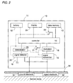
- the system includes a wearable transmitter 10 adapted to be worn on the human body, and a receiver 40 adapted to be connected to an equipment such as a personal computer 60 which utilizes data transmitted from the transmitter for controlled operation of the computer 60, for example, a verified log-in of the user.
- the transmitter 10 is connected to a ground electrode 31 and a signal electrode 32 which are integrated into a garment 30 worn by a user in close proximity to the skin of the user.
- a signal path is established which extends from the signal electrode 32 through a portion of the user's body, the touch electrode 41, an internal circuit of the receiver 40, a circuit ground 49 of the receiver 40, the ground G, the other portion of the user's body, the ground electrode 31 and an internal circuit of the transmitter 10 .
- the signal path extending through the human body is indicated by dotted lines.
- a voltage signal applied across the electrodes 31 and 32 is transmitted to the receiver 40 when the user touches the touch electrode 41.
- the circuit ground of the receiver 40 is connected to the ground G through a ground line 64 common to the computer 60 for the sake of simplicity.
- the circuit ground may be capacitively connected to the ground G or even capacitively connected directly to the major portion of the user's body for establishing the signal path.
- the transmitter 10 includes an electric circuitry and a battery 12 which are accommodated within a case 11.
- the circuitry includes a data memory 13 storing data to be transmitted, a controller 14, a modulator 15 modulating the data into a modulated voltage signal, a signal transmitter 16 applying the modulated voltage signal across the signal electrode 32 and the ground electrode 31 on the garment 30.
- a signal detector 20 which is connected to detect a start signal transmitted from the receiver 40 through the signal electrode 32. The start signal is received across the signal electrode 32 and a circuit ground 19. The circuit ground 19 may be connected to the ground electrode 31. Only the controller 14 and the signal detector 20 are constantly energized by the battery 12 to be ready for detecting the start signal from the receiver 40.
- the controller 14 In the non-operative condition where the transmitter 10 is not transmitting the data, the controller 14 is kept in a sleep mode of consuming less electric current from the battery 12.
- the signal detector 20 wakes up the controller 14 which in turn energizes the data memory 13, the modulator 15, and the signal transmitter 16 to apply the modulated voltage signal across the signal electrode 32 and the ground electrode 31 for initiating the data transmission.
- the controller 14 incorporates a timer which starts upon detection of the start signal to provide a predetermined time during which the data is transmitted. After the elapse of the predetermined time, the controller 14 responds to deenergize the modulator 15, the signal transmitter 16 and the data memory 13.
- the controller 14 includes power switches 21 and 22 which are actuated by the signal detector 20 and the timer to selectively energize and deenergize the modulator 15, the signal transmitter 16 and the data memory 13. Dotted lines in FIG. 2 show power supply lines from the battery 12. Thus, after transmitting the data, the controller 14 goes back into the sleep mode of consuming less current or energy but being kept ready to detect of the start signal for another data transmission.
- the transmitter 10 optionally includes a display 24 for visual indication of the data stored in the data memory 15.
- the receiver 40 includes various circuits connected to the touch electrode 41 on the exterior of a housing of the receiver.
- the circuits are energized by a power source 61 provided in the computer 60 to which the receiver 40 is attached.
- the circuits are commonly connected to a circuit ground 49 which is in turn connected to a ground terminal 69 of the computer for connection with the ground.
- the circuits include a touch sensor 42 which is connected to the touch electrode 41 to give a touch signal when the touch electrode 41 is touched by the user's body.
- Also included in the circuits are a start signal generator 43, a signal detector 44, a demodulator 45, and a controller 46 which controls the operations of the circuits.
- the signal transmitter 43 applies the start signal to the touch electrode 41 in response to the touch signal.
- the signal detector 44 detects the modulated voltage signal which is transmitted from the transmitter 10 and received across the touch electrode 41 and the circuit ground 49.
- the modulated voltage signal thus detected is demodulated at the demodulator 45 to derive the first data which is then fed to the computer 60 to be processed thereat.
- the first data includes a user's identification code which is verified at a processor 62 of the computer with reference to various codes assigned to different users and stored in a data memory 63. When the user's ID is verified as a correct one, the computer completes the log-in sequence to permit the access by the user.
- the controller 46 and the touch sensor 42 are energized to be ready for detection of the touching.
- the touch sensor 42 gives the touch signal to the controller 46 which responds to close switches 51 and 52 to energize the signal transmitter 43, the signal detector 44, and the demodulator 45, thereby generating the start signal and making the circuits ready for receiving the data from the transmitter 10.
- the controller 46 also includes a timer which starts, upon receiving the touch signal, to provide a predetermined time interval during which the data transmission from the first transceiver 10 is expected to complete.
- the controller 46 responds to open the switches 51 and 52, deenergizing the signal transmitter 43, the signal detector 44, and the demodulator 45.
- the receiver 40 is kept in a sleep mode of consuming less electricity until the touch electrode 41 is touched.
- Dotted lines in FIG. 3 show power supply lines.
- the receiver 40 further includes an interface 54 in the form of the USB for transferring the data to the computer 60 as well as for receiving the power from a power supply 61.
- the transmitter 10 and the receiver 40 are designed to effect a bilateral data transmission therebetween.
- the transmitter 10 additionally includes a demodulator 25 for demodulating data transmitted from the receiver 40 and that the receiver 40 additionally includes a modulator 47 for modulating the data to be transmitted from the receiver 40.
- the modulator 47 of gives a modulated voltage signal indicative of the data to be transmitted to the transmitter 10.
- the signal transmitter 43 of the receiver 40 is responsible for applying the modulated voltage signal to the touch electrode 41 for data transmission back to the transmitter 10.
- the touch sensor 42 provides a touch signal in response to which the controller 46 energizes the modulator 47, the signal transmitter 43, the demodulator 45, and the signal detector 44.
- the controller 46 retrieves the data from the data memory 63 of the computer 60 and instructs to give and apply the modulated voltage signal indicative of the data.
- the controller 14 of the transmitter 10 activates the data memory 13 and performs a suitable processing of the data from the data memory 13 in consideration of the data received from the receiver 40.
- the controller 14 updates the data of the data memory 13 depending upon the result of the processing.
- the controller 14 activates the modulator 15 and the signal transmitter 16 so as to transmit the modulated voltage signal indicative of the updated data to the receiver 40 through the electrodes 31 and 32.
- the modulated voltage signal received at the receiver 40 is converted into the data which is utilized by the controller 46 for a controlled operation of the computer or passed to another equipment to be processed thereat for a specific operation of the equipment.
- the two-way data transmission is made between the transmitter and the receiver in a half-duplex manner.
- the system may be designed to have more than one data transmission cycles in which the one-way data transmission from either of the transmitter and the receiver repeats twice or more. In such case, the data in the data memory 13 of the transmitter 10 is modified or updated by the data transmitted from the receiver 40.
- the transmitter 10 is kept in the sleep mode until the modulated voltage signal is received from the receiver 40, and comes back again in the sleep mode after the data transmission between the transmitter and the receiver is completed.
- the data memory 13, the modulator 15, the signal transmitter 16, and the demodulator 21 are energized by closure of the switches 21 and 22 only for a predetermined time period starting from receiving the modulated voltage signal from the receiver. It is within the predetermined time period that the data transmission between the transmitter and the receiver is completed.
- the receiver is kept in the sleep mode until the touch electrode 41 is touched by the human body, and come back to the sleep mode after the data transmission between the first and second transceivers are completed.
- the signal transmitter 43, the modulator 47, the signal detector 44, and the demodulator 45 are energized by closure of switches 51 and 52 only for a predetermined time period starting from the touch electrode being touched.
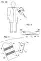
- the garment 30 to which the electrodes 31 and 32 are attached is selected, for example, as a white gown that is always worn by a particular user like a physician, nurse, and laboratory worker while engaging a job requiring a verification of the user.
- the garment 30 is not limited to the white gown and may take various types of the clothes such as a uniform for an office, factory, school, and the like organization or group.
- Each of the ground electrode 31 and the signal electrode 32 is in the form of a fabric made by electrically conductive threads and is sewed on the inner surface of the garment 30 with the signal electrode 32 disposed at the shoulders of the garment 30 and with the ground electrode 31 disposed around the lower part of the garment corresponding to a hip and buttocks of the user, as shown in FIGS. 4 and 5.
- the electrodes may be woven into the garment as indispensable parts thereof. The above selected location of the electrodes 31 and 32 is particularly effective when the user access the computer 60 while sitting on a chair as shown in FIG. 6.
- the ground electrode 31 receives a counter force from the seat of the chair to be pressed against the buttocks of the user, while the signal electrode 32 is pressed against the shoulders of the user with the help of weight of the garment for reliable electrical connection of the electrodes to the human body. It is noted in this connection that the ground electrode 31 is located closer to the foot of the user than the signal electrode 32 along the signal path extending through the human body so that the path extending from the signal electrode 32 toward the finger of the user can be substantially free from, i.e., cannot be substantially interfered with the path extending from the ground electrode 31 to the foot of the user for reliable signal transmission between the transmitter 10 and the receiver 40.
- the case 11 of the transmitter 10 is formed into a nameplate which is made water-tight and accommodates therein the electric circuitry 28 forming the various functional circuits and elements as shown in FIG. 2, and the battery 12 energizing the circuits.
- the case 11 is provided with a spring-loaded clip 70 so as to be detachable to the garment, for example, at a breast pocket.
- the clip 70 is pivotally supported at its one end to the case so as to be movable between a pinching position and a release position.
- the clip 70 includes a pair of conductive terminals 71 and 72 which are connected to the electric circuitry, i.e., across the signal transmitter 16 and which are isolated by a dielectric strip 73. As shown in FIGS.
- the terminals 71 and 72 come into engagement respectively with pads 35 and 36 provided at one ends of respective leads 33 and 34 extending from the individual electrodes 31 and 32.
- the electric circuitry of the transmitter is connected to electrodes.
- the leads 33 and 34 are also made of electrically conductive threads, more particularly, strands of the conductive threads sewed on or into the garment 30.
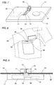
- FIG. 10 to 12 show another preferred embodiment of the present invention in which a case 11A of the transmitter 10A is detachable to a sleeve of the garment 30 by means of snap buttons which are normally utilized in association with clothing. That is, the snap button is made of conductive material and composed of a socket 81 and a ball 82.
- a ground electrode 31A and a signal electrode 32A are provided at the sleeve of the garment 30 for direct coupling with the electric circuitry of the transmitter 10A.
- Other structures are identical to the above embodiment and therefore no duplicated explanation is made herein.
- the case 11A is in the form of a water-tight thin plate accommodating the electric circuitry 28A of the transmitter 10A and the battery 12A.
- the case 11 A is provided with a pair of the sockets 81 which are internally connected to the electrical circuitry of the transmitter 10A , while the electrodes 31A and 32A are provided respectively with the balls 82.
- each electrode is made of conductive threads woven and sewed on or into the sleeve to form an annular band surrounding the sleeve in close proximity to the skin of the user wearing the garment for establishing a reliable electrical connection to the human body.
- the balls 82 are sewed directly on the electrodes by use of the conductive threads or press-fitted into the electrode, thereby eliminating the leads extending otherwise by a certain distance along the garment from the electrodes.
- the balls may be provided on the case, or a mixed pair of the ball and socket is provide on the case.
- the ground and signal electrodes 31 and 32 are explained to be formed by the electrically conductive threads, however, the each electrode may be formed as a metal plating deposited on the surface of the garment or deposited on a fabric which is sewed on the garment.
- the garment into which the electrodes are integrated is not limited to the garment like the white gown and may be any other kinds of the clothing that is constantly worn by the user who is in access to the verified system. Therefore, the clothing may include an armband and wristband integrating the electrodes to which the case of the transmitter can be made electrically and physically detachable by use of the above described snap buttons.
- the illustrated embodiments show only one application where both of the electrodes are kept in close facing relation with the skin of the user so that both of the electrodes are in direct electrical connection to the user's body, however, it is equally possible that one of the electrodes is in direct facing relation, i.e., electrical connection to the user's body, while the other of the electrodes is arranged to face away from the user's skin for capacitive connection to the receiver through the air.
- the illustrated embodiment is arranged to verify the data, i.e., the user's ID at the computer 60
- the receiver 40 may be arranged to equip the processor and the data memory so as to have a function of verifying the data from the transmitter, and providing a verified output to an associated device for permitting the access or a required control of the device, for example, permitting an entry of the user into a restricted area.
Abstract
Description
- The present invention relates to a data transmission system using a human body as a signal path, and more particularly to a system composed of a wearable transmitter, a receiver adapted to be connected to an associated equipment which utilize data transmitted from the transmitter, and a garment integrally holding two electrodes for passing the data through the human body.
- EP application No. 00113564.9 discloses a data transmission system using the human body as a signal path. The system includes a portable transmitter in the form of a wrist watch to be worn on a user, and a signal receiver. The transmitter has a pair of electrodes on the back of the wrist watch for direct contact with the skin of the user. One electrode acts as a signal electrode which is connected through a portion of the user's body to a touch electrode of the signal receiver, while the other electrode acts as a ground electrode which is coupled through the other portion of the user's body to a circuit ground of the signal receiver to complete a signal path through the user's body for data transmission from the wrist watch to the signal receiver. When using this system used for a verified access to a place or database, however, the user is always required to keep in mind to carry the dedicated wrist watch having the electrodes. This may be sometimes inconvenient and even troublesome for the user who has his own wrist watch.
- In view of the above inconvenience, the present invention has been achieved to provide a data transmission system which is capable of assuring successful data transmission without requiring a special attention to the user. The system in accordance with the present invention comprises a transmitter adapted to be carried by the user and a receiver adapted to be connected to an associated equipment which utilizes data transmitted from the transmitter. The transmitter has a ground electrode to be placed in close proximity to the human body, a signal electrode to be placed also in close proximity to the human body in a spatially spaced relation from the ground electrode, a data memory storing first data, a first modulator for converting the first data into a first modulated voltage signal, and a first signal transmitter which applies the first modulated voltage signal across the signal electrode and the ground electrode. The receiver includes a circuit ground adapted to be connected to the ground, a touch electrode adapted for direct contact with a portion of the human body carrying the transmitter, a signal detector connected across the signal electrode and the circuit ground to detect the first modulated voltage signal, and a demodulator which converts the first modulated voltage signal back into the first data. The characterizing feature of the present invention resides in that the system includes a garment which is adapted to be worn by a user and integrates the ground and signal electrodes in such a manner that at least one of the electrodes is kept in a closely facing relation to the skin of the user, thereby establishing an electrical path extending through a portion of the human body for signal transmission from the transmitter to the receiver. With the integration of the two electrodes into the garment, the user wearing the garment as an everyday clothes or uniform such as a white gown can be easy and convenient to carry the transmitter for successful transmission of the data to the receiver.
- Preferably, each of the ground and signal electrodes is formed by a plurality of electrically conductive threads and is sewed to be integrated into the garment. Thus, the electrodes can be easily integrated into the garment and cannot sacrifice comfortableness of the garment. Each electrode made of the electrically conductive threads can be woven into a fabric so as to be lined on the garment. Alternatively, the electrode of the conductive threads can be woven into an indispensable part of the garment. With the use of the electrical conductive threads, the garment provided with the resulting electrodes can be washed like ordinary clothes, which enhances availability of the system.
- The ground electrode is preferred to be located on the garment closer to the foot of the user than the signal electrode for establishing a consistent electrical path through the human body. That is, the electrical path is composed of a first fraction path extending from the ground electrode down to the foot of the user and through the ground to the circuit ground of the receiver, and a second fraction path extending from the signal electrode towards and through a finger of the user to the touch electrode of the receiver without interfering the first fraction path, thereby assuring efficient and reliable data transmission.
- In a preferred embodiment where both of the ground and signal electrodes are held on the garment so as to come into a closely facing relation with the skin of the user, the transmitter has a case which accommodates an electrical circuitry realizing the first modulator and the first signal transmitter, and which is formed as a separate article from the electrodes. The case is provided with terminals for electrically connecting the circuitry with the ground and signal electrodes. In this connection, the garment is additionally provided with a ground lead and a signal lead which extend respectively from the ground and signal electrodes for connection with the terminals of the case. Both of the ground and signal leads are formed by a strand of the electrically conductive threads and are sewed on the garment. Thus, the leads can be also easily and consistently integrated into the garment to retain comfortableness of the garment.
- A coupling member is included in the system to make the case detachable from the garment and at the same time make the electrical circuitry detachable from the electrodes, i.e., the corresponding leads. The coupling member may be realized by a spring-loaded clip which is pivotally supported to the case so as to be movable between a pinching position and a release position. The clip is formed with the terminals which are electrically isolated from each other for connection respectively with the ground and signal leads at the pinching position.
- Instead of the clip, the coupling member may comprise a pair of first fasteners each composed of one of a socket and a ball forming a snap button for mounting the case to the garment, and a pair of second fasteners each composed of the other of the socket and the ball. The first fasteners are fixed on the case and connected across the first signal transmitter of the circuitry, while the second fasteners are fixed on the garment and are permanently connected to respectively to the ground and signal electrodes. When using the snap button to make the case detachable from the garment, the second fasteners are preferably held in direct contact with the ground and signal electrodes, respectively formed of the electrically conductive threads, thereby substantially eliminating the leads from the garment. In this connection, the ground and signal electrodes may be in the form of annular bands provided inside of a sleeve of the garment in a spaced relation from each other along the length of the sleeve.
- Preferably, the case is made water-tight for sealing the electric circuitry so that the garment can be washed like ordinal clothes even with the case. Further, the case may be in the form of a plate which encapsulate the circuitry and a battery energizing the circuitry. Thus, the plate can be utilized also as a nameplate as is usual with the white gown worn by a physician, nurse, and a laboratory worker.
- These and still other objects and advantageous features will become more apparent from the following description of the preferred embodiments when taken in conjunction with the attached drawings.
-
- FIG. 1 is a schematic view illustrating a basic concept of a data transmission system in accordance with the present invention;
- FIG. 2 is a block diagram of a wearable transmitter utilized in the above system;
- FIG. 3 is a block diagram of an associated receiver utilized in the above system;
- FIGS. 4 and 5 are front and rear views of a garment utilized in the above system to integrate a ground electrode and a signal electrode;
- FIG. 6 is a perspective view showing one typical application of the above system;
- FIG. 7 is a rear perspective view of a case in the form of a nameplate accommodating an electric circuitry of the transmitter and detachable to the garment;
- FIG. 8 is a perspective view of the case and a portion of the garment to which the case is attached;
- FIG. 9 is a view showing the nameplate as attached to the garment;
- FIG. 10 is schematic view illustrating another embodiment of the system;
- FIG. 11 is an exploded perspective view showing ground and signal electrodes integrated into a sleeve of the garment and a transmitter case detachable thereto; and
- FIG. 12 is a side view of the transmitter case.
-
- Referring first to FIG. 1, there is shown a principle of a data transmission system using a human body as a signal transmission path. The system includes a
wearable transmitter 10 adapted to be worn on the human body, and areceiver 40 adapted to be connected to an equipment such as apersonal computer 60 which utilizes data transmitted from the transmitter for controlled operation of thecomputer 60, for example, a verified log-in of the user. Thetransmitter 10 is connected to aground electrode 31 and asignal electrode 32 which are integrated into agarment 30 worn by a user in close proximity to the skin of the user. When the user carrying thetransmitter 10 touches atouch electrode 41 of thereceiver 40, a signal path is established which extends from thesignal electrode 32 through a portion of the user's body, thetouch electrode 41, an internal circuit of thereceiver 40, acircuit ground 49 of thereceiver 40, the ground G, the other portion of the user's body, theground electrode 31 and an internal circuit of thetransmitter 10. The signal path extending through the human body is indicated by dotted lines. Thus, a voltage signal applied across theelectrodes receiver 40 when the user touches thetouch electrode 41. In FIG. 1, the circuit ground of thereceiver 40 is connected to the ground G through aground line 64 common to thecomputer 60 for the sake of simplicity. However, the circuit ground may be capacitively connected to the ground G or even capacitively connected directly to the major portion of the user's body for establishing the signal path. - As shown in FIG. 2, the
transmitter 10 includes an electric circuitry and abattery 12 which are accommodated within acase 11. The circuitry includes adata memory 13 storing data to be transmitted, acontroller 14, amodulator 15 modulating the data into a modulated voltage signal, asignal transmitter 16 applying the modulated voltage signal across thesignal electrode 32 and theground electrode 31 on thegarment 30. Also included in the circuitry is asignal detector 20 which is connected to detect a start signal transmitted from thereceiver 40 through thesignal electrode 32. The start signal is received across thesignal electrode 32 and acircuit ground 19. Thecircuit ground 19 may be connected to theground electrode 31. Only thecontroller 14 and thesignal detector 20 are constantly energized by thebattery 12 to be ready for detecting the start signal from thereceiver 40. In the non-operative condition where thetransmitter 10 is not transmitting the data, thecontroller 14 is kept in a sleep mode of consuming less electric current from thebattery 12. When the start signal is received as a consequence of the user touching thetouch electrode 41, thesignal detector 20 wakes up thecontroller 14 which in turn energizes thedata memory 13, themodulator 15, and thesignal transmitter 16 to apply the modulated voltage signal across thesignal electrode 32 and theground electrode 31 for initiating the data transmission. Thecontroller 14 incorporates a timer which starts upon detection of the start signal to provide a predetermined time during which the data is transmitted. After the elapse of the predetermined time, thecontroller 14 responds to deenergize themodulator 15, thesignal transmitter 16 and thedata memory 13. For this purpose, thecontroller 14 includes power switches 21 and 22 which are actuated by thesignal detector 20 and the timer to selectively energize and deenergize themodulator 15, thesignal transmitter 16 and thedata memory 13. Dotted lines in FIG. 2 show power supply lines from thebattery 12. Thus, after transmitting the data, thecontroller 14 goes back into the sleep mode of consuming less current or energy but being kept ready to detect of the start signal for another data transmission. Thetransmitter 10 optionally includes adisplay 24 for visual indication of the data stored in thedata memory 15. - As shown in FIG. 3, the
receiver 40 includes various circuits connected to thetouch electrode 41 on the exterior of a housing of the receiver. The circuits are energized by apower source 61 provided in thecomputer 60 to which thereceiver 40 is attached. The circuits are commonly connected to acircuit ground 49 which is in turn connected to aground terminal 69 of the computer for connection with the ground. The circuits include atouch sensor 42 which is connected to thetouch electrode 41 to give a touch signal when thetouch electrode 41 is touched by the user's body. Also included in the circuits are astart signal generator 43, asignal detector 44, ademodulator 45, and acontroller 46 which controls the operations of the circuits. Thesignal transmitter 43 applies the start signal to thetouch electrode 41 in response to the touch signal. Thesignal detector 44 detects the modulated voltage signal which is transmitted from thetransmitter 10 and received across thetouch electrode 41 and thecircuit ground 49. The modulated voltage signal thus detected is demodulated at thedemodulator 45 to derive the first data which is then fed to thecomputer 60 to be processed thereat. For example, the first data includes a user's identification code which is verified at aprocessor 62 of the computer with reference to various codes assigned to different users and stored in adata memory 63. When the user's ID is verified as a correct one, the computer completes the log-in sequence to permit the access by the user. - Under the non-operating condition where the
touch electrode 41 is not touched by the human body, only thecontroller 46 and thetouch sensor 42 are energized to be ready for detection of the touching. Upon thetouch electrode 41 being touched, thetouch sensor 42 gives the touch signal to thecontroller 46 which responds to closeswitches signal transmitter 43, thesignal detector 44, and thedemodulator 45, thereby generating the start signal and making the circuits ready for receiving the data from thetransmitter 10. Thecontroller 46 also includes a timer which starts, upon receiving the touch signal, to provide a predetermined time interval during which the data transmission from thefirst transceiver 10 is expected to complete. After the elapse of the predetermined time interval, thecontroller 46 responds to open theswitches signal transmitter 43, thesignal detector 44, and thedemodulator 45. Thus, thereceiver 40 is kept in a sleep mode of consuming less electricity until thetouch electrode 41 is touched. Dotted lines in FIG. 3 show power supply lines. Thereceiver 40 further includes aninterface 54 in the form of the USB for transferring the data to thecomputer 60 as well as for receiving the power from apower supply 61. - Further, the
transmitter 10 and thereceiver 40 are designed to effect a bilateral data transmission therebetween. For this purpose, thetransmitter 10 additionally includes ademodulator 25 for demodulating data transmitted from thereceiver 40 and that thereceiver 40 additionally includes amodulator 47 for modulating the data to be transmitted from thereceiver 40. Themodulator 47 of gives a modulated voltage signal indicative of the data to be transmitted to thetransmitter 10. Thesignal transmitter 43 of thereceiver 40 is responsible for applying the modulated voltage signal to thetouch electrode 41 for data transmission back to thetransmitter 10. - In operation, when the user touches the
touch electrode 41 of thereceiver 40, thetouch sensor 42 provides a touch signal in response to which thecontroller 46 energizes themodulator 47, thesignal transmitter 43, thedemodulator 45, and thesignal detector 44. At first, thecontroller 46 retrieves the data from thedata memory 63 of thecomputer 60 and instructs to give and apply the modulated voltage signal indicative of the data. In response to the voltage signal from thereceiver 40, thecontroller 14 of thetransmitter 10 activates thedata memory 13 and performs a suitable processing of the data from thedata memory 13 in consideration of the data received from thereceiver 40. Thecontroller 14 updates the data of thedata memory 13 depending upon the result of the processing. Thereafter, thecontroller 14 activates themodulator 15 and thesignal transmitter 16 so as to transmit the modulated voltage signal indicative of the updated data to thereceiver 40 through theelectrodes receiver 40 is converted into the data which is utilized by thecontroller 46 for a controlled operation of the computer or passed to another equipment to be processed thereat for a specific operation of the equipment. In this manner, the two-way data transmission is made between the transmitter and the receiver in a half-duplex manner. Depending upon a specific application to which the system is applied, the system may be designed to have more than one data transmission cycles in which the one-way data transmission from either of the transmitter and the receiver repeats twice or more. In such case, the data in thedata memory 13 of thetransmitter 10 is modified or updated by the data transmitted from thereceiver 40. - Also, for minimizing energy consumption, the
transmitter 10 is kept in the sleep mode until the modulated voltage signal is received from thereceiver 40, and comes back again in the sleep mode after the data transmission between the transmitter and the receiver is completed. In other words, thedata memory 13, themodulator 15, thesignal transmitter 16, and thedemodulator 21 are energized by closure of theswitches touch electrode 41 is touched by the human body, and come back to the sleep mode after the data transmission between the first and second transceivers are completed. Thus, thesignal transmitter 43, themodulator 47, thesignal detector 44, and thedemodulator 45 are energized by closure ofswitches - As shown in FIGS. 1, 4, and 5, the
garment 30 to which theelectrodes garment 30 is not limited to the white gown and may take various types of the clothes such as a uniform for an office, factory, school, and the like organization or group. Each of theground electrode 31 and thesignal electrode 32 is in the form of a fabric made by electrically conductive threads and is sewed on the inner surface of thegarment 30 with thesignal electrode 32 disposed at the shoulders of thegarment 30 and with theground electrode 31 disposed around the lower part of the garment corresponding to a hip and buttocks of the user, as shown in FIGS. 4 and 5. Instead of being lined on the garment, the electrodes may be woven into the garment as indispensable parts thereof. The above selected location of theelectrodes computer 60 while sitting on a chair as shown in FIG. 6. In this condition, theground electrode 31 receives a counter force from the seat of the chair to be pressed against the buttocks of the user, while thesignal electrode 32 is pressed against the shoulders of the user with the help of weight of the garment for reliable electrical connection of the electrodes to the human body. It is noted in this connection that theground electrode 31 is located closer to the foot of the user than thesignal electrode 32 along the signal path extending through the human body so that the path extending from thesignal electrode 32 toward the finger of the user can be substantially free from, i.e., cannot be substantially interfered with the path extending from theground electrode 31 to the foot of the user for reliable signal transmission between thetransmitter 10 and thereceiver 40. - As shown in FIG. 7, the
case 11 of thetransmitter 10 is formed into a nameplate which is made water-tight and accommodates therein theelectric circuitry 28 forming the various functional circuits and elements as shown in FIG. 2, and thebattery 12 energizing the circuits. Thecase 11 is provided with a spring-loadedclip 70 so as to be detachable to the garment, for example, at a breast pocket. Theclip 70 is pivotally supported at its one end to the case so as to be movable between a pinching position and a release position. Theclip 70 includes a pair ofconductive terminals signal transmitter 16 and which are isolated by adielectric strip 73. As shown in FIGS. 8 and 9, when thecase 11 is attached to the garment, i.e., the breast pocket, theterminals pads individual electrodes leads garment 30. - FIG. 10 to 12 show another preferred embodiment of the present invention in which a
case 11A of thetransmitter 10A is detachable to a sleeve of thegarment 30 by means of snap buttons which are normally utilized in association with clothing. That is, the snap button is made of conductive material and composed of asocket 81 and aball 82. In this connection, aground electrode 31A and asignal electrode 32A are provided at the sleeve of thegarment 30 for direct coupling with the electric circuitry of thetransmitter 10A. Other structures are identical to the above embodiment and therefore no duplicated explanation is made herein. Thecase 11A is in the form of a water-tight thin plate accommodating theelectric circuitry 28A of thetransmitter 10A and thebattery 12A. Thecase 11 A is provided with a pair of thesockets 81 which are internally connected to the electrical circuitry of thetransmitter 10A, while theelectrodes balls 82. As in the previous embodiment, each electrode is made of conductive threads woven and sewed on or into the sleeve to form an annular band surrounding the sleeve in close proximity to the skin of the user wearing the garment for establishing a reliable electrical connection to the human body. In this embodiment, theballs 82 are sewed directly on the electrodes by use of the conductive threads or press-fitted into the electrode, thereby eliminating the leads extending otherwise by a certain distance along the garment from the electrodes. Alternatively, the balls may be provided on the case, or a mixed pair of the ball and socket is provide on the case. - In the illustrated embodiments, the ground and
signal electrodes - Further, the illustrated embodiments show only one application where both of the electrodes are kept in close facing relation with the skin of the user so that both of the electrodes are in direct electrical connection to the user's body, however, it is equally possible that one of the electrodes is in direct facing relation, i.e., electrical connection to the user's body, while the other of the electrodes is arranged to face away from the user's skin for capacitive connection to the receiver through the air.
- Still further, although the illustrated embodiment is arranged to verify the data, i.e., the user's ID at the
computer 60, thereceiver 40 may be arranged to equip the processor and the data memory so as to have a function of verifying the data from the transmitter, and providing a verified output to an associated device for permitting the access or a required control of the device, for example, permitting an entry of the user into a restricted area. - The features disclosed in the foregoing description, in the claims and/or in the accompanying drawings may, both separately and in any combination thereof, be material for realising the invention in diverse forms thereof.
-
- 10
- transmitter
- 11
- case
- 12
- battery
- 13
- data memory
- 14
- controller
- 15
- modulator
- 16
- signal transmitter
- 19
- circuit ground
- 20
- signal detector
- 21
- switch
- 22
- switch
- 24
- display
- 25
- demodulator
- 28
- electric circuitry
- 30
- garment
- 31
- ground electrode
- 32
- signal electrode
- 33
- lead
- 34
- lead
- 35
- pad
- 36
- pad
- 40
- receiver
- 41
- touch electrode
- 42
- touch sensor
- 43
- signal transmitter
- 44
- signal detector
- 45
- demodulator
- 46
- controller
- 47
- modulator
- 51
- switch
- 52
- switch
- 54
- interface
- 60
- computer
- 61
- power supply
- 62
- processor
- 63
- data memory
- 64
- ground line
- 69
- ground terminal
- 70
- clip
- 71
- terminal
- 72
- terminal
- 73
- dielectric strip
- 81
- socket
- 82
- ball
Claims (20)
- A data transmission system using a human body as a signal transmission path, said system comprising a transmitter (10) adapted to be worn on a human body, and a receiver (40) adapted to be connected to an associated device which utilizes data transmitted from the transmitter,characterized in thatsaid transmitter (10) comprising:a ground electrode (31;31A) which is placed in close proximity to the human body;a signal electrode (32; 32A) which is placed in close proximity to the human body and in a spatially spaced relation from said ground electrode; anda data memory (13) for storing first data to be transmitted;a first modulator (15) for converting said first data into a first modulated voltage signal; anda first signal transmitter (16) which applies the first modulated voltage signal across said signal electrode and said ground electrode; andsaid receiver (40) comprising:a circuit ground (49) adapted to be connected to the ground;a touch electrode (41) adapted for direct contact with a portion of the human body carrying said transmitter;a signal detector (44) connected across said touch electrode and said circuit ground to detect said first modulated voltage signal; anda demodulator (45) for converting said first modulated voltage signal back into said first data;
said system includes a garment (30) which is adapted to be worn by a user and integrates said ground and signal electrodes (31, 32; 31A, 32A) in such a manner that at least one of said ground and signal electrodes is kept in a closely facing relation to the skin of the user, thereby establishing an electrical path extending through a portion of the human body for signal transmission from said transmitter to said receiver. - The data transmission system as set forth in claim 1, wherein both of said ground and signal electrodes (31, 32; 31A, 32A) are carried on the garment so as to come into a closely facing relation with the skin of the user,
- The data transmission system as set forth in claim 1, wherein each of said ground and signal electrodes (31, 32; 31A, 32A) is formed by a plurality of electrically conductive threads and is sewed to be integrated into the garment.
- The data transmission as set forth in claim 3, wherein each of said ground and signal electrodes (31, 32; 31A, 32A) is provided in the form of a fabric made of the electrically conductive threads and is lined on said garment.
- The data transmission system as set forth in claim 3, wherein each of said ground and signal electrodes (31, 32; 31A, 32A) is merged into said garment to constitute an indispensable part of the garment.
- The data transmission system as set forth in claim 1, wherein each of said ground and signal electrodes (31, 32; 31A, 32A) is formed by a metal plating deposited on the surface of the garment.
- The data transmission system as set forth in claim 1, wherein each of said ground and signal electrodes is (31, 32; 31A, 32A) formed by a metal plating deposited on a fabric which is sewed on the garment.
- The data transmission system as set forth in claim 2, wherein said ground electrode (31; 31A) is located on said garment closer to the foot of the user than said signal electrode (32; 32A) along said electrical path extending through the portion of the human body.
- The data transmission system as set forth in claim 8, wherein said signal electrode (32) is located on a shoulder of the garment.
- The data transmission system as set forth in claim 3, whereinboth of said ground and signal electrodes (31, 32; 31A, 32A) are carried on the garment so as to come into a closely facing relation with the skin of the user,said transmitter including a case (11) which accommodates an electrical circuitry (28) realizing said first modulator (15) and said first signal transmitter (16) and which is formed separately from said ground and signal electrodes, said case being provided with terminals (71, 72) for electrically connecting said electric circuitry with said ground and signal electrodes,said garment carrying a ground lead (33) and a signal lead (34) which extend respectively from said ground and signal electrodes for connection with said terminals of said case, each said ground and signal leads being formed by a strand of electrically conductive threads and sewed on said garment.
- The data transmission system as set forth in claim 10, whereinsaid system includes a coupling means (70) by which said case (11) is detachably connected to said garment and at the same time said electrically circuitry is detachably connected to said ground and signal electrodes (31, 32),said coupling means comprising a spring-loaded clip (70) which is pivotally supported to said case to be movable between a pinching position and a release position, said clip being provided with said terminals (71, 72) which are electrically isolated from each other for connection respectively with said ground and signal leads (33, 34) at said pinching position.
- The data transmission system as set forth in claim 2, whereinsaid transmitter (10) including a case (10; 11A) which accommodates an electric circuitry (28) realizing said first modulator (15) and said first signal transmitter (16) and which is formed separately from said ground and signal electrodes, said case being provided with terminals (71, 72; 81) for electrical connecting said electric circuitry respectively with said ground and signal electrodes,said system including a coupling means (70; 81, 82) by which said case is detachably connected to said garment and at the same time said electrical circuitry is connected to said ground and signal electrodes.
- The data transmission system as set forth in claim 12, wherein said coupling means comprises a pair of first fasteners each composed of one of a socket (81) and a ball (82) forming a snap button for mounting said case (11A) to the garment (30), a pair of second fasteners each composed of the other of the socket and ball, said first fasteners (81) being fixed on said case and connected across said first signal transmitter, and said second fasteners (82) being fixed on said garment and permanently connected respectively to said ground and signal electrodes.
- The data transmission system as set forth in claim 13, wherein each of said ground and signal electrodes is formed by a plurality of electrically conductive threads sewed and integrated into the garment, and said second fasteners (82) are held in direct contact with said ground and signal electrodes (31A, 32A), respectively.
- The data transmission system as set forth in claim 14, wherein said ground and signal electrodes (31A, 32A) are respectively in the form of annular bands provided around a sleeve of the garment in a spaced relation from each other along the length of the sleeve.
- The data transmission system as set forth in claim 12, wherein said case (11; 11A) is made water-tight for sealing said electrical circuitry.
- The data transmission system as set forth in claim 1, wherein said case (11; 11A) is provided in the form of a plate which encapsulates an electrical circuitry (28) realizing said first modulator (15) and said first signal transmitter (16), and also a battery (12) energizing the circuitry.
- The data transmission system as set forth in claim 1, whereinsaid receiver (40) additionally includes a second modulator (47) for converting second data into a second modulated voltage signal which is applied between said touch electrode (41) and said circuit ground (49);said transmitter (10) further including a first demodulator (25) for converting said second modulated voltage signal, which is detected through said signal electrode (32; 32A), into said second data.
- The data transmission system as set forth in claim 18, wherein
said transmitter (10) includes a controller (14) which has a function of modifying said first data in accordance with said second data. - The data transmission system as set forth in claim 1, wherein said first data includes a single user's identification code (ID) to be transmitted to said receiver, and said receiver includes an ID memory storing a plurality of assigned user's identification codes respectively given to a plurality of users, and a verifier which verifies the user's ID in comparison with the plurality of the assigned user's identification codes so as to permit an intended action requested by the user wearing said garment.
Applications Claiming Priority (4)
| Application Number | Priority Date | Filing Date | Title |
|---|---|---|---|
| JP2000272984 | 2000-09-08 | ||
| JP2000272984 | 2000-09-08 | ||
| JP2001138479 | 2001-05-09 | ||
| JP2001138479A JP2002157041A (en) | 2000-09-08 | 2001-05-09 | Log-in system for computer |
Publications (3)
| Publication Number | Publication Date |
|---|---|
| EP1187375A4 EP1187375A4 (en) | 2001-12-17 |
| EP1187375A1 true EP1187375A1 (en) | 2002-03-13 |
| EP1187375B1 EP1187375B1 (en) | 2004-03-17 |
Family
ID=26599530
Family Applications (1)
| Application Number | Title | Priority Date | Filing Date |
|---|---|---|---|
| EP01121387A Expired - Lifetime EP1187375B1 (en) | 2000-09-08 | 2001-09-06 | Data transmission system using a human body as a signal transmission path |
Country Status (2)
| Country | Link |
|---|---|
| EP (1) | EP1187375B1 (en) |
| JP (1) | JP2002157041A (en) |
Cited By (9)
| Publication number | Priority date | Publication date | Assignee | Title |
|---|---|---|---|---|
| WO2004010387A1 (en) * | 2002-07-19 | 2004-01-29 | Ident Technology Ag | System and method for accident prevention |
| WO2006096135A1 (en) * | 2005-03-08 | 2006-09-14 | National University Of Singapore | A system and method for monitoring mental fatigue |
| WO2006095286A1 (en) * | 2005-03-08 | 2006-09-14 | Koninklijke Philips Electronics, N.V. | Clipable electronic device with contacts attachable to garment |
| WO2010064162A1 (en) * | 2008-12-05 | 2010-06-10 | Koninklijke Philips Electronics N.V. | User identification based on body-coupled communication |
| WO2011083208A1 (en) * | 2010-01-07 | 2011-07-14 | Kone Corporation | Method and system for giving service requests to a conveyance system |
| EP2413522A1 (en) * | 2009-03-26 | 2012-02-01 | Alps Electric Co., Ltd. | Communication system |
| US8166693B2 (en) | 2006-05-23 | 2012-05-01 | Taser International, Inc. | Systems and methods for conditional use of a product |
| EP2915502A1 (en) * | 2014-03-06 | 2015-09-09 | W & H Dentalwerk Bürmoos GmbH | Medical, in particular dental system |
| EP3386122A4 (en) * | 2015-12-02 | 2019-08-07 | Enfc Inc. | Transmission device, transmission method, and transmission system |
Families Citing this family (1)
| Publication number | Priority date | Publication date | Assignee | Title |
|---|---|---|---|---|
| JP2006268614A (en) | 2005-03-25 | 2006-10-05 | Sony Corp | System, apparatus and method for processing information, program, and recording medium |
Citations (4)
| Publication number | Priority date | Publication date | Assignee | Title |
|---|---|---|---|---|
| US4591854A (en) * | 1982-10-12 | 1986-05-27 | Roundel Electronics Limited | Touch control identification system with portable encoder |
| WO1987003119A1 (en) * | 1985-11-19 | 1987-05-21 | Pal Enterprises | Patient alert locator |
| EP0843425A2 (en) * | 1996-11-14 | 1998-05-20 | International Business Machines Corporation | Electronic communication apparatus using the human body as a transmission medium |
| US5811897A (en) * | 1995-12-20 | 1998-09-22 | Daimler-Benz Ag | Device for the body-bound data transmission between two terminals |
-
2001
- 2001-05-09 JP JP2001138479A patent/JP2002157041A/en active Pending
- 2001-09-06 EP EP01121387A patent/EP1187375B1/en not_active Expired - Lifetime
Patent Citations (4)
| Publication number | Priority date | Publication date | Assignee | Title |
|---|---|---|---|---|
| US4591854A (en) * | 1982-10-12 | 1986-05-27 | Roundel Electronics Limited | Touch control identification system with portable encoder |
| WO1987003119A1 (en) * | 1985-11-19 | 1987-05-21 | Pal Enterprises | Patient alert locator |
| US5811897A (en) * | 1995-12-20 | 1998-09-22 | Daimler-Benz Ag | Device for the body-bound data transmission between two terminals |
| EP0843425A2 (en) * | 1996-11-14 | 1998-05-20 | International Business Machines Corporation | Electronic communication apparatus using the human body as a transmission medium |
Cited By (18)
| Publication number | Priority date | Publication date | Assignee | Title |
|---|---|---|---|---|
| WO2004010387A1 (en) * | 2002-07-19 | 2004-01-29 | Ident Technology Ag | System and method for accident prevention |
| WO2006096135A1 (en) * | 2005-03-08 | 2006-09-14 | National University Of Singapore | A system and method for monitoring mental fatigue |
| WO2006095286A1 (en) * | 2005-03-08 | 2006-09-14 | Koninklijke Philips Electronics, N.V. | Clipable electronic device with contacts attachable to garment |
| US8166693B2 (en) | 2006-05-23 | 2012-05-01 | Taser International, Inc. | Systems and methods for conditional use of a product |
| US8866760B2 (en) | 2008-12-05 | 2014-10-21 | Koninklijke Philips N.V. | User identification based on body-coupled communication |
| WO2010064162A1 (en) * | 2008-12-05 | 2010-06-10 | Koninklijke Philips Electronics N.V. | User identification based on body-coupled communication |
| CN102239655A (en) * | 2008-12-05 | 2011-11-09 | 皇家飞利浦电子股份有限公司 | User identification based on body-coupled communication |
| EP2413522A4 (en) * | 2009-03-26 | 2015-03-25 | Alps Electric Co Ltd | Communication system |
| EP2413522A1 (en) * | 2009-03-26 | 2012-02-01 | Alps Electric Co., Ltd. | Communication system |
| US8544612B2 (en) | 2010-01-07 | 2013-10-01 | Kone Corporation | Methods and systems for providing service requests to conveyance systems |
| WO2011083208A1 (en) * | 2010-01-07 | 2011-07-14 | Kone Corporation | Method and system for giving service requests to a conveyance system |
| EP2915502A1 (en) * | 2014-03-06 | 2015-09-09 | W & H Dentalwerk Bürmoos GmbH | Medical, in particular dental system |
| WO2015132369A1 (en) * | 2014-03-06 | 2015-09-11 | W & H Dentalwerk Bürmoos GmbH | Dental system |
| AU2015226105B2 (en) * | 2014-03-06 | 2017-03-30 | W & H Dentalwerk Burmoos Gmbh | Dental system |
| EP3597138A1 (en) * | 2014-03-06 | 2020-01-22 | W & H Dentalwerk Bürmoos GmbH | Medical, in particular dental system |
| US10610309B2 (en) | 2014-03-06 | 2020-04-07 | W&H Dentalwerk Bürmoos GmbH | Dental system |
| US11426244B2 (en) | 2014-03-06 | 2022-08-30 | W&H Dentalwerk Bürmoos GmbH | Dental system |
| EP3386122A4 (en) * | 2015-12-02 | 2019-08-07 | Enfc Inc. | Transmission device, transmission method, and transmission system |
Also Published As
| Publication number | Publication date |
|---|---|
| EP1187375B1 (en) | 2004-03-17 |
| EP1187375A4 (en) | 2001-12-17 |
| JP2002157041A (en) | 2002-05-31 |
Similar Documents
| Publication | Publication Date | Title |
|---|---|---|
| US6864780B2 (en) | Data transmission system using a human body as a signal transmission path | |
| US10148118B2 (en) | Garment device and system having wireless charging function, and charging method using the same | |
| US9008794B2 (en) | Sensor device for treatment and remote monitoring of vital biological parameters | |
| EP1187375B1 (en) | Data transmission system using a human body as a signal transmission path | |
| US20170060298A1 (en) | Smart Interaction Device | |
| US20080114218A1 (en) | Condition improvement advisor | |
| JP2000200315A5 (en) | ||
| TWM546128U (en) | Wearable equipment | |
| EP1058920B1 (en) | Emergency signaling or diagnostic device | |
| US8467861B2 (en) | Accessory for performance-monitoring device | |
| JP2010109801A (en) | Communication device | |
| JP3124788U (en) | Glove-type physiological measurement device | |
| CN111387961A (en) | Exempt from to charge waterproof ring formula body temperature pulse oximetry | |
| CN109276427A (en) | Intelligent massaging clothing | |
| CN113329653A (en) | A textile element such as a garment | |
| CN212346511U (en) | Exempt from to charge waterproof ring formula body temperature pulse oximetry | |
| US20180121779A1 (en) | Sensor device | |
| JP2003008453A (en) | Terminal to be detected and footwear | |
| CN113110228B (en) | Intelligent work card rope and intelligent work card | |
| GB2585729A (en) | Electronics module for a wearable article | |
| CN205885423U (en) | A sleeve area and electrosphygmomanometer for electrosphygmomanometer | |
| GB2592900A (en) | Electronics module for a wearable article | |
| TWM548453U (en) | Smart clothing | |
| CN209575228U (en) | A kind of electric massage glove | |
| CN214342315U (en) | Intelligent posture corrector and wearable equipment |
Legal Events
| Date | Code | Title | Description |
|---|---|---|---|
| PUAI | Public reference made under article 153(3) epc to a published international application that has entered the european phase |
Free format text: ORIGINAL CODE: 0009012 |
|
| AK | Designated contracting states |
Kind code of ref document: A1 Designated state(s): DE FR GB IT Kind code of ref document: A1 Designated state(s): AT BE CH CY DE DK ES FI FR GB GR IE IT LI LU MC NL PT SE TR |
|
| AX | Request for extension of the european patent |
Free format text: AL;LT;LV;MK;RO;SI |
|
| 17P | Request for examination filed |
Effective date: 20020510 |
|
| 17Q | First examination report despatched |
Effective date: 20020716 |
|
| AKX | Designation fees paid |
Free format text: DE FR GB IT |
|
| GRAH | Despatch of communication of intention to grant a patent |
Free format text: ORIGINAL CODE: EPIDOS IGRA |
|
| GRAH | Despatch of communication of intention to grant a patent |
Free format text: ORIGINAL CODE: EPIDOS IGRA |
|
| GRAH | Despatch of communication of intention to grant a patent |
Free format text: ORIGINAL CODE: EPIDOS IGRA |
|
| GRAH | Despatch of communication of intention to grant a patent |
Free format text: ORIGINAL CODE: EPIDOS IGRA |
|
| GRAA | (expected) grant |
Free format text: ORIGINAL CODE: 0009210 |
|
| AK | Designated contracting states |
Kind code of ref document: B1 Designated state(s): DE FR GB IT |
|
| REG | Reference to a national code |
Ref country code: GB Ref legal event code: FG4D |
|
| REG | Reference to a national code |
Ref country code: IE Ref legal event code: FG4D |
|
| REF | Corresponds to: |
Ref document number: 60102331 Country of ref document: DE Date of ref document: 20040422 Kind code of ref document: P |
|
| ET | Fr: translation filed | ||
| PLBE | No opposition filed within time limit |
Free format text: ORIGINAL CODE: 0009261 |
|
| STAA | Information on the status of an ep patent application or granted ep patent |
Free format text: STATUS: NO OPPOSITION FILED WITHIN TIME LIMIT |
|
| 26N | No opposition filed |
Effective date: 20041220 |
|
| REG | Reference to a national code |
Ref country code: IE Ref legal event code: MM4A |
|
| PGFP | Annual fee paid to national office [announced via postgrant information from national office to epo] |
Ref country code: DE Payment date: 20110831 Year of fee payment: 11 Ref country code: FR Payment date: 20110922 Year of fee payment: 11 Ref country code: GB Payment date: 20110831 Year of fee payment: 11 |
|
| PGFP | Annual fee paid to national office [announced via postgrant information from national office to epo] |
Ref country code: IT Payment date: 20110914 Year of fee payment: 11 |
|
| GBPC | Gb: european patent ceased through non-payment of renewal fee |
Effective date: 20120906 |
|
| REG | Reference to a national code |
Ref country code: FR Ref legal event code: ST Effective date: 20130531 |
|
| PG25 | Lapsed in a contracting state [announced via postgrant information from national office to epo] |
Ref country code: GB Free format text: LAPSE BECAUSE OF NON-PAYMENT OF DUE FEES Effective date: 20120906 Ref country code: DE Free format text: LAPSE BECAUSE OF NON-PAYMENT OF DUE FEES Effective date: 20130403 |
|
| PG25 | Lapsed in a contracting state [announced via postgrant information from national office to epo] |
Ref country code: FR Free format text: LAPSE BECAUSE OF NON-PAYMENT OF DUE FEES Effective date: 20121001 Ref country code: IT Free format text: LAPSE BECAUSE OF NON-PAYMENT OF DUE FEES Effective date: 20120906 |
|
| REG | Reference to a national code |
Ref country code: DE Ref legal event code: R119 Ref document number: 60102331 Country of ref document: DE Effective date: 20130403 |