EP1187568B1 - Multi-axial bone anchor system - Google Patents
Multi-axial bone anchor system Download PDFInfo
- Publication number
- EP1187568B1 EP1187568B1 EP00922104A EP00922104A EP1187568B1 EP 1187568 B1 EP1187568 B1 EP 1187568B1 EP 00922104 A EP00922104 A EP 00922104A EP 00922104 A EP00922104 A EP 00922104A EP 1187568 B1 EP1187568 B1 EP 1187568B1
- Authority
- EP
- European Patent Office
- Prior art keywords
- washer
- implant
- stabilizer
- bone
- elongated member
- Prior art date
- Legal status (The legal status is an assumption and is not a legal conclusion. Google has not performed a legal analysis and makes no representation as to the accuracy of the status listed.)
- Expired - Lifetime
Links
Images


Classifications
-
- A—HUMAN NECESSITIES
- A61—MEDICAL OR VETERINARY SCIENCE; HYGIENE
- A61B—DIAGNOSIS; SURGERY; IDENTIFICATION
- A61B17/00—Surgical instruments, devices or methods, e.g. tourniquets
- A61B17/56—Surgical instruments or methods for treatment of bones or joints; Devices specially adapted therefor
- A61B17/58—Surgical instruments or methods for treatment of bones or joints; Devices specially adapted therefor for osteosynthesis, e.g. bone plates, screws, setting implements or the like
- A61B17/68—Internal fixation devices, including fasteners and spinal fixators, even if a part thereof projects from the skin
- A61B17/70—Spinal positioners or stabilisers ; Bone stabilisers comprising fluid filler in an implant
- A61B17/7058—Plates mounted on top of bone anchor heads or shoulders
-
- A—HUMAN NECESSITIES
- A61—MEDICAL OR VETERINARY SCIENCE; HYGIENE
- A61B—DIAGNOSIS; SURGERY; IDENTIFICATION
- A61B17/00—Surgical instruments, devices or methods, e.g. tourniquets
- A61B17/56—Surgical instruments or methods for treatment of bones or joints; Devices specially adapted therefor
- A61B17/58—Surgical instruments or methods for treatment of bones or joints; Devices specially adapted therefor for osteosynthesis, e.g. bone plates, screws, setting implements or the like
- A61B17/68—Internal fixation devices, including fasteners and spinal fixators, even if a part thereof projects from the skin
- A61B17/70—Spinal positioners or stabilisers ; Bone stabilisers comprising fluid filler in an implant
- A61B17/7001—Screws or hooks combined with longitudinal elements which do not contact vertebrae
- A61B17/7002—Longitudinal elements, e.g. rods
- A61B17/7004—Longitudinal elements, e.g. rods with a cross-section which varies along its length
- A61B17/7007—Parts of the longitudinal elements, e.g. their ends, being specially adapted to fit around the screw or hook heads
-
- A—HUMAN NECESSITIES
- A61—MEDICAL OR VETERINARY SCIENCE; HYGIENE
- A61B—DIAGNOSIS; SURGERY; IDENTIFICATION
- A61B17/00—Surgical instruments, devices or methods, e.g. tourniquets
- A61B17/56—Surgical instruments or methods for treatment of bones or joints; Devices specially adapted therefor
- A61B17/58—Surgical instruments or methods for treatment of bones or joints; Devices specially adapted therefor for osteosynthesis, e.g. bone plates, screws, setting implements or the like
- A61B17/68—Internal fixation devices, including fasteners and spinal fixators, even if a part thereof projects from the skin
- A61B17/70—Spinal positioners or stabilisers ; Bone stabilisers comprising fluid filler in an implant
- A61B17/7001—Screws or hooks combined with longitudinal elements which do not contact vertebrae
- A61B17/7002—Longitudinal elements, e.g. rods
- A61B17/701—Longitudinal elements with a non-circular, e.g. rectangular, cross-section
-
- A—HUMAN NECESSITIES
- A61—MEDICAL OR VETERINARY SCIENCE; HYGIENE
- A61B—DIAGNOSIS; SURGERY; IDENTIFICATION
- A61B17/00—Surgical instruments, devices or methods, e.g. tourniquets
- A61B17/56—Surgical instruments or methods for treatment of bones or joints; Devices specially adapted therefor
- A61B17/58—Surgical instruments or methods for treatment of bones or joints; Devices specially adapted therefor for osteosynthesis, e.g. bone plates, screws, setting implements or the like
- A61B17/68—Internal fixation devices, including fasteners and spinal fixators, even if a part thereof projects from the skin
- A61B17/70—Spinal positioners or stabilisers ; Bone stabilisers comprising fluid filler in an implant
- A61B17/7001—Screws or hooks combined with longitudinal elements which do not contact vertebrae
- A61B17/7002—Longitudinal elements, e.g. rods
- A61B17/7011—Longitudinal element being non-straight, e.g. curved, angled or branched
-
- A—HUMAN NECESSITIES
- A61—MEDICAL OR VETERINARY SCIENCE; HYGIENE
- A61B—DIAGNOSIS; SURGERY; IDENTIFICATION
- A61B17/00—Surgical instruments, devices or methods, e.g. tourniquets
- A61B17/56—Surgical instruments or methods for treatment of bones or joints; Devices specially adapted therefor
- A61B17/58—Surgical instruments or methods for treatment of bones or joints; Devices specially adapted therefor for osteosynthesis, e.g. bone plates, screws, setting implements or the like
- A61B17/68—Internal fixation devices, including fasteners and spinal fixators, even if a part thereof projects from the skin
- A61B17/70—Spinal positioners or stabilisers ; Bone stabilisers comprising fluid filler in an implant
- A61B17/7001—Screws or hooks combined with longitudinal elements which do not contact vertebrae
- A61B17/7035—Screws or hooks, wherein a rod-clamping part and a bone-anchoring part can pivot relative to each other
-
- A—HUMAN NECESSITIES
- A61—MEDICAL OR VETERINARY SCIENCE; HYGIENE
- A61B—DIAGNOSIS; SURGERY; IDENTIFICATION
- A61B17/00—Surgical instruments, devices or methods, e.g. tourniquets
- A61B17/56—Surgical instruments or methods for treatment of bones or joints; Devices specially adapted therefor
- A61B17/58—Surgical instruments or methods for treatment of bones or joints; Devices specially adapted therefor for osteosynthesis, e.g. bone plates, screws, setting implements or the like
- A61B17/68—Internal fixation devices, including fasteners and spinal fixators, even if a part thereof projects from the skin
- A61B17/70—Spinal positioners or stabilisers ; Bone stabilisers comprising fluid filler in an implant
- A61B17/7001—Screws or hooks combined with longitudinal elements which do not contact vertebrae
- A61B17/7041—Screws or hooks combined with longitudinal elements which do not contact vertebrae with single longitudinal rod offset laterally from single row of screws or hooks
-
- A—HUMAN NECESSITIES
- A61—MEDICAL OR VETERINARY SCIENCE; HYGIENE
- A61B—DIAGNOSIS; SURGERY; IDENTIFICATION
- A61B17/00—Surgical instruments, devices or methods, e.g. tourniquets
- A61B17/56—Surgical instruments or methods for treatment of bones or joints; Devices specially adapted therefor
- A61B17/58—Surgical instruments or methods for treatment of bones or joints; Devices specially adapted therefor for osteosynthesis, e.g. bone plates, screws, setting implements or the like
- A61B17/68—Internal fixation devices, including fasteners and spinal fixators, even if a part thereof projects from the skin
- A61B17/80—Cortical plates, i.e. bone plates; Instruments for holding or positioning cortical plates, or for compressing bones attached to cortical plates
- A61B17/8033—Cortical plates, i.e. bone plates; Instruments for holding or positioning cortical plates, or for compressing bones attached to cortical plates having indirect contact with screw heads, or having contact with screw heads maintained with the aid of additional components, e.g. nuts, wedges or head covers
- A61B17/8047—Cortical plates, i.e. bone plates; Instruments for holding or positioning cortical plates, or for compressing bones attached to cortical plates having indirect contact with screw heads, or having contact with screw heads maintained with the aid of additional components, e.g. nuts, wedges or head covers wherein the additional element surrounds the screw head in the plate hole
-
- A—HUMAN NECESSITIES
- A61—MEDICAL OR VETERINARY SCIENCE; HYGIENE
- A61B—DIAGNOSIS; SURGERY; IDENTIFICATION
- A61B17/00—Surgical instruments, devices or methods, e.g. tourniquets
- A61B17/56—Surgical instruments or methods for treatment of bones or joints; Devices specially adapted therefor
- A61B17/58—Surgical instruments or methods for treatment of bones or joints; Devices specially adapted therefor for osteosynthesis, e.g. bone plates, screws, setting implements or the like
- A61B17/68—Internal fixation devices, including fasteners and spinal fixators, even if a part thereof projects from the skin
- A61B17/70—Spinal positioners or stabilisers ; Bone stabilisers comprising fluid filler in an implant
- A61B17/7001—Screws or hooks combined with longitudinal elements which do not contact vertebrae
- A61B17/7035—Screws or hooks, wherein a rod-clamping part and a bone-anchoring part can pivot relative to each other
- A61B17/7037—Screws or hooks, wherein a rod-clamping part and a bone-anchoring part can pivot relative to each other wherein pivoting is blocked when the rod is clamped
-
- A—HUMAN NECESSITIES
- A61—MEDICAL OR VETERINARY SCIENCE; HYGIENE
- A61B—DIAGNOSIS; SURGERY; IDENTIFICATION
- A61B17/00—Surgical instruments, devices or methods, e.g. tourniquets
- A61B17/56—Surgical instruments or methods for treatment of bones or joints; Devices specially adapted therefor
- A61B17/58—Surgical instruments or methods for treatment of bones or joints; Devices specially adapted therefor for osteosynthesis, e.g. bone plates, screws, setting implements or the like
- A61B17/68—Internal fixation devices, including fasteners and spinal fixators, even if a part thereof projects from the skin
- A61B17/84—Fasteners therefor or fasteners being internal fixation devices
- A61B17/86—Pins or screws or threaded wires; nuts therefor
- A61B17/8695—Washers
-
- A—HUMAN NECESSITIES
- A61—MEDICAL OR VETERINARY SCIENCE; HYGIENE
- A61B—DIAGNOSIS; SURGERY; IDENTIFICATION
- A61B90/00—Instruments, implements or accessories specially adapted for surgery or diagnosis and not covered by any of the groups A61B1/00 - A61B50/00, e.g. for luxation treatment or for protecting wound edges
- A61B90/03—Automatic limiting or abutting means, e.g. for safety
- A61B2090/037—Automatic limiting or abutting means, e.g. for safety with a frangible part, e.g. by reduced diameter
Definitions
- the present invention concerns orthopedic implants, particularly for the spine or long bones.
- the present invention includes a bone anchor system having multi-axial capabilities, which may be used in conjunction with an orthopedic implant device such as a spinal plate or rod system.
- an elongated member such as a plate or rod
- the vertebrae are positioned in a corrected position as required by the surgeon.
- a plate is placed adjacent to the bone, and bone anchors are employed to secure the plate to the bones.
- Bone screws or bolts are commonly utilized as the bone anchors, and with such anchors placement is accomplished by drilling one or more holes in the bone(s), and threading the anchors into the holes.
- An example of a prior art bone bolt is described in a book by Dr. Cotrel entitled New Instrumentation for Surgery of the Spine . Freund, London 1986.
- This bone bolt is shown in Figure 1.
- An anchor can be threaded into a hole through the plate, or the plate can be placed in position around the anchor after threading into the hole. The anchor and plate are then secured to each other to prevent relative movement. In this way, bones may be held and/or supported in proper alignment for healing.
- a spinal plate system or other similar implant system may have anchors that can be positioned at a number of angles with respect to the plate or other implant.
- Such a feature allows easier placement of implant systems or correction of positioning of an implant system, in that the bone anchors need not be precisely positioned in angular relation with respect to the implant. Rather, with a multi-axial capability, holes can be drilled in a bone at a convenient location and/or angle, for example, and screws can be inserted therein, with the connection between the plate and the anchor being angularly adjustable to provide sufficient force perpendicular to the plate/bone interface to secure the plate.
- the plate system disclosed in U.S. Patent No. 5,613,967 to Engelhardt, et al. discloses a slotted plate through which a bone screw extends.
- the screw includes cancellous threads for placement in bone, an intermediate section with an upper flat portion, and a machine-threaded section.
- the machine-threaded portion fits through the slot In the plate, and the plate abuts the flat portion of the screw or a flat washer imposed between the intermediate portion of the screw and the plate.
- a bracket is placed over the machine-threaded portion of the screw and the slotted plate, and a nut is threaded on the machine-threaded portion of the screw to anchor the screw and plate together.
- This apparatus does not provide the preferred multi-axial capability, as described above.
- U.S. Patent No. 5,084,048 to Jacob et al. discloses apparatus for damping a rod to a bone screw such that the longitudinal planes of the rod and screw are not perpendicular.
- U.S. Patent No. 5,234,431 describes a bone plate arrangement comprising a bone plate defining at least one aperture for receipt of a bone screw supported within a sleeve.
- the angular position of the sleeve, and thereby the bone screw, relative to the bone plate is adjustable.
- Another object of the present invention is to provide a locking mechanism having a plurality of locking locations along a slotted member.
- Still a further object of the present invention is in a preferred embodiment to provide an improved spine system with multi-axial capability and a plurality of locking locations along the systems.
- the present invention provides an orthopedic implant, comprising: a longitudinal member, said longitudinal member having a lower side for facing a bone, an upper side for facing away from a bone, and an aperture through said longitudinal member from said first side to said second side, said longitudinal member further including a longitudinal channel parallel to and between said first and second sides, said channel being substantially perpendicular to said aperture; a stabilizer having an opening therethrough bounded by a conical surface, said stabilizer further having a plurality of laterally extending fingers occupying said channel so that said stabilizer is in one of an infinite number of positions wherein said opening is adjacent to said aperture of said longitudinal member; a fixation member having a first threaded portion for fixing to a bone, a second threaded portion, and a diametrally enlarged portion between said first and second threaded portions, said enlarged portion including a plurality of torque transmission surfaces, and said fixation member extending through said stabilizer and said longitudinal member so that said enlarged portion contacts a portion of said surface bounding said opening of said stabilizer
- implant system 20 includes an elongated member 22, a pair of bone anchor assemblies 24, and a set of supports or stabilizers 26. Differing numbers of any of those elements may be utilized without departing from the scope of this invention.
- a plurality of elongated members 22 can be used in conjunction with each other, or a greater or lesser number of bone anchor assemblies 24 or stabilizers 26 may be used, depending upon the configuration of the elongated member, the medical problem to be addressed, and/or any other factors.
- the present invention contemplates at least one elongated member 22, at least one bone anchor assembly 24 and at least one stabilizer 26.
- Elongated member 22 is in the form of a generally rectangular flat plate and includes a generally longitudinal slot 30 through the thickness of elongated member 22. Within slot 30 is formed a ledge 32. Elongated member 22 also includes a pair of downwardly-extending arms 34 substantially along the length of both sides of elongated member 22. Arms 34 have an inwardly-extending ledge 36 along substantially the entire length of arms 34.
- bone anchor assembly 24 includes a bone bolt 40, an arcuate washer 42, and a break-off nut 44.
- bone bolt 40 includes a bone-engaging portion 46 having cancellous threads 48 thereon.
- Bone bolt 40 also includes a proximal portion 50, which is threaded with machine threads. Between proximal portion 50 and bone-engaging portion 46, there is an intermediate portion 54 which has a rounded configuration. In one specific embodiment, the rounded shoulder has a spherical configuration. The bone bolt is more specifically described below.
- arcuate washer 42 of bone anchor assembly 24 has a generally cylindrical body 60, a rounded or conical head 62, a underside projection 64, and an aperture 66 therethrough.
- Aperture 66 is bounded by inner walls 68 and 70 of washer 42.
- inner wall 68 is conical or tapered such that aperture 66 decreases in diameter from head 62 toward body 60, and inner wall 70 is substantially cylindrical.
- inner wall 70 may not be contiguous with inner wall 68, or walls 68 and 70 may form a single conical surface bounding aperture 66.
- Projection 64 also bounds aperture 66, and in a specific embodiment the outer dimension of projection 64 is approximately square and sized to fit within slot 30 and atop ledge 32 of elongated member 22.
- break-off nut 44 includes an upper break-off portion 76 and a nut portion 78. Both break-off portion 76 and nut portion 78 preferably have a hexagonal outer shape, although any known configuration of the outer portion of break-off portion 76 and nut portion 78 that will allow transmission of torque to one or both can be used with the present invention.
- Break-off nut 44 includes a longitudinal bore 80 therethrough.
- Bore 80 in a specific embodiment, is substantially cylindrical within break-off portion 76, and is substantially cylindrical with a female thread 82 within nut portion 78.
- bore 80 is bounded by a surface 84 for complementary mating with head 62 of arcuate washer 42. While it is contemplated that the surfaces may have any configuration, in a preferred embodiment surface 84 is generally spherical, having a radius larger than the radius of bore 80, and substantially the same radius as the generally spherical head 62 of washer 42.
- Break-off nut 44 also includes a groove or weakened area 86 that allows shearing separation of break-off portion 76 from nut portion 78 after break-off nut 44 has been tightened sufficiently.
- Stabilizer 26 in one embodiment, has an approximately square body 90 with an extending finger portion 92 on opposite sides of stabilizer 26. Stabilizer 26 also has a bore 94 therethrough. Bore 94 is bounded by a conical or tapered wall 96 and substantially cylindrical wall 98. For example, walls 96 and 98 could be non-contiguous or walls 96 and 98 could form a single conical wall bounding bore 94.
- Fingers 92 of stabilizer 26 are shaped and dimensioned to fit within slot 39 of elongated member 22 such that fingers 92 abut ledges 36 and undersurface 37 of elongated member 22.
- stabilizer 26 has a substantially flat bottom surface 97.
- One or more stabilizers 26 may be inserted into slot 39 via an open end of elongated member 22, and until implant system 20 is finally tightened or locked as described below, are slidable along ledges 36 of elongated member 22.
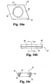
- FIGS. 16a-16c A second embodiment of stabilizer 26' is illustrated in FIGS. 16a-16c.
- Stabilizer 26' is like stabilizer 26 in most respects.
- stabilizer 26' has a body 90' approximately in the shape of a parallelogram.
- Finger portions 92', bore 94' and tapered wall 96' are substantially similar to finger portions 92, bore 94, and tapered wall 96 of stabilizer 26, described and illustrated above.
- tapered wall 96' could be contiguous with or separate from a cylindrical wall which also bounds bore 94'.
- Fingers 92' are shaped in dimension to fit within slot 39 of elongated member 22 such that figures 92' abut ledges 36 and under surface 37 of elongated member 22.
- One or more stabilizers 26' may be inserted into slot 39 via an open end of elongated member 22, and until implant system 20 is finally tightened or locked as described below, are slideable along ledges 36 of elongated member 22.
- the parallelogram configuration of stabilizer 26' allows close center line-to-center line placement of bone bolts or screws when multiple stabilizers 26' are placed adjacent each other, and can reduce the overall thickness of the plate and stabilizer combination required for successful fixation.
- stabilizer 26" is depicted in FIGS. 17a-17c.
- Stabilizer 26" has an approximately rectangular body 90" with extending finger portions 92" on opposite sides of stabilizer 26". Finger portions 92", like finger portions 92 and 92', have flat undersides 93" in one embodiment.
- finger portions 92" can have convexly rounded undersides 93a".
- Stabilizer 26" also has a bore 94" therethrough. Bore 94" is preferably bounded by a conical or tapered wall 96" as discussed above with reference to stabilizers 26 and 26'.
- Stabilizer 26" also includes a rounded bottom surface 97" that substantially surrounds the lower opening of bore 94".
- rounded bottom 97" has a configuration of a portion of a cylinder.
- Fingers 92" of stabilizer 26" are shaped and dimensioned to fit within slot 39 of elongated member 22 such that fingers 92" abut ledges 36 and under surface 37 of elongated member 22.
- One or more stabilizers 26" may be inserted into slot 39 via an open end of elongated member 22, and until implant system 20 is finally tightened or locked as described below, are slideable along ledges 36 of elongated member 22. While the description below specifically names only stabilizer 26, it is understood that stabilizers 26' and 26" are used in the same manner.
- implant system 20 is assembled and used as follows. After the surgeon has drilled one or more holes into a bone or bones, bone bolt 40 is threaded into the hole via cancellous threads on bone-engaging portion 46. After bone bolt 40 is securely affixed to the bone, elongated member 22 including a fitted support or stabilizer 26 is placed over bone bolt 40, so that proximal portion 50 of bone bolt 40 extends through bore 94 of stabilizer 26 and slot 30 of elongated member 22, and such that intermediate portion 54 of bone bolt 40 is within or adjacent to bore 94 of stabilizer 26.
- Washer 42 is placed over proximal portion 50 of bone bolt 40, so that proximal portion 50 extends through aperture 66 of washer 42, and so that underside surface 63 of washer 42 rests on elongated member 22 and underside projection 64 of washer 42 abuts ledge 32 within slot 30 of elongated member 22.
- projection 64 has an approximately square outer configuration
- washer 42 will not be able to rotate about bone bolt 40 when projection 64 is within slot 30 of elongated member 22.
- break-off nut 44 is loosely threaded onto machine thread 52 of bone screw 40, such that surface 84 of nut portion 78 is in adjustable contact with or adjacent to head 62 of washer 42.
- Elongated member can then be adjusted with respect to bone bolt 40, and bone bolt 40 may thereby form one of a variety of angles with respect to elongated member 22.
- the rounded part 56 of intermediate portion 54 of bone bolt 40 is able to articulate within bore 94 and wall portion 96 of stabilizer 26, and inner wall 68 of washer 42 permits proximal portion 50 of bone bolt 40 to correspondingly occupy various angular positions with respect to washer 42 and elongated member 22.
- break-off nut 44 is tightened. As break-off nut 44 is tightened, the torque on break-off portion 76 increases, until break-off portion 76 shears away from nut portion 78 at groove 86.
- groove 86 is above the uppermost portion of bone screw 40 to inhibit irritation to surrounding tissue that might be caused by a protruding post.
- Surface 84 of nut portion 78 being configured similarly or identically to head 62 of washer 42, is able to matingly engage any portion of head 62, enabling secure, tight contact between nut portion 78 and washer 42 regardless of the angle between bone bolt 40 and elongated member 22.
- FIGS: 8 - 13 An alternative embodiment 99 of the present invention is illustrated in FIGS: 8 - 13.
- Elongated member 100 includes a superior end 102, an inferior or caudal end 104, and a longitudinal axis 106 generally extending there between.
- a superior end 102 an inferior or caudal end 104
- a longitudinal axis 106 generally extending there between.
- implanted superior end 102 and inferior end 104 will be oriented as cephalad and caudal ends, respectively.
- Superior end 102 includes a pair of longitudinal slots 108 and 110, which are placed transversely of each other.
- Slot 108 has a configuration very similar to the arrangement of slot 30 in elongated member 22.
- Slot 108 includes a ledge 112 near the upper part of elongated 100, which substantially encircles slot 108 in one specific embodiment. It is contemplated that in another embodiment, slot 108 may include two ledges 112, each running along substantially the entire length of a longitudinal side of slot 108. Preferably, side walls 113, immediately adjacent ledges 112, form a rectangular configuration in the upper portion of slot 108.
- Slot 108 also has a lower ledge 114 that runs substantially along each longitudinal side of slot 108.
- a stabilizer 115 (similar to stabilizer 26 described above) may be placed to bear against ledge 114 as previously discussed with respect to the embodiment of FIG. 2.
- Slot 110 includes a first arcuate or conical surface 116 near the upper surface of elongated member 100, and a second arcuate or conical surface 118 near the lower surface of elongated member 100.
- surfaces 116 and 118 are substantially circular in cross-section.
- the radius of surface 118 is larger than that of surface 116.
- Inferior end 104 of elongated member 100 includes a pair of bores 120 and 122.
- Bore 120 includes side walls 123 and a ledge 124 near the upper surface of elongated member of 100. Side walls 123 define a generally square opening.
- Bore 120 further includes wall 126 which tapers outward in a substantially conical shape from upper to lower surfaces of elongated member 100.
- Bore 122 is a substantially circular bore, having an arcuate surface 128 near the upper surface of elongated member 100. In a preferred embodiment, arcuate surface 128 is spherical.
- elongated member 100 includes a bend along axis 106, separating elongated member 100 into side portions 100a and 100b. Angle A between side portions 100a and 100b is approximately 163 degrees in a preferred embodiment. Other inside angles A of elongated member 100 are contemplated as within the scope of the present invention, as may be required by the configurations of the bones to which elongated member 100 is to be attached or other factors.
- the embodiment of the implant system 99 incorporating elongated member 100 also includes superior or cephalad washer 130 and inferior or caudal washer 132.
- superior washer 130 includes a body portion 134 having an conical or rounded head 136 and an underside 137 having a projection 138, and a lateral extension portion 140.
- head 136 forms a portion of a sphere
- underside projection 138 is flat and in the general form of a square with rounded corners, with the sides of the square of a size slightly less than the width of slot 108 of elongated member 100.
- An aperture 142 extends through body 134 of washer 130.
- An upper wall portion 144 bounds aperture 142, and is tapered from head 136 toward the bottom of washer 130.
- a lower wall portion 146 is generally cylindrical. However, other wall configurations are possible, for example, wall portions 144 and 146 may not be contiguous, or may form a single tapered wall from head 136 to projection 138.
- Lateral extension portion 140 of washer 130 includes a C-clip portion 148, which encloses most of an aperture 150, and downwardly extending flanges 152 and 154.
- C-clip portion 148 has a pair of fingers 149a and 149b. Fingers 149a and 149b have a beveled or substantially conical projection 156 at their respective upper portions.
- the interior opening defined by projection 156 has a slightly smaller diameter than the interior opening defined by walls 153 and 155.
- Flanges 152 and 154 in a specific embodiment, have a length parallel to extension portion 140 slightly smaller than the width of slot 110 of elongated member 100.
- Washer 130 also includes a bend in lateral extension portion 140 that is complementary to the bend along longitudinal axis 106 of elongated member 100. The inside angle B formed by the bend in washer 130 is approximately the same as angle A of elongated member 100.
- washer 130 is fitted into slots 108 and 110 of elongated member 100.
- body portion 134 is placed on slot 108 such that underside 137 of body portion 134 rests on elongated member 100 and projection 138 of body 134 is fitted into slot 108 and rests on ledge 112.
- Flanges 152 and 154 of extension portion 140 are fitted into slot 110.
- washer 130 cannot rotate with respect to elongated member 100 because of the respective fits between (a) projection 138 and the sides of slot 108, (b) flanges 152 and 154 and the sides of slot 110, and (c) the bend in both washer 130 and elongated member 100.
- Washer 132 includes a body 160 having a conical or rounded head 162 and an underside 163 having a substantially square projection 164, and an extension 166.
- Body 160 has an aperture 168 extending therethrough, extending from head 162 to projection 164.
- Aperture 168 is bounded by wall sections 170 and 172.
- wall section 170 is conically tapered from head 162 toward underside projection 164, and wall section 172 is substantially cylindrical.
- Other configurations are possible, however, such as wall sections 170 and 172 being non-contiguous or forming a single conically tapered surface.
- Lateral extension 166 includes a C-clip portion 174, which encircles most of substantially cylindrical aperture 176.
- C-clip portion 174 has a pair of fingers 175a and 175b. Fingers 175b and 175b have a beveled or substantially conical projection 178 at their respective upper portions.
- the opening defined by projection 178 has a diameter slightly smaller than the diameter defined by walls 177 and 179.
- Washer 132 also includes a bend in lateral extension portion 166 that is complementary to the bend along longitudinal axis 106 of elongated member 100. The inside angle C formed by the bend in washer 132 is approximately the same as angle A of elongated member 100.
- Bone bolt 200 includes a bone-engaging portion 202, a proximal portion 204, and an intermediate portion 206.
- bone-engaging portion 202 includes cancellous thread 208, which winds along the length of bone-engaging portion 202 until thread 208 adjoins intermediate portion 206. As the thread pattern nears intermediate portion 206, the root diameter of the thread increases.
- Proximal end 204 includes a shaft portion 210 adjoining intermediate portion 206, a threaded portion 212 proximal of shaft portion 210, and a break-off portion 214 proximal of threaded portion 212.
- break off portion 214 includes torque applying surfaces 216 (for example, hexagonal outer surfaces) to be engaged by a wrench or other nut-driver, and a groove or weakened portion 218. When bolt 200 is secure, further torque applied to torque applying surfaces 216 will cause break-off portion 214 to shear from threaded portion 212 at groove or weakened portion 218.
- Break-off portion 214 is preferably configured so that shear occurs when a relatively light torque is applied, e.g.
- Intermediate portion 206 of bolt 200 is generally rounded, and includes a set of flattened areas 220.
- flattened areas 220 are uniformly spaced around the circumference of intermediate portion 206, in a hexagonal arrangement
- Bone bolt 200a includes the parts of bone bolt 200 identified above, but does not include break-off portion 214.
- Bone bolt 200b includes, in addition to the features of bone bolt 200, a machine threaded section 217 on break-off portion 214.
- Bone bolt 200c includes a longer machine threaded section 217'. Machine threads 217 and 217' may be used to enable the surgeon to shear off break-off portion 214 without losing break-off portion 214 or dropping it into the patient. Further, maching threads 217' have sufficient length to allow reduction of stripped vertebra.
- a cannulated tool having a female thread at its distal end and inner surfaces for torque application could be threaded onto machine threads 217 or 217', and the inner torque surfaces of the tool engaged with break-off portion 214.
- break-off portion 214 is sheared from bolt 200b or 200c, break-off portion 214 is held by the tool by virtue of the interengaged female tool thread and machine threads 217 or 217' of break-off portion 214 of bolt 200b or 200c.
- Bone screw 230 includes a bone engaging portion 232 having cancellous threads 243 thereon, and a head portion 236.
- Head portion 236 includes a lower rounded surface 248 and an upper rounded surface 240.
- surfaces 238 and 240 are separated by a generally cylindrical portion 242.
- Head 236 also includes a tool-engaging recess 244.
- Tool-engaging recess 244 may be of any suitable configuration, including hexagonal, hexalobed, or other configuration.
- Nut 250 includes outer torque application surfaces 252 and an aperture 254 extending longitudinally through nut 250.
- Aperture 254 includes threads 256, which extend from the top of nut 250 toward the bottom of nut 250.
- Aperture 254 widens near the bottom of nut 250, and is bounded by walls 258.
- walls 258 are substantially spherical. However, other configurations are contemplated, such as conical.
- elongated member 100, washers 130 and 132, bolt 200, screw 230 and nut 250 are used in connection with stabilizer 26 or 115 as follows.
- vertebrae long bones, or other bone tissue
- Bolts 200 are threaded into the drilled holes, and when bolts 200 are satisfactorily seated.
- Elongated member 100 is placed over bolts 200, so that proximal portions 204 of bolts 200 extend through slot 108 and bore 120, respectively.
- the proximal portion 204 of one bolt 200 extends through the aperture of stabilizer 26 as well.
- the sides of slot 108 are preferably adjacent to one or more flat portions 220 of one bolt 200.
- Washer 130 is then fitted so that the bolt 200 extending through slot 108 also extends through aperture 142 of washer 130, projection 138 of washer 130 fits within slot 108 and on top of ledge 112 of elongated member 100, and downwardly-extending flanges 152 and 154 fit within slot 110 of elongated member 100. Positioned thusly, washer 130 is not able to rotate about bolt 200 due to the engagement of projection 138 with slot 108 and flanges 152 and 154 with slot 110. Washer 132 is fitted over the bolt 200 within bore 120, so that underside projection 164 of washer 132 rests on ledge 124 within bore 120, and such that aperture 176 of washer 132 and bore 128 of elongated member 100 are roughly aligned.
- Holes may be drilled through bore 128 and slot 110 for screws 230.
- holes for screws 230 may be drilled prior to fitting washers 130 and 132 to elongated member 100, or may be drilled at the same time holes for bolts 200 are drilled.
- a bone screw 230 is threaded into a hole in the bone tissue through aperture 176, washer 132, and bore 128 at inferior end 104 of elongated member 100, and a separate screw 230 is threaded into a separate hole in the bone tissue through aperture 150 of washer 130 and slot 110 at superior end 102 of elongated member 100.
- head 236 comes in contact with C-clip portion 174 of washer 132.
- C-clip portions 174 and 148 can be "tuned” to produce somewhat different sounds and/or to alter the strength of portions 174 and 148 and thereby alter the backing-out or threading force required to pass cylindrical portion 242 of screw 230 backward or forward through portions 174 or 148. This can be accomplished by making C-clip portions 174 and 148, and particularly fingers 175a and 175b and 149a and 149b thereof, thicker or thinner or by placing aperture 176 or 150 eccentrically with respect to washer 132 or 130 respectively.
- nuts 250 are threaded onto threaded portions 212 of bolts 200.
- Surface 258 of one nut 250 is generally configured with a substantially similar shape to head 162 of washer 132
- surface 258 of a second nut 250 is generally configured with a substantially similar shape to head 136 of washer 130.
- respective surfaces 258 are pressed against surfaces 136 and 162 in a close fit.
- upper surfaces 216 may be engaged by a tool during nut tightening to resist rotation of the bolt and after nut tightening torque may be applied to surfaces 216 to shear off the post.
- Elongated member 100 may be positioned with respect to bolts 200 such that the longitudinal axes of bolts 200 are not perpendicular to sides 100a or 100b.
- Wall portion 144 of washer 130 and wall portion 170 of washer 132 are tapered, as noted above, to accommodate the positioning of a bolt 200 along a variety of angles with respect to elongated member 100.
- wall surface 96 of a stabilizer 26 placed within slot 108 on ledge 114 of elongated member 100 also accommodates the angle of a bolt 200.
- nut 250 is not squarely on top of head 162 or 136 of washer 132 or 130, but is off to one side. In that situation, surface 258 of nut 250 and head 162 or 136 may still be pressed together in a close fit due to the similar or identical configurations of surface 258 and heads 162 and 136.
- tabs 152 and 154 on washer 130 may be left out as long as underside portion 138 of washer 130 and slot 108 of elongated member 100 are configured to prevent rotation of washer 130 with respect to elongated member 100 when washer 130 is engaged to elongated member 100.
- underside projections 164 and 138 of washers 132 and 130 are depicted as having a particular spatial and angular relationship with extension portion 166 and 140 of washers 132 and 130. Placing extension portion 166 and 140 directly to one side of underneath projection 164 or 138, rather than placed off a corner of such projections is also envisaged.
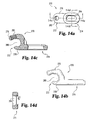
- Connector 270 includes a roughly C-shaped portion 272 and an extension portion 274.
- C-shaped portion 270 includes an upper portion 276 and a lower portion 278 defining an opening 280 into which a rod (not shown) can be fitted.
- Upper portion 276 includes a threaded bore 282 into which a set screw or other threaded piece (not shown) can be fitted to hold the rod within opening 280.
- Extension portion 274 includes a slot 284 which is configured substantially similarly to slot 108 of elongated member 100 and/or slot 30 of elongated member 22.
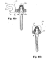
- Connector 270 can be used with bone bolt embodiments such as bone bolt 40 or 200, washer embodiments such as washers 42, 130 or 132, nut embodiments such as nuts 44 or 250, and stabilizer embodiments such as stabilizers 26 or 115, as further illustrated in FIGS 15a - 15b.
- kits containing a plurality of sizes and configurations of a single part, or a plurality of sizes and configurations of all parts that can be included in the system of the present invention.
- kits may include, for example, a set of elongated members 22 and/or 100 of various lengths and having differing numbers or orientations of slots and/or bores.
- a kit could include a set of elongated member having varying degrees of bend along longitudinal axis 106.
- Sets of washers, bolts, screws and nuts as disclosed herein can also be provided. Further, tools such as wrenches and screwdrivers compatible with the parts of the implant system of the present invention may also be included.
- the devices of the present invention are preferably constructed of sturdy bio-compatible materials, such as stainless steel, titanium, certain plastics, or other known materials.
Abstract
Description
- The present invention concerns orthopedic implants, particularly for the spine or long bones. Specifically, the present invention includes a bone anchor system having multi-axial capabilities, which may be used in conjunction with an orthopedic implant device such as a spinal plate or rod system.
- In the art of orthopedic surgery, and particularly in spinal surgery, it has long been known to affix an elongated member, such as a plate or rod, to bones in order to hold them and support them in a given position. For example, in a procedure to fuse damaged vertebrae, the vertebrae are positioned in a corrected position as required by the surgeon. A plate is placed adjacent to the bone, and bone anchors are employed to secure the plate to the bones. Bone screws or bolts are commonly utilized as the bone anchors, and with such anchors placement is accomplished by drilling one or more holes in the bone(s), and threading the anchors into the holes. An example of a prior art bone bolt is described in a book by Dr. Cotrel entitled New Instrumentation for Surgery of the Spine. Freund, London 1986. This bone bolt is shown in Figure 1. An anchor can be threaded into a hole through the plate, or the plate can be placed in position around the anchor after threading into the hole. The anchor and plate are then secured to each other to prevent relative movement. In this way, bones may be held and/or supported in proper alignment for healing.
- A spinal plate system or other similar implant system may have anchors that can be positioned at a number of angles with respect to the plate or other implant. Such a feature allows easier placement of implant systems or correction of positioning of an implant system, in that the bone anchors need not be precisely positioned in angular relation with respect to the implant. Rather, with a multi-axial capability, holes can be drilled in a bone at a convenient location and/or angle, for example, and screws can be inserted therein, with the connection between the plate and the anchor being angularly adjustable to provide sufficient force perpendicular to the plate/bone interface to secure the plate.
- The plate system disclosed in U.S. Patent No. 5,613,967 to Engelhardt, et al., discloses a slotted plate through which a bone screw extends. The screw includes cancellous threads for placement in bone, an intermediate section with an upper flat portion, and a machine-threaded section. The machine-threaded portion fits through the slot In the plate, and the plate abuts the flat portion of the screw or a flat washer imposed between the intermediate portion of the screw and the plate. A bracket is placed over the machine-threaded portion of the screw and the slotted plate, and a nut is threaded on the machine-threaded portion of the screw to anchor the screw and plate together. This apparatus does not provide the preferred multi-axial capability, as described above.
- U.S. Patent No. 5,084,048 to Jacob et al., discloses apparatus for damping a rod to a bone screw such that the longitudinal planes of the rod and screw are not perpendicular.
- U.S. Patent No. 5,234,431 describes a bone plate arrangement comprising a bone plate defining at least one aperture for receipt of a bone screw supported within a sleeve. The angular position of the sleeve, and thereby the bone screw, relative to the bone plate is adjustable.
- It is therefore an object of this invention to provide a spinal implant system having improved multi-axial capability and superior and strength and ease of use, particularly with respect to the spine.
- Another object of the present invention is to provide a locking mechanism having a plurality of locking locations along a slotted member.
- Still a further object of the present invention is in a preferred embodiment to provide an improved spine system with multi-axial capability and a plurality of locking locations along the systems.
- Other objects will be evident from the following specification.
- The present invention provides an orthopedic implant, comprising: a longitudinal member, said longitudinal member having a lower side for facing a bone, an upper side for facing away from a bone, and an aperture through said longitudinal member from said first side to said second side, said longitudinal member further including a longitudinal channel parallel to and between said first and second sides, said channel being substantially perpendicular to said aperture; a stabilizer having an opening therethrough bounded by a conical surface, said stabilizer further having a plurality of laterally extending fingers occupying said channel so that said stabilizer is in one of an infinite number of positions wherein said opening is adjacent to said aperture of said longitudinal member; a fixation member having a first threaded portion for fixing to a bone, a second threaded portion, and a diametrally enlarged portion between said first and second threaded portions, said enlarged portion including a plurality of torque transmission surfaces, and said fixation member extending through said stabilizer and said longitudinal member so that said enlarged portion contacts a portion of said surface bounding said opening of said stabilizer; a washer having a rounded top, said washer adapted for placement over said second threaded part of said fixation member and into contact with said second side of said longitudinal member; and a nut having a rounded underside and adapted to be threaded onto said second threaded portion of said fixation member and down onto said washer, to thereby lock said fixation member in place relative to said longitudinal member.
-
- FIG. 1 is an illustration of a bone bolt used in a prior art spinal implant system.
- FIG. 2 is a perspective view of one embodiment of the system of the present invention.
- FIG. 3 is a partial sectional view of the embodiment of the invention illustrated in FIG. 1.
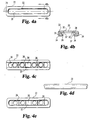
- FIG. 4a is a top view of one embodiment of an orthopedic plate used with the embodiment of the invention illustrated in FIG. 1.
- FIG. 4b is a cross sectional view of the embodiment of the orthopedic plate
illustrated in FIG. 4a, taken along the
lines 4b - - 4b in FIG. 4a. - FIG. 4c is a bottom view of the embodiment of the orthopedic plate illustrated in FIG. 4a, including a set of stabilizers according to the embodiment illustrated in FIGs. 7a and 7b.
- FIG. 4d is a side view of the embodiment of the orthopedic plate illustrated in FIG. 4a.
- FIG. 4e is a top view of the embodiment of the orthopedic plate along with stabilizers as illustrated in FIG. 4c.
- FIG. 5a is a side elevational view of one embodiment of a washer used in the embodiment of the invention illustrated in FIG. 1.
- FIG. 5b is a bottom view of the embodiment of the washer illustrated in FIG. 3a.
- FIG. 5c is a sectional view of the embodiment of the washer illustrated in FIG. 3a.
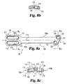
- FIG. 6a is a side elevational view of one embodiment of a break-off nut as used in the embodiment of the invention illustrated in FIG. 1.
- FIG. 6b is a bottom view of the embodiment of the break-off nut illustrated in FIG. 4a.
- FIG. 6c is a sectional view of the embodiment of the break-off nut illustrated in FIG. 4a.
- FIG. 7a is a top view of one embodiment of the stabilizer used in the embodiment of the invention illustrated in FIG. 1.
- FIG. 7b is a cross section of the embodiment of the stabilizer illustrated in FIG. 5a, taken along the direction of the arrows.
- FIG. 8a is a top view of an alternate embodiment of an orthopedic plate according to the present invention.
- FIG. 8b is a cross-sectional view, taken along the
lines 8b - - 8b in FIG. 8a and viewed in the direction of the arrows, of the embodiment of the orthopedic plate illustrated in FIG. 8a. - FIG. 8c is a cross-sectional view, taken along the lines of 8c - - 8c in FIG. 8a and viewed in the direction of the arrows, of the embodiment of the orthopedic plate illustrated in FIG 8a.
- FIG. 8d is an end view of the superior end of the embodiment of the orthopedic plate illustrated in FIG. 8a.
- FIG. 8e is a bottom view of the embodiment of the orthopedic plate illustrated in FIG. 8a.
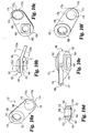
- FIG. 9a is a top view of an embodiment of a washer according to the present invention, viewed coaxially with a body portion of the washer.
- FIG. 9b is a side view of the embodiment of the washer illustrated in FIG. 9a.
- FIG. 9c is a bottom view of the embodiment of the washer illustrated in FIG. 9a.
- FIG. 9d is a cross-sectional view, taken along the
lines 9d - - 9d of FIG. 9b and viewed in the direction of the arrows, of the embodiment of the washer illustrated in FIG. 9a. - FIG. 9e is a cross-sectional view, taken along the
lines 9e - - 9e of FIG. 9b and viewed in the direction of the arrows, of the embodiment of the washer illustrated in FIG. 9a. - FIG. 9f is a top view of the embodiment of the washer illustrated in FIG 9a, viewed coaxially with an extension part of the washer.
- FIG. 10a is a top view of an embodiment of a washer according to the present invention, viewed coaxially with a body portion of the washer.
- FIG. 10b is a side view of the embodiment of the washer illustrated in FIG. 10a.
- FIG. 10c is a bottom view of the embodiment of the washer illustrated in FIG. 10a.
- FIG. 10d is a cross-sectional view, taken along the
lines 10d - - 10d of FIG. 10b and viewed in the direction of the arrows, of the embodiment of the washer illustrated in FIG. 10a. - FIG. 10e is a cross-sectional view, taken along the
lines 10e - - 10e of FIG. 10b and viewed in the direction of the arrows, of the embodiment of the washer illustrated in FIG. 10a. - FIG. 10f is a top view of the embodiment of the washer illustrated in FIG 9a, viewed coaxially with an extension part of the washer.
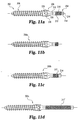
- FIG. 11a is a side view is an embodiment of a bone bolt of the present invention.
- FIG. 11b is a side view of another embodiment of the bone bolt illustrated in FIG. 11a.
- FIG. 11c is a side view of another embodiment of the bone bolt illustrated in FIG. 11a.
- FIG. 11d is a side view of another embodiment of the bone bolt illustrated in FIG. 11a.
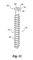
- FIG. 12 is a side view of an embodiment of a bone screw for use with present invention.
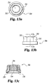
- FIG. 13a is a top view of an embodiment of a nut for use with the present invention.
- FIG. 13b is a side view of the embodiment of the nut illustrated in FIG. 13a.
- FIG. 13c is a cross-sectional view taken along the lines of 13c - - 13c and viewed in the direction of the arrows, of the embodiment of the nut illustrated in FIG. 13a.
- FIG. 14a is a top view of an embodiment of a rod-bolt connector for use with the present invention.
- FIG. 14b is a side view of the embodiment of the rod-bolt connector illustrated in FIG. 14a.
- FIG. 14c is a cross-sectional view, taken along the
lines 14c - - 14c of FIG. 14a and viewed in the direction of the arrows, of the embodiment of the rod-bolt connector illustrated in FIG. 14a. - FIG. 14d is a cross-sectional view, taken along the
lines 14d - - 14d of FIG. 14a and viewed in the direction of the arrows, of the embodiment of the rod-bolt connector illustrated in FIG. 14a. - FIG. 15a is a partial cut-away view of the embodiment of the rod-bolt connector illustrated in FIG. 14a with embodiments of a bone bolt, washer, nut and stabilizer of the present invention.
- FIG. 15b is a cross-sectional view, taken along the
lines 15b - - 15b of FIG. 15a and viewed in the direction of the arrows, of the embodiments of the rod-bolt connector, bone bolt, washer, nut and stabilizer illustrated in FIG. 15a. - FIG. 16a is a top view of a second embodiment of the stabilizer of the present invention.
- FIG. 16b is a side elevational view of the embodiment of the stabilizer illustrated in FIG. 16a.
- FIG. 16c is a cross-sectional view, taken along the
lines 16c-16c of FIG. 16b and viewed in the direction of the arrows, of the embodiment of the stabilizer illustrated in FIG. 16a. - FIG. 17a is a side elevational view of a third embodiment of the stabilizer of the present invention.
- FIG. 17b is a bottom view of the embodiment of the stabilizer illustrated in FIG. 17a.
- FIG. 17c is a cross-sectional view, taken along the
line 17c--17c of FIG. 17a and viewed in the direction of the arrows, of the embodiment of the stabilizer illustrated in FIG. 17a. - FIG. 17d is a side elevational view of a second version of the embodiment of the stabilizer illustrated in FIG. 17a.
-
- For the purposes of promoting an understanding of the principles of the invention, reference will now be made to the embodiment illustrated in the drawings and specific language will be used to describe the same. It will nevertheless be understood that no limitation of the scope of the invention is thereby intended, such alterations and further modifications in the illustrated device, and such further applications of the principles of the invention as illustrated therein, being contemplated as would normally occur to one skilled in the art to which the invention relates, the scope being defined by the claims.
- Referring generally to FIG. 2, one embodiment of an
orthopedic implant system 20 according to the present invention is illustrated. In that embodiment,implant system 20 includes anelongated member 22, a pair ofbone anchor assemblies 24, and a set of supports orstabilizers 26. Differing numbers of any of those elements may be utilized without departing from the scope of this invention. For example, a plurality ofelongated members 22 can be used in conjunction with each other, or a greater or lesser number ofbone anchor assemblies 24 orstabilizers 26 may be used, depending upon the configuration of the elongated member, the medical problem to be addressed, and/or any other factors. The present invention contemplates at least oneelongated member 22, at least onebone anchor assembly 24 and at least onestabilizer 26. - Referring now generally to FIGS. 4a - 4e, there is shown an embodiment of
elongated member 22 according to the present invention.Elongated member 22 is in the form of a generally rectangular flat plate and includes a generallylongitudinal slot 30 through the thickness ofelongated member 22. Withinslot 30 is formed aledge 32.Elongated member 22 also includes a pair of downwardly-extendingarms 34 substantially along the length of both sides ofelongated member 22.Arms 34 have an inwardly-extendingledge 36 along substantially the entire length ofarms 34. - Referring now generally to FIGS. 2 -7, there is shown one preferred embodiment of the
bone anchor assembly 24 of the present invention. Generally,bone anchor assembly 24 includes abone bolt 40, anarcuate washer 42, and a break-offnut 44. In the illustrated embodiment,bone bolt 40 includes a bone-engagingportion 46 havingcancellous threads 48 thereon.Bone bolt 40 also includes aproximal portion 50, which is threaded with machine threads. Betweenproximal portion 50 and bone-engagingportion 46, there is anintermediate portion 54 which has a rounded configuration. In one specific embodiment, the rounded shoulder has a spherical configuration. The bone bolt is more specifically described below. - Referring generally to FIGS. 5a - 5c,
arcuate washer 42 ofbone anchor assembly 24 has a generallycylindrical body 60, a rounded orconical head 62, aunderside projection 64, and anaperture 66 therethrough.Aperture 66 is bounded byinner walls washer 42. In the illustrated embodiment,inner wall 68 is conical or tapered such thataperture 66 decreases in diameter fromhead 62 towardbody 60, andinner wall 70 is substantially cylindrical. For example,inner wall 70 may not be contiguous withinner wall 68, orwalls surface bounding aperture 66.Projection 64 also boundsaperture 66, and in a specific embodiment the outer dimension ofprojection 64 is approximately square and sized to fit withinslot 30 and atopledge 32 ofelongated member 22. - Further included in
bone anchor assembly 24 is a break-offnut 44. As shown more clearly in FIGS. 6a-c, break-offnut 44 includes an upper break-offportion 76 and anut portion 78. Both break-offportion 76 andnut portion 78 preferably have a hexagonal outer shape, although any known configuration of the outer portion of break-offportion 76 andnut portion 78 that will allow transmission of torque to one or both can be used with the present invention. - Break-off
nut 44 includes alongitudinal bore 80 therethrough.Bore 80, in a specific embodiment, is substantially cylindrical within break-offportion 76, and is substantially cylindrical with afemale thread 82 withinnut portion 78. Approaching the bottom end ofnut portion 78, bore 80 is bounded by asurface 84 for complementary mating withhead 62 ofarcuate washer 42. While it is contemplated that the surfaces may have any configuration, in apreferred embodiment surface 84 is generally spherical, having a radius larger than the radius ofbore 80, and substantially the same radius as the generallyspherical head 62 ofwasher 42. Break-offnut 44 also includes a groove or weakenedarea 86 that allows shearing separation of break-offportion 76 fromnut portion 78 after break-offnut 44 has been tightened sufficiently.
Also included inimplant system 20 are one or more stabilizers or supports 26 (FIGS 7a and 7b).Stabilizer 26, in one embodiment, has an approximatelysquare body 90 with an extendingfinger portion 92 on opposite sides ofstabilizer 26.Stabilizer 26 also has abore 94 therethrough.Bore 94 is bounded by a conical or taperedwall 96 and substantiallycylindrical wall 98. For example,walls walls Fingers 92 ofstabilizer 26 are shaped and dimensioned to fit withinslot 39 ofelongated member 22 such thatfingers 92abut ledges 36 andundersurface 37 ofelongated member 22. In this embodiment,stabilizer 26 has a substantiallyflat bottom surface 97. One ormore stabilizers 26 may be inserted intoslot 39 via an open end ofelongated member 22, and untilimplant system 20 is finally tightened or locked as described below, are slidable alongledges 36 ofelongated member 22. - A second embodiment of stabilizer 26' is illustrated in FIGS. 16a-16c. Stabilizer 26' is like
stabilizer 26 in most respects. However, stabilizer 26' has a body 90' approximately in the shape of a parallelogram. Finger portions 92', bore 94' and tapered wall 96' are substantially similar tofinger portions 92, bore 94, and taperedwall 96 ofstabilizer 26, described and illustrated above. For example, tapered wall 96' could be contiguous with or separate from a cylindrical wall which also bounds bore 94'. Fingers 92' are shaped in dimension to fit withinslot 39 ofelongated member 22 such that figures 92'abut ledges 36 and undersurface 37 ofelongated member 22. One or more stabilizers 26' may be inserted intoslot 39 via an open end ofelongated member 22, and untilimplant system 20 is finally tightened or locked as described below, are slideable alongledges 36 ofelongated member 22. The parallelogram configuration of stabilizer 26' allows close center line-to-center line placement of bone bolts or screws when multiple stabilizers 26' are placed adjacent each other, and can reduce the overall thickness of the plate and stabilizer combination required for successful fixation. - In a third embodiment,
stabilizer 26" is depicted in FIGS. 17a-17c.Stabilizer 26" has an approximatelyrectangular body 90" with extendingfinger portions 92" on opposite sides ofstabilizer 26".Finger portions 92", likefinger portions 92 and 92', haveflat undersides 93" in one embodiment. Alternatively, in another embodiment (FIG. 17d)finger portions 92" (and by extension,finger portions 92 and 92' ofstabilizers 26 and 26') can have convexly rounded undersides 93a".Stabilizer 26" also has abore 94" therethrough.Bore 94" is preferably bounded by a conical or taperedwall 96" as discussed above with reference tostabilizers 26 and 26'.Stabilizer 26" also includes arounded bottom surface 97" that substantially surrounds the lower opening ofbore 94". In one specific embodiment ofstabilizer 26" rounded bottom 97" has a configuration of a portion of a cylinder.Fingers 92" ofstabilizer 26" are shaped and dimensioned to fit withinslot 39 ofelongated member 22 such thatfingers 92"abut ledges 36 and undersurface 37 ofelongated member 22. One ormore stabilizers 26" may be inserted intoslot 39 via an open end ofelongated member 22, and untilimplant system 20 is finally tightened or locked as described below, are slideable alongledges 36 ofelongated member 22. While the description below specifically names onlystabilizer 26, it is understood thatstabilizers 26' and 26" are used in the same manner. - Referring now generally to FIGS. 2 and 3,
implant system 20 is assembled and used as follows. After the surgeon has drilled one or more holes into a bone or bones,bone bolt 40 is threaded into the hole via cancellous threads on bone-engagingportion 46. Afterbone bolt 40 is securely affixed to the bone, elongatedmember 22 including a fitted support orstabilizer 26 is placed overbone bolt 40, so thatproximal portion 50 ofbone bolt 40 extends throughbore 94 ofstabilizer 26 andslot 30 ofelongated member 22, and such thatintermediate portion 54 ofbone bolt 40 is within or adjacent to bore 94 ofstabilizer 26.Washer 42 is placed overproximal portion 50 ofbone bolt 40, so thatproximal portion 50 extends throughaperture 66 ofwasher 42, and so that underside surface 63 ofwasher 42 rests onelongated member 22 andunderside projection 64 ofwasher 42 abutsledge 32 withinslot 30 ofelongated member 22. In the embodiment in whichprojection 64 has an approximately square outer configuration,washer 42 will not be able to rotate aboutbone bolt 40 whenprojection 64 is withinslot 30 ofelongated member 22. Whenwasher 42 is in place, break-offnut 44 is loosely threaded onto machine thread 52 ofbone screw 40, such thatsurface 84 ofnut portion 78 is in adjustable contact with or adjacent to head 62 ofwasher 42. Elongated member can then be adjusted with respect tobone bolt 40, andbone bolt 40 may thereby form one of a variety of angles with respect toelongated member 22. The rounded part 56 ofintermediate portion 54 ofbone bolt 40 is able to articulate withinbore 94 andwall portion 96 ofstabilizer 26, andinner wall 68 ofwasher 42 permitsproximal portion 50 ofbone bolt 40 to correspondingly occupy various angular positions with respect towasher 42 andelongated member 22. - After
elongated member 22 is properly positioned with respect tobone bolt 40, break-offnut 44 is tightened. As break-offnut 44 is tightened, the torque on break-offportion 76 increases, until break-offportion 76 shears away fromnut portion 78 atgroove 86. Preferably, groove 86 is above the uppermost portion ofbone screw 40 to inhibit irritation to surrounding tissue that might be caused by a protruding post.Surface 84 ofnut portion 78, being configured similarly or identically to head 62 ofwasher 42, is able to matingly engage any portion ofhead 62, enabling secure, tight contact betweennut portion 78 andwasher 42 regardless of the angle betweenbone bolt 40 andelongated member 22. - An
alternative embodiment 99 of the present invention is illustrated in FIGS: 8 - 13. Referring generally to FIG. 8, there is shown anelongated member 100 according to that alternative embodiment.Elongated member 100 includes asuperior end 102, an inferior orcaudal end 104, and a longitudinal axis 106 generally extending there between. Typically, when implantedsuperior end 102 andinferior end 104 will be oriented as cephalad and caudal ends, respectively. -
Superior end 102 includes a pair oflongitudinal slots Slot 108 has a configuration very similar to the arrangement ofslot 30 inelongated member 22.Slot 108 includes aledge 112 near the upper part of elongated 100, which substantially encirclesslot 108 in one specific embodiment. It is contemplated that in another embodiment,slot 108 may include twoledges 112, each running along substantially the entire length of a longitudinal side ofslot 108. Preferably,side walls 113, immediatelyadjacent ledges 112, form a rectangular configuration in the upper portion ofslot 108. Slot 108 also has alower ledge 114 that runs substantially along each longitudinal side ofslot 108. A stabilizer 115 (similar tostabilizer 26 described above) may be placed to bear againstledge 114 as previously discussed with respect to the embodiment of FIG. 2.Slot 110 includes a first arcuate orconical surface 116 near the upper surface ofelongated member 100, and a second arcuate orconical surface 118 near the lower surface ofelongated member 100. In a specific embodiment, surfaces 116 and 118 are substantially circular in cross-section. In a preferred aspect, the radius ofsurface 118 is larger than that ofsurface 116. -
Inferior end 104 ofelongated member 100 includes a pair ofbores Bore 120 includesside walls 123 and aledge 124 near the upper surface of elongated member of 100.Side walls 123 define a generally square opening. Bore 120 further includeswall 126 which tapers outward in a substantially conical shape from upper to lower surfaces ofelongated member 100.Bore 122 is a substantially circular bore, having anarcuate surface 128 near the upper surface ofelongated member 100. In a preferred embodiment,arcuate surface 128 is spherical. - Additionally,
elongated member 100 includes a bend along axis 106, separatingelongated member 100 intoside portions side portions elongated member 100 are contemplated as within the scope of the present invention, as may be required by the configurations of the bones to whichelongated member 100 is to be attached or other factors. - The embodiment of the
implant system 99 incorporatingelongated member 100 also includes superior orcephalad washer 130 and inferior orcaudal washer 132. Referring to FIGS. 9a-f,superior washer 130 includes abody portion 134 having an conical orrounded head 136 and anunderside 137 having aprojection 138, and alateral extension portion 140. In the illustrated embodiment ofwasher 130,head 136 forms a portion of a sphere, andunderside projection 138 is flat and in the general form of a square with rounded corners, with the sides of the square of a size slightly less than the width ofslot 108 ofelongated member 100. Anaperture 142 extends throughbody 134 ofwasher 130. Anupper wall portion 144bounds aperture 142, and is tapered fromhead 136 toward the bottom ofwasher 130. Alower wall portion 146 is generally cylindrical. However, other wall configurations are possible, for example,wall portions head 136 toprojection 138. -
Lateral extension portion 140 ofwasher 130 includes a C-clip portion 148, which encloses most of anaperture 150, and downwardly extendingflanges clip portion 148 has a pair offingers Fingers conical projection 156 at their respective upper portions. The interior opening defined byprojection 156 has a slightly smaller diameter than the interior opening defined bywalls Flanges extension portion 140 slightly smaller than the width ofslot 110 ofelongated member 100.Washer 130 also includes a bend inlateral extension portion 140 that is complementary to the bend along longitudinal axis 106 ofelongated member 100. The inside angle B formed by the bend inwasher 130 is approximately the same as angle A ofelongated member 100. - In use,
washer 130 is fitted intoslots elongated member 100. Specifically,body portion 134 is placed onslot 108 such thatunderside 137 ofbody portion 134 rests onelongated member 100 andprojection 138 ofbody 134 is fitted intoslot 108 and rests onledge 112.Flanges extension portion 140 are fitted intoslot 110. In this configuration,washer 130 cannot rotate with respect toelongated member 100 because of the respective fits between (a)projection 138 and the sides ofslot 108, (b)flanges slot 110, and (c) the bend in bothwasher 130 andelongated member 100. - Referring now generally to FIGS. 10a - f, an embodiment of
inferior washer 132 is illustrated.Washer 132 includes abody 160 having a conical orrounded head 162 and anunderside 163 having a substantiallysquare projection 164, and anextension 166.Body 160 has anaperture 168 extending therethrough, extending fromhead 162 toprojection 164.Aperture 168 is bounded bywall sections wall section 170 is conically tapered fromhead 162 towardunderside projection 164, andwall section 172 is substantially cylindrical. Other configurations are possible, however, such aswall sections -
Lateral extension 166 includes a C-clip portion 174, which encircles most of substantiallycylindrical aperture 176. C-clip portion 174 has a pair offingers Fingers conical projection 178 at their respective upper portions. The opening defined byprojection 178 has a diameter slightly smaller than the diameter defined bywalls Washer 132 also includes a bend inlateral extension portion 166 that is complementary to the bend along longitudinal axis 106 ofelongated member 100. The inside angle C formed by the bend inwasher 132 is approximately the same as angle A ofelongated member 100. - Referring generally to FIG. 11, there is shown a more detailed depiction of a form of bone bolt 200 which can be used with
elongated member 100 or elongatedmember 22. Bone bolt 200 includes a bone-engagingportion 202, aproximal portion 204, and anintermediate portion 206. Preferably, bone-engagingportion 202 includescancellous thread 208, which winds along the length of bone-engagingportion 202 untilthread 208 adjoinsintermediate portion 206. As the thread pattern nearsintermediate portion 206, the root diameter of the thread increases. -
Proximal end 204 includes ashaft portion 210 adjoiningintermediate portion 206, a threadedportion 212 proximal ofshaft portion 210, and a break-offportion 214 proximal of threadedportion 212. In a specific embodiment, break offportion 214 includes torque applying surfaces 216 (for example, hexagonal outer surfaces) to be engaged by a wrench or other nut-driver, and a groove or weakenedportion 218. When bolt 200 is secure, further torque applied totorque applying surfaces 216 will cause break-offportion 214 to shear from threadedportion 212 at groove or weakenedportion 218. Break-offportion 214 is preferably configured so that shear occurs when a relatively light torque is applied, e.g. in the range of 10 - 11 newton-meters.Surface 216 may be used to prevent bolt rotation while the bolt is connected to an elongated member by a nut.Intermediate portion 206 of bolt 200 is generally rounded, and includes a set of flattenedareas 220. In a specific embodiment, flattenedareas 220 are uniformly spaced around the circumference ofintermediate portion 206, in a hexagonal arrangement - Referring to FIGS. 11b - 11d, there are illustrated
bone bolts Bone bolt 200a includes the parts of bone bolt 200 identified above, but does not include break-offportion 214.Bone bolt 200b includes, in addition to the features of bone bolt 200, a machine threadedsection 217 on break-offportion 214.Bone bolt 200c includes a longer machine threaded section 217'.Machine threads 217 and 217' may be used to enable the surgeon to shear off break-offportion 214 without losing break-offportion 214 or dropping it into the patient. Further, maching threads 217' have sufficient length to allow reduction of stripped vertebra. A cannulated tool having a female thread at its distal end and inner surfaces for torque application (e.g., hexagonal inner surfaces for engaging torque application surfaces 216 of break-off section 214) could be threaded ontomachine threads 217 or 217', and the inner torque surfaces of the tool engaged with break-offportion 214. When break-offportion 214 is sheared frombolt portion 214 is held by the tool by virtue of the interengaged female tool thread andmachine threads 217 or 217' of break-offportion 214 ofbolt - Now referring generally to FIG. 12, there is illustrated
bone screw 230 of the present invention.Bone screw 230 includes abone engaging portion 232 having cancellous threads 243 thereon, and ahead portion 236.Head portion 236 includes a lower rounded surface 248 and an upperrounded surface 240. In a specific embodiment, surfaces 238 and 240 are separated by a generallycylindrical portion 242.Head 236 also includes a tool-engagingrecess 244. Tool-engagingrecess 244 may be of any suitable configuration, including hexagonal, hexalobed, or other configuration. - Referring now generally to FIGS. 13a - c,
nut 250 of the present invention is illustrated.Nut 250 includes outer torque application surfaces 252 and anaperture 254 extending longitudinally throughnut 250.Aperture 254 includesthreads 256, which extend from the top ofnut 250 toward the bottom ofnut 250.Aperture 254 widens near the bottom ofnut 250, and is bounded bywalls 258. In a preferred embodiment,walls 258 are substantially spherical. However, other configurations are contemplated, such as conical. - In use,
elongated member 100,washers screw 230 andnut 250 are used in connection withstabilizer cancellous threads 208. Bolts 200 are threaded into the drilled holes, and when bolts 200 are satisfactorily seated.Elongated member 100 is placed over bolts 200, so thatproximal portions 204 of bolts 200 extend throughslot 108 and bore 120, respectively. In the embodiment in whichstabilizer 26 is placed inslot 108 onledge 114 ofelongated member 100 theproximal portion 204 of one bolt 200 extends through the aperture ofstabilizer 26 as well. Whenelongated member 100 is properly placed, the sides ofslot 108 are preferably adjacent to one or moreflat portions 220 of one bolt 200. -
Washer 130 is then fitted so that the bolt 200 extending throughslot 108 also extends throughaperture 142 ofwasher 130,projection 138 ofwasher 130 fits withinslot 108 and on top ofledge 112 ofelongated member 100, and downwardly-extendingflanges slot 110 ofelongated member 100. Positioned thusly,washer 130 is not able to rotate about bolt 200 due to the engagement ofprojection 138 withslot 108 andflanges slot 110.Washer 132 is fitted over the bolt 200 withinbore 120, so thatunderside projection 164 ofwasher 132 rests onledge 124 withinbore 120, and such thataperture 176 ofwasher 132 and bore 128 ofelongated member 100 are roughly aligned. - Holes may be drilled through
bore 128 and slot 110 forscrews 230. Alternatively, holes forscrews 230 may be drilled prior tofitting washers elongated member 100, or may be drilled at the same time holes for bolts 200 are drilled. Abone screw 230 is threaded into a hole in the bone tissue throughaperture 176,washer 132, and bore 128 atinferior end 104 ofelongated member 100, and aseparate screw 230 is threaded into a separate hole in the bone tissue throughaperture 150 ofwasher 130 and slot 110 atsuperior end 102 ofelongated member 100. Asscrew 230 is threaded into the bone,head 236 comes in contact with C-clip portion 174 ofwasher 132. Lowerrounded surface 238 ofscrew 230, as the screw is threaded into the bone, pushes outward on taperedsurface 178 ofwasher 132, forcingfingers clip portion 174 to open. Whenscrew 230 is threaded far enough so thatcylindrical portion 242 substantially passestapered portion 178,fingers clip portion 174 close together, thereby preventingscrew 230 from backing out under loads. In one embodiment, the closing offingers second screw 230 into bone tissue throughwasher 130 andslot 108. C-clip portions portions cylindrical portion 242 ofscrew 230 backward or forward throughportions clip portions fingers aperture washer - When it is determined that
elongated member 100 is in the proper position with respect to bolts 200 and/orscrews 230,nuts 250 are threaded onto threadedportions 212 of bolts 200.Surface 258 of onenut 250 is generally configured with a substantially similar shape to head 162 ofwasher 132, andsurface 258 of asecond nut 250 is generally configured with a substantially similar shape to head 136 ofwasher 130. Thus, asnuts 250 are torqued onto bolts 200,respective surfaces 258 are pressed againstsurfaces upper surfaces 216 may be engaged by a tool during nut tightening to resist rotation of the bolt and after nut tightening torque may be applied tosurfaces 216 to shear off the post. -
Elongated member 100 may be positioned with respect to bolts 200 such that the longitudinal axes of bolts 200 are not perpendicular tosides Wall portion 144 ofwasher 130 andwall portion 170 ofwasher 132 are tapered, as noted above, to accommodate the positioning of a bolt 200 along a variety of angles with respect toelongated member 100. Further,wall surface 96 of astabilizer 26 placed withinslot 108 onledge 114 ofelongated member 100 also accommodates the angle of a bolt 200. In the case in which a bolt 200 is not perpendicular with respect to slot 108 and/or bore 120,nut 250 is not squarely on top ofhead washer surface 258 ofnut 250 andhead surface 258 and heads 162 and 136. - For example,
tabs washer 130 may be left out as long asunderside portion 138 ofwasher 130 and slot 108 ofelongated member 100 are configured to prevent rotation ofwasher 130 with respect toelongated member 100 whenwasher 130 is engaged toelongated member 100. Moreover,underside projections washers extension portion washers extension portion projection - Referring generally to FIGS. 14a - 15b, there is shown an embodiment of a rod-
bolt connector 270.Connector 270 includes a roughly C-shapedportion 272 and anextension portion 274. C-shapedportion 270 includes anupper portion 276 and alower portion 278 defining anopening 280 into which a rod (not shown) can be fitted.Upper portion 276 includes a threadedbore 282 into which a set screw or other threaded piece (not shown) can be fitted to hold the rod withinopening 280.Extension portion 274 includes aslot 284 which is configured substantially similarly to slot 108 ofelongated member 100 and/or slot 30 ofelongated member 22.Connector 270 can be used with bone bolt embodiments such asbone bolt 40 or 200, washer embodiments such aswashers nuts stabilizers - The parts of the implant system of the present invention may be made available in the form of kits containing a plurality of sizes and configurations of a single part, or a plurality of sizes and configurations of all parts that can be included in the system of the present invention. Such kits may include, for example, a set of
elongated members 22 and/or 100 of various lengths and having differing numbers or orientations of slots and/or bores. In the case ofelongated member 100, a kit could include a set of elongated member having varying degrees of bend along longitudinal axis 106. Sets of washers, bolts, screws and nuts as disclosed herein can also be provided. Further, tools such as wrenches and screwdrivers compatible with the parts of the implant system of the present invention may also be included. - The devices of the present invention are preferably constructed of sturdy bio-compatible materials, such as stainless steel, titanium, certain plastics, or other known materials.
- While the invention has been illustrated and described in detail in the drawings and foregoing description, the same is to be considered as illustrative and not restrictive in character, it being understood that only the preferred embodiment has been shown and described and that all changes and modifications that come within the scope of the invention as defined in the claims are desired to be protected.
Claims (19)
- An orthopedic implant (20), comprising:a longitudinal member (22; 100), said longitudinal member (22; 100) having a lower side for facing a bone, an upper side for facing away from a bone, and an aperture (30; 108) through said longitudinal member from said first side to said second side, said longitudinal member (22; 100) further including a longitudinal channel (39) parallel to and between said first and second sides, said channel (39) being substantially perpendicular to said aperture (30; 108);a stabilizer (26; 26'; 26") having an opening (94; 94'; 94") therethrough bounded by a conical surface (96; 96'; 96"), said stabilizer (26; 26'; 26") further having a plurality of laterally extending fingers (92; 92'; 92") occupying said channel (39) so that said stabilizer (26; 26'; 26") is in one of an infinite number of positions wherein said opening (94; 94'; 94") is adjacent to said aperture (30; 108) of said longitudinal member (22; 100);a fixation member (40; 200a; 200b; 200c) having a first threaded portion (46; 202) for fixing to a bone, a second threaded portion (50; 212), and a diametrally enlarged portion (54; 206) between said first and second threaded portions (46; 202, 50; 212), said enlarged portion (54; 206) including a plurality of torque transmission surfaces, and said fixation member (40; 200a; 200b; 200c) extending through said stabilizer (26; 26'; 26") and said longitudinal member (22; 100) so that said enlarged portion (54; 206) contacts a portion of said surface (96; 96'; 96") bounding said opening (94; 94'; 94") of said stabilizer (26; 26'; 26");a washer (42; 130; 132) having a rounded top (62; 136; 162), said washer (42; 130; 132) adapted for placement over said second threaded part (50; 212) of said fixation member (40; 200a; 200b; 200c) and into contact with said second side of said longitudinal member (22; 100); anda nut (44; 250) having a rounded underside (84; 258) and adapted to be threaded onto said second threaded portion (50; 212) of said fixation member (40; 200a; 200b; 200c) and down onto said washer (42; 130; 132), to thereby lock said fixation member (40; 200a; 200b; 200c) in place relative to said longitudinal member (22; 100).
- The implant of claim 1, wherein said channel (39) is continuous and extends through substantially the entire length of said longitudinal member (22; 100).
- The implant of claims 1 or 2, further comprising at least one additional stabilizer (26; 26'; 26") each having an opening (94; 94'; 94") therethrough bounded by a conical surface (96; 96'; 96"), said at least one additional stabilizer (26; 26'; 26") further each having a plurality of lateral fingers (92; 92'; 92") occupying said channel (39) so that said at least one additional stabilizer (26; 26'; 26") is in a preselected one of an infinite number of positions wherein said opening (94; 94'; 94") of said at least one additional stabilizer (26; 26; 26") is adjacent to said aperture (30; 108) of said longitudinal member (22; 100).
- The implant of any of claims 1-3, further comprising at least one additional fixation member (40; 200a; 200b; 200c) each having a first threaded portion (46; 202) for fixing to a bone, a second threaded portion (50; 212), and a diametrally enlarged portion (54; 206) between said first and second threaded portions (46; 202, 50; 212), said enlarged portion (54; 202) of said at least one additional fixation member (40; 200a; 200b; 200c) including a plurality of torque transmission surfaces, and said at least one additional fixation member (40; 200a; 200b; 200c) extending through a corresponding one of said at least one additional stabilizer (26; 26'; 26") and said longitudinal member (22; 100) so that said enlarged portion (54; 206) of said at least one additional fixation member (40; 200a; 200b; 200c) contacts a portion of said surface bounding (96; 96'; 96") said opening of said corresponding stabilizer (26; 26'; 26").
- The implant of any claims 1-4, wherein said opening (94; 94'; 94") in said stabilizer (26; 26; 26") has a longitudinal axis, and said stabilizer substantially forms a parallelogram in a plane substantially perpendicular to said axis.
- The implant of any of claims 1-5, wherein said stabilizer (26; 26'; 26") substantially forms a square in a plane substantially perpendicular to said axis.
- The implant of any claims 1-6, wherein said washer (42; 130; 132) has a bottom surface for contacting said longitudinal member (22; 100) that includes a substantially flat portion (63; 137; 163) and a projection (64; 138; 164) extending substantially perpendicularly from said bottom surface.
- The implant of claim 7, wherein said longitudinal member (22; 100) has a ledge (32; 112; 124) within a said aperture (30; 108) and said aperture (30; 108) is bounded above said ledge (32; 112; 124) by substantially parallel wall sections, and said projection (64; 138; 164) of said washer (42; 130; 132) is configured to fit within said aperture (30; 108) and rest on said ledge (32; 112; 124).
- The implant of claim 8, wherein said projection (64; 138; 164) of said washer (42; 130; 132) is configured to cooperate with said substantially parallel wall sections to minimize rotation of said washer (42; 130; 132) with respect to said longitudinal member (22; 100).
- The implant of claim 9, wherein said projection (64; 138; 164) is substantially square.
- The implant of any of claims 1-10, wherein said washer (42; 130; 132) includes a hole (66; 142; 168) therethrough bounded by a wall (68; 144; 170, 70; 146; 172) that has a conical portion (68; 144; 170).
- The implant of claim 11, wherein said wall (68; 144; 170, 70; 146; 172) which bounds said hole (66; 142; 168) has a conical upper portion.
- The implant of any preceding claim, wherein said nut (44; 250) includes a break-off portion (76) that is severed when a torque exceeding a predetermined amount is applied to said break-off portion (76).
- The implant of any preceding claim, wherein said longitudinal member (22; 100) further includes a hole (120), and further comprising a screw member (230) having a thread portion (232) at one end and a head portion (236) having a rounded part at the other end.
- The implant of any preceding claim, wherein said washer (130; 132) further includes a body portion (134; 160) and a flange portion (140; 166) extending laterally from said body portion (134; 160), said flange (140; 166) including a C-clip (148; 174).
- The implant of claim 15, wherein said longitudinal member (100) has a second aperture (108; 122) and in use, said C-clip (148; 174) of said washer (130; 132) extends above said second aperture (108; 122).
- The implant of claims 15 or 16, further comprising a screw (230) having a threaded portion (232) and a head portion (236), in use, said screw (230) extending through said C-clip (148; 174) and into a bone.
- The implant of claim 17, wherein said head portion (236) of said screw (230) is larger than an inner diameter of said C-clip (148; 174).
- The implant of any preceding claim, wherein said second threaded portion (50; 212) of said fixation member (40; 200a; 200b; 200c; 200b) includes a break-off groove (218).
Priority Applications (1)
| Application Number | Priority Date | Filing Date | Title |
|---|---|---|---|
| EP05077207A EP1656896B1 (en) | 1999-04-16 | 2000-04-13 | Multi-axial bone anchor system |
Applications Claiming Priority (7)
| Application Number | Priority Date | Filing Date | Title |
|---|---|---|---|
| US12958799P | 1999-04-16 | 1999-04-16 | |
| US129587P | 1999-04-16 | ||
| US14977499P | 1999-08-19 | 1999-08-19 | |
| US149774P | 1999-08-19 | ||
| US09/526,189 US6280445B1 (en) | 1999-04-16 | 2000-03-15 | Multi-axial bone anchor system |
| US526189 | 2000-03-15 | ||
| PCT/US2000/009758 WO2000062692A2 (en) | 1999-04-16 | 2000-04-13 | Multi-axial bone anchor system |
Related Child Applications (1)
| Application Number | Title | Priority Date | Filing Date |
|---|---|---|---|
| EP05077207A Division EP1656896B1 (en) | 1999-04-16 | 2000-04-13 | Multi-axial bone anchor system |
Publications (2)
| Publication Number | Publication Date |
|---|---|
| EP1187568A2 EP1187568A2 (en) | 2002-03-20 |
| EP1187568B1 true EP1187568B1 (en) | 2005-11-09 |
Family
ID=27383902
Family Applications (2)
| Application Number | Title | Priority Date | Filing Date |
|---|---|---|---|
| EP05077207A Expired - Lifetime EP1656896B1 (en) | 1999-04-16 | 2000-04-13 | Multi-axial bone anchor system |
| EP00922104A Expired - Lifetime EP1187568B1 (en) | 1999-04-16 | 2000-04-13 | Multi-axial bone anchor system |
Family Applications Before (1)
| Application Number | Title | Priority Date | Filing Date |
|---|---|---|---|
| EP05077207A Expired - Lifetime EP1656896B1 (en) | 1999-04-16 | 2000-04-13 | Multi-axial bone anchor system |
Country Status (9)
| Country | Link |
|---|---|
| US (2) | US6280445B1 (en) |
| EP (2) | EP1656896B1 (en) |
| JP (1) | JP4276791B2 (en) |
| AT (2) | ATE511386T1 (en) |
| AU (1) | AU768045B2 (en) |
| CA (1) | CA2370056A1 (en) |
| DE (1) | DE60023886T2 (en) |
| ES (1) | ES2251992T3 (en) |
| WO (1) | WO2000062692A2 (en) |
Cited By (1)
| Publication number | Priority date | Publication date | Assignee | Title |
|---|---|---|---|---|
| US7905907B2 (en) | 2003-10-21 | 2011-03-15 | Theken Spine, Llc | Internal structure stabilization system for spanning three or more structures |
Families Citing this family (247)
| Publication number | Priority date | Publication date | Assignee | Title |
|---|---|---|---|---|
| KR100509625B1 (en) * | 1998-05-19 | 2005-08-23 | 신테스 아게 츄어 | Osteosynthetic implant with an embedded hinge joint |
| FR2781663B1 (en) * | 1998-07-30 | 2000-10-13 | Materiel Orthopedique En Abreg | SPINAL OSTEOSYNTHESIS DEVICE |
| US6283967B1 (en) | 1999-12-17 | 2001-09-04 | Synthes (U.S.A.) | Transconnector for coupling spinal rods |
| US6280445B1 (en) * | 1999-04-16 | 2001-08-28 | Sdgi Holdings, Inc. | Multi-axial bone anchor system |
| US6315779B1 (en) * | 1999-04-16 | 2001-11-13 | Sdgi Holdings, Inc. | Multi-axial bone anchor system |
| US7833250B2 (en) | 2004-11-10 | 2010-11-16 | Jackson Roger P | Polyaxial bone screw with helically wound capture connection |
| US6740088B1 (en) | 2000-10-25 | 2004-05-25 | Sdgi Holdings, Inc. | Anterior lumbar plate and method |
| US6726689B2 (en) * | 2002-09-06 | 2004-04-27 | Roger P. Jackson | Helical interlocking mating guide and advancement structure |
| US8377100B2 (en) | 2000-12-08 | 2013-02-19 | Roger P. Jackson | Closure for open-headed medical implant |
| ATE271354T1 (en) * | 2001-03-09 | 2004-08-15 | Co Ligne Ag | ELONGATED IMPLANT |
| US6764489B2 (en) * | 2001-03-27 | 2004-07-20 | Novasive, Inc | Hinged anterior thoracic/lumbar plate |
| US6641583B2 (en) * | 2001-03-29 | 2003-11-04 | Endius Incorporated | Apparatus for retaining bone portions in a desired spatial relationship |
| FR2823095B1 (en) * | 2001-04-06 | 2004-02-06 | Ldr Medical | RACHIS OSTEOSYNTHESIS DEVICE AND PLACEMENT METHOD |
| US20070055249A1 (en) * | 2003-06-20 | 2007-03-08 | Jensen David G | Bone plates with intraoperatively tapped apertures |
| US7537604B2 (en) * | 2002-11-19 | 2009-05-26 | Acumed Llc | Bone plates with slots |
| US20050234458A1 (en) * | 2004-04-19 | 2005-10-20 | Huebner Randall J | Expanded stabilization of bones |
| US7153309B2 (en) * | 2002-11-19 | 2006-12-26 | Acumed Llc | Guide system for bone-repair devices |
| US20050240187A1 (en) * | 2004-04-22 | 2005-10-27 | Huebner Randall J | Expanded fixation of bones |
| US7717945B2 (en) * | 2002-07-22 | 2010-05-18 | Acumed Llc | Orthopedic systems |
| US7862587B2 (en) | 2004-02-27 | 2011-01-04 | Jackson Roger P | Dynamic stabilization assemblies, tool set and method |
| US8292926B2 (en) | 2005-09-30 | 2012-10-23 | Jackson Roger P | Dynamic stabilization connecting member with elastic core and outer sleeve |
| US8353932B2 (en) | 2005-09-30 | 2013-01-15 | Jackson Roger P | Polyaxial bone anchor assembly with one-piece closure, pressure insert and plastic elongate member |
| US10729469B2 (en) | 2006-01-09 | 2020-08-04 | Roger P. Jackson | Flexible spinal stabilization assembly with spacer having off-axis core member |
| US10258382B2 (en) | 2007-01-18 | 2019-04-16 | Roger P. Jackson | Rod-cord dynamic connection assemblies with slidable bone anchor attachment members along the cord |
| FR2831049B1 (en) * | 2001-10-18 | 2004-08-13 | Ldr Medical | PLATE FOR OSTEOSYNTHESIS DEVICE AND PRE-ASSEMBLY METHOD |
| FR2831048B1 (en) | 2001-10-18 | 2004-09-17 | Ldr Medical | PROGRESSIVE APPROACH OSTEOSYNTHESIS DEVICE AND PRE-ASSEMBLY PROCESS |
| US7766947B2 (en) | 2001-10-31 | 2010-08-03 | Ortho Development Corporation | Cervical plate for stabilizing the human spine |
| FR2833151B1 (en) * | 2001-12-12 | 2004-09-17 | Ldr Medical | BONE ANCHORING IMPLANT WITH POLYAXIAL HEAD |
| AU2002220448B2 (en) * | 2001-12-24 | 2005-06-30 | Synthes Gmbh | Device for performing osteosynthesis |
| US6682530B2 (en) * | 2002-01-14 | 2004-01-27 | Robert A Dixon | Dynamized vertebral stabilizer using an outrigger implant |
| FR2835174B1 (en) * | 2002-01-31 | 2004-03-19 | Materiel Orthopedique En Abreg | CONNECTOR FOR SPINAL OSTEOSYNTHESIS DEVICE, BONE ANCHOR CONNECTOR / MEMBER ASSEMBLY AND SPINAL OSTEOSYNTHESIS DEVICE USING THE SAME |
| US6723098B1 (en) | 2002-03-12 | 2004-04-20 | Mrugesh K. Shah | Bone fixation plate having clip members |
| US6695846B2 (en) * | 2002-03-12 | 2004-02-24 | Spinal Innovations, Llc | Bone plate and screw retaining mechanism |
| US20030187443A1 (en) * | 2002-03-27 | 2003-10-02 | Carl Lauryssen | Anterior bone plate system and method of use |
| US20040116930A1 (en) * | 2002-06-10 | 2004-06-17 | O'driscoll Shawn W. | Bone plates |
| EP1515658B1 (en) * | 2002-06-24 | 2006-11-08 | Bernhard Brinkhaus | Spinal column support system |
| US7001389B1 (en) | 2002-07-05 | 2006-02-21 | Navarro Richard R | Fixed and variable locking fixation assembly |
| FR2842093B1 (en) * | 2002-07-12 | 2005-04-15 | Scient X | BONE ANCHORING DEVICE WITH SPHERICAL JOINT |
| GB2407510B (en) * | 2002-07-22 | 2006-06-28 | Acumed Llc | Bone fusion system |
| US7306603B2 (en) | 2002-08-21 | 2007-12-11 | Innovative Spinal Technologies | Device and method for percutaneous placement of lumbar pedicle screws and connecting rods |
| US8282673B2 (en) | 2002-09-06 | 2012-10-09 | Jackson Roger P | Anti-splay medical implant closure with multi-surface removal aperture |
| US20060009773A1 (en) * | 2002-09-06 | 2006-01-12 | Jackson Roger P | Helical interlocking mating guide and advancement structure |
| US8876868B2 (en) | 2002-09-06 | 2014-11-04 | Roger P. Jackson | Helical guide and advancement flange with radially loaded lip |
| US8257402B2 (en) | 2002-09-06 | 2012-09-04 | Jackson Roger P | Closure for rod receiving orthopedic implant having left handed thread removal |
| US20040087952A1 (en) * | 2002-10-31 | 2004-05-06 | Amie Borgstrom | Universal polyaxial washer assemblies |
| US7306602B2 (en) * | 2002-10-31 | 2007-12-11 | Depuy Actomed, Inc. | Snap-in washers and assemblies thereof |
| WO2004045389A2 (en) * | 2002-11-19 | 2004-06-03 | Acumed Llc | Adjustable bone plates |
| AU2003294414B2 (en) * | 2002-11-19 | 2009-03-12 | Acumed Llc | Deformable bone plates |
| FR2849766B1 (en) * | 2003-01-15 | 2005-03-18 | Christian Dongar | DEVICE FOR LOCKING A OSTEOSYNTHESIS PIN IN A BONE PIECE |
| WO2004071276A2 (en) | 2003-02-05 | 2004-08-26 | Pioneer Laboratories, Inc. | Bone plate system |
| US7608096B2 (en) * | 2003-03-10 | 2009-10-27 | Warsaw Orthopedic, Inc. | Posterior pedicle screw and plate system and methods |
| US7621918B2 (en) | 2004-11-23 | 2009-11-24 | Jackson Roger P | Spinal fixation tool set and method |
| US6716214B1 (en) * | 2003-06-18 | 2004-04-06 | Roger P. Jackson | Polyaxial bone screw with spline capture connection |
| US8540753B2 (en) | 2003-04-09 | 2013-09-24 | Roger P. Jackson | Polyaxial bone screw with uploaded threaded shank and method of assembly and use |
| US7377923B2 (en) | 2003-05-22 | 2008-05-27 | Alphatec Spine, Inc. | Variable angle spinal screw assembly |
| US8137386B2 (en) | 2003-08-28 | 2012-03-20 | Jackson Roger P | Polyaxial bone screw apparatus |
| US8092500B2 (en) | 2007-05-01 | 2012-01-10 | Jackson Roger P | Dynamic stabilization connecting member with floating core, compression spacer and over-mold |
| US8377102B2 (en) | 2003-06-18 | 2013-02-19 | Roger P. Jackson | Polyaxial bone anchor with spline capture connection and lower pressure insert |
| US8926670B2 (en) | 2003-06-18 | 2015-01-06 | Roger P. Jackson | Polyaxial bone screw assembly |
| US8257398B2 (en) * | 2003-06-18 | 2012-09-04 | Jackson Roger P | Polyaxial bone screw with cam capture |
| US8366753B2 (en) | 2003-06-18 | 2013-02-05 | Jackson Roger P | Polyaxial bone screw assembly with fixed retaining structure |
| US8398682B2 (en) | 2003-06-18 | 2013-03-19 | Roger P. Jackson | Polyaxial bone screw assembly |
| US7766915B2 (en) | 2004-02-27 | 2010-08-03 | Jackson Roger P | Dynamic fixation assemblies with inner core and outer coil-like member |
| US7967850B2 (en) | 2003-06-18 | 2011-06-28 | Jackson Roger P | Polyaxial bone anchor with helical capture connection, insert and dual locking assembly |
| US7776067B2 (en) * | 2005-05-27 | 2010-08-17 | Jackson Roger P | Polyaxial bone screw with shank articulation pressure insert and method |
| CN100553577C (en) * | 2003-06-20 | 2009-10-28 | 精密医疗责任有限公司 | Be used in the system of operation the blade plate tapping |
| US20050131413A1 (en) * | 2003-06-20 | 2005-06-16 | O'driscoll Shawn W. | Bone plate with interference fit screw |
| US6945975B2 (en) * | 2003-07-07 | 2005-09-20 | Aesculap, Inc. | Bone fixation assembly and method of securement |
| US6945974B2 (en) * | 2003-07-07 | 2005-09-20 | Aesculap Inc. | Spinal stabilization implant and method of application |
| US7635365B2 (en) * | 2003-08-28 | 2009-12-22 | Ellis Thomas J | Bone plates |
| FR2859095B1 (en) | 2003-09-01 | 2006-05-12 | Ldr Medical | BONE ANCHORING IMPLANT WITH A POLYAXIAL HEAD AND METHOD OF PLACING THE IMPLANT |
| US7909860B2 (en) | 2003-09-03 | 2011-03-22 | Synthes Usa, Llc | Bone plate with captive clips |
| US20050049595A1 (en) * | 2003-09-03 | 2005-03-03 | Suh Sean S. | Track-plate carriage system |
| WO2005037114A1 (en) * | 2003-10-17 | 2005-04-28 | Acumed Llc | Systems for distal radius fixation |
| US7967826B2 (en) * | 2003-10-21 | 2011-06-28 | Theken Spine, Llc | Connector transfer tool for internal structure stabilization systems |
| US11419642B2 (en) | 2003-12-16 | 2022-08-23 | Medos International Sarl | Percutaneous access devices and bone anchor assemblies |
| US7527638B2 (en) | 2003-12-16 | 2009-05-05 | Depuy Spine, Inc. | Methods and devices for minimally invasive spinal fixation element placement |
| US7179261B2 (en) | 2003-12-16 | 2007-02-20 | Depuy Spine, Inc. | Percutaneous access devices and bone anchor assemblies |
| JP4797325B2 (en) * | 2004-01-13 | 2011-10-19 | トヨタ自動車株式会社 | Coolant and cooling system |
| WO2005074580A2 (en) * | 2004-02-02 | 2005-08-18 | Acumed Llc | Bone plate with toothed aperture |
| US7311712B2 (en) * | 2004-02-26 | 2007-12-25 | Aesculap Implant Systems, Inc. | Polyaxial locking screw plate assembly |
| US7470279B2 (en) * | 2004-02-27 | 2008-12-30 | Jackson Roger P | Orthopedic implant rod reduction tool set and method |
| US7789896B2 (en) | 2005-02-22 | 2010-09-07 | Jackson Roger P | Polyaxial bone screw assembly |
| WO2005092218A1 (en) * | 2004-02-27 | 2005-10-06 | Jackson Roger P | Orthopedic implant rod reduction tool set and method |
| US8152810B2 (en) * | 2004-11-23 | 2012-04-10 | Jackson Roger P | Spinal fixation tool set and method |
| US7160300B2 (en) | 2004-02-27 | 2007-01-09 | Jackson Roger P | Orthopedic implant rod reduction tool set and method |
| US11241261B2 (en) | 2005-09-30 | 2022-02-08 | Roger P Jackson | Apparatus and method for soft spinal stabilization using a tensionable cord and releasable end structure |
| US7491221B2 (en) * | 2004-03-23 | 2009-02-17 | Stryker Spine | Modular polyaxial bone screw and plate |
| US7648520B2 (en) * | 2004-04-16 | 2010-01-19 | Kyphon Sarl | Pedicle screw assembly |
| US7524323B2 (en) * | 2004-04-16 | 2009-04-28 | Kyphon Sarl | Subcutaneous support |
| US7789899B2 (en) * | 2004-12-30 | 2010-09-07 | Warsaw Orthopedic, Inc. | Bone anchorage screw with built-in hinged plate |
| US7618418B2 (en) * | 2004-04-16 | 2009-11-17 | Kyphon Sarl | Plate system for minimally invasive support of the spine |
| US7811311B2 (en) * | 2004-12-30 | 2010-10-12 | Warsaw Orthopedic, Inc. | Screw with deployable interlaced dual rods |
| WO2005102193A2 (en) * | 2004-04-19 | 2005-11-03 | Acumed, Llc | Placement of fasteners into bone |
| WO2005117727A1 (en) * | 2004-06-02 | 2005-12-15 | Synthes Gmbh | Sleeve |
| US7854752B2 (en) | 2004-08-09 | 2010-12-21 | Theken Spine, Llc | System and method for dynamic skeletal stabilization |
| US20060052784A1 (en) * | 2004-08-17 | 2006-03-09 | Zimmer Spine, Inc. | Polyaxial device for spine stabilization during osteosynthesis |
| US20060052786A1 (en) * | 2004-08-17 | 2006-03-09 | Zimmer Spine, Inc. | Polyaxial device for spine stabilization during osteosynthesis |
| US20060052783A1 (en) * | 2004-08-17 | 2006-03-09 | Dant Jack A | Polyaxial device for spine stabilization during osteosynthesis |
| US7651502B2 (en) * | 2004-09-24 | 2010-01-26 | Jackson Roger P | Spinal fixation tool set and method for rod reduction and fastener insertion |
| US9615866B1 (en) | 2004-10-18 | 2017-04-11 | Nuvasive, Inc. | Surgical fixation system and related methods |
| JP2008519656A (en) | 2004-11-10 | 2008-06-12 | ロジャー・ピー・ジャクソン | Helical guide and forward flange with break extension |
| US8926672B2 (en) | 2004-11-10 | 2015-01-06 | Roger P. Jackson | Splay control closure for open bone anchor |
| US8556938B2 (en) | 2009-06-15 | 2013-10-15 | Roger P. Jackson | Polyaxial bone anchor with non-pivotable retainer and pop-on shank, some with friction fit |
| WO2006057837A1 (en) | 2004-11-23 | 2006-06-01 | Jackson Roger P | Spinal fixation tool attachment structure |
| US9168069B2 (en) | 2009-06-15 | 2015-10-27 | Roger P. Jackson | Polyaxial bone anchor with pop-on shank and winged insert with lower skirt for engaging a friction fit retainer |
| US9393047B2 (en) | 2009-06-15 | 2016-07-19 | Roger P. Jackson | Polyaxial bone anchor with pop-on shank and friction fit retainer with low profile edge lock |
| US7875065B2 (en) | 2004-11-23 | 2011-01-25 | Jackson Roger P | Polyaxial bone screw with multi-part shank retainer and pressure insert |
| US9980753B2 (en) | 2009-06-15 | 2018-05-29 | Roger P Jackson | pivotal anchor with snap-in-place insert having rotation blocking extensions |
| US8308782B2 (en) | 2004-11-23 | 2012-11-13 | Jackson Roger P | Bone anchors with longitudinal connecting member engaging inserts and closures for fixation and optional angulation |
| US9216041B2 (en) | 2009-06-15 | 2015-12-22 | Roger P. Jackson | Spinal connecting members with tensioned cords and rigid sleeves for engaging compression inserts |
| US8444681B2 (en) | 2009-06-15 | 2013-05-21 | Roger P. Jackson | Polyaxial bone anchor with pop-on shank, friction fit retainer and winged insert |
| EP1814474B1 (en) | 2004-11-24 | 2011-09-14 | Samy Abdou | Devices for inter-vertebral orthopedic device placement |
| US7736380B2 (en) | 2004-12-21 | 2010-06-15 | Rhausler, Inc. | Cervical plate system |
| US7591840B2 (en) * | 2005-01-21 | 2009-09-22 | Loubert Suddaby | Orthopedic fusion plate having both active and passive subsidence controlling features |
| US7476239B2 (en) * | 2005-05-10 | 2009-01-13 | Jackson Roger P | Polyaxial bone screw with compound articulation |
| US7901437B2 (en) | 2007-01-26 | 2011-03-08 | Jackson Roger P | Dynamic stabilization member with molded connection |
| US10076361B2 (en) | 2005-02-22 | 2018-09-18 | Roger P. Jackson | Polyaxial bone screw with spherical capture, compression and alignment and retention structures |
| US7850715B2 (en) * | 2005-04-29 | 2010-12-14 | Warsaw Orthopedic Inc. | Orthopedic implant apparatus |
| US8128665B2 (en) * | 2005-04-29 | 2012-03-06 | Warsaw Orthopedic, Inc. | Orthopedic implant apparatus |
| WO2007009124A2 (en) * | 2005-07-13 | 2007-01-18 | Acumed Llc | Bone plates with movable locking elements |
| JP2009512465A (en) * | 2005-09-30 | 2009-03-26 | パラダイム・スパイン・リミテッド・ライアビリティ・カンパニー | Hinge multi-axis screw and method of using the same |
| US8105368B2 (en) | 2005-09-30 | 2012-01-31 | Jackson Roger P | Dynamic stabilization connecting member with slitted core and outer sleeve |
| US7927359B2 (en) | 2005-10-06 | 2011-04-19 | Paradigm Spine, Llc | Polyaxial screw |
| US20070118129A1 (en) * | 2005-11-22 | 2007-05-24 | Depuy Spine, Inc. | Implant fixation methods and apparatus |
| US20070118128A1 (en) * | 2005-11-22 | 2007-05-24 | Depuy Spine, Inc. | Implant fixation methods and apparatus |
| US20070118130A1 (en) * | 2005-11-22 | 2007-05-24 | Depuy Spine, Inc. | Implant fixation methods and apparatus |
| US20070118127A1 (en) * | 2005-11-22 | 2007-05-24 | Depuy Spine, Inc. | Implant fixation methods and apparatus |
| US7704271B2 (en) | 2005-12-19 | 2010-04-27 | Abdou M Samy | Devices and methods for inter-vertebral orthopedic device placement |
| US7850717B2 (en) * | 2006-03-01 | 2010-12-14 | Warsaw Orthopedic, Inc. | Bone anchors having two or more portions exhibiting different performance characteristics and method of forming the same |
| US20070233108A1 (en) * | 2006-03-15 | 2007-10-04 | Stalcup Gregory C | Spine fixation device |
| US8025681B2 (en) | 2006-03-29 | 2011-09-27 | Theken Spine, Llc | Dynamic motion spinal stabilization system |
| US20070288012A1 (en) * | 2006-04-21 | 2007-12-13 | Dennis Colleran | Dynamic motion spinal stabilization system and device |
| US20070270859A1 (en) * | 2006-04-28 | 2007-11-22 | Sdgi Holdings, Inc. | Orthopedic screw with break away drive |
| US20080147122A1 (en) * | 2006-10-12 | 2008-06-19 | Jackson Roger P | Dynamic stabilization connecting member with molded inner segment and surrounding external elastomer |
| US8262710B2 (en) | 2006-10-24 | 2012-09-11 | Aesculap Implant Systems, Llc | Dynamic stabilization device for anterior lower lumbar vertebral fusion |
| DE102006053880A1 (en) * | 2006-10-24 | 2008-05-08 | Aesculap Ag & Co. Kg | Implant for connecting lumbar vertebra and sacral bone of human or animal vertebral column, has base body and upper and lower slides connected with one another in detachable manner by using connection device |
| CA2670988C (en) | 2006-12-08 | 2014-03-25 | Roger P. Jackson | Tool system for dynamic spinal implants |
| US7744632B2 (en) | 2006-12-20 | 2010-06-29 | Aesculap Implant Systems, Inc. | Rod to rod connector |
| US8475498B2 (en) | 2007-01-18 | 2013-07-02 | Roger P. Jackson | Dynamic stabilization connecting member with cord connection |
| US8366745B2 (en) | 2007-05-01 | 2013-02-05 | Jackson Roger P | Dynamic stabilization assembly having pre-compressed spacers with differential displacements |
| US10792074B2 (en) | 2007-01-22 | 2020-10-06 | Roger P. Jackson | Pivotal bone anchor assemly with twist-in-place friction fit insert |
| US8012177B2 (en) | 2007-02-12 | 2011-09-06 | Jackson Roger P | Dynamic stabilization assembly with frusto-conical connection |
| JP5197732B2 (en) * | 2007-03-22 | 2013-05-15 | シンセス ゲゼルシャフト ミット ベシュレンクテル ハフツング | Bone plate |
| US10383660B2 (en) | 2007-05-01 | 2019-08-20 | Roger P. Jackson | Soft stabilization assemblies with pretensioned cords |
| US8197517B1 (en) | 2007-05-08 | 2012-06-12 | Theken Spine, Llc | Frictional polyaxial screw assembly |
| US7942910B2 (en) | 2007-05-16 | 2011-05-17 | Ortho Innovations, Llc | Polyaxial bone screw |
| US7942909B2 (en) | 2009-08-13 | 2011-05-17 | Ortho Innovations, Llc | Thread-thru polyaxial pedicle screw system |
| US7947065B2 (en) | 2008-11-14 | 2011-05-24 | Ortho Innovations, Llc | Locking polyaxial ball and socket fastener |
| US7951173B2 (en) | 2007-05-16 | 2011-05-31 | Ortho Innovations, Llc | Pedicle screw implant system |
| US8197518B2 (en) | 2007-05-16 | 2012-06-12 | Ortho Innovations, Llc | Thread-thru polyaxial pedicle screw system |
| US7942911B2 (en) | 2007-05-16 | 2011-05-17 | Ortho Innovations, Llc | Polyaxial bone screw |
| CA2690038C (en) | 2007-05-31 | 2012-11-27 | Roger P. Jackson | Dynamic stabilization connecting member with pre-tensioned solid core |
| FR2916956B1 (en) | 2007-06-08 | 2012-12-14 | Ldr Medical | INTERSOMATIC CAGE, INTERVERTEBRAL PROSTHESIS, ANCHORING DEVICE AND IMPLANTATION INSTRUMENTATION |
| GB2450247B (en) * | 2007-06-15 | 2010-01-13 | Joel Gillard | Rib fixation with an intramedullary nail |
| US8361126B2 (en) | 2007-07-03 | 2013-01-29 | Pioneer Surgical Technology, Inc. | Bone plate system |
| WO2009006604A1 (en) | 2007-07-03 | 2009-01-08 | Pioneer Surgical Technology, Inc. | Bone plate system |
| US8317843B2 (en) | 2007-07-11 | 2012-11-27 | Perumala Corporation | Multi-axis connection and methods for internal spinal stabilizers |
| US20090043341A1 (en) * | 2007-08-09 | 2009-02-12 | Aesculap, Inc. | Dynamic extension plate for anterior cervical fusion and method of installation |
| US8388666B2 (en) | 2007-09-27 | 2013-03-05 | Biomet C.V. | Locking screw system with relatively hard spiked polyaxial bushing |
| US8911477B2 (en) | 2007-10-23 | 2014-12-16 | Roger P. Jackson | Dynamic stabilization member with end plate support and cable core extension |
| US20090105764A1 (en) * | 2007-10-23 | 2009-04-23 | Jackson Roger P | Dynamic stabilization member with fin support and solid core extension |
| US8906077B2 (en) | 2007-11-09 | 2014-12-09 | Stryker Spine | Cervical plate with a feedback device for selective association with bone screw blocking mechanism |
| US20090148254A1 (en) * | 2007-12-10 | 2009-06-11 | Carrillo Sr Daniel | Flange headed screw |
| US9060813B1 (en) | 2008-02-29 | 2015-06-23 | Nuvasive, Inc. | Surgical fixation system and related methods |
| US20090264926A1 (en) * | 2008-04-19 | 2009-10-22 | Warsaw Orthopedic, Inc. | Spinal Fixation System |
| US8123785B2 (en) * | 2008-05-08 | 2012-02-28 | Aesculap Implant Systems, Llc | Minimally invasive spinal stabilization system |
| JP2012529969A (en) | 2008-08-01 | 2012-11-29 | ロジャー・ピー・ジャクソン | Longitudinal connecting member with tensioning cord with sleeve |
| US8784458B1 (en) * | 2008-10-10 | 2014-07-22 | Greatbatch Medical S.A. | Polyaxial insert for surgical screws |
| US8388659B1 (en) | 2008-10-17 | 2013-03-05 | Theken Spine, Llc | Spondylolisthesis screw and instrument for implantation |
| US20100114171A1 (en) * | 2008-11-05 | 2010-05-06 | K2M, Inc. | Multi-planar spinal fixation assembly with locking element |
| US8075603B2 (en) | 2008-11-14 | 2011-12-13 | Ortho Innovations, Llc | Locking polyaxial ball and socket fastener |
| US11229457B2 (en) | 2009-06-15 | 2022-01-25 | Roger P. Jackson | Pivotal bone anchor assembly with insert tool deployment |
| US9668771B2 (en) | 2009-06-15 | 2017-06-06 | Roger P Jackson | Soft stabilization assemblies with off-set connector |
| US8998959B2 (en) | 2009-06-15 | 2015-04-07 | Roger P Jackson | Polyaxial bone anchors with pop-on shank, fully constrained friction fit retainer and lock and release insert |
| EP2757988A4 (en) | 2009-06-15 | 2015-08-19 | Jackson Roger P | Polyaxial bone anchor with pop-on shank and winged insert with friction fit compressive collet |
| US8246657B1 (en) | 2009-06-29 | 2012-08-21 | Nuvasive, Inc. | Spinal cross connector |
| US9095444B2 (en) | 2009-07-24 | 2015-08-04 | Warsaw Orthopedic, Inc. | Implant with an interference fit fastener |
| USD734853S1 (en) | 2009-10-14 | 2015-07-21 | Nuvasive, Inc. | Bone plate |
| KR101144005B1 (en) * | 2009-11-06 | 2012-05-09 | 주식회사 위노바 | Artificial Disk for Survical Interbody Fusion |
| US8764806B2 (en) | 2009-12-07 | 2014-07-01 | Samy Abdou | Devices and methods for minimally invasive spinal stabilization and instrumentation |
| US8568417B2 (en) | 2009-12-18 | 2013-10-29 | Charles River Engineering Solutions And Technologies, Llc | Articulating tool and methods of using |
| US8486116B2 (en) * | 2010-01-08 | 2013-07-16 | Biomet Manufacturing Ring Corporation | Variable angle locking screw |
| US9198696B1 (en) | 2010-05-27 | 2015-12-01 | Nuvasive, Inc. | Cross-connector and related methods |
| US10603083B1 (en) | 2010-07-09 | 2020-03-31 | Theken Spine, Llc | Apparatus and method for limiting a range of angular positions of a screw |
| US9084634B1 (en) | 2010-07-09 | 2015-07-21 | Theken Spine, Llc | Uniplanar screw |
| WO2012030712A1 (en) | 2010-08-30 | 2012-03-08 | Zimmer Spine, Inc. | Polyaxial pedicle screw |
| JP2013540468A (en) | 2010-09-08 | 2013-11-07 | ロジャー・ピー・ジャクソン | Dynamic fixing member having an elastic part and an inelastic part |
| JP2013545527A (en) | 2010-11-02 | 2013-12-26 | ロジャー・ピー・ジャクソン | Multi-axis bone anchor with pop-on shank and pivotable retainer |
| US8728129B2 (en) | 2011-01-07 | 2014-05-20 | Biomet Manufacturing, Llc | Variable angled locking screw |
| US8728127B2 (en) * | 2011-01-18 | 2014-05-20 | Spineworks, Llc | Bone plate incorporating a compression mechanism and associated surgical methods |
| US20120197309A1 (en) * | 2011-01-28 | 2012-08-02 | Warsaw Orthopedic, Inc. | Bone Anchor Including an Elongate Post With Break-Off Features |
| CA2826941C (en) | 2011-02-14 | 2019-09-10 | Glenn R. Buttermann | Orthopaedic device |
| US9247964B1 (en) | 2011-03-01 | 2016-02-02 | Nuasive, Inc. | Spinal Cross-connector |
| US9387013B1 (en) | 2011-03-01 | 2016-07-12 | Nuvasive, Inc. | Posterior cervical fixation system |
| US8992579B1 (en) | 2011-03-08 | 2015-03-31 | Nuvasive, Inc. | Lateral fixation constructs and related methods |
| WO2012128825A1 (en) | 2011-03-24 | 2012-09-27 | Jackson Roger P | Polyaxial bone anchor with compound articulation and pop-on shank |
| US9498259B2 (en) | 2011-06-29 | 2016-11-22 | Albany Medical College | Dynamic spinal plating system |
| US8845728B1 (en) | 2011-09-23 | 2014-09-30 | Samy Abdou | Spinal fixation devices and methods of use |
| GB2509668B (en) | 2011-09-30 | 2018-04-11 | Acute Innovations Llc | Bone fixation system with opposed mounting portions |
| US8956361B2 (en) | 2011-12-19 | 2015-02-17 | Amendia, Inc. | Extended tab bone screw system |
| WO2013106217A1 (en) | 2012-01-10 | 2013-07-18 | Jackson, Roger, P. | Multi-start closures for open implants |
| WO2013113015A1 (en) | 2012-01-26 | 2013-08-01 | Acute Innovations Llc | Clip for rib stabilization |
| US20130226240A1 (en) | 2012-02-22 | 2013-08-29 | Samy Abdou | Spinous process fixation devices and methods of use |
| US9060815B1 (en) | 2012-03-08 | 2015-06-23 | Nuvasive, Inc. | Systems and methods for performing spine surgery |
| US8771319B2 (en) | 2012-04-16 | 2014-07-08 | Aesculap Implant Systems, Llc | Rod to rod cross connector |
| US8828056B2 (en) | 2012-04-16 | 2014-09-09 | Aesculap Implant Systems, Llc | Rod to rod cross connector |
| FR2992847B1 (en) * | 2012-07-06 | 2015-06-05 | Clariance | POLY AXIAL SCREW WITH MECHANICAL THREADING AND FRICTION DEVICE |
| US9198767B2 (en) | 2012-08-28 | 2015-12-01 | Samy Abdou | Devices and methods for spinal stabilization and instrumentation |
| US20140074169A1 (en) * | 2012-09-13 | 2014-03-13 | Warsaw Orthopedic, Inc. | Spinal correction system and method |
| WO2014062154A1 (en) * | 2012-10-15 | 2014-04-24 | Buttermann M D Glenn R | Orthopaedic device |
| US9320617B2 (en) | 2012-10-22 | 2016-04-26 | Cogent Spine, LLC | Devices and methods for spinal stabilization and instrumentation |
| US20160166296A9 (en) * | 2012-10-22 | 2016-06-16 | Globus Medical, Inc. | Posterior Lumbar Plate |
| US8911478B2 (en) | 2012-11-21 | 2014-12-16 | Roger P. Jackson | Splay control closure for open bone anchor |
| WO2014096904A1 (en) * | 2012-12-19 | 2014-06-26 | Industrias Medicas Sampedro S.A.S. | Plate-centering device for orthopedic surgery |
| US10058354B2 (en) | 2013-01-28 | 2018-08-28 | Roger P. Jackson | Pivotal bone anchor assembly with frictional shank head seating surfaces |
| US9113968B2 (en) * | 2013-01-28 | 2015-08-25 | Nextremity Solutions, Inc. | Dynamic bone plate compression device and method |
| US8852239B2 (en) | 2013-02-15 | 2014-10-07 | Roger P Jackson | Sagittal angle screw with integral shank and receiver |
| DE102013107498A1 (en) * | 2013-03-22 | 2014-09-25 | Aesculap Ag | Spine stabilization system and surgical fastener for a spine stabilization system |
| US9453526B2 (en) | 2013-04-30 | 2016-09-27 | Degen Medical, Inc. | Bottom-loading anchor assembly |
| US9517089B1 (en) | 2013-10-08 | 2016-12-13 | Nuvasive, Inc. | Bone anchor with offset rod connector |
| US9566092B2 (en) | 2013-10-29 | 2017-02-14 | Roger P. Jackson | Cervical bone anchor with collet retainer and outer locking sleeve |
| US10159515B2 (en) | 2014-07-03 | 2018-12-25 | Acumed Llc | Bone plate with movable joint |
| US9717533B2 (en) | 2013-12-12 | 2017-08-01 | Roger P. Jackson | Bone anchor closure pivot-splay control flange form guide and advancement structure |
| US9451993B2 (en) | 2014-01-09 | 2016-09-27 | Roger P. Jackson | Bi-radial pop-on cervical bone anchor |
| US9597119B2 (en) | 2014-06-04 | 2017-03-21 | Roger P. Jackson | Polyaxial bone anchor with polymer sleeve |
| US10064658B2 (en) | 2014-06-04 | 2018-09-04 | Roger P. Jackson | Polyaxial bone anchor with insert guides |
| US10857003B1 (en) | 2015-10-14 | 2020-12-08 | Samy Abdou | Devices and methods for vertebral stabilization |
| US10786285B2 (en) | 2016-06-06 | 2020-09-29 | Stryker European Holdings I, Llc | Paraxial revision rod-to-rod connector |
| EP3278751B1 (en) | 2016-07-15 | 2024-03-06 | Stryker European Operations Holdings LLC | Spinal fixation assembly |
| US10973648B1 (en) | 2016-10-25 | 2021-04-13 | Samy Abdou | Devices and methods for vertebral bone realignment |
| US10744000B1 (en) | 2016-10-25 | 2020-08-18 | Samy Abdou | Devices and methods for vertebral bone realignment |
| US20180228516A1 (en) * | 2017-02-14 | 2018-08-16 | Warsaw Orthopedic, Inc. | Spinal implant system and method |
| JP6915930B2 (en) * | 2017-10-02 | 2021-08-11 | ペルマラ コーポレイションPerumala Corporation | Spondylolisthesis Reduction Kit and Spine Implant Kit |
| US10507043B1 (en) | 2017-10-11 | 2019-12-17 | Seaspine Orthopedics Corporation | Collet for a polyaxial screw assembly |
| US11298162B2 (en) | 2018-07-19 | 2022-04-12 | Warsaw Orthopedic, Inc. | Load sensing assembly for a spinal implant |
| US11707299B2 (en) | 2018-07-19 | 2023-07-25 | Warsaw Orthopedic, Inc. | Antenna placement for a digital set screw |
| US11589905B2 (en) | 2018-07-19 | 2023-02-28 | Warsaw Orthopedic, Inc. | Set screw sensor placement |
| US11529208B2 (en) | 2018-07-19 | 2022-12-20 | Warsaw Orthopedic, Inc. | Break-off set screw |
| US11179248B2 (en) | 2018-10-02 | 2021-11-23 | Samy Abdou | Devices and methods for spinal implantation |
| US11311315B2 (en) | 2020-01-03 | 2022-04-26 | Warsaw Orthopedic, Inc. | Multi-plate capacitive assembly for a spinal implant |
| US11382512B2 (en) | 2020-01-03 | 2022-07-12 | Warsaw Orthopedic, Inc. | Energy transfer system for spinal implants |
| US11517398B2 (en) | 2020-01-03 | 2022-12-06 | Warsaw Orthopedic, Inc. | Energy transfer system for spinal implants |
| US11877779B2 (en) | 2020-03-26 | 2024-01-23 | Xtant Medical Holdings, Inc. | Bone plate system |
| US11915089B2 (en) | 2021-07-09 | 2024-02-27 | Warsaw Orthopedic, Inc. | Faraday cage for digital set screw probe reader |
| US11331125B1 (en) | 2021-10-07 | 2022-05-17 | Ortho Inventions, Llc | Low profile rod-to-rod coupler |
| KR20230168713A (en) * | 2022-06-08 | 2023-12-15 | 주식회사 도이프 | Bone fixation system with integral screw |
Family Cites Families (35)
| Publication number | Priority date | Publication date | Assignee | Title |
|---|---|---|---|---|
| US1025008A (en) * | 1911-08-07 | 1912-04-30 | Lucien Luttrell Miner | Brace for fractured bones. |
| US2443363A (en) * | 1942-04-13 | 1948-06-15 | Townsend Kenneth | Bone plate |
| US3742583A (en) * | 1972-01-14 | 1973-07-03 | Standard Pressed Steel Co | Method of using twist-off nut to assemble a joint |
| DE3614101C1 (en) * | 1986-04-25 | 1987-10-22 | Juergen Prof Dr Med Harms | Pedicle screw |
| US4836196A (en) * | 1988-01-11 | 1989-06-06 | Acromed Corporation | Surgically implantable spinal correction system |
| CH678803A5 (en) * | 1989-07-12 | 1991-11-15 | Sulzer Ag | |
| US5129899A (en) * | 1991-03-27 | 1992-07-14 | Smith & Nephew Richards Inc. | Bone fixation apparatus |
| DE9104025U1 (en) | 1991-04-03 | 1992-07-30 | Waldemar Link Gmbh & Co, 2000 Hamburg, De | |
| MX9204122A (en) * | 1991-07-15 | 1993-04-01 | Danek Group Inc | SPINAL FIXATION SYSTEM. |
| US5603713A (en) | 1991-09-24 | 1997-02-18 | Aust; Gilbert M. | Anterior lumbar/cervical bicortical compression plate |
| US5209751A (en) * | 1992-02-19 | 1993-05-11 | Danek Medical, Inc. | Spinal fixation system |
| US5261910A (en) | 1992-02-19 | 1993-11-16 | Acromed Corporation | Apparatus for maintaining spinal elements in a desired spatial relationship |
| US5810817A (en) * | 1992-06-19 | 1998-09-22 | Roussouly; Pierre | Spinal therapy apparatus |
| US5364399A (en) * | 1993-02-05 | 1994-11-15 | Danek Medical, Inc. | Anterior cervical plating system |
| FR2702362B3 (en) | 1993-02-24 | 1995-04-14 | Soprane Sa | Fixator for osteosynthesis of the lumbosacral spine. |
| FR2702361B1 (en) * | 1993-02-24 | 1997-10-24 | Soprane Sa | Fixator for lumbosacral osteosyntheses. |
| US5531745A (en) * | 1993-03-11 | 1996-07-02 | Danek Medical, Inc. | System for stabilizing the spine and reducing spondylolisthesis |
| US5304179A (en) | 1993-06-17 | 1994-04-19 | Amei Technologies Inc. | System and method for installing a spinal fixation system at variable angles |
| SE9402130D0 (en) | 1994-06-17 | 1994-06-17 | Sven Olerud | Device and method for plate fixation of legs |
| US5810823A (en) | 1994-09-12 | 1998-09-22 | Synthes (U.S.A.) | Osteosynthetic bone plate and lock washer |
| US5681311A (en) | 1994-09-15 | 1997-10-28 | Smith & Nephew, Inc. | Osteosynthesis apparatus |
| US5601553A (en) | 1994-10-03 | 1997-02-11 | Synthes (U.S.A.) | Locking plate and bone screw |
| US5620443A (en) * | 1995-01-25 | 1997-04-15 | Danek Medical, Inc. | Anterior screw-rod connector |
| US5591166A (en) | 1995-03-27 | 1997-01-07 | Smith & Nephew Richards, Inc. | Multi angle bone bolt |
| US5613967A (en) | 1995-04-28 | 1997-03-25 | Acromed Corporation | Apparatus for maintaining bone portions in a desired spatial relationship |
| US5582612A (en) * | 1995-05-01 | 1996-12-10 | Lin; Chih-I | Vertebral fixing and retrieving device having centrally two fixation |
| CA2158890C (en) | 1995-09-22 | 2002-01-22 | John Runciman | Spherical washer for use with a bone screw |
| US5697929A (en) * | 1995-10-18 | 1997-12-16 | Cross Medical Products, Inc. | Self-limiting set screw for use with spinal implant systems |
| US5885286A (en) | 1996-09-24 | 1999-03-23 | Sdgi Holdings, Inc. | Multi-axial bone screw assembly |
| FR2758971B1 (en) | 1997-01-31 | 1999-06-25 | Albert P Alby | INTERVERTEBRAL PEDICULAR CONNECTION DEVICE |
| FR2763828B1 (en) | 1997-05-29 | 1999-07-23 | Aesculap Jbs | VERTEBRAL OSTEOSYNTHESIS PLATE SYSTEM |
| FR2768609B1 (en) * | 1997-09-23 | 2000-01-14 | Dimso Sa | SCREW AND PLATE SYSTEM FOR OSTEOSYNTHESIS OF THE RACHIS |
| US5984924A (en) | 1998-10-07 | 1999-11-16 | Isola Implants, Inc. | Bone alignment system having variable orientation bone anchors |
| US6315779B1 (en) * | 1999-04-16 | 2001-11-13 | Sdgi Holdings, Inc. | Multi-axial bone anchor system |
| US6280445B1 (en) * | 1999-04-16 | 2001-08-28 | Sdgi Holdings, Inc. | Multi-axial bone anchor system |
-
2000
- 2000-03-15 US US09/526,189 patent/US6280445B1/en not_active Expired - Lifetime
- 2000-04-13 AU AU42340/00A patent/AU768045B2/en not_active Ceased
- 2000-04-13 EP EP05077207A patent/EP1656896B1/en not_active Expired - Lifetime
- 2000-04-13 ES ES00922104T patent/ES2251992T3/en not_active Expired - Lifetime
- 2000-04-13 WO PCT/US2000/009758 patent/WO2000062692A2/en active IP Right Grant
- 2000-04-13 AT AT05077207T patent/ATE511386T1/en not_active IP Right Cessation
- 2000-04-13 CA CA002370056A patent/CA2370056A1/en not_active Abandoned
- 2000-04-13 EP EP00922104A patent/EP1187568B1/en not_active Expired - Lifetime
- 2000-04-13 AT AT00922104T patent/ATE308931T1/en not_active IP Right Cessation
- 2000-04-13 DE DE60023886T patent/DE60023886T2/en not_active Expired - Lifetime
- 2000-04-13 JP JP2000611831A patent/JP4276791B2/en not_active Expired - Lifetime
-
2001
- 2001-08-28 US US09/941,056 patent/US6858031B2/en not_active Expired - Lifetime
Cited By (1)
| Publication number | Priority date | Publication date | Assignee | Title |
|---|---|---|---|---|
| US7905907B2 (en) | 2003-10-21 | 2011-03-15 | Theken Spine, Llc | Internal structure stabilization system for spanning three or more structures |
Also Published As
| Publication number | Publication date |
|---|---|
| JP4276791B2 (en) | 2009-06-10 |
| US6280445B1 (en) | 2001-08-28 |
| ATE308931T1 (en) | 2005-11-15 |
| WO2000062692A3 (en) | 2001-02-15 |
| EP1656896A2 (en) | 2006-05-17 |
| CA2370056A1 (en) | 2000-10-26 |
| AU768045B2 (en) | 2003-11-27 |
| ATE511386T1 (en) | 2011-06-15 |
| AU4234000A (en) | 2000-11-02 |
| DE60023886D1 (en) | 2005-12-15 |
| ES2251992T3 (en) | 2006-05-16 |
| DE60023886T2 (en) | 2006-08-03 |
| EP1656896B1 (en) | 2011-06-01 |
| JP2002541903A (en) | 2002-12-10 |
| EP1187568A2 (en) | 2002-03-20 |
| EP1656896A3 (en) | 2006-11-29 |
| US6858031B2 (en) | 2005-02-22 |
| WO2000062692A2 (en) | 2000-10-26 |
| US20020029040A1 (en) | 2002-03-07 |
Similar Documents
| Publication | Publication Date | Title |
|---|---|---|
| EP1187568B1 (en) | Multi-axial bone anchor system | |
| US11602385B2 (en) | Posterior stabilization systems and methods | |
| US20190336176A1 (en) | Pivotal bone anchor assembly with snap-in-place bushing having resilient alignment tabs and shank head engaging slots | |
| US5928232A (en) | Spinal fixation system | |
| CA2382033C (en) | Multi-axial bone screw assembly | |
| AU2005311787B2 (en) | Side-loading bone anchor | |
| US9155566B2 (en) | Adjustable bone anchor assembly | |
| US6402749B1 (en) | Variable angle connection assembly for a spinal implant system | |
| US7344537B1 (en) | Bone fixation rod system | |
| US9204904B2 (en) | Variable angle adaptive plate | |
| US6471703B1 (en) | Variable angle connection assembly for a spinal implant system | |
| US20080183223A1 (en) | Hybrid jointed bone screw system | |
| US20060200128A1 (en) | Bone anchor | |
| CA2545555A1 (en) | Polyaxial bone anchor and method of spinal fixation | |
| AU2002231231A1 (en) | Variable angle connection assembly for a spinal implant system | |
| AU2005294463A1 (en) | Spinal implants and methods with extended multi-axial anchor assemblies | |
| CA2605875A1 (en) | Multi-axial anchor assemblies for spinal implants and methods |
Legal Events
| Date | Code | Title | Description |
|---|---|---|---|
| PUAI | Public reference made under article 153(3) epc to a published international application that has entered the european phase |
Free format text: ORIGINAL CODE: 0009012 |
|
| 17P | Request for examination filed |
Effective date: 20011109 |
|
| AK | Designated contracting states |
Kind code of ref document: A2 Designated state(s): AT BE CH CY DE DK ES FI FR GB GR IE IT LI LU MC NL PT SE |
|
| AX | Request for extension of the european patent |
Free format text: AL;LT;LV;MK;RO;SI |
|
| 17Q | First examination report despatched |
Effective date: 20040113 |
|
| GRAP | Despatch of communication of intention to grant a patent |
Free format text: ORIGINAL CODE: EPIDOSNIGR1 |
|
| GRAS | Grant fee paid |
Free format text: ORIGINAL CODE: EPIDOSNIGR3 |
|
| GRAA | (expected) grant |
Free format text: ORIGINAL CODE: 0009210 |
|
| AK | Designated contracting states |
Kind code of ref document: B1 Designated state(s): AT BE CH CY DE DK ES FI FR GB GR IE IT LI LU MC NL PT SE |
|
| PG25 | Lapsed in a contracting state [announced via postgrant information from national office to epo] |
Ref country code: NL Free format text: LAPSE BECAUSE OF FAILURE TO SUBMIT A TRANSLATION OF THE DESCRIPTION OR TO PAY THE FEE WITHIN THE PRESCRIBED TIME-LIMIT Effective date: 20051109 Ref country code: FI Free format text: LAPSE BECAUSE OF FAILURE TO SUBMIT A TRANSLATION OF THE DESCRIPTION OR TO PAY THE FEE WITHIN THE PRESCRIBED TIME-LIMIT Effective date: 20051109 Ref country code: AT Free format text: LAPSE BECAUSE OF FAILURE TO SUBMIT A TRANSLATION OF THE DESCRIPTION OR TO PAY THE FEE WITHIN THE PRESCRIBED TIME-LIMIT Effective date: 20051109 |
|
| REG | Reference to a national code |
Ref country code: GB Ref legal event code: FG4D |
|
| REG | Reference to a national code |
Ref country code: CH Ref legal event code: EP |
|
| REG | Reference to a national code |
Ref country code: IE Ref legal event code: FG4D |
|
| REF | Corresponds to: |
Ref document number: 60023886 Country of ref document: DE Date of ref document: 20051215 Kind code of ref document: P |
|
| PG25 | Lapsed in a contracting state [announced via postgrant information from national office to epo] |
Ref country code: DK Free format text: LAPSE BECAUSE OF FAILURE TO SUBMIT A TRANSLATION OF THE DESCRIPTION OR TO PAY THE FEE WITHIN THE PRESCRIBED TIME-LIMIT Effective date: 20060209 Ref country code: SE Free format text: LAPSE BECAUSE OF FAILURE TO SUBMIT A TRANSLATION OF THE DESCRIPTION OR TO PAY THE FEE WITHIN THE PRESCRIBED TIME-LIMIT Effective date: 20060209 Ref country code: GR Free format text: LAPSE BECAUSE OF FAILURE TO SUBMIT A TRANSLATION OF THE DESCRIPTION OR TO PAY THE FEE WITHIN THE PRESCRIBED TIME-LIMIT Effective date: 20060209 |
|
| REG | Reference to a national code |
Ref country code: CH Ref legal event code: NV Representative=s name: RITSCHER & PARTNER AG |
|
| PG25 | Lapsed in a contracting state [announced via postgrant information from national office to epo] |
Ref country code: PT Free format text: LAPSE BECAUSE OF FAILURE TO SUBMIT A TRANSLATION OF THE DESCRIPTION OR TO PAY THE FEE WITHIN THE PRESCRIBED TIME-LIMIT Effective date: 20060410 |
|
| PG25 | Lapsed in a contracting state [announced via postgrant information from national office to epo] |
Ref country code: IE Free format text: LAPSE BECAUSE OF NON-PAYMENT OF DUE FEES Effective date: 20060413 |
|
| PG25 | Lapsed in a contracting state [announced via postgrant information from national office to epo] |
Ref country code: MC Free format text: LAPSE BECAUSE OF NON-PAYMENT OF DUE FEES Effective date: 20060430 |
|
| NLV1 | Nl: lapsed or annulled due to failure to fulfill the requirements of art. 29p and 29m of the patents act | ||
| REG | Reference to a national code |
Ref country code: ES Ref legal event code: FG2A Ref document number: 2251992 Country of ref document: ES Kind code of ref document: T3 |
|
| ET | Fr: translation filed | ||
| PLBE | No opposition filed within time limit |
Free format text: ORIGINAL CODE: 0009261 |
|
| STAA | Information on the status of an ep patent application or granted ep patent |
Free format text: STATUS: NO OPPOSITION FILED WITHIN TIME LIMIT |
|
| 26N | No opposition filed |
Effective date: 20060810 |
|
| REG | Reference to a national code |
Ref country code: IE Ref legal event code: MM4A |
|
| PGFP | Annual fee paid to national office [announced via postgrant information from national office to epo] |
Ref country code: BE Payment date: 20070430 Year of fee payment: 8 Ref country code: IT Payment date: 20070618 Year of fee payment: 8 |
|
| REG | Reference to a national code |
Ref country code: CH Ref legal event code: PCAR Free format text: RITSCHER & PARTNER AG;RESIRAIN 1;8125 ZOLLIKERBERG (CH) |
|
| PG25 | Lapsed in a contracting state [announced via postgrant information from national office to epo] |
Ref country code: LU Free format text: LAPSE BECAUSE OF NON-PAYMENT OF DUE FEES Effective date: 20060413 |
|
| BERE | Be: lapsed |
Owner name: WARSAW ORTHOPEDIC INC. Effective date: 20080430 |
|
| REG | Reference to a national code |
Ref country code: CH Ref legal event code: PUE Owner name: WARSAW ORTHOPEDIC, INC. Free format text: SDGI HOLDINGS, INC.#300 DELAWARE AVENUE, SUITE 508#WILMINGTON, DE 19801 (US) -TRANSFER TO- WARSAW ORTHOPEDIC, INC.#2500 SILVEUS CROSSING#WARSAW, IN 46581 (US) |
|
| PG25 | Lapsed in a contracting state [announced via postgrant information from national office to epo] |
Ref country code: CY Free format text: LAPSE BECAUSE OF FAILURE TO SUBMIT A TRANSLATION OF THE DESCRIPTION OR TO PAY THE FEE WITHIN THE PRESCRIBED TIME-LIMIT Effective date: 20051109 |
|
| PG25 | Lapsed in a contracting state [announced via postgrant information from national office to epo] |
Ref country code: BE Free format text: LAPSE BECAUSE OF NON-PAYMENT OF DUE FEES Effective date: 20080430 |
|
| REG | Reference to a national code |
Ref country code: FR Ref legal event code: TP |
|
| PG25 | Lapsed in a contracting state [announced via postgrant information from national office to epo] |
Ref country code: IT Free format text: LAPSE BECAUSE OF NON-PAYMENT OF DUE FEES Effective date: 20080413 |
|
| PGFP | Annual fee paid to national office [announced via postgrant information from national office to epo] |
Ref country code: ES Payment date: 20110414 Year of fee payment: 12 |
|
| PGFP | Annual fee paid to national office [announced via postgrant information from national office to epo] |
Ref country code: DE Payment date: 20120427 Year of fee payment: 13 Ref country code: CH Payment date: 20120425 Year of fee payment: 13 |
|
| PGFP | Annual fee paid to national office [announced via postgrant information from national office to epo] |
Ref country code: FR Payment date: 20120503 Year of fee payment: 13 Ref country code: GB Payment date: 20120425 Year of fee payment: 13 |
|
| REG | Reference to a national code |
Ref country code: ES Ref legal event code: FD2A Effective date: 20130716 |
|
| PG25 | Lapsed in a contracting state [announced via postgrant information from national office to epo] |
Ref country code: ES Free format text: LAPSE BECAUSE OF NON-PAYMENT OF DUE FEES Effective date: 20120414 |
|
| REG | Reference to a national code |
Ref country code: CH Ref legal event code: PL |
|
| GBPC | Gb: european patent ceased through non-payment of renewal fee |
Effective date: 20130413 |
|
| PG25 | Lapsed in a contracting state [announced via postgrant information from national office to epo] |
Ref country code: GB Free format text: LAPSE BECAUSE OF NON-PAYMENT OF DUE FEES Effective date: 20130413 Ref country code: DE Free format text: LAPSE BECAUSE OF NON-PAYMENT OF DUE FEES Effective date: 20131101 Ref country code: LI Free format text: LAPSE BECAUSE OF NON-PAYMENT OF DUE FEES Effective date: 20130430 Ref country code: CH Free format text: LAPSE BECAUSE OF NON-PAYMENT OF DUE FEES Effective date: 20130430 |
|
| REG | Reference to a national code |
Ref country code: FR Ref legal event code: ST Effective date: 20131231 |
|
| REG | Reference to a national code |
Ref country code: DE Ref legal event code: R119 Ref document number: 60023886 Country of ref document: DE Effective date: 20131101 |
|
| PG25 | Lapsed in a contracting state [announced via postgrant information from national office to epo] |
Ref country code: FR Free format text: LAPSE BECAUSE OF NON-PAYMENT OF DUE FEES Effective date: 20130430 |