EP1188537A2 - A heated head for feeding an injector nozzle for moulding plastics materials - Google Patents
A heated head for feeding an injector nozzle for moulding plastics materials Download PDFInfo
- Publication number
- EP1188537A2 EP1188537A2 EP01121814A EP01121814A EP1188537A2 EP 1188537 A2 EP1188537 A2 EP 1188537A2 EP 01121814 A EP01121814 A EP 01121814A EP 01121814 A EP01121814 A EP 01121814A EP 1188537 A2 EP1188537 A2 EP 1188537A2
- Authority
- EP
- European Patent Office
- Prior art keywords
- heated head
- head according
- piston element
- heated
- needle
- Prior art date
- Legal status (The legal status is an assumption and is not a legal conclusion. Google has not performed a legal analysis and makes no representation as to the accuracy of the status listed.)
- Withdrawn
Links
- 239000000463 material Substances 0.000 title claims abstract description 12
- 229920003023 plastic Polymers 0.000 title claims abstract description 7
- 239000004033 plastic Substances 0.000 title claims abstract description 7
- 238000000465 moulding Methods 0.000 title claims abstract description 5
- 238000007789 sealing Methods 0.000 claims abstract description 5
- 238000002485 combustion reaction Methods 0.000 claims description 2
- 230000000295 complement effect Effects 0.000 claims description 2
- 238000002347 injection Methods 0.000 claims description 2
- 239000007924 injection Substances 0.000 claims description 2
- 238000010438 heat treatment Methods 0.000 claims 1
- 238000004519 manufacturing process Methods 0.000 description 2
- 230000000712 assembly Effects 0.000 description 1
- 238000000429 assembly Methods 0.000 description 1
- 230000005540 biological transmission Effects 0.000 description 1
- 230000015572 biosynthetic process Effects 0.000 description 1
- 230000001419 dependent effect Effects 0.000 description 1
- 239000012530 fluid Substances 0.000 description 1
- 239000002184 metal Substances 0.000 description 1
Images


Classifications
-
- B—PERFORMING OPERATIONS; TRANSPORTING
- B29—WORKING OF PLASTICS; WORKING OF SUBSTANCES IN A PLASTIC STATE IN GENERAL
- B29C—SHAPING OR JOINING OF PLASTICS; SHAPING OF MATERIAL IN A PLASTIC STATE, NOT OTHERWISE PROVIDED FOR; AFTER-TREATMENT OF THE SHAPED PRODUCTS, e.g. REPAIRING
- B29C45/00—Injection moulding, i.e. forcing the required volume of moulding material through a nozzle into a closed mould; Apparatus therefor
- B29C45/17—Component parts, details or accessories; Auxiliary operations
- B29C45/26—Moulds
- B29C45/27—Sprue channels ; Runner channels or runner nozzles
- B29C45/28—Closure devices therefor
- B29C45/2806—Closure devices therefor consisting of needle valve systems
- B29C45/281—Drive means therefor
-
- B—PERFORMING OPERATIONS; TRANSPORTING
- B29—WORKING OF PLASTICS; WORKING OF SUBSTANCES IN A PLASTIC STATE IN GENERAL
- B29C—SHAPING OR JOINING OF PLASTICS; SHAPING OF MATERIAL IN A PLASTIC STATE, NOT OTHERWISE PROVIDED FOR; AFTER-TREATMENT OF THE SHAPED PRODUCTS, e.g. REPAIRING
- B29C45/00—Injection moulding, i.e. forcing the required volume of moulding material through a nozzle into a closed mould; Apparatus therefor
- B29C45/17—Component parts, details or accessories; Auxiliary operations
- B29C45/26—Moulds
- B29C45/27—Sprue channels ; Runner channels or runner nozzles
- B29C2045/2772—Means for fixing the nozzle to the manifold
Landscapes
- Engineering & Computer Science (AREA)
- Manufacturing & Machinery (AREA)
- Mechanical Engineering (AREA)
- Injection Moulding Of Plastics Or The Like (AREA)
- Processing And Handling Of Plastics And Other Materials For Molding In General (AREA)
Abstract
Description
- The present invention relates to a heated head for feeding a nozzle for moulding plastics materials, of the type defined in the preamble to Claim 1.
- In order better to understand the state of the art and the problems associated with it, a description is first provided of a nozzle assembly with a conventional, pneumatically-controlled needle, such as that shown in Figure 1 of the appended drawings.
- With reference to Figure 1, a heated
injector head 10 is fitted in amould 11 for moulding plastics materials. Thenozzle 10 has aninjector duct 12 for injecting the molten plastics material into amould cavity 13 through aninjector orifice 14. Theinjector orifice 14 is opened and closed by the lower end of avalve needle 15 controlled for vertical sliding movement by apneumatic actuating device 16 mounted alongside a heatedhead 17 in which afeeder duct 18 is formed which is in communication with theinjector duct 12 of the nozzle. Theactuating device 16 includes a piston rod 19 which can slide horizontally and which is mechanically coupled to the upper end of the pin by means of an L-shaped lever 20.Resistors 21 are incorporated in thehead 17 near thefeeder duct 18 in order to keep the material to be injected warm and in a fluid state. - One problem with nozzle assemblies of the type described above is the size of the pneumatic actuator device associated with the nozzle. Another limit of this prior art is that the lever transmission system is delicate and also communicates unwanted transverse components to the valve needle.
- One object of the present invention is to provide an improved heated feeder head which is able to overcome the aforesaid disadvantages of the prior art and having, in particular, a configuration which makes it possible to manufacture a compact nozzle assembly.
- This object is achieved, according to the invention, by providing a heated head having the characteristics claimed in Claim 1.
- Other important features of the invention are defined in the dependent claims.
- The characteristics and advantages of the invention will become apparent from the detailed description which follows, with reference to the appended drawings, provided purely by way of non-limitative example, and in which:
- Figure 1 is a sectioned view of a conventional nozzle assembly with a pneumatically controlled needle;
- Figure 2 is a sectioned view of a heated head of the invention with an associated injector nozzle;
- Figure 3 is a plan view of the heated head of Figure 2, and
- Figure 4 is a sectioned view of the head of Figure 3, taken on the line IV-IV.
-
- With reference to Figures 2, 3 and 4, a heated head according to the present invention is generally indicated 30 and incorporates a pneumatic device for operating a
valve needle 35 of a heatedinjector nozzle 50. - The heated
head 30 is formed by joining twocomplementary bodies internal chamber 33 with apiston element 34 slidably housed therein which is connected to thehead 35a of thevalve needle 35. Theneedle 35 is preferably positioned along the central longitudinal axis of thepiston element 34. - In the preferred embodiment, a
cavity 36 is formed in the lower portion of thepiston element 34 which on one side defines anundercut 37 for axially retaining the enlargedhead 35a of the needle, thereby securing the needle to the piston when this latter reciprocates inside thechamber 33. At the opposite side to the undercut 37, thecavity 36 constitutes a free space enabling the piston to slide transverse the needle when it is necessary to disconnect these two elements. - As used here, the terms "axial" and "transverse" should be understood as in relation to the longitudinal axis x of the nozzle.
- At the top, the
lower body 32 forms aseat 60 for asealing sleeve 61 and a tubularaxial formation 62, threaded on the outside for engaging aring nut 63 shaped like an inverted cup and operable to lock into position the sealingsleeve 61. - A
duct 38 for feeding the molten plastics material is also formed inside the heatedhead 30, along with twoseats 39, 40 (see Figure 3) for housing resistor elements of a known type (not shown), and twoducts internal chamber 33, for providing air flows which cause thepiston 34 and therod 35 to rise and fall. -
Grooves 43 are formed in the outer cylindrical surface of thepiston element 34 forhousing seal rings 43a (shown in Figure 2, for the sake of simplicity, on the right-hand portion of the piston element 34) made of metal or, in any case able to resist high temperatures. It is advantageous to use piston rings of the type used on the pistons of internal combustion engines. - In the lower portion of the
body 32 of thehead 30, acavity 44 is formed with the upper portion of a heatednozzle 50 fitted therein, this nozzle preferably being of a conventional type with acore tube 52 defining aninjection duct 51 in which thevalve needle 35 slides co-axially and centrally. The manufacturing and operating characteristics of theheated nozzle 50 are not per se relevant to the embodiment of the invention, and will therefore not be discussed here. - It can be appreciated that the heated head of the present invention makes it possible to make the assembly considerably smaller, since the needle actuating device is incorporated inside the head itself. The coaxial position of the
needle 35 and of its operating rod makes it possible to act on the needle along its longitudinal axis x, thus eliminating any transverse stress. - The heated head of the invention can advantageously be coupled to nozzles of different diameters and lengths, provided the injector duct and valve needle are arranged coaxially. Figure 2 shows an example with a
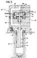
nozzle 50 having a restricted diameter, with anannular adapter 45 for it housed in thecavity 44. Figure 5 shows another example, in which a larger-diameter nozzle is fitted without an annular adapter. At the junction area between the outlet aperture of thefeeder duct 38 and thetube 52 of the nozzle, atubular seal element 53 is arranged, which in the preferred embodiment is partially housed in a cavity 54 formed in thelower body 32. Atubular seal element 55, similar to the seal element 54, is inserted through thefeeder duct 38 at the interface between thebodies head 30.
Claims (12)
- A heated head (30) for an injector nozzle (50) for moulding plastics material, which incorporates a duct (38) for feeding the material to be injected and resistor means for heating this feeder duct (38); characterised in that it also incorporates a piston element (34) controlled pneumatically to operate a valve needle (35) for the nozzle (50) and in that the piston element (34) has sealing means (43a) made of a material able to withstand the high operating temperatures of the heated head (30).
- A heated head according to Claim 1, characterised in that it includes an inner chamber (33), slidably housing a piston element (34).
- A heated head according to Claim 2, characterised in that the inner chamber (33) is formed by connecting together two complementary bodies (31, 32).
- A heated head according to Claim 1, characterised in that the piston element (34) has axial retaining means (37) for securing the needle (35) axially to the piston element (34).
- A heated head according to Claim 4, characterised in that a cavity (36) is formed in the lower portion of the piston element (34) which on one side forms an undercut (37) for engaging an enlarged portion (35a) of the rod for securing it to the piston.
- A heated head according to Claim 5, characterised in that, on the other side to the undercut (37), the cavity (36) constitutes a free space for allowing the piston element to slide freely transverse the needle when it is necessary to disconnect the needle from the piston element.
- A heated head according to Claim 1, characterised in that the needle (35) is positioned along the central longitudinal axis of the piston element (34).
- A heated head according to Claim 2, characterised in that it includes ducts (41, 42) in communication with the chamber (33) for providing air flows operable to cause the piston element (34) to slide alternately in opposite directions.
- A heated head according to Claim 1, characterised in that a cavity (44) is formed in the lower portion of the head (30) of an appropriate size for housing heated nozzles (50) of different dimensions.
- A heated head according to Claim 1, characterised in that the valve needle (35) is positioned coaxially in the injection duct (51) of the nozzle (50).
- A heated head according to Claim 1, characterised in that the sealing means include at least one annular element (43a) housed in a respective groove (43) formed in a lateral surface of the piston element (34).
- A heated head according to Claim 1, characterised in that the said annular element (43a) is a piston ring of the type used for the pistons of internal combustion engines.
Applications Claiming Priority (2)
| Application Number | Priority Date | Filing Date | Title |
|---|---|---|---|
| ITTO000862 | 2000-09-13 | ||
| IT2000TO000862A IT1320639B1 (en) | 2000-09-13 | 2000-09-13 | HEATED HEAD TO FEED AN INJECTION NOZZLE FOR THE MOLDING OF PLASTIC MATERIALS. |
Publications (2)
| Publication Number | Publication Date |
|---|---|
| EP1188537A2 true EP1188537A2 (en) | 2002-03-20 |
| EP1188537A3 EP1188537A3 (en) | 2003-03-26 |
Family
ID=11458034
Family Applications (1)
| Application Number | Title | Priority Date | Filing Date |
|---|---|---|---|
| EP01121814A Withdrawn EP1188537A3 (en) | 2000-09-13 | 2001-09-11 | A heated head for feeding an injector nozzle for moulding plastics materials |
Country Status (2)
| Country | Link |
|---|---|
| EP (1) | EP1188537A3 (en) |
| IT (1) | IT1320639B1 (en) |
Cited By (8)
| Publication number | Priority date | Publication date | Assignee | Title |
|---|---|---|---|---|
| US6769901B2 (en) | 2000-04-12 | 2004-08-03 | Mold-Masters Limited | Injection nozzle system for an injection molding machine |
| US6921259B2 (en) | 2002-02-21 | 2005-07-26 | Mold-Masters Limited | Valve pin guide for a valve-gated nozzle |
| US7025585B2 (en) | 2002-04-12 | 2006-04-11 | Gellert Jobst U | Mold gate insert with a thermal barrier |
| US7025586B2 (en) | 2002-07-30 | 2006-04-11 | Mold-Masters Limited | Valve pin guidance and alignment system for an injection molding apparatus |
| US7189071B2 (en) | 2003-02-12 | 2007-03-13 | Mold-Masters Limited | Telescopic manifold nozzle seal |
| US7780434B2 (en) | 2001-10-03 | 2010-08-24 | Mold-Masters (2007) Limited | Nozzle for an injection molding apparatus |
| US7874833B2 (en) | 2009-05-03 | 2011-01-25 | Mold-Masters (2007) Limited | Injection molding runner apparatus having pressure seal |
| CN104085089A (en) * | 2014-06-16 | 2014-10-08 | 苏州好特斯模具有限公司 | Valve needle guide sleeve |
Citations (3)
| Publication number | Priority date | Publication date | Assignee | Title |
|---|---|---|---|---|
| US4832593A (en) * | 1988-01-25 | 1989-05-23 | Husky Injection Molding Systems Ltd. | Large nozzle for hot runner mold |
| FR2641227A1 (en) * | 1988-12-30 | 1990-07-06 | Leonard Roland | Mould nozzle with controlled closure, for injecting plastic |
| EP0920970A1 (en) * | 1997-11-18 | 1999-06-09 | Dynisco Hotrunners Canada, Inc. | Apparatus for controlling plastic melt flow in injection molding machines |
-
2000
- 2000-09-13 IT IT2000TO000862A patent/IT1320639B1/en active
-
2001
- 2001-09-11 EP EP01121814A patent/EP1188537A3/en not_active Withdrawn
Patent Citations (3)
| Publication number | Priority date | Publication date | Assignee | Title |
|---|---|---|---|---|
| US4832593A (en) * | 1988-01-25 | 1989-05-23 | Husky Injection Molding Systems Ltd. | Large nozzle for hot runner mold |
| FR2641227A1 (en) * | 1988-12-30 | 1990-07-06 | Leonard Roland | Mould nozzle with controlled closure, for injecting plastic |
| EP0920970A1 (en) * | 1997-11-18 | 1999-06-09 | Dynisco Hotrunners Canada, Inc. | Apparatus for controlling plastic melt flow in injection molding machines |
Cited By (9)
| Publication number | Priority date | Publication date | Assignee | Title |
|---|---|---|---|---|
| US6769901B2 (en) | 2000-04-12 | 2004-08-03 | Mold-Masters Limited | Injection nozzle system for an injection molding machine |
| US7780434B2 (en) | 2001-10-03 | 2010-08-24 | Mold-Masters (2007) Limited | Nozzle for an injection molding apparatus |
| US7891969B2 (en) | 2001-10-03 | 2011-02-22 | Mold-Masters (2007) Limited | Injection molding nozzle |
| US6921259B2 (en) | 2002-02-21 | 2005-07-26 | Mold-Masters Limited | Valve pin guide for a valve-gated nozzle |
| US7025585B2 (en) | 2002-04-12 | 2006-04-11 | Gellert Jobst U | Mold gate insert with a thermal barrier |
| US7025586B2 (en) | 2002-07-30 | 2006-04-11 | Mold-Masters Limited | Valve pin guidance and alignment system for an injection molding apparatus |
| US7189071B2 (en) | 2003-02-12 | 2007-03-13 | Mold-Masters Limited | Telescopic manifold nozzle seal |
| US7874833B2 (en) | 2009-05-03 | 2011-01-25 | Mold-Masters (2007) Limited | Injection molding runner apparatus having pressure seal |
| CN104085089A (en) * | 2014-06-16 | 2014-10-08 | 苏州好特斯模具有限公司 | Valve needle guide sleeve |
Also Published As
| Publication number | Publication date |
|---|---|
| ITTO20000862A0 (en) | 2000-09-13 |
| IT1320639B1 (en) | 2003-12-10 |
| EP1188537A3 (en) | 2003-03-26 |
| ITTO20000862A1 (en) | 2002-03-13 |
Similar Documents
| Publication | Publication Date | Title |
|---|---|---|
| US5632467A (en) | Valve needle for an electromagnetically actuated valve | |
| US4010903A (en) | Nozzle for injection molding of thermoplastics | |
| DE102005052255B4 (en) | Fuel injector | |
| EP1188537A2 (en) | A heated head for feeding an injector nozzle for moulding plastics materials | |
| JP4606605B2 (en) | Fuel injection valve for internal combustion engine | |
| CN1985087A (en) | Fuel injection valve | |
| CA2284561C (en) | Injection molding shut-off bushing with separate material flow path | |
| CA2193565A1 (en) | Heated needle-locking nozzle | |
| JPH11514713A (en) | Compact fuel injector mover valve assembly | |
| DE102005052252A1 (en) | Fuel injecting valve for fuel injection systems of internal-combustion engines, has sensitive actuator whereby components forming valve housing are molded by means of metal injection molding | |
| KR102569254B1 (en) | Axial fluid injection nozzle with vent valve | |
| KR100732791B1 (en) | Actuating fluid delivery system for a fuel injector | |
| KR102303418B1 (en) | Nozzle body for fuel injectors | |
| JPH02256980A (en) | Solenoid valve | |
| US20160237963A1 (en) | Connector and manufacturing process for the same | |
| EP0058462A1 (en) | Closure system | |
| WO2007143808A1 (en) | Device for preventing leakage in the field of injection molding | |
| US5141210A (en) | Longitudinally adjustable gas spring | |
| US4088271A (en) | Needle-valve for hot runner injection moulding | |
| US6743009B1 (en) | Device for injecting material in a plastic state into a moulding cavity | |
| US7001561B2 (en) | Right angle tube connector | |
| CN100381736C (en) | Fast coupling unit with integrated check valve | |
| US6357676B1 (en) | Fuel injection valve | |
| CZ285342B6 (en) | Injection nozzle used in injection moulding process | |
| US5209199A (en) | Control apparatus for turning off an internal combustion engine |
Legal Events
| Date | Code | Title | Description |
|---|---|---|---|
| PUAI | Public reference made under article 153(3) epc to a published international application that has entered the european phase |
Free format text: ORIGINAL CODE: 0009012 |
|
| AK | Designated contracting states |
Kind code of ref document: A2 Designated state(s): AT BE CH CY DE DK ES FI FR GB GR IE IT LI LU MC NL PT SE TR |
|
| AX | Request for extension of the european patent |
Free format text: AL;LT;LV;MK;RO;SI |
|
| PUAL | Search report despatched |
Free format text: ORIGINAL CODE: 0009013 |
|
| AK | Designated contracting states |
Kind code of ref document: A3 Designated state(s): AT BE CH CY DE DK ES FI FR GB GR IE IT LI LU MC NL PT SE TR Designated state(s): AT BE CH CY DE DK ES FI FR GB GR IE IT LI LU MC NL PT SE TR |
|
| AX | Request for extension of the european patent |
Extension state: AL LT LV MK RO SI |
|
| AKX | Designation fees paid | ||
| REG | Reference to a national code |
Ref country code: DE Ref legal event code: 8566 |
|
| STAA | Information on the status of an ep patent application or granted ep patent |
Free format text: STATUS: THE APPLICATION IS DEEMED TO BE WITHDRAWN |
|
| 18D | Application deemed to be withdrawn |
Effective date: 20030927 |