EP1188977A1 - Hose fitting - Google Patents
Hose fitting Download PDFInfo
- Publication number
- EP1188977A1 EP1188977A1 EP00120453A EP00120453A EP1188977A1 EP 1188977 A1 EP1188977 A1 EP 1188977A1 EP 00120453 A EP00120453 A EP 00120453A EP 00120453 A EP00120453 A EP 00120453A EP 1188977 A1 EP1188977 A1 EP 1188977A1
- Authority
- EP
- European Patent Office
- Prior art keywords
- hose
- connecting pipe
- pipe
- connection
- oval
- Prior art date
- Legal status (The legal status is an assumption and is not a legal conclusion. Google has not performed a legal analysis and makes no representation as to the accuracy of the status listed.)
- Withdrawn
Links
Images

Classifications
-
- F—MECHANICAL ENGINEERING; LIGHTING; HEATING; WEAPONS; BLASTING
- F16—ENGINEERING ELEMENTS AND UNITS; GENERAL MEASURES FOR PRODUCING AND MAINTAINING EFFECTIVE FUNCTIONING OF MACHINES OR INSTALLATIONS; THERMAL INSULATION IN GENERAL
- F16L—PIPES; JOINTS OR FITTINGS FOR PIPES; SUPPORTS FOR PIPES, CABLES OR PROTECTIVE TUBING; MEANS FOR THERMAL INSULATION IN GENERAL
- F16L33/00—Arrangements for connecting hoses to rigid members; Rigid hose connectors, i.e. single members engaging both hoses
- F16L33/30—Arrangements for connecting hoses to rigid members; Rigid hose connectors, i.e. single members engaging both hoses comprising parts inside the hoses only
Definitions
- the invention relates to a connecting pipe for a hose according to the Preamble of claim 1.
- Such connecting pipes are suitable in fluid technology for connecting a Hose to a device, for example to a fluidic drive or to a Pressure sensor or also for connecting hoses.
- a connecting pipe of this type is known (US 4,603,890), which has frustoconical steps through which an elastic hose is held.
- the connection between the hose and the connecting pipe can be sealed with a sealing ring and secured with a clamp or clamp become.
- the known connecting pipes have the disadvantage that the connection between a hose and the connecting pipe is difficult to solve when the hose should not be damaged when loosening, since the frustoconical steps prevent easy disconnection of the hose, which is actually their job equivalent. Furthermore, the geometry is within relatively narrow limits To match the inside diameter and the elasticity of the hoses to be connected, which is often difficult in practice when different products are connected to a certain device.
- the invention has for its object a connecting pipe for To propose hose connections that can be detached multiple times without much effort, without causing an inadmissible material wear.
- Fig. 1, 1 means a connection pipe for a flexible, not shown Hose, which is used to create an easily detachable connection between the Hose and the connecting pipe 1 in the direction of an arrow R on the Connection pipe 1 is slidable.
- the connecting pipe 1 has one in a pipe axis 2 extending passage 3 for a fluid.
- the connecting pipe 1 are perpendicular to the tube axis
- Cross-sectional areas of the connecting pipe 1 are oval on the outside.
- the oval Cross-sectional areas therefore have a large outer diameter d2 and one small outer diameter d1.
- a certain area 4 of the connecting pipe 1, which is used to slip the Hose is provided, is advantageously at least one acting as a barb Level 5.1, 5.2, 5.3, 5.4, 5.5, 5.6 trained, which each advantageously take the form of a Have a truncated cone or a truncated paraboloid.
- the outer shape of the connecting pipe 1 in the region 4 is basically conical executed.
- An outer diameter d2 and / or d1 of the connecting pipe 1 takes So over the certain area 4, which is provided for slipping on the hose is, in the direction R, in which the hose when connecting via the Connection pipe 4 is slidable, essentially, provided that the possibly executed Levels 5.1, 5.2, 5.3, 5.4, 5.5, 5.6 are disregarded in this consideration.
- the connecting pipe 1 serves as a line section with a closed cross section, which is particularly suitable for conveying fluids. It goes without saying that with suitable dimensions of the passage 3 also solid materials, for example a granulate through which the connecting pipe 1 can be conveyed.
- the connecting pipe 1 is particularly versatile in fluid technology. Depending on intended use, one end 10 of the connecting pipe 1 is functional designed by, for example, a thread or a flange for attaching the Connection tube 1 is formed on a device. It goes without saying that that Connection tube 1 but also advantageously in one piece in a housing part or on a facility can be trained.
- a device 15 has two copies of the oval connecting pipe 1.
- the Device 15 is, for example, a sensor for measuring a pressure difference between two fluids, which can be supplied to the device 15 in flexible hoses 16 and 17.
- the two tubes 16 and 17 are preferably round and are on the oval Connection pipes 1 pushed on.
- two or more oval connecting pipes 1 are as Hose connecting elements can be joined, two versions of the Connection pipe 1 - as shown in Fig. 4 - as a quick coupling for two Hoses 18 and 19, three versions of the connecting pipe 1 as a T-shaped or Y-shaped Hose connection element or four versions of the connecting pipe 1 as a cross connector for four hoses can be joined to some To name examples.
- the oval cross-sectional areas of the Connecting pipe 1 initially cause a connection in area 4 round hose a deformation, which when rotating the hose around the Pipe axis 2 is at least partially plastic, so that the hose after a slight rotation around the tube axis 2 without problems against the drawn Have the direction of arrow R removed from the connecting pipe 1.
- the outer shape of said oval cross-sectional areas of the connecting pipe 1 can vary within relatively wide limits, the limits essentially differing from the Deformability and the inner diameter of the hose, the expected pressure of the Fluids and the required security depend. Good functionality for hoses with an inner diameter of about 4 mm and a pressure of up to 6 bar, if the oval cross-sectional areas are elliptical and the ratio of the small outer diameter d1 to the large outer diameter d2 is approximately 3: 4.
- connection between the hose and the connecting pipe 1 additionally sealed with a sealing ring and with a clamp or clamp secured.
- An embodiment of the oval connecting pipe 1 according to the invention is not necessarily constructed symmetrically to the passage channel 3.
- the passage channel 3 lies on an axis 12, which probably according to a first side view in Fig. 2 symmetrically between Straight lines e1 and e2 shown in dashed lines, which the area 4 over the envelop larger outer diameter d2.
- the axis 12 is not dashed symmetrically between others straight lines shown e3 and e4, which the area 4 over the smaller outer Wrap in diameter d1.
Abstract
Description
Die Erfindung bezieht sich auf ein Anschlussrohr für einen Schlauch gemäss dem
Oberbegriff des Anspruchs 1.The invention relates to a connecting pipe for a hose according to the
Preamble of
Solche Anschlussrohre eignen sich in der Fluidtechnik zum Anschliessen eines Schlauches an ein Gerät, beispielsweise an einen fluidischen Antrieb oder an einen Drucksensor oder auch zum Verbinden von Schläuchen.Such connecting pipes are suitable in fluid technology for connecting a Hose to a device, for example to a fluidic drive or to a Pressure sensor or also for connecting hoses.
Es ist ein Anschlussrohr dieser Art bekannt (US 4,603,890), welches kegelstumpfförmige Stufen aufweist durch welche ein elastischer Schlauch festgehalten wird. Die Verbindung zwischen dem Schlauch und dem Anschlussrohr kann mit einem Dichtungsring abgedichtet und mit einer Schelle oder Bride gesichert werden.A connecting pipe of this type is known (US 4,603,890), which has frustoconical steps through which an elastic hose is held. The connection between the hose and the connecting pipe can be sealed with a sealing ring and secured with a clamp or clamp become.
Es ist auch bekannt (EP 959 289 A1), am Anschlussrohr einen Flansch auszubilden, der als Anschlag für einen aufgeschobenen Schlauch einsetzbar ist.It is also known (EP 959 289 A1) to form a flange on the connecting pipe, which can be used as a stop for a hose that has been pushed on.
Die bekannten Anschlussrohre haben den Nachteil, dass die Verbindung zwischen einem Schlauch und dem Anschlussrohr nur schlecht lösbar ist, wenn der Schlauch beim Lösen nicht beschädigt werden soll, da die kegelstumpfförmigen Stufen ein einfaches Abziehen des Schlauchs verhindern, was ja eigentlich auch ihrer Aufgabe entspricht. Im weiteren ist die Geometrie in relativ engen Grenzen auf den Innendurchmesser und die Elastizität der anzuschliessenden Schläuche abzustimmen, was in der Praxis of schwierig ist, wenn unterschiedliche Produkte für den Anschluss an ein gewisses Gerät in Frage kommen.The known connecting pipes have the disadvantage that the connection between a hose and the connecting pipe is difficult to solve when the hose should not be damaged when loosening, since the frustoconical steps prevent easy disconnection of the hose, which is actually their job equivalent. Furthermore, the geometry is within relatively narrow limits To match the inside diameter and the elasticity of the hoses to be connected, which is often difficult in practice when different products are connected to a certain device.
Der Erfindung liegt die Aufgabe zugrunde, ein Anschlussrohr für Schlauchverbindungen vorzuschlagen, die ohne viel Aufwand mehrfach lösbar sind, ohne dass dabei der ein unzulässiger Materialverschleiss verursacht wird.The invention has for its object a connecting pipe for To propose hose connections that can be detached multiple times without much effort, without causing an inadmissible material wear.
Die genannte Aufgabe wird erfindungsgemäss durch die Merkmale des Anspruchs 1
gelöst. Weiterbildungen der Erfindung ergeben sich aus den abhängigen Ansprüchen.According to the invention, this object is achieved by the features of
Nachfolgend werden Ausführungsbeispiele der Erfindung anhand der Zeichnung näher erläutert. Exemplary embodiments of the invention are described in more detail below with reference to the drawing explained.
Es zeigen:
- Fig. 1
- ein Anschlussrohr in einer teilweise geschnittener Seitenansicht, einer teilweise geschnittenen Draufsicht und einer weiteren Seitenansicht,
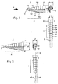
- Fig. 2
- eine Ausführungsvariante des Anschlussrohres in einer teilweise geschnittener Seitenansicht, einer teilweise geschnittenen Draufsicht und einer weiteren Seitenansicht,
- Fig. 3
- ein Gerät der Fluidtechnik mit zwei Exemplaren des Anschlussrohrs, und
- Fig. 4
- ein Verbindungselement der Fluidtechnik.
- Fig. 1
- a connecting pipe in a partially sectioned side view, a partially sectioned top view and a further side view,
- Fig. 2
- 1 shows a variant of the connecting pipe in a partially sectioned side view, a partially sectioned top view and a further side view,
- Fig. 3
- a device of fluid technology with two copies of the connecting pipe, and
- Fig. 4
- a connecting element of fluid technology.
In der Fig. 1 bedeutet 1 ein Anschlussrohr für einen nicht dargestellten flexiblen
Schlauch, welcher zur Herstellung einer leicht lösbaren Verbindung zwischen dem
Schlauch und dem Anschlussrohr 1 in der Richtung eines Pfeils R auf das
Anschlussrohr 1 schiebbar ist. Das Anschlussrohr 1 weist einen in einer Rohrachse 2
verlaufenden Durchlasskanal 3 für ein Fluid auf.In Fig. 1, 1 means a connection pipe for a flexible, not shown
Hose, which is used to create an easily detachable connection between the
Hose and the connecting
Gemäss der vorliegenden Erfindung sind senkrecht zur Rohrachse 2 liegende
Querschnittflächen des Anschlussrohrs 1 aussen oval begrenzt. Die ovalen
Querschnittsflächen weisen also einen grossen äusseren Durchmesser d2 und einen
kleinen äusseren Durchmesser d1 auf.According to the present invention, 2 are perpendicular to the tube axis
Cross-sectional areas of the connecting
In einem gewissen Bereich 4 des Anschlussrohrs 1, der zum Überstülpen des
Schlauchs vorgesehen ist, ist mit Vorteil wenigstens eine als Widerhaken wirkende
Stufe 5.1, 5.2, 5.3, 5.4, 5.5, 5.6 ausgebildet, welche mit Vorteil je die Form eines
Kegelstumpfs oder eines abgestumpften Paraboloids aufweisen.In a
Damit das Anschlussrohr 1 für verschiedene Schlauchdurchmesser verwendbar ist, ist
die äussere Form des Anschlussrohres 1 im Bereich 4 grundsätzlich konisch
ausgeführt. Ein äusserer Durchmesser d2 und/oder d1 des Anschlussrohrs 1 nimmt
also über den gewissen Bereich 4, der zum Überstülpen des Schlauchs vorgesehen
ist, in der Richtung R, in welcher der Schlauch beim Anschliessen über das
Anschlussrohr 4 schiebbar ist, im wesentlichen zu, sofern die allfällig ausgeführten
Stufen 5.1, 5.2, 5.3, 5.4, 5.5, 5.6 bei dieser Betrachtung ausser Acht gelassen werden.So that the connecting
Das Anschlussrohr 1 dient als Leitungsstück mit geschlossenem Querschnitt, welches
besonders geeignet ist für das Fördern von Fluiden. Es versteht sich von selbst, dass
bei geeigneter Dimensionierung des Durchlasskanals 3 auch feste Stoffe,
beispielsweise ein Granulat, durch das Anschlussrohr 1 förderbar sind.The connecting
Das Anschlussrohr 1 ist insbesondere in der Fluidtechnik vielseitig einsetzbar. Je nach
vorgesehenem Einsatz ist ein Ende 10 des Anschlussrohrs 1 funktionsgerecht
gestaltet, indem beispielsweise ein Gewinde oder ein Flansch zum Befestigen des
Anschlussrohrs 1 an einem Gerät ausgebildet ist. Es versteht sich von selbst, dass das
Anschlussrohr 1 aber auch vorteilhaft direkt einstückig in einem Gehäuseteil oder an
einer Einrichtung ausgebildet werden kann.The connecting
In der Fig. 3 weist ein Gerät 15 zwei Exemplare des ovalen Anschlussrohrs 1 auf. Das
Gerät 15 ist beispielsweise ein Sensor zum Messen einer Druckdifferenz zwischen
zwei Fluiden, welche in flexiblen Schläuchen 16 und 17 dem Gerät 15 zuführbar sind.
Die beiden Schläuche 16 und 17 sind vorzugsweise rund und werden auf die ovalen
Anschlussrohre 1 aufgeschoben.In Fig. 3, a
Im weiteren sind zwei oder mehrere ovale Anschlussrohre 1 als
Schlauchverbindungselemente zusammenfügbar, wobei 2 Ausführungen des
Anschlussrohrs 1 - wie in der Fig. 4 dargestellt - als Schnellkupplung für zwei
Schläuche 18 und 19, drei Ausführungen des Anschlussrohrs 1 als T-förmiges oder Y-förmiges
Schlauchverbindungselement oder vier Ausführungen des Anschlussrohrs 1
als Kreuz-Verbindungselement für vier Schläuche zusammenfügbar sind, um einige
Beispiele zu nennen.Furthermore, two or more oval connecting
Die senkrecht zur Rohrachse 2 liegenden ovalen Querschnittflächen des
Anschlussrohrs 1 bewirken bei einem im Bereich 4 angeschlossenen ursprünglich
runden Schlauch eine Verformung, welche bei einem Verdrehen des Schlauchs um die
Rohrachse 2 mindestens teilweise plastisch ist, so dass sich der Schlauch nach einer
leichten Drehung um die Rohrachse 2 problemlos entgegen der eingezeichneten
Richtung des Pfeils R vom Anschlussrohr 1 entfernen lässt.The oval cross-sectional areas of the
Connecting
Die äussere Form der besagten ovalen Querschnittflächen des Anschlussrohrs 1 kann
in relativ weiten Grenzen variieren, wobei die Grenzen im Wesentlichen von der
Verformbarkeit und dem Innendurchmesser des Schlauchs, dem erwarteten Druck des
Fluids und der erforderlichen Sicherheit abhängen. Gute Funktionalität für Schläuche
mit einem Innendurchmesser von etwa 4 mm und einem Druck bis 6 bar ist erreichbar,
wenn die ovalen Querschnittflächen ellipsenförmig sind und das Verhältnis des kleinen
äusseren Durchmessers d1 zum grossen äusseren Durchmesser d2 etwa 3:4 ist. The outer shape of said oval cross-sectional areas of the connecting
Sofern relativ weiche und gut verformbare Schläuche eingesetzt werden, kann das Verhältnis des kleinen äusseren Durchmessers d1 zum grossen äusseren Durchmesser d2 bis etwa 1:2 verkleinert und bei relativ kleinem Druck im Fluid bis etwa 9:10 vergrössert werden.If relatively soft and easily deformable hoses are used, this can Ratio of the small outer diameter d1 to the large outer Diameter d2 reduced to about 1: 2 and at a relatively low pressure in the fluid about 9:10.
Eine aus dem vorgeschlagenen ovalen Anschlussrohr 2 und dem flexiblen Schlauch
mit dem runden Innenquerschnitt gebildete Schlauchverbindung ist ohne viel Aufwand
mehrfach lösbar, ohne dass dabei ein unzulässiger Materialverschleiss verursacht
würde.One from the proposed oval connecting
Bei Bedarf ist die Verbindung zwischen dem Schlauch und dem Anschlussrohr 1
zusätzlich mit einem Dichtungsring abgedichtet und mit einer Schelle oder Bride
gesichert.If necessary, the connection between the hose and the connecting
Eine erfindungsgemässe Ausführung des ovalen Anschlussrohrs 1 ist nicht
notwendigerweise symmetrisch zum Durchlasskanal 3 aufgebaut. In einer in der Fig. 2
dargestellten Ausführungsvariante liegt der Durchlasskanal 3 auf einer Achse 12,
welche wohl gemäss einer ersten Seitenansicht in der Fig. 2 symmetrisch zwischen
gestrichelt dargestellten Geraden e1 und e2 liegt, welche den Bereich 4 über den
grösseren äusseren Durchmesser d2 einhüllen. Gemäss einer zweiten Seitenansicht in
der Fig. 2 liegt die Achse 12 jedoch nicht symmetrisch zwischen weiteren gestrichelt
dargestellten Geraden e3 und e4, welche den Bereich 4 über den kleineren äusseren
Durchmesser d1 einhüllen.An embodiment of the oval connecting
Die Ausführungsvariante nach Fig. 2 ermöglicht die Anordnung von zwei
Anschlussrohren 1 relativ nahe nebeneinander, wenn beispielsweise an einem Gerät
zwei Öffnungen für die Anschlussrohre 2 mit geringem Abstand vorgegeben sind.2 enables the arrangement of two
Claims (5)
Priority Applications (2)
| Application Number | Priority Date | Filing Date | Title |
|---|---|---|---|
| EP00120453A EP1188977A1 (en) | 2000-09-19 | 2000-09-19 | Hose fitting |
| DE20017756U DE20017756U1 (en) | 2000-09-19 | 2000-10-17 | Connection pipe for a hose |
Applications Claiming Priority (1)
| Application Number | Priority Date | Filing Date | Title |
|---|---|---|---|
| EP00120453A EP1188977A1 (en) | 2000-09-19 | 2000-09-19 | Hose fitting |
Publications (1)
| Publication Number | Publication Date |
|---|---|
| EP1188977A1 true EP1188977A1 (en) | 2002-03-20 |
Family
ID=8169873
Family Applications (1)
| Application Number | Title | Priority Date | Filing Date |
|---|---|---|---|
| EP00120453A Withdrawn EP1188977A1 (en) | 2000-09-19 | 2000-09-19 | Hose fitting |
Country Status (2)
| Country | Link |
|---|---|
| EP (1) | EP1188977A1 (en) |
| DE (1) | DE20017756U1 (en) |
Cited By (2)
| Publication number | Priority date | Publication date | Assignee | Title |
|---|---|---|---|---|
| CN103083799A (en) * | 2011-11-03 | 2013-05-08 | 江苏康诺医疗器械有限公司 | Multi-diameter section two-way connector |
| DE102013021992A1 (en) | 2013-04-18 | 2014-10-23 | Eagle Actuator Components Gmbh & Co. Kg | Arrangement with a connecting piece and a pipe |
Citations (6)
| Publication number | Priority date | Publication date | Assignee | Title |
|---|---|---|---|---|
| US4597594A (en) * | 1983-09-09 | 1986-07-01 | Chris Kaye Plastics Corp. | Hose connector |
| US4603890A (en) | 1984-12-06 | 1986-08-05 | Robert Huppee | Barbed tubing connector |
| US4875719A (en) * | 1989-01-26 | 1989-10-24 | Mylett Christopher J | Universal hose connector |
| US5165733A (en) * | 1988-02-19 | 1992-11-24 | Sampson Richard K | Apparatus for connecting an elastic hose to a system |
| EP0886096A1 (en) * | 1997-06-19 | 1998-12-23 | FESTO AG & Co | Connection device and fluid distributor with one or more of said connection devices |
| EP0959289A1 (en) | 1998-04-22 | 1999-11-24 | M.G.I. Coutier S.A. | Connecting device for coupling a pipe to an interface |
-
2000
- 2000-09-19 EP EP00120453A patent/EP1188977A1/en not_active Withdrawn
- 2000-10-17 DE DE20017756U patent/DE20017756U1/en not_active Expired - Lifetime
Patent Citations (6)
| Publication number | Priority date | Publication date | Assignee | Title |
|---|---|---|---|---|
| US4597594A (en) * | 1983-09-09 | 1986-07-01 | Chris Kaye Plastics Corp. | Hose connector |
| US4603890A (en) | 1984-12-06 | 1986-08-05 | Robert Huppee | Barbed tubing connector |
| US5165733A (en) * | 1988-02-19 | 1992-11-24 | Sampson Richard K | Apparatus for connecting an elastic hose to a system |
| US4875719A (en) * | 1989-01-26 | 1989-10-24 | Mylett Christopher J | Universal hose connector |
| EP0886096A1 (en) * | 1997-06-19 | 1998-12-23 | FESTO AG & Co | Connection device and fluid distributor with one or more of said connection devices |
| EP0959289A1 (en) | 1998-04-22 | 1999-11-24 | M.G.I. Coutier S.A. | Connecting device for coupling a pipe to an interface |
Cited By (2)
| Publication number | Priority date | Publication date | Assignee | Title |
|---|---|---|---|---|
| CN103083799A (en) * | 2011-11-03 | 2013-05-08 | 江苏康诺医疗器械有限公司 | Multi-diameter section two-way connector |
| DE102013021992A1 (en) | 2013-04-18 | 2014-10-23 | Eagle Actuator Components Gmbh & Co. Kg | Arrangement with a connecting piece and a pipe |
Also Published As
| Publication number | Publication date |
|---|---|
| DE20017756U1 (en) | 2002-02-14 |
Similar Documents
| Publication | Publication Date | Title |
|---|---|---|
| EP3173675B1 (en) | Hose connection | |
| DE3813192C2 (en) | ||
| EP0848201B1 (en) | Connecting device for socket and spigot couplings conveying fluids | |
| EP0170845A1 (en) | Shaped piercing piece for joining a branch pipe | |
| DE3237929A1 (en) | PIPE OR HOSE CONNECTION | |
| DE4109572A1 (en) | COVERING SYSTEM FOR A FLEXIBLE UNDERGROUND PIPE SYSTEM | |
| EP0003746B1 (en) | Plug arrangement | |
| DE10126429B4 (en) | Hose device for transporting fluids | |
| DE60020212T2 (en) | PIPE CONNECTING ELEMENT, ESPECIALLY FOR PLASTIC PIPES | |
| EP0577803B1 (en) | Pipe socket | |
| CH665465A5 (en) | Pipe connection for plastic pipes. | |
| EP3322923B1 (en) | Sanitary line attachment | |
| EP2199652B1 (en) | Device for sealed connection and fixing of a fluid line with another fluid-transporting component | |
| EP1188977A1 (en) | Hose fitting | |
| DE19504698C1 (en) | Drilling sleeve for pipe | |
| EP3452746A1 (en) | Connecting device, in particular in the form of a hose coupling | |
| EP2843283B1 (en) | Suction conveyor system | |
| EP3366851B1 (en) | Universal filling valve set | |
| EP1118811A2 (en) | Flexible pipe with a connector on at least one end | |
| EP1544531A1 (en) | Releasable tube coupling | |
| DE4211959A1 (en) | Connection fitting for metallic pipes - incorporates axial bore with female thread and plane section with sealing groove | |
| DE1536900C3 (en) | Detachable fastening device for filter bodies | |
| WO2005071303A1 (en) | Device for connecting a corrugated pipe to a counterpart | |
| DE19816231C1 (en) | Connection nipple for spray nozzles | |
| DE3518895C2 (en) |
Legal Events
| Date | Code | Title | Description |
|---|---|---|---|
| PUAI | Public reference made under article 153(3) epc to a published international application that has entered the european phase |
Free format text: ORIGINAL CODE: 0009012 |
|
| AK | Designated contracting states |
Kind code of ref document: A1 Designated state(s): AT BE CH CY DE DK ES FI FR GB GR IE IT LI LU MC NL PT SE |
|
| AX | Request for extension of the european patent |
Free format text: AL;LT;LV;MK;RO;SI |
|
| AKX | Designation fees paid | ||
| REG | Reference to a national code |
Ref country code: DE Ref legal event code: 8566 |
|
| STAA | Information on the status of an ep patent application or granted ep patent |
Free format text: STATUS: THE APPLICATION IS DEEMED TO BE WITHDRAWN |
|
| 18D | Application deemed to be withdrawn |
Effective date: 20020921 |