-
The present invention relates to a disc case used
to store media discs, such as compact discs, so-called
CD singles, digital versatile discs, etc.
-
In a disc case that is conventionally used to
store a media disc such as a compact disc, upper and
lower plastic cases are swingably coupled to each other
by means of hinge pivots, in general. A circular boss
(center boss) is formed in the center of the lower case
of the conventional disc case of this type. The disc
is held in a manner such that its recording surface is
floating as its center hole is fitted on the center
boss.
-
Disc cases that are used to store discs containing
musical pieces, literature, etc. require peculiar,
beautiful designs that distinguish those disc contents
from others. If the center boss is formed on the base
plate, as in the conventional disc case, however,
it inevitably restricts the case design.
-
Possibly, a flat base plate without a center boss
may be used for the purpose. In this case, however,
a protective sheet such as a nonwoven fabric must be
used to protect the recording surface of a disc.
Thus, the number of indispensable components increases,
and besides, the protective sheet spoils the beautiful
appearance of the expressly designed base plate.
-
A proposed example of a disc case without a center
boss is formed having an opening in a side face of its
tray. A disc can be loaded into and unloaded from this
disc case through the opening in the lateral direction
of the tray. Conventional automatic disc loaders are
designed so that they can insert the disc into the tray
that is held horizontal from above the tray (in the
thickness direction of the tray). Thus, the existing
automatic disc loaders cannot be applied to disc cases
that require the disc to be inserted in the lateral
direction of the tray.
-
Accordingly, the object of the present invention
is to provide a disc case capable of holding a disc in
a given position on a tray without using a center boss
and preferably of allowing the disc to be loaded into
and unloaded from the tray in the thickness direction
of the disc.
-
The present invention is set out in the
independent claim. Some optional features are set out
in the claims dependent thereto.
-
A disc case according to one embodiment
comprises a tray having a recess to be stored with a
disc, a disc supporting portion formed on a peripheral
wall portion of the recess and capable of supporting
the outer peripheral portion of the disc in a manner
such that the recording surface of the disc is
floating, and spring portions provided near the
peripheral wall portion. Each of the spring portions
preferably may include a protuberance movable between
a projecting position in which it prevents the disc
from slipping out of the recess and a position in which
it allows the disc to be taken out, a spring element
for urging the protuberance toward the projecting
position, and a guide surface adapted to touch the
outer peripheral portion of the disc, thereby bending
the spring element in a direction to allow the
insertion of the disc into the recess, as the disc is
inserted into the recess.
-
When the disc case is stored with the disc, the
outer peripheral portion of the disc touches the
respective guide surfaces of the spring portions.
As the spring elements bend, the outer peripheral of
the disc moves into inside the protuberances, whereby
the disc is set in the recess. The respective
protuberances of the spring portions are restored to
their original projecting position by means of the
elastic force of the spring elements. The outer
peripheral portion of the disc in the recess is
supported by means of the disc supporting portion.
Thus, the recording surface of the disc is slightly
lifted above the base portion of the tray. Besides,
the protuberances prevent the disc from slipping out of
the tray.
-
According to the present invention, the disc can
be held in a given position on the tray with its
recording surface floating without using a center boss.
Since the disc case of the invention uses no center
boss, restrictions on the design of the base portion of
the tray are reduced. Further, the disc can be
inserted into the recess in its thickness direction.
-
According to this invention, each of the spring
portions may include an arm-shaped spring element that
extends along a slot in the tray and can bend around
the opposite ends of the slot. In this case, the
spring elements easily bend in the diametrical
direction of the disc.
-
Preferably, according to this invention, the tray
is formed having an elliptic or oval recess. In taking
out the disc, in this case, the disc can be easily
disengaged from the protuberances by bending the spring
elements in a manner such that its position is slightly
shifted in the major-axis direction of the recess.
-
Preferably, according to this invention, an
opening is formed in a side portion of the tray.
In taking out the disc from the recess, in this case,
a user can push the spring elements by, for example,
slightly shifting the position of the disc with his/her
finger on the outer peripheral portion of the disc at
the opening.
-
According to another embodiment, a recess is
formed in a tray of a disc case. A peripheral wall
portion of the recess is formed having disc supporting
portions that support a disc in a manner such that the
recording surface of the disc is floating. Spring
elements are arranged along slots that are formed in
the peripheral wall portion. Each spring element is
formed having a protuberance and a guide surface. As
the disc is inserted into the recess, the spring
elements bend with their respective guide surfaces
touched by an outer peripheral portion of the disc.
The outer peripheral portion moves into the space
inside the protuberances of the spring elements. When
the disc is in the recess, the protuberances prevent
the disc from slipping out of the recess.
-
The invention can be put into practice in several
ways. Specific embodiments will now be described by
way of example, with reference to the accompanying
drawings in which:-
- FIG. 1 is a perspective view of a disc case
according to a first embodiment of the present
invention;
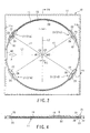
- FIG. 2 is a plan view of a tray of the disc case
shown in FIG. 1;
- FIG. 3 is an enlarged plan view showing part of
the tray shown in FIG. 2;
- FIG. 4 is a sectional view of the tray with a disc
therein, taken along line F4-F4 of FIG. 2;
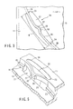
- FIG. 5 is an enlarged perspective view showing
part of the tray shown in FIG. 2;
- FIG. 6 is an enlarged sectional view of a spring
portion shown in FIG. 4;
- FIG. 7 is a perspective view of a disc case
according to a second embodiment of the invention;
- FIG. 8A is a perspective view, partially in
section, showing a spring portion according to a third
embodiment of the invention;
- FIG. 8B is a perspective view, partially in
section, showing a spring portion according to a fourth
embodiment of the invention;
- FIG. 8C is a perspective view, partially in
section, showing a spring portion according to a fifth
embodiment of the invention;
- FIG. 9 is a perspective view, partially in
section, showing a spring portion according to a sixth
embodiment of the invention;
- FIG. 10 is a perspective view, partially in
section, showing a spring portion according to a
seventh embodiment of the invention;
- FIG. 11 is a plan view of a disc case according to
an eighth embodiment of the invention;
- FIG. 12 is a perspective view of a disc case
according to a ninth embodiment of the invention;
- FIG. 13 is a plan view of a tray of the disc case
shown in FIG. 12;
- FIG. 14 is a sectional view of the tray taken
along line F14-F14 of FIG. 13;
- FIG. 15 is a partial sectional view of the disc
case shown in FIG. 1;
- FIGS. 16, 17 and 18 are partial sectional views of
disc cases having differently modified lugs,
individually;
- FIG. 19 is a plan view of a disc case according to
a tenth embodiment of the present invention; and
- FIG. 20 is a plan view of a disc case according to
an eleventh embodiment of the present invention.
-
-
A disc case 10 according to a first embodiment of
the present invention will now be described with
reference to FIGS. 1 to 6.
-
The disc case 10 shown in FIG. 1 comprises a
plastic tray 11 and a lid 13 that is swingably attached
to the tray 11 by means of a hinge portion 12. The
tray 11 is formed having a circular recess 14 that is
shaped corresponding to the external shape of a disc D.
The recess 14 includes a flat base portion 15 and a
peripheral wall portion 16 around the base portion 15.
-
Disc supporting portions 20 are formed on the
peripheral wall portion 16. As shown in FIG. 4, the
supporting portions 20 can carry thereon an outer
peripheral portion D1 of the disc D in the recess 14
in a manner such that a recording surface D2 of the
disc is floating. The supporting portions 20 are
formed in a plurality of positions that are spaced
in the circumferential direction of the recess 14.
The supporting portions 20 may be replaced with
a supporting portion that extends continuously in
the circumferential direction of the recess 14.
-
Spring portions 21 are provided in a plurality of
positions located close to the peripheral wall portion
16 of the recess 14 and spaced in the circumferential
direction of the recess. Since the spring portions 21
have their configuration and function in common, one of
them will be described representatively. As shown in
FIGS. 3 and 5, the spring portion 21 has a slot 22 that
extends in the circumferential direction of the recess
14 and an arm-shaped spring element 25 that extends
along the slot 22 between its opposite ends 23 and 24.
Further, the spring portion 21 has a protuberance 26
formed near the upper end of the middle portion of
the spring element with respect to its longitudinal
direction and a slanting guide surface 27 formed on
the outer side of the protuberance 26.
-
A central portion 30 of the spring element 25 with
respect to its longitudinal direction projects toward
the inner part of the recess 14. The protuberance 26
is formed integrally with the central portion 30 of the
spring element 25. The spring element 25 can bend in
the diametrical direction of the disc D around the
opposite ends 23 and 24 of the slot 22. The spring
elements 25 push the outer peripheral portion D1 of
the disc in the diametrical direction of the disc D,
thereby the disc D is urged towards the center of the
recess 14.
-
The protuberance 26 can move in the direction
indicated by arrow C in FIG. 6. More specifically, the
protuberance 26 can move between a projecting position
B1 in which it prevents the disc D from slipping out
of the recess 14 and a position B2 in which it allows
the disc D to be taken out. The plate shaped spring
element 25 urges the protuberance 26 toward the
projecting position B1.
-
In the case of the tray 11 shown in FIG. 2, the
spring portions 21 are located individually in four
positions at given spaces in the circumferential
direction of the peripheral wall portion 16 of the
recess 14. Among the four spring portions 21, a pair
of spring portions 21a and 21b that are situated nearer
to one side portion 11a of the tray 11 than to the
other side portion 11b adjoin each other at an angle
1 (e.g., 60° or thereabout) narrower than 90° to
each other. Another pair of spring portions 21c and
21d that are situated nearer to the object side portion
11b of the tray 11 also adjoin each other at an angle
2 (e.g., 60° or thereabout) narrower than 90° to
each other. Thus, each spring portion 21 is liable to
bend in the direction indicated by a segment L1 in
FIG. 2.
-
The plane shape of the recess 14 (taken as the
tray 11 is viewed in its thickness direction) is the
shape of an ellipse or oval that has its major axis
extending along the segment L1 (along which each spring
element 25 is liable to bend) and its minor axis
extending along a segment L2 perpendicular to the
segment L1. In this embodiment, the major axis is
longer than the minor axis by a dimension ΔL of
several millimeters.
-
In FIG. 2, the respective centers of circular arcs
R1 and R2 that pass individually through the respective
distal ends of the protuberances 26 are represented by
C1 and C2, respectively. The distances (radii of
curvature) from the centers C1 and C2 to the respective
distal ends of the protuberances 26 are represented by
r1 and r2, respectively. When the spring elements 25
are subjected to no external force (or in a free
state), r1 and r2 are a little shorter than the radius
of the disc D. The guide surface 27 is a slope such
that it projects toward the disc D with distance from
its top to the base portion 15 is increased. As the
disc D is inserted into the recess 14, therefore, each
spring element 25 bends in the direction to allow the
insertion of the disc D with its guide surface 27 in
contact with the outer peripheral portion D1 of the
disc D.
-
The disc case 10 of this embodiment, unlike
a conventional one, uses no center boss, so that its
base portion 15 is substantially flat. If the tray 11
is formed of an optically transparent synthetic resin,
therefore, the backside of the base portion 15 can be
seen from the outside. If a beautifully designed
printed surface is provided on the backside of the tray
11, moreover, the commercial value of the disc case 10
can be enhanced.
-
An opening 40 that opens into the recess 14 is
formed in the one side portion 11a of the tray 11.
The opening 40 enables a user to catch or push the
outer peripheral portion D1 of the disc D with his/her
finger as he/she takes out the disc D from the recess
14. As shown in FIG. 1, lugs 13b are formed inner side
portions 13a of the lid 13. When the lid 13 is put on,
the respective distal ends of the lugs 13b face the
upper surface of the outer peripheral portion D1 of the
disc D.
-
FIGS. 15 to 18 individually show examples of the
shape of each lug 13b. The lugs 13b shown in FIGS. 15
and 16 are reduced in thickness or tapered toward their
respective distal ends 13d so that they have their
respective slopes 13c on the underside. Usually,
respective slopes 13c are slightly apart from the
edge of the outer peripheral portion D1 of the disc.
When the disc D is moved toward the lugs 13b by shock
or the like, the lugs 13b touch only the edge of the
outer peripheral portion D1 of the disc. Accordingly,
if the disc D is turned upside down and the recording
surface D2 of the disc faces on the lugs 13b,
therefore, the recording surface D2 can be prevented
from touching the lugs 13b.
-
The following is a description of the operation of
the disc case 10 according to this embodiment.
-
The disc D can be inserted into the recess 14 in
the thickness direction of the tray 11 (indicated by
arrows A in FIG. 1). When the outer peripheral portion
D1 of the disc D touches the respective guide surfaces
27 of the spring portions 21 as the disc D is inserted
into the recess 14, the spring elements 25 bend so
that the outer peripheral portion D1 of the disc D get
inside the protuberances 26.
-
Thus, the disc D is held in the recess 14, and
the protuberances 26 are returned to their original
projecting position by means of the elastic restoring
force of the spring elements 25. The outer peripheral
portion D1 of the disc D in the recess 14 is supported
by means of the disc supporting portions 20. The
recording surface D2 of the disc D is slightly lifted
above the base portion 15 of the tray 11. Besides,
the protuberances 26 prevent the disc D from slipping
out of the tray 11. When the lid 13 is closed, the
respective distal ends of the lugs 13b face the outer
peripheral portion D1 of the disc D. If a shock acts
on the disc case 10, therefore, the lugs 13b can
further effectively restrain the disc D from slipping
out of the recess 14.
-
The disc case 10 is designed so that the disc D
can be inserted into the recess 14 in its thickness
direction from above. Thus, an automatic loader
that has been used in disc loading operation for
conventional disc cases (cases with a center boss)
can be used without modification. In this automatic
loader, the disc D is kept horizontal by means of
a vacuum suction mechanism or the like. The disc D can
be set in the recess 14 by being simply inserted into
the recess 14 from above the tray 11.
-
The disc case 10 is provided with the spring
elements 25 or plate springs that extend along the
slots 22 in the tray 11. Therefore, each spring
element 25 can enjoy so long an overall length W (shown
in FIG. 3) that it easily bends in the diametrical
direction of the disc D. Further, the flexibility of
each spring element 25 can be adjusted according to
its overall length W. Thus, the spring elements 25 can
be made hard to break, so that their durability can be
improved.
-
The transparent resin for the tray 11, e.g.,
polystyrene, ABS resin, or polyvinyl chloride, etc.
that is doped with no softener, is harder than a resin
that is doped with a softener. As described above,
the spring elements 25 of the disc case 10 can be made
flexible, so that their durability can be improved
despite the use of the relatively hard resin as the
material of the tray 11. However, the material of the
tray 11 may be selected freely, and an opaque resin may
be used for the purpose.
-
In taking out the disc D from the recess 14 of the
disc case 10, the spring portions 21c and 21d can be
bent by pressing the disc D in the major-axis direction
of the recess 14 (indicated by arrow P in FIG. 2).
By doing this, the outer peripheral portion D1 of
the disc D can be easily removed from the respective
protuberances 26 of the spring portions 21a and 21b
that are situated near the opening 40.
-
If the recess 14 has the shape of a perfect
circle, a substantial gap is inevitably created between
the outer peripheral portion D1 of the disc D and the
peripheral wall portion 16 throughout the circumference
of the disc D when the spring portions 21c and 21d are
allowed to bend in the direction of arrow P in FIG. 2.
This gap causes the disc D to shake in the recess 14.
According to this embodiment, however, the recess 14 is
in the shape of a moderate ellipse or oval, so that the
spring elements 25 can fully bend in the direction of
the major axis (segment L1) of the recess 14. The disc
D can be prevented from moving in the direction of the
miner axis (segment L2) of the recess 14. Thus, the
disc D can be restrained from shaking in the recess 14.
Further, the disc D can be easily disengaged from the
protuberances 26 as it is taken out of the recess 14.
-
The side portion 11a of the tray 11 of this
embodiment is formed having the opening 40 on the major
axis (segment L1). In taking out the disc D from the
recess 14, the user softly pushes the disc D in the
direction of arrow P with his/her finger on the outer
peripheral portion D1 of the disc D at the opening 40.
By doing this, the spring portions 21c and 21d can be
bent in the direction of arrow P, and the disc D can be
easily disengaged from the respective protuberances 26
of the spring portions 21a and 21b.
-
FIG. 7 shows a disc case 10A according to a second
embodiment of the invention. The disc case 10A of this
embodiment comprises a tray 11 and a folding cover
member 50 of cardboard. An example of the cover member
50 includes a mount portion 51 fixed to the second
surface of a base portion 15 of the tray 11, a first
cover portion 52 covering the first surface side of the
tray 11, a second cover portion 53 capable of being put
on the second surface side of the mount portion 51,
etc. Since the basic configuration, function, and
effect of the tray 11 of the second embodiment are the
same as those of the tray 11 of the first embodiment,
the common numeral is used to designate the two trays,
and a description of the tray 11 of the second
embodiment is omitted. The cover member 50 may
alternatively be formed of a synthetic resin.
-
In the disc case 10A of the second embodiment,
patterns of desired designs can be beautifully printed
on the cover member 50 by using an existing printing
technique. If an optically transparent synthetic resin
is used for the tray 11, the printed surface of the
mount portion 51 can be seen through the base portion
15. The disc case 10A, unlike a conventional one, uses
no center boss, so that the beautiful printed surface
of the mount portion 51 that is located on the under
surface side of the transparent base portion 15 can be
viewed clearly. Thus, the commercial value of the disc
case 10A is enhanced.
-
The spring elements 25 are expected only to have
elasticity such that they can be deformed by being
pushed by the outer peripheral portion D1 of the disc D
as the disc D is inserted into the recess 14, and that
they can be restored to their original state when the
disc D is held in the recess 14. In either of the
foregoing embodiments, the spring elements 25 may be
molded integrally with or separately from the tray 11.
-
As in the case of a third embodiment shown in
FIG. 8A, for example, the protuberance 26 and the guide
surface 27 of each spring portion 21 may be formed
having a continuous arcuate shape. As in a fourth
embodiment shown in FIG. 8B, moreover, the protuberance
26 of each spring portion 21 may be tapered.
Alternatively, as in a fifth embodiment shown in
FIG. 8C, each spring element 25 may be formed having
a tapered protuberance 26 and a guide surface 27.
These retaining protuberances 26, like the ones
according to the foregoing embodiment, are overhangs
that project toward the inner part of the recess 14.
-
As in the case of a sixth embodiment shown in
FIG. 9, moreover, a protuberance 26 and a guide surface
27 may be formed on the distal end portion of each
spring element 25 that has a U-shaped sheet portion 55.
Alternatively, as in a seventh embodiment shown in
FIG. 10, a protuberance 26 and a guide surface 27 may
be formed on the distal end portion of each spring
element 25 that rises from the base portion 15 of the
tray 11. Thus, the spring portions may be formed
having various shapes.
-
FIG. 11 shows a disc case 10B according to an
eighth embodiment of the invention. Common numerals
are used to designate common portions of the disc cases
10 and 10B of the second and eighth embodiments, and
a description of those portions is omitted. In the
disc case 10B, spring portions 21c and 21d which are
remote from an opening 40 have a shape such that they
can bend deeper in the direction of the segment L1 than
protuberances 26 of those spring portions 21a and 21b
which are situated near the opening 40 can. Besides,
the protuberances 26 of the spring portions 21c and 21d
that are remote from the opening 40 are larger than the
protuberances 26 of the spring portions 21a and 21b
near the opening 40.
-
If a shock acts on the disc case 10B having
these spring portions 21a to 21d, the disc cannot be
easily disengaged from the spring portions 21a to 21d.
In taking out the disc from the tray 11, moreover, the
user can fully bend the spring portions 21c and 21d by
applying force P to an end of the disc with his/her
fingertip 60. Thus, the outer peripheral portion
of the disc D can be easily disengaged from the
protuberances 26 of the spring portions 21a and 21b
that are situated near the opening 40 by bending the
spring portions 21c and 21d that have a longer bending
stroke.
-
FIGS. 12 to 14 show a disc case 10C according to
a ninth embodiment of the invention. As shown in
FIG. 12, a plurality of circular holes 71 are formed
in a base 70 that is formed of cardboard, for example.
Round trays 11' are fitted in the holes 71, individually.
Each tray 11' shares its basic configuration and
function with the tray 11 of the disc case 10B shown in
FIG. 11 except for the following particulars.
-
As shown in FIG. 13, spring portions 21a, 21b and
21c are formed individually in three positions on the
circumference of each tray 11'. Flange portions 75
that engage the upper side of the inner peripheral
surface of each hole 71 in the base 70 and retaining
protuberances 76 that can catch the inner peripheral
surface of the hole 71 are formed on part of the tray
11' in its circumferential direction. The tray 11',
like the tray 11, is formed of an optically transparent
synthetic resin. The base 70 is provided with printed
surfaces 72, on which beautifully designed patterns or
pictures are printed. Among these printed surfaces 72,
those ones which are situated on the backside of the
base portion 15 of the tray 11' can be externally seen
through the transparent base portion 15.
-
FIG. 19 shows a disc case 10 according to a tenth
embodiment of the present invention. This disc case
10 is provided with a pair of retaining protuberances
26a near the opening 40. A spring portion 21 is
formed opposed to the opening 40. A pair of retaining
protuberances 26b is formed near the spring portion 21.
The protuberances 26a closer to the opening 40 are
smaller than the protuberances 26b located near the
spring portion 21.
-
FIG. 20 shows a disc case 10 according to an
eleventh embodiment of the present invention. This
disc case 10 is provided with a pair of protuberance
26a near the opening 40. A protuberance 26b is formed
opposed to the opening 40. A pair of spring portions
21 is formed near the protuberance 26b. Like the
protuberances 26 of the aforesaid embodiments, the
protuberances 26a and 26b are over-hanging so as to
prevent the disc from slipping out of the recess 14.
-
In connection with the foregoing embodiments, the
trays having the recess 14 with an elliptic or oval
plane shape have been described as preferred examples.
However, the present invention is also applicable
to trays with various other shapes. It is to be
understood that the invention is applicable to a disc
case using a tray that has a substantially perfectly
circular recess, for example.
-
In carrying out the present invention, the
material and transparency of the trays may be selected
freely, and in short, it is necessary only that the
trays be shaped corresponding to media discs to be
stored therein. It is to be understood that the
respective configurations of the spring elements,
protuberances, etc. and the number and location of
the spring portions, as well as the respective
configurations of the recess and the disc supporting
portion(s), may be suitably changed or modified by one
skilled in the art without departing from the scope
of the invention.