EP1193107A1 - Display device - Google Patents
Display device Download PDFInfo
- Publication number
- EP1193107A1 EP1193107A1 EP00921049A EP00921049A EP1193107A1 EP 1193107 A1 EP1193107 A1 EP 1193107A1 EP 00921049 A EP00921049 A EP 00921049A EP 00921049 A EP00921049 A EP 00921049A EP 1193107 A1 EP1193107 A1 EP 1193107A1
- Authority
- EP
- European Patent Office
- Prior art keywords
- operating
- displaying
- display
- display apparatus
- console box
- Prior art date
- Legal status (The legal status is an assumption and is not a legal conclusion. Google has not performed a legal analysis and makes no representation as to the accuracy of the status listed.)
- Granted
Links
- 230000000007 visual effect Effects 0.000 claims description 31
- 230000002093 peripheral effect Effects 0.000 claims description 3
- 230000007246 mechanism Effects 0.000 abstract description 12
- 230000000694 effects Effects 0.000 abstract description 7
- 238000010586 diagram Methods 0.000 description 50
- 238000009434 installation Methods 0.000 description 27
- 238000000034 method Methods 0.000 description 13
- 230000006872 improvement Effects 0.000 description 11
- 230000033001 locomotion Effects 0.000 description 10
- 238000005516 engineering process Methods 0.000 description 7
- 230000004044 response Effects 0.000 description 5
- 238000012795 verification Methods 0.000 description 4
- 230000005540 biological transmission Effects 0.000 description 3
- 230000008859 change Effects 0.000 description 3
- 239000000463 material Substances 0.000 description 3
- 238000010276 construction Methods 0.000 description 2
- 238000013461 design Methods 0.000 description 2
- 238000001514 detection method Methods 0.000 description 2
- 230000002265 prevention Effects 0.000 description 2
- 238000012545 processing Methods 0.000 description 2
- 238000009835 boiling Methods 0.000 description 1
- 238000004891 communication Methods 0.000 description 1
- 239000011521 glass Substances 0.000 description 1
- 239000011347 resin Substances 0.000 description 1
- 229920005989 resin Polymers 0.000 description 1
- 238000001228 spectrum Methods 0.000 description 1
- 230000007480 spreading Effects 0.000 description 1
- XLYOFNOQVPJJNP-UHFFFAOYSA-N water Substances O XLYOFNOQVPJJNP-UHFFFAOYSA-N 0.000 description 1
Images


Classifications
-
- G—PHYSICS
- G09—EDUCATION; CRYPTOGRAPHY; DISPLAY; ADVERTISING; SEALS
- G09F—DISPLAYING; ADVERTISING; SIGNS; LABELS OR NAME-PLATES; SEALS
- G09F9/00—Indicating arrangements for variable information in which the information is built-up on a support by selection or combination of individual elements
-
- B—PERFORMING OPERATIONS; TRANSPORTING
- B60—VEHICLES IN GENERAL
- B60K—ARRANGEMENT OR MOUNTING OF PROPULSION UNITS OR OF TRANSMISSIONS IN VEHICLES; ARRANGEMENT OR MOUNTING OF PLURAL DIVERSE PRIME-MOVERS IN VEHICLES; AUXILIARY DRIVES FOR VEHICLES; INSTRUMENTATION OR DASHBOARDS FOR VEHICLES; ARRANGEMENTS IN CONNECTION WITH COOLING, AIR INTAKE, GAS EXHAUST OR FUEL SUPPLY OF PROPULSION UNITS IN VEHICLES
- B60K35/00—Arrangement of adaptations of instruments
-
- B60K35/22—
-
- B60K35/53—
-
- B—PERFORMING OPERATIONS; TRANSPORTING
- B60—VEHICLES IN GENERAL
- B60R—VEHICLES, VEHICLE FITTINGS, OR VEHICLE PARTS, NOT OTHERWISE PROVIDED FOR
- B60R11/00—Arrangements for holding or mounting articles, not otherwise provided for
- B60R11/02—Arrangements for holding or mounting articles, not otherwise provided for for radio sets, television sets, telephones, or the like; Arrangement of controls thereof
- B60R11/0211—Arrangements for holding or mounting articles, not otherwise provided for for radio sets, television sets, telephones, or the like; Arrangement of controls thereof for record carriers apparatus, e.g. video recorders, tape players or CD players
-
- B—PERFORMING OPERATIONS; TRANSPORTING
- B60—VEHICLES IN GENERAL
- B60R—VEHICLES, VEHICLE FITTINGS, OR VEHICLE PARTS, NOT OTHERWISE PROVIDED FOR
- B60R11/00—Arrangements for holding or mounting articles, not otherwise provided for
- B60R11/02—Arrangements for holding or mounting articles, not otherwise provided for for radio sets, television sets, telephones, or the like; Arrangement of controls thereof
- B60R11/0229—Arrangements for holding or mounting articles, not otherwise provided for for radio sets, television sets, telephones, or the like; Arrangement of controls thereof for displays, e.g. cathodic tubes
- B60R11/0235—Arrangements for holding or mounting articles, not otherwise provided for for radio sets, television sets, telephones, or the like; Arrangement of controls thereof for displays, e.g. cathodic tubes of flat type, e.g. LCD
-
- B—PERFORMING OPERATIONS; TRANSPORTING
- B60—VEHICLES IN GENERAL
- B60R—VEHICLES, VEHICLE FITTINGS, OR VEHICLE PARTS, NOT OTHERWISE PROVIDED FOR
- B60R11/00—Arrangements for holding or mounting articles, not otherwise provided for
- B60R11/02—Arrangements for holding or mounting articles, not otherwise provided for for radio sets, television sets, telephones, or the like; Arrangement of controls thereof
- B60R11/0264—Arrangements for holding or mounting articles, not otherwise provided for for radio sets, television sets, telephones, or the like; Arrangement of controls thereof for control means
-
- G—PHYSICS
- G11—INFORMATION STORAGE
- G11B—INFORMATION STORAGE BASED ON RELATIVE MOVEMENT BETWEEN RECORD CARRIER AND TRANSDUCER
- G11B31/00—Arrangements for the associated working of recording or reproducing apparatus with related apparatus
-
- G—PHYSICS
- G11—INFORMATION STORAGE
- G11B—INFORMATION STORAGE BASED ON RELATIVE MOVEMENT BETWEEN RECORD CARRIER AND TRANSDUCER
- G11B33/00—Constructional parts, details or accessories not provided for in the other groups of this subclass
-
- G—PHYSICS
- G11—INFORMATION STORAGE
- G11B—INFORMATION STORAGE BASED ON RELATIVE MOVEMENT BETWEEN RECORD CARRIER AND TRANSDUCER
- G11B33/00—Constructional parts, details or accessories not provided for in the other groups of this subclass
- G11B33/02—Cabinets; Cases; Stands; Disposition of apparatus therein or thereon
-
- B—PERFORMING OPERATIONS; TRANSPORTING
- B60—VEHICLES IN GENERAL
- B60R—VEHICLES, VEHICLE FITTINGS, OR VEHICLE PARTS, NOT OTHERWISE PROVIDED FOR
- B60R11/00—Arrangements for holding or mounting articles, not otherwise provided for
- B60R2011/0001—Arrangements for holding or mounting articles, not otherwise provided for characterised by position
- B60R2011/0003—Arrangements for holding or mounting articles, not otherwise provided for characterised by position inside the vehicle
- B60R2011/0005—Dashboard
-
- B—PERFORMING OPERATIONS; TRANSPORTING
- B60—VEHICLES IN GENERAL
- B60R—VEHICLES, VEHICLE FITTINGS, OR VEHICLE PARTS, NOT OTHERWISE PROVIDED FOR
- B60R11/00—Arrangements for holding or mounting articles, not otherwise provided for
- B60R2011/0001—Arrangements for holding or mounting articles, not otherwise provided for characterised by position
- B60R2011/0003—Arrangements for holding or mounting articles, not otherwise provided for characterised by position inside the vehicle
- B60R2011/0007—Mid-console
-
- B—PERFORMING OPERATIONS; TRANSPORTING
- B60—VEHICLES IN GENERAL
- B60R—VEHICLES, VEHICLE FITTINGS, OR VEHICLE PARTS, NOT OTHERWISE PROVIDED FOR
- B60R11/00—Arrangements for holding or mounting articles, not otherwise provided for
- B60R2011/0001—Arrangements for holding or mounting articles, not otherwise provided for characterised by position
- B60R2011/0003—Arrangements for holding or mounting articles, not otherwise provided for characterised by position inside the vehicle
- B60R2011/0028—Ceiling, e.g. roof rails
-
- B—PERFORMING OPERATIONS; TRANSPORTING
- B60—VEHICLES IN GENERAL
- B60R—VEHICLES, VEHICLE FITTINGS, OR VEHICLE PARTS, NOT OTHERWISE PROVIDED FOR
- B60R11/00—Arrangements for holding or mounting articles, not otherwise provided for
- B60R2011/0001—Arrangements for holding or mounting articles, not otherwise provided for characterised by position
- B60R2011/0003—Arrangements for holding or mounting articles, not otherwise provided for characterised by position inside the vehicle
- B60R2011/0029—Floor, e.g. side sills, fire wall
-
- B—PERFORMING OPERATIONS; TRANSPORTING
- B60—VEHICLES IN GENERAL
- B60R—VEHICLES, VEHICLE FITTINGS, OR VEHICLE PARTS, NOT OTHERWISE PROVIDED FOR
- B60R11/00—Arrangements for holding or mounting articles, not otherwise provided for
- B60R2011/0042—Arrangements for holding or mounting articles, not otherwise provided for characterised by mounting means
- B60R2011/008—Adjustable or movable supports
- B60R2011/0082—Adjustable or movable supports collapsible, e.g. for storing after use
-
- B—PERFORMING OPERATIONS; TRANSPORTING
- B60—VEHICLES IN GENERAL
- B60R—VEHICLES, VEHICLE FITTINGS, OR VEHICLE PARTS, NOT OTHERWISE PROVIDED FOR
- B60R11/00—Arrangements for holding or mounting articles, not otherwise provided for
- B60R2011/0042—Arrangements for holding or mounting articles, not otherwise provided for characterised by mounting means
- B60R2011/008—Adjustable or movable supports
- B60R2011/0084—Adjustable or movable supports with adjustment by linear movement in their operational position
-
- B—PERFORMING OPERATIONS; TRANSPORTING
- B60—VEHICLES IN GENERAL
- B60R—VEHICLES, VEHICLE FITTINGS, OR VEHICLE PARTS, NOT OTHERWISE PROVIDED FOR
- B60R11/00—Arrangements for holding or mounting articles, not otherwise provided for
- B60R2011/0042—Arrangements for holding or mounting articles, not otherwise provided for characterised by mounting means
- B60R2011/008—Adjustable or movable supports
- B60R2011/0085—Adjustable or movable supports with adjustment by rotation in their operational position
- B60R2011/0089—Adjustable or movable supports with adjustment by rotation in their operational position around three axes, i.e. universally mounted
-
- B—PERFORMING OPERATIONS; TRANSPORTING
- B60—VEHICLES IN GENERAL
- B60R—VEHICLES, VEHICLE FITTINGS, OR VEHICLE PARTS, NOT OTHERWISE PROVIDED FOR
- B60R11/00—Arrangements for holding or mounting articles, not otherwise provided for
- B60R2011/0094—Arrangements for holding or mounting articles, not otherwise provided for characterised by means for covering after user, e.g. boxes, shutters or the like
Definitions
- This invention relates to a display apparatus, particularly to a display apparatus for a mobile body, which is mounted on an automotive vehicle or the like, and is provided with a displaying means and an operating means for performing an operation of the displaying means, when the operation of the operating means is performed, the operating means can be projected such that it separates from the displaying means.
- FIG. 33 is a schematic diagram showing a principal portion of an inside of a conventional automotive vehicle.
- reference numeral 330 denotes an instrument panel provided in a front portion inside the automotive vehicle
- reference numeral 331 denotes an audio system such as a radio receiver, a cassette deck player, a compact disc (CD) player or the like provided in a central portion 330a of the instrument panel 330
- reference numeral 332 denotes a dash board provided in a central upper portion of the instrument panel 330
- reference numeral 333 denotes a steering wheel provided on the right of the instrument panel 330
- reference numeral 340 denotes a driver's seat
- reference numeral 341 denotes an assistant driver's seat
- reference numeral 350 denotes a central console box disposed in a position sandwiched between the driver's seat 340 and the assistant driver's seat 341.
- Japanese Patent Application Laid-open No. 297391/1998 discloses an arrangement in which switches for the audio devices, the air conditioner or the like which are conventionally disposed in the central portion of the instrument panel are provided inside a center console disposed between the driver's seat and the assistant driver's seat.
- FIG. 34 is a schematic diagram of a principal portion of the above arrangement.
- reference numeral 1 denotes an instrument panel provided in a front portion inside the automobile vehicle
- reference numeral 2 denotes a steering wheel provided on the right side of the instrument panel
- reference numeral 3 denotes a gear shift lever provided in the central lower portion of the instrument panel
- reference numeral 4 denotes a display provided in a central upper portion of the instrument panel
- reference numeral 5 denotes front seats, the front seats 5 being disposed by arranging an assistant driver's seat 5a and a driver's seat 5b in a line.
- a center console 6 is provided in a position sandwiched between the assistant driver's seat 5a and the driver's seat 5b.
- the center console 6 is provided with a lid 6a and a housing portion is formed inside the center console 6 which is opened and closed by this lid 6a.
- a switch disposing portion 6b which is formed in a recessed shape is provided. It is thus so arranged that a remote control unit 7 can be detachably mounted in this switch disposing portion 6b.
- Japanese Patent Application Laid-open No. 185547/1992 discloses a construction of a conventional improved model of an in-dash type of display apparatus.
- FIG. 36 is an overall arrangement view of this apparatus.
- FIGS. 37 and 38 are figures explaining states of the operation this display apparatus.
- FIG. 37 shows a state in which the display is not in use
- FIG. 38 shows a state in which the display is moving to the predetermined position so as to get into the state in FIG. 36 in which the display is in a position ready for use.
- reference numeral 10 denotes a casing
- reference numeral 11 denotes the display which is housed inside the casing 10 when it is not in use and which is taken out of the casing 10 when it is in use
- reference numeral 12 denotes a sliding member (arm) for supporting the display 11. This sliding member 12 is, when the display 11 is being housed, housed inside the casing 10 together with the display 11.
- the audio device is disposed in the central portion of the instrument panel. Therefore, there has been a problem that the replacement of the recording media such as cassette tapes, digital audio tapes (DAT's), compact discs (CD's), minidiscs (MD's), digital versatile discs (DVD's) or the like, or the simultaneous sitting operation of each device or that or a plurality of devices are only allowed for passengers seated in the front driver's seat and the assistant driver's seat. Therefore, there has abeen a problem that passengers other than those seated in the front seats, i.e., the passengers seated in the rear seats are not allowed to perform the above works in a seated state, with the result that the passengers seated in the rear seats suffer from a serious inconvenience.
- the recording media such as cassette tapes, digital audio tapes (DAT's), compact discs (CD's), minidiscs (MD's), digital versatile discs (DVD's) or the like, or the simultaneous sitting operation of each device or that or a plurality of devices are
- the operating means thereof is normally constituted integrally with the device. Therefore, there has been a problem that the operator is obliged to extend his or her arm toward the central portion of the instrument panel. It follows that the passengers seated in the rear seats cannot operate it, and even the passengers seated in the front seats must also change their posture from a posture leaning back in the seat to a posture forwardly bent in the seat before operating the device. Accordingly, the operation cannot easily be made.
- An arrangement in which an operating means is separated as a remote controller (hereinafter refers as a remocon) from the apparatus itself is also known.
- the remote controller after having operated with the remote controller, the remote controller is often left detached from the housing place. ordinarily, the remote controller is small in size. Therefore, there has been a problem that it is apt to lose, and thus the operator gets into the trouble that he or she has to look for it before operating.
- the audio device, the image reproducing device or the like is disposed in the central portion of the instrument panel and fixed such that the connection of wires or the like is made inside the instrument panel, the number of devices disposable in the instrument panel having only a narrow space available is limited. Therefore, in disposing, a user is compelled to deliberately select the specific devices.
- the devices are fixed to part of the instrument panel by means of screws or the like, the replacing work of the device now mounted to a different device is cumbersome.
- the devices disposed in the apparatus are detachable, anybody can detach them. Therefore, there is a problem that the devices mounted on the apparatus are subject to the damages of stealing, tampering or the like.
- the operating means such as a touch panel or the like for operating the displayed contents of the displaying means is disposed together with the displaying means in the central portion of the instrument panel. Therefore, there is a problem that, when the operating means is operated, the operator must change his or her posture from one leaning back to the seat to one forwardly bent in the seat before operating the operating means, or the operator is obliged to extend his or her arm to the operating means, with the result that the operation cannot easily be done.
- An object of the invention is to provide a display apparatus for improving an operation of the displayed contents or the like of the displaying means in a posture leaning back in a seat, i.e., in a relaxedly seated posture, by providing a displaying means disposed in the central portion of the instrument panel with an operating means which projects rearward of the automotive vehicle compartment.
- Another object of the invention is to provide a display apparatus for preventing the operating means from being lost, by arranging the displaying means and the operating means separable through a supporting means.
- Another object of the invention is to provide a display apparatus for recognizing visual information, irrespective of a state of the operation of the operating device, by making a display only by the display surface displayable even when the operating means is overlapped with the displaying means.
- Another object of the invention is to provide a display apparatus for recognizing all of the visual information to be displayed, irrespective of the size of the area of the display surface, by changing the ratio of scale of displayed contents depending on the area of the display surface as a result of overlapping of the operating means with the displaying means, so as to further improve the convenience of the apparatus.
- Another object of the invention is to provide a display apparatus for recognizing the contents of the divided display, irrespective of the size of the area of the display surface, by arranging that, even if the area of the display surface of the displaying means is varied due to the overlapping of the operating means with the displaying means, the divided display can be made depending on each case, so as to improve the convenience of the apparatus.
- Another object of the invention is to provide a display apparatus for adapting an operation to respective users, by setting the angle of the operating means relative to the displaying means depending on the preference of the user, so as to further improve the operability of the apparatus.
- Another object of the invention is to provide a display apparatus for a mobile body which is disposed inside the mobile body together with the display apparatus, by providing an audio device and an image reproducing device on an installing means which is disposed in a position sandwiched between a front driver's seat and an assistant driver's seat, and movable in the longitudinal direction of the mobile body, for enabling not only for the passengers seated in the front seats but also for the passengers seated in the rear seats to directly operate the devices installed inside the installing means, so as to improve the convenience of the passengers and the operability.
- Another object of the invention is to provide a display apparatus for a mobile body which is disposed inside the mobile body together with the display apparatus, by arranging the installing means movably to a position which is suitable for each of the front seats, rear seats and the intermediate seats between the front seats and the rear seats, for enabling the passengers seated in all of the seats inside the mobile body to operate the devices, so as to improve the convenience of the passengers.
- Another object of the invention is to provide a display apparatus for a mobile body which is disposed inside the mobile body together with the display apparatus, by moving the installing means to a position which is suitable for the front seats, the rear seats, and the intermediate seats between the front seats and the rear seats, for enabling the passengers seated in all of the seats to replace the memory medium inserted into each of the devices, so as to improve the convenience of the passengers.
- Another object of the invention is to provide a display apparatus for a mobile body which is disposed inside the mobile body together with the display apparatus, by proving the installing means with a mounting/dismounting means for detachably holding the devices, so as to easily and freely replace the devices installed inside the installing means.
- Another object of the invention is to provide a display apparatus for a mobile body which is disposed inside the mobile body together with the display apparatus, by disposing a guide means for guiding the installing means not only on the floor portion but also on the roof portion, and by disposing the installing means on the roof portion even in case the installing means cannot be disposed on the floor portion, so as to find more wiser applications of the apparatus and to further improve the convenience of the apparatus.
- Another object of the invention is to provide a display apparatus for a mobile body which is disposed inside the mobile body together with the display apparatus, by restricting the user of the devices disposed in the installing means, so as to prevent the apparatus from being wrongly operated or tampered.
- Another object of the invention is to provide a display apparatus for a mobile body which is disposed inside the mobile body together with the display apparatus, by restricting mounting or dismounting of the devices installed in the installing means, so as to prevent the apparatus from being wrongly operated, or to prevent the devices installed inside the installing means from being stolen.
- Another object of the invention is to provide a display apparatus for a mobile body which is disposed inside the mobile body together with the display apparatus, by providing the installing means with a displaying means that can be housed inside the installing means, so as to improve the visibility of the visual information even by the passengers seated in the rear seats, and to further improve the convenience of the apparatus.
- the display apparatus comprises: a displaying means for displaying visual information; an operating means for outputting the predetermined signal based on an operation; a supporting means for supporting the displaying means, the supporting means being provided near a peripheral portion of the displaying means, the operating means being rotated on the supporting means.
- the display apparatus is arranged such that the operating means is set, at a time of non-operation, to a first position in which an operating surface faces a display surface of the displaying means and is set, at a time of operation, to a second position in which, rotating from the first position, an access to the operating surface is allowed. Therefore, at the time of non-operation, this prevents the operating means from being wrongly operated, resulting in an improvement in the convenience of the apparatus.
- the display apparatus is arranged such that the supporting means comprises an arm portion, the arm portion being housed when the operating means is set to the first position and being projected forward when the operating means is set to the second position, so as to separate the displaying means from the operating means.
- the operating means when operated, this enables operation thereof from a position far from the displaying means. Widening the operable range further improves the operability of the apparatus.
- the display apparatus is arranged such that, when the operating means is set to the first position, the displaying means makes display only on a display surface which is free from overlapping with the operating means.
- the displaying means makes display only on a display surface which is free from overlapping with the operating means.
- the display apparatus changes a displaying scale depending on a size of the display surface available for displaying thereon.
- the contents can be displayed without missing the contents.
- the visual information to be displayed can thus be recognized, resulting in a further improvement in the convenience of the apparatus.
- the display apparatus is arranged such that the displaying means enables a divided display in which a plurality of screens are displayed, in case the divided display is made when the operating means is set to the first position, the divided display is made only on the display surface free from overlapping with the operating means, and that, in case the divided display is made when the operating means is set to the second position, the divided display is made on all of the display surface.
- the displaying means enables a divided display in which a plurality of screens are displayed, in case the divided display is made when the operating means is set to the first position, the divided display is made only on the display surface free from overlapping with the operating means, and that, in case the divided display is made when the operating means is set to the second position, the divided display is made on all of the display surface.
- the display apparatus is arranged such that the second position is a position in which the operating surface of the operating means forms an obtuse angle relative to the display surface of the displaying means.
- the second position is a position in which the operating surface of the operating means forms an obtuse angle relative to the display surface of the displaying means.
- the display apparatus further comprises an angle adjusting means for adjusting an angle to be formed between the operating surface of the operating means and the display surface of the displaying means.
- an angle adjusting means for adjusting an angle to be formed between the operating surface of the operating means and the display surface of the displaying means.
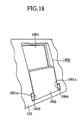
- FIG. 18 is a schematic diagram showing an overall arrangement of a display apparatus according to the first embodiment
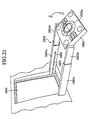
- FIGS. 19, 20 and 21 are schematic diagrams showing a state of the operation moved from the state in FIG. 18.
- reference numeral 1800 denotes a display apparatus provided in a central portion of an instrument panel 102.
- This display apparatus 1800 is constituted by: a displaying portion 1801 as a displaying means for displaying visual information; a supporting portion made up of a left side supporting portion 1803 and a right side supporting portion 1804, both serving as a supporting means for supporting an operating portion 1802 (to be described later) on both ends which correspond to lower peripheral portions 1801a of this displaying portion 1801 as viewed in FIG. 18; and the operating portion 1802 as an operating means for performing an operation of this display apparatus 1800.
- This operating portion 1802 is rotated on the supporting portion.
- the supporting portion constituted by the left side supporting portion 1803 and the right side supporting portion 1804 is formed by an arm portion.
- the arm portion At the time of setting to a first position in which the operating portion 1802 is housed, the arm portion is housed and, at the time of setting to a second position, the arm portion which moves coupled with the operating portion so as to separate the displaying portion 1801 and the operating portion 1802 projects forward.
- the left side supporting portion 1803 is constituted by a first left arm portion 1803a and a second left arm portion 1803b which is housed inside the first left arm portion 1803a, both 1803a/1803b being defined as the arm portion.
- the right side supporting portion 1804 is constituted by a first right arm portion 1804a and a second right arm portion 1804b which is housed inside the first right arm portion 1804a, both 1804a/1804b being defined as the arm portion.
- the first left arm portion 1803a and the first right arm portion 1804a are housed inside the instrument panel.
- the left side supporting portion 1803 and the right side supporting portion 1804 are, as shown in FIG. 18, housed inside the instrument panel.
- a slit-like groove portion 1805 is formed as shown in FIG. 21, and in a part of the right side surface of the first left arm portion 1803a, a groove portion 1805 is formed, which is similar to the groove portion 1805 formed in the first right arm portion 1804a.
- a projected portion 1806 is formed in a part of the left side surface of the second right arm portion 1804b. This projected portion 1806 is fit into the groove portion 1805 formed in the first right arm portion 1804a. It is thus so arranged that the projected portion 1806 slidably moves inside the groove portion 1805 coupled with the movement of the second right arm portion 1804b.
- a projected portion 1806 is formed in a part of the right side surface of the second left arm portion 1803b, which is similar to the projected portion 1806 formed in the second right arm portion 1804b. This projected portion 1806 is fit into the groove portion 1805 formed in the first left arm portion 1803a. It is thus so arranged that the projected portion 1806 slidably moves along the groove portion 1805 coupled with the movement of the second left arm portion 1803b.
- FIG. 22 is a sectional view showing a section in the longitudinal direction of the left side supporting portion 1803.
- FIGS. 23 and 24 show the state in which the first left arm portion 1803a and the second left arm portion 1803b project in the left direction as viewed in the figures, i.e., extend in the left direction, from the state shown in FIG. 22 to the state shown in FIG. 20.
- reference numeral 1810 denotes a roller portion provided inside the display apparatus. A contact surface of this roller portion 1810 comes into contact with the lower surfaces of the first left arm portion 1803a and the second arm portion 1803b.
- the roller portion 1810 rotates in the counterclockwise direction.
- the roller portion 1810 rotates in the counterclockwise direction.
- the roller portion 1810 rotates in the counterclockwise direction.
- the roller portion 1810 rotates in the counterclockwise direction.
- the roller portion 1810 rotates in the counterclockwise direction.
- the roller portion 1810 rotates in the counterclockwise direction.
- the state is as shown in FIG. 23, from the viewpoint of the relationship between the groove portion 1805 and the projected portion 1806, the projected portion 1806 formed on the right side of the second left arm portion 1803b slides, coupled with the movement of the second left arm portion 1803b, inside the groove portion 1805 formed in the right side surface of the first left side arm portion 1803a.
- the projected portion 1806 moves to the left end portion of the groove portion 1805, with the result that it gets in a state in which the projected portion 1806 is in contact with the left end portion of the groove portion 1805.
- the first left arm portion 1803a is moved, with the projected portion 1806 serving as a supporting point, from a state of contact with the left end portion of the groove portion 1805 in the direction S as shown in FIG. 19 to the state as shown in FIG. 24.
- the display apparatus as a whole will get into the state as shown in FIG. 20.
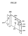
- FIG. 25 is a schematic diagram showing an principal portion of a rotary mechanism
- FIG. 26 is a schematic diagram showing a state of the operation of the rotary mechanism
- FIG. 27 is a schematic diagram showing an arrangement of an principal portion of the rotary mechanism.
- reference numeral 2500 denotes a rotation restricting plate portion for restricting the rotary motion of the operating portion 1802.
- This rotation restricting plate portion 2500 is constituted by: a fitting hole 2501 which supports, with fitting thereinto, a front end portion of a shaft portion 2701 which is integrally formed in a part of each end surface of the operating portion 1802 as shown in FIG. 27; a groove portion 2502 which is formed into an arcuate shape; and screw holes 2504 for mounting by screws or the like on a front end of this side of the right side surface of the second left arm portion 1803b and on a front end of this side of the left side surface of the second right arm portion 1804b.
- reference numeral 2700 denotes an element constituting a rotary shaft of the operating portion 1802 which is formed integrally with a part of each end surface of the operating portion 1802.
- This rotary shaft 2700 has also integrally formed with a plate portion 2702 which is formed into a disk shape and forms a projected portion 2503 in part thereof.
- the projected portion 2503 is fit into the fitting hole 2501 in the rotation restricting plate portion 2500, and a member 2710 to prevent the rotation restricting plate portion 2500 from being pulled out is mounted on the rotary shaft 2700 near a front end portion 2703 thereof.
- FIG. 25 shows a state in which the projected portion 2503 is fit into the groove portion 2502.
- Reference numeral 2503a denotes a position of the projected portion 2503 in which, as shown in FIGS. 18, 19 and 20, the operating portion 1802 is folded, i.e., is closed.
- Reference numeral 2503b shows a position of the projected portion 2503 in which, as shown in FIG. 21, the operating portion 1802 is opened. In this manner, it is so arranged that the rotary movement is restricted by the contact of the projected portion 2503 with the end portions of the groove portion 2502.
- A denotes a state in which the operating portion 1802 is closed.
- the projected portion 2503 in this state is in the position of 2503a.
- B shown in dotted lines denotes a position in which the operating portion 1802 is opened.
- the projected portion 2503 in this state is in the position of 2503b.
- the operating surface 1802a of the operating portion 1802 is set, as shown in FIG. 18, in a first position facing the display surface of the displaying portion 1801.
- the time of operation i.e., when an operation is made, after the operating portion 1802 is pulled out of the first position shown in FIG. 18, the operating portion 1802 rotates in the direction U as shown in FIG. 21, thereby setting the operating portion 1802 in a second position in which the operation of the operating surface 1802a of the operating portion 1802 is possible.
- the user pulls out the operating portion 1802 and, after having pulled out the operating portion 1802 to the predetermined position through the positions shown FIGS. 19 and 20, the operating portion 1802 rotates in the direction U as shown in FIG. 21, thereby appearing the operating surface 1802a in the vehicle compartment.
- the apparatus is constituted, together with the displaying portion and the operating portion, by the supporting means which supports the operating portion and which is retractable, and the rotary mechanism which rotates the operating portion.
- This enables an operation of the operating portion in a position favorite to the user.
- the operation can be made in a comfortable posture while the user remains seated, resulting in an improvement in the convenience.
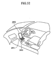
- FIG. 32 shows a state in which only the operating portion 2802 rotates to get into an operable state without pulling out the supporting portion. In this manner, depending on how the user uses, it may be performed only the rotary operation of the operating portion 2802 without projecting the supporting portion.
- the above first embodiment it lacks a description that display on the display surface in a state in which the operating surface 1802a of the operating portion 1802 is folded onto the displaying portion 1801 so that the display surface and the operating surface are overlapped with each other.
- the displaying is possible on a surface onto which the operating surface 1802a is not overlapped. Therefore, when the operating portion 1802 is set to the first position which is the housed position, it may be made a display only on the display surface not overlapped with the operating surface 1802.
- visual information such as map information or the like which is outputted by a navigation apparatus (not shown) or visual information which is outputted by an audio device, an image reproducing device or the like is displayed only on the display surface which is not overlapped with the operating portion 1802.
- the displaceable portion can be effectively utilized and the convenience of the user is improved.
- the display surface of the displaying portion 1801 which is not overlapped with the operating portion 1802 is displaceable.
- it may be changed the displaying scale based on the size of the displaceable display surface of the displaying portion 1801.
- the area of the display surface has a ratio of approximately 1:2 between a state in which the operating portion 1802 is housed and that in which it is not. Therefore, there has been a problem that despite an attempt to display the same displayed contents on the displaying portion 1801 under any circumstances, the visual information, if based on the same displaying scale, will be 1/2 in case the operating portion 1802 is housed as compared with the case in which it is not.
- the displaying scale is changed depending on the area of the display surface in order to display the same contents of visual information. For example, in case the size of the display surface of the displaying portion 1801 is 1:2, the scale ratio of the contents is changed to 1/2:1.
- the operating portion 1802 gets ready for operation.
- the operating portion 1802 may be housed, so that the displayed contents are changed into the small-scale. In this manner, the convenience of the apparatus can be further improved without missing the contents.
- the displaying portion 1801 shown in FIG. 18 enables a divided display in which a plurality of screens are displayed.
- the divided display is made when the displaying portion 1802 is set to the first position which is the housed position as shown in FIG. 18, the divided display may be made only on the display surface which is not overlapped with the operating surface 1802.
- the divided display may be made on the entire display surface of the displaying portion 1801.
- the operating portion 1802 when the operating portion 1802 is in the second position in which the operation thereof is possible, it may be arranged such that the operating surface 1802a of the operating portion 1802 forms an obtuse angle relative to the display surface of the displaying portion 1801. Having been arranged as described above, since the operating surface of the operating portion 1802 is set to a position easily accessible to the field of view of the user, the visibility of the operating surface and the operability are improved.
- the operating surface 1802a of the operating portion 1802 forms an obtuse angle relative to the display surface of the displaying portion 1801. It may be provided an angle adjusting means (not shown) for adjusting the angle formed between the operating surface of the operating portion 1802 and the display surface of the displaying portion 1801 in order to adjust an inclination of the operating portion 1802 to optimum to the user.
- setting of the operating portion 1802 according to his or her own body further improves the visibility and the operability.
- the operating portion 1802 when the operating portion 1802 is pulled out, the user himself pulls it out.
- a driving motor inside the display apparatus to constitute a driving mechanism for transmitting the driving force of this driving motor to the roller portion 1810 shown in FIG. 22.
- a switch may be provided in a part of the display apparatus so that the driving motor can be driven by the operation of this switch.
- the operating portion 1802 can be automatically pulled out or housed only by the operation of the switch. This eliminates this kind of troublesome operations, resulting in a further improvement in the convenience of the user.
- FIG. 1 is a schematic diagram showing a general arrangement of a device installation apparatus for a mobile body according to the eighth embodiment.
- FIG. 2 is a block diagram showing an overall arrangement of the device installation apparatus for a mobile body according to the eighth embodiment.
- FIG. 3 is a schematic diagram showing an arrangement of a principal portion in FIG. 1.
- reference numeral 100 denotes an automotive vehicle as a mobile body.
- a description is made based on a 6-passenger mini van type of automotive vehicle.
- Reference numeral 101 denotes a front glass
- reference numeral 102 denotes an instrument panel which is formed by resin or the like and disposed in a front of a vehicle compartment
- reference numeral 103 denotes a combination meter panel for disposing therein those meters such as a speedometer, a tachometer or the like which are provided on a side of the driver's seat (to be described later) in the instrument panel 102
- reference numeral 104 denotes a steering wheel.
- reference numeral 105 denotes a dash board which forms an upper portion of the instrument panel 102
- reference numeral 106 denotes a glove compartment which is provided on a side of an assistant driver's seat (to be described later) in the instrument panel 102
- reference numeral 2800 denotes a display apparatus which is provided in a central portion of the instrument panel 102.
- FIG. 28 is a schematic diagram showing an principal portion of a display apparatus
- FIG. 29 is a schematic diagram showing a state of the operation when an principal portion in FIG. 28 is operated
- FIG. 30 is a sectional view showing a section of the right side surface in FIG. 28
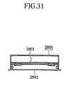
- FIG. 31 is a sectional view showing a section of a lower surface of an principal portion in FIG. 28.
- reference numeral 2800 denotes the display apparatus.
- This display apparatus 2800 is constituted by a displaying portion 2801 for displaying visual information, and an operating portion 2802 for performing the operation of the display apparatus 2800.
- a rotary shaft 2803 of the operating portion 2802 is provided in a part of the lower portion of the displaying portion 2801.
- the operating portion 2802 is rotatable in the direction P or Q on the rotary shaft 2803.
- the operating portion 2802 rotates in the direction P.
- the operating portion 2802 rotates in the direction Q.
- reference numeral 107 denotes front seats. These front seats are constituted by a driver's seat 107a and an assistant driver' s seat 107b.
- Reference numeral 108 denotes passengers' seats in an intermediate row. These intermediate seats 108 are constituted, like in the front seats 107, by a seat on the side of the driver's seat 107a, i.e., the right side seat 108a as viewed in FIG. 1 and a seat on the side of the assistant driver's seat 107b, i.e., the left side seat 108b as viewed in FIG. 1.
- rear seats not shown are provided behind the intermediate seats 108. Like in the front seats and the intermediate seats, they are also constituted by two seats.
- reference numeral 109 denotes a console box as an installing means which is provided in a position sandwiched between the driver's seat 107a and the assistant driver's seat 107b of the automotive vehicle 100 and in which a desired device 200 such as a compact disc (CD) player 201, a cassette tape player 202, a digital versatile disc (DVD) player 203 or the like can be installed.
- a desired device 200 such as a compact disc (CD) player 201, a cassette tape player 202, a digital versatile disc (DVD) player 203 or the like
- an engaging portion 109a for engaging with a rail portion 110 (to be described later) is provided, in. part of the center console box 109, a fixing lever (not shown) for fixing the center console box 109 is provided after having moved it to the predetermined position. This fixing lever is engaged with part of the rail portion 110 when the center console box 109 is fixed to the rail portion 110 and operated to release the engagement when the center console box 109 is moved.
- Reference numeral 110 is the rail portion as a guide means for movably guiding the center console box 109 in the longitudinal direction of the automotive vehicle 100, i.e., in the direction A or B in FIG. 1.
- This rail portion 110 is formed by cutting part of the floor of the automotive vehicle 100 into a slit. As shown in FIG. 3, it is so arranged that the engaging portion 109a of the center console box 109 slides inside the rail portion 110.
- the center console box 109 is guided along the rail portion 110.
- the center console box 109 desired devices 200 such as the CD player 201, the cassette tape player 202, the DVD player 203 or the like are disposed.
- An operating means 204 for operating these devices is further provided.
- a central control means 2011 for supervising the respective control of each device mounted on the automotive vehicle; a display control means 2021 for controlling the displaying means such as a display or the like; a volume control means 2031 for controlling a volume of a loud speaker 2032 which outputs sounds; an engine control means 2041 for controlling the operation of the engine 2042 mounted on the automotive vehicle 100; and an air conditioner control means 2051 for controlling the operation of an air conditioner 2052 mounted on the automotive vehicle 100.
- the display control means 2021, the volume control means 2031, the engine control means 2041 and the air conditioner control means 2051 are controlled in response to the operation commands of the central control means 2011.
- the central control means 2011 performs the predetermined operation controls, e.g., stopping the operation or the like.
- a command is outputted by the central control means 2011 to the display control means 2021 to take given control.
- the display control of the displaying means 2022 is take in response to the command of this central control means 2011, thereby displaying visual information on the displaying means 2022.
- FIGS. 4 and 5 respectively show the state in which the center console box 109 corresponds to the intermediate seats 108, and to the rear row (not shown).
- the center console box 109 is moved from the position shown in FIG. 1 in the direction B, it is moved through the position shown in FIG. 4 to the position shown in FIG. 5.
- the center console box 109 is moved in the direction A, it is moved in the reverse direction, i.e., from the position shown in FIG. 5 to the position shown in FIG. 1 through the position shown in FIG. 4.
- the center console box 109 as the installing means, which is provided in the position sandwiched between the driver's seat 107a and the assistant driver's seat 107b of the automotive vehicle 100 and in which the desired devices 200 as the CD player 201, the cassette tape player 202, the DVD player 203 or the like can be installed is movable along the rail portion 110. Therefore, it becomes possible for the passengers seated other than in the front seats to operate the audio device and the image reproducing device. Particularly, the replacement of memory media such as discs or the like to be inserted into the devices housed inside the center console box 109 by the passengers themselves improves the convenience of the apparatus.
- the movement of the center console box 109 housed therein the audio device and the image reproducing device to a position favorite to the passengers improves the convenience of the user.
- the CD player 201 the cassette tape player 202 and the DVD player 203 as examples of the devices to be housed inside the center console box.
- it may be provided a game playing device, a personal computer, or other devices quite foreign to the above devices such as a water boiling equipment or the like.
- the center console box which was described in the eighth embodiment may also be arranged as follows.
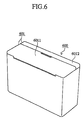
- FIG. 6 is a schematic diagram showing an arrangement of a principal portion of a device installation apparatus for a mobile body according to the ninth embodiment
- FIG. 7 is a schematic diagram showing the state in which a lid portion is opened from the state shown in FIG. 6, and
- FIG. 8 is a sectional side view showing a side section of FIG. 6.
- reference numeral 600 denotes a center console box as an installing means.
- a lid member 601 for the center console box 600 is provided on an upper portion of this center console box 600.
- This lid member 601 is constituted by a left-side lid member 6011 which is disposed on the left side as viewed in the figure and a right-side lid member 6012 which is disposed on the right side, both of which are independent of each other.
- One end portion of a side surface of the center console box 600 serves as an axis of rotation.
- the left-side lid member 6011 When the left-side lid member 6011 is to be opened as shown in FIG. 7, it rotates in the direction C and, when it is to be closed, it rotates in the direction D.
- the right-side lid member 6012 rotates in the direction F when it is opened and rotates in the direction E when closed.
- Reference numeral 701 shown in FIG. 7 denotes a mounting/dismounting release button which is operated by pushing in mounting or dismounting the devices housed inside the center console box 600.
- the operation of this mounting/dismounting release button 701 allows to mount and dismount the devices 702 into and out of the center console box. This enables free replacement of the devices housed inside the center console box.
- the mounting/dismounting release button 701 is operated in the state as shown in FIG. 7, the mounting or dismounting of the devices is released.
- reference numeral 801 shown in FIG. 8 denotes a connector as a mounting/dismounting means for detachably holding the audio device, the image reproducing device or the like to be housed inside the center console box 600 independent of one another.
- This connector 801 is provided in a plurality of pieces so that the detachably mounted audio device, the image reproducing device or the like can be provided therein.
- each of these connectors 801 there are provided pins for: an electric power supply line (not shown) which supplies electric power from a power buttery (not shown) mounted on the automotive vehicle; an audible information outputting line (not shown) which outputs audible information to be outputted from the audio device, the image reproducing device or the like to the central control means 2011 provided inside the instrument panel 102; and a visual information outputting line (not shown) which outputs the visual information.
- pins 8011 are arranged such that, when the audio device, the image reproducing device or the like is housed inside the center console box 600, the pins are fit into a connector (not shown) provided on a rear surface of the audio device, the image reproducing device or the like, thereby supplying electric power to the audio device, the image reproducing device or the like, and such that the audible information and the visual information to be outputted from the audio device and the image reproducing device are outputted to the central control means 2011.
- Reference numeral 8012 denotes a holding portion for holding the housed audible device and the image reproducing device by holding them when the audio device and the image reproducing device are housed into the center console box 600 and the connectors provided in the audio device and the image reproducing device are fit into the pins 8011.
- the audio device or the image reproducing device is to be dismounted from the connector 801 provided inside the center console box 600, the device to be dismounted from the center console box 600 is pulled up while operating the mounting/dismounting release button 701. Then, the holding portion 8012 is disengaged from the connector provided in the device with the help of this pulling-up force.
- the connector 801 inside the center console box 600 as described above, when the audio device or the image reproducing device is housed inside the center console box 600, the connectors provided in the audio device and the image reproducing device and the connectors 801 inside the center console box 600 are fit with each other to hold the audio device and the image reproducing device, and each of these devices can be dismounted from the connector 801. Therefore, the devices to be housed inside the center console box 600 can be freely replaced. In other words, even if a failure or the like is occurred in the devices, the devices can be easily removed because they are not fixed by means of screws or the like, so that maintainability of the apparatus is thus improved. Further, the easy operation of the apparatus improves the freedom in design of the apparatus as a system.
- a plurality of devices that can be housed inside the center console box 600 have been set forth. Alternatively, it may also be housed only one device therein. Arranging in this manner the same effect is obtained that the device to be housed inside the center console box 600 can easily be replaced.
- the electric power supply line, the audible information output line, the visual information output line or the like is used for connection between the audio device, the image reproducing device or the like housed in the center console box 109 and the central control means 2011 provided inside the instrument panel 102.
- a communication network may be established between them using the technology of "Bluetooth" which has recently been become the main current.
- Bluetooth is a wireless interface using as a carrier frequency an Industrial Scientific Medical (ISM) band of 2.4GHz requiring no licence, and it uses a spread spectrum technology of frequency hopping method.
- ISM Industrial Scientific Medical
- class 1 is +20dBm (maximum transmission distance is 100m)
- class 2 is +4dBm
- class 3 is 0dBm (maximum transmission distance is 10m).
- class 1 requires an externally mounted power amplifier circuit
- class 2 or class 3 will have to be considered.
- FIG. 9 is a block diagram showing an overall arrangement of the device installation apparatus for a mobile body according to the eleventh embodiment of this invention. It shows a center console box 900, an inside of an instrument panel 910, and an onboard local area network (LAN) 920 using the above “Bluetooth” technology.
- LAN local area network
- an operating means 9041 Inside the center console box 900, there are provided an operating means 9041, a CD player 9012, a cassette tape player 9022, and a DVD player 9032 which are operated by this operating means. Further, there are provided: a transmitting means 9042 for transmitting an operation command of the operating means 9041; a receiving means 9011 corresponding to the CD player 9012 for receiving the transmitted signal of this transmitting means 9042; a receiving means 9021 corresponding to the cassette tape player 9022; a receiving means 9031 corresponding to the DVD player 9032; a transmitting means 9013 for transmitting an output signal of the CD player 9012; a transmitting means 9023 for transmitting an output signal of the cassette tape player 9022; and a transmitting means 9033 for transmitting an output signal of the DVD player 9032.
- the transmitting means 9013, 9023, 9033 receives the signals transmitted from the transmitting means 9111 so that an operation command can be outputted to each device.
- the receiving means 9011 of the CD player 9012 receives an operation command in response to the operation command of the operating means 9041 through the transmitting means 9042.
- the CD player 9012 outputs audible and visual information.
- the signal outputted by this CD player 9012 is transmitted by the transmitting means 9013 and received by a transmitting/receiving means 9111 provided inside of the instrument panel 910.
- the receiving means 9021 or the receiving means 9031 receives the operation command through the transmitting means 9042.
- the cassette tape player 9022 or the DVD player 9032 outputs audible information or the visual information.
- This output signal is transmitted by the transmitting means 9023 or the transmitting means 9033 and received by the transmitting/receiving means 9111 of the central control means 9112 provided inside of the instrument panel 910.
- the central control means 9112 provided inside of the instrument panel 910 takes displaying control of the visual information through the transmitting/receiving means 9121 if the visual information is included in the signal received by the transmitting/receiving means 9111, thereby outputting the information to the displaying means 9123 for displaying on the displaying means 9123.
- the central control means 9112 takes control of volume of the audible information by the volume control means 9132 through the transmitting/receiving means 9111 if the audible information is included in the signal received by the transmitting/receiving means 9111, thereby outputting the information to a loud speaker 9133 for outputting a sound from the loud speaker 9133.
- an engine control means 9142 for controlling an engine 9143 mounted on the automotive vehicle.
- This engine control means 9142 is provided with a transmitting/receiving means 9141 for receiving the signal transmitted from the transmitting/receiving means 9111 in the central control means 9112.
- an air conditioner control means 9152 for controlling an air conditioner 9153 mounted on the automotive vehicle.
- This air conditioner control means 9152 is provided with a transmitting/receiving means 9151 for receiving a signal transmitted from the transmitting/receiving means 9111 in the central control means 9112.
- the above transmitting path is constituted as an onboard LAN 920.
- each of the audio devices and the image reproducing devices is provided with a transmitting/receiving means adopting the ISM band of 2.4GHz.
- the central control means 9112 provided inside the instrument panel 910 is also provided with the transmitting/receiving means 9111 using the ISM band of 2.4GHz to built a system using a wireless type of transmitting/receiving means.
- the audio device and the image reproducing device as well as wiring materials such as an electric power supply line, audible information output line or the like to take control of these devices, the wiring materials are no more required.
- the wiring space under the floor can be reduced, and the floor inside the center control box can be constructed in a clear way.
- each device can be centrally controlled and the freedom in design can be improved.
- the "Bluetooth" was used as the wireless technology.
- an IrDA type may also be used as an infrared-ray type of wireless technology.
- the wiring materials such as the electric power supply line, the visual information outputting line, the audible information outputting line or the like that were conventionally required to connect the devices are not required any more. As a consequence, an effect is obtained that the wiring space under the floor can be reduced.
- the arrangements in which the audio device or the image reproducing device housed in the center console box are opened to anybody. Alternatively, it may be opened only to the restricted user.
- FIG. 10 is a block diagram showing an overall arrangement according to the twelfth embodiment
- FIG. 11 is a flow chart showing the operation of FIG. 10.
- Reference numeral 1000 denotes a center console box. Inside this center console box 1000, a CD player 1001, a cassette tape player 1002 and a DVD player 1003 are provided. An operating means 1004 is provided for performing the predetermined operations of these devices.
- a user judging means 1010 for judging whether a user of the apparatus is an appropriate user or not is provided.
- This user judging means 1010 is arranged such that, only when the means 1010 has judged the user to be an appropriate user, the operation of the audio device and the image reproducing device housed in the center console box is permitted.
- the user judging means 1010 is provided with a finger print verifying means 1011 for judging whether the user is an appropriate user or not by verifying the user's fingerprint, and a voice verifying means 1013 for judging whether the user is an appropriate user or not by verifying the voices pronounced by the user.
- the fingerprint verifying means 1011 is provided with a fingerprint memory means 1012 for storing in advance the fingerprint information of the user to be compared with user's fingerprint when the fingerprint verification is done.
- the voice verifying means 1013 is provided with a voice memory means 1014 for storing in advance the voice information of the user to be compared with user's voice when the voice verification is done.
- a central control means 1021 for taking overall control of all the devices mounted on the automotive vehicle; a display control means 1022 for controlling the displaying means 1026 such as a display or the like; a volume control means 1023 for controlling the volume of the loud speaker 1027 which outputs a sound; an engine control means 1024 for controlling the operation of an engine 1028 mounted on the automotive vehicle; and an air conditioner control means 1025 for controlling the operation of an air conditioner 1029 mounted on the automotive vehicle.
- the display control means 1022, the volume control means 1023, the engine control means 1024 and the air conditioner control means 1025 are controlled by the operation command from the central control means 1021.
- the central control means 1021 performs the predetermined operation, e.g., stopping of operation or the like, to each device housed inside. the central console box 1000.
- step 100 when a user wishes to play the CD player 1002, the cassette tape player 1002 or the DVD player 1003 housed in the center console box 1000, the operator, i.e., the user pushes his or her finger against the fingerprint verifying means 1011 so as to detect his or her fingerprint.
- the fingerprint verifying means 1011 reads out from the fingerprint memory means 1012 the fingerprint that has been stored in advance by the approved user and makes a comparison with the fingerprint detected at step 101. If the two fingerprints have judged to coincide with each other as a result of comparison (step 102), the user can gain access to each of the devices housed in the center console box 1000.
- each of the devices is operated based on this operation (step 104).
- step 104 After having executed this step 104, if the ignition switch is turned off, the operation of each of the devices housed in the center console box 1000 is prohibited. Unless a fingerprint verification is done once again, and judged the intended user to be the appropriate user, the devices are set to inoperable state (step 105).
- step 105 After having been executed this step 105, when the ignition switch is turned on, the procedure returns to step 101 to get into a wait condition to make a judgement as to whether the fingerprint verifying means 1011 has detected a fingerprint or not (step 106). The processing is repeated after step 102.
- step 101 when a fingerprint has not detected at step 101, it will again get into a wait condition for the fingerprint detection, and the procedure returns to step 101.
- step 102 the fingerprint verifying means 1011 has judged that the detected fingerprint does not coincide with the fingerprint that has been stored in the fingerprint storing means 1012, the procedure proceeds to step 105 if no operation is made at step 103 to the device housed in the center console box 1000 even after the predetermined time elapsed. It will be get into a wait condition for the ignition switch to be turned off.
- step 105 the procedure returns to step 103 and will get into a wait condition for the operation of the devices.
- step 106 the procedure returns again to step 106. It will get into a wait condition for the ignition switch to be turned on.
- the restriction on the user can be imposed.
- the imposition of such restriction on the user leads to the prevention of operating means from being tampered by children, or to the protection of the devices from being stolen, resulting in an improvement in the convenience of the apparatus.
- the restriction of the user is imposed on the audio device or the image reproducing device housed in the center console box, by using the user judging means, a restriction of the user is imposed on the audio device or the image reproducing device housed in the center console box.
- each device may also be imposed the restriction, aside from the restriction on the operation of each device, and on the mounting and dismounting of each device.
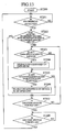
- FIG. 12 is a block diagram showing an overall arrangement according to the thirteenth embodiment, and FIG. 13 is a flow chart showing the operation of FIG. 12.
- Reference numeral 1005 denotes a mounting/dismounting operation control means for imposing a restriction as to whether the mounting or dismounting operation of the CD player 1001, the cassette tape player 1002 and the DVD player 1003 housed in the center console box 1000 will be allowed or not based on the result of judgement by the user judging means 1010.
- step 200 when a user wishes to play the CD player 1002, the cassette tape player 1002 or the DVD player 1003 housed in the center console box 1000, the operator, i.e., the user pushes his or her finger against the fingerprint verifying means 1011 so as to detect his or her fingerprint.
- the fingerprint comparing means 1011 reads out from the fingerprint memory means 1012 the fingerprint that has been stored in advance by the approved user and makes a comparison with the fingerprint detected at step 201. If the two fingerprints have judged to coincide with each other as a result of comparison (step 202), the user can gain access to each of the devices housed in the center console box 1000.
- each of the devices is operated based on this operation (step 204).
- the mounting/dismounting control means 1005 makes it possible, based on this operation, to dismount the device to be mounted on or dismounted from the center console box 1000 (step 206).
- each of the devices housed in the center console box 1000 gets into a prohibited state, and the mounting/dismounting operation of each device is also set to this state. Unless a fingerprint verification is done once again, and judged the intended user to be an appropriate user, each device is set to an inoperable state and unmounting/undismounting state (step 207).
- step 207 After having executed this step 207, if the ignition switch is turned on, the procedure returns to step 201 to make a judgement as to whether the fingerprint control means 1011 has detected a fingerprint or not (step 208). The same processing is repeated after step 202.
- step 201 if a fingerprint has not detected at step 201, it will again get into a wait condition for the fingerprint detection, and the procedure returns to step 201.
- step 202 the fingerprint verifying means 1011 has judged that the detected fingerprint does not coincide with the fingerprint that has been stored in the fingerprint storing means 1012, the procedure proceeds to step 207 if no operation is made at step 205 to the device housed in the center console box 1000 even after the predetermined time elapsed. The state will thus get into a wait condition for the ignition switch to be turned off.
- step 205 the procedure proceeds to step 205, and the state will get into a wait condition for the mounting/dismounting operation of each device.
- step 207 if the ignition switch is not turned off at step 207, the procedure returns to step 203 and the state will get into a wait condition for the operation of the device.
- step 208 the procedure returns again to step 208. The state will thus get into a wait condition for the ignition switch to be turned on.
- the restriction on the user can be imposed to prevent the devices housed in the central console box 1000 from being operated, and also to prevent each of the devices housed in the center console box from being dismounted.
- the restriction of dismounting of the devices ensures the further prevention of the tampering and the theft.
- a method is employed for disabling the mounting or dismounting operation by canceling the above operation even if the mounting/dismounting release button 701 shown in FIG. 7 is operated.
- the fingerprint verifying means and the voice verifying means are provided. Alternatively, only one of them may be provided. In addition, both may be provided so that an appropriate user can be judged by using the results of judgement of both.
- the above Arrangements contribute to restriction of the user, and to further improvement in the accuracy of the apparatus.
- audio devices and image reproducing devices are disposed in the center console box. It may also be provided a displaying means for displaying visual information.
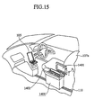
- FIG. 14 is a schematic diagram showing an arrangement of a principal portion according to the fifteenth embodiment
- FIGS. 15 and 16 are schematic diagrams of a principal portion showing the states of the displaying means moved from the state in FIG. 14.
- reference numeral 105 denotes a displaying means such as a display or the like.
- This displaying means 105 is constituted by an operating portion 1051 and a displaying portion 1052.
- This operating portion 1051 is rotatable in the direction H or G in FIG. 14. When the operating portion is folded, it rotates in the direction H so that the operating surface of the operating portion 1051 faces the displaying portion 1052.
- Reference numeral 107a denotes a driver's seat and reference numeral 1400 denotes a center console box.
- this center console box 1400 a displaying means 1401 is provided, and the display surface of this displaying means 1401 faces backward.
- Reference numeral 1402 denotes a housing space formed in the center console box 1401 for housing therein the displaying means 1401. It is so arranged that the displaying means 1401 can be wholly housed inside the center console box 1400.
- the displaying means 1401 When the displaying means 1401 is in use, it is disposed as shown in FIG. 14. When this displaying means 1401 is to be housed inside the center console box 1400, the orientation of the displaying means 1401 is changed to the direction I as shown in FIG. 15.
- the displaying means 1401 is laid down in the direction K to house it inside the center console box 1400.
- the center console box 1400 is thus provided, aside from the audio device and the image reproducing device, with the displaying means 1401 for displaying the visual information of these devices.
- this displaying means 1401 is housed inside the center console box 1400.
- the displaying means is provided in the center portion or the like in the instrument panel, the passengers seated in a position behind the front seats are difficult to see the visual information. This arrangement, however, has an effect that these passengers are easy to see the visual information, resulting in an improvement in the visibility of the visual information.
- center console box and the rail portion are provided on the floor portion inside the automotive vehicle.
- the center console box and the rail portion may also be provided on a roof portion of the automotive vehicle.
- FIG. 17 is a schematic diagram showing a general arrangement according to the sixteenth embodiment.
- Reference numeral 107a denotes a driver's seat
- reference numeral 108a denotes a right-side intermediate seat positioned just behind the driver's seat
- reference numeral 108b denotes a left-side intermediate seat positioned just behind the assistant driver's seat.
- Reference numeral 1700 denotes a roof portion inside the automotive vehicle.
- a device installation apparatus for a mobile body is constituted, which is made up of: a center console box 1710 housed therein a plurality of audio devices and image reproducing devices; and a rail portion 1720 which is internally engaged with an engaging portion (not shown) formed in part of the center console box and provided in the roof portion positioned between the seats disposed on the right side and the seats disposed on the left side so as to extend in the longitudinal direction of the automotive vehicle.
- This center console box 1710 is movable, like in the above first embodiment, in the direction M or N shown in FIG. 17.
- the center console box 1710 and the rail portion 1720 are provided in the roof portion inside the automotive vehicle, it is possible to offer a situation in which the above apparatus can be utilized in a mobile body such as a bus, an electric train, an airplane or the like in which the floor portion such as in the automotive vehicle cannot be used as a passage for the passengers. As a result, an effect is obtained that more wider applications can be found, and that the limited space inside the mobile body can be effectively used.
- the above sixteenth embodiment has bee set forth with put a limitation that the floor portion of the automotive vehicle cannot be used. Needless to say, this apparatus may also be used in a case in which the floor portion can be used.
- the rail portion in both the floor portion and the roof portion so that, depending on the purpose of use, the center console box can be placed to either of the rail portions.
- the center console box when the center console box is moved, it is manually moved by the user.
- a roller portion may also be provided, which comes into contact with the engaging portion of the center console box so as to rotate by a driving force of a driving motor.
- the center console box which is in contact with the roller portion is automatically moved, by rotating the roller portion, along the guide of the rail portion.
- the driving motor is rotated by receiving the operation command.
- the roller portion which rotates in response to this rotation, the center console box is automatically moved.
- the center console box can be automatically moved by the operation of the user. Alternatively, it maybe automatically returned to the predetermined position, i.e., to a default position when the ignition switch is turned on.
- the predetermined position is a position which is convenient to the user
- the position of the center console box which is changed by the movement of the center console box is reset when the ignition switch is turned off to automatically move it to the default position. Therefore, the user is not obliged to move the center console box whenever he or she is on board the automotive vehicle, resulting in an improvement in the convenience of the user.
- the center console box is returned to the predetermined position, i.e., to a default position.
- the default position may be set to a position near the seat of the driver who is the most frequent passenger of the automotive vehicle, i.e., to a position between the driver's seat and the assistant driver's seat.
- the rail portion may be provided with a plurality of recessed portions at an interval, e.g., of 5cm as engaging portions for engaging the center console box.
- the center console box 109 When the center console box 109 is moved based on the guide of the rail portion 110, the center console box 109 may be engaged with any one of the plurality of recessed portions. It is thus so arranged that the center console box is engaged with the recessed portion and the movement of the center console box is once stopped there.
- the recessed portions formed in a part of the rail portion may be provided so as to correspond to the positions of seats disposed inside the automotive vehicle.
- the operability of the moving operation of the center console box can further be improved.
- the display apparatus is suitable for use as that display apparatus for a mobile body which enables an operation of the operating means from a position remote from the displaying means for displaying thereon visual information.
Abstract
Description
- This invention relates to a display apparatus, particularly to a display apparatus for a mobile body, which is mounted on an automotive vehicle or the like, and is provided with a displaying means and an operating means for performing an operation of the displaying means, when the operation of the operating means is performed, the operating means can be projected such that it separates from the displaying means.
- FIG. 33 is a schematic diagram showing a principal portion of an inside of a conventional automotive vehicle.
- As shown in FIG. 33, in the conventional automotive vehicle,
reference numeral 330 denotes an instrument panel provided in a front portion inside the automotive vehicle,reference numeral 331 denotes an audio system such as a radio receiver, a cassette deck player, a compact disc (CD) player or the like provided in a central portion 330a of theinstrument panel 330,reference numeral 332 denotes a dash board provided in a central upper portion of theinstrument panel 330, reference numeral 333 denotes a steering wheel provided on the right of theinstrument panel 330,reference numeral 340 denotes a driver's seat,reference numeral 341 denotes an assistant driver's seat, andreference numeral 350 denotes a central console box disposed in a position sandwiched between the driver'sseat 340 and the assistant driver'sseat 341. - Conventionally, it has been the dominant influence of the times to configure such that the
audio system 331 is disposed in the central portion 330a of theinstrument panel 330. - On the other hand, with the recent wide spreading of a navigation system, there have gradually been come into market of the automobile vehicle of the following arrangements, i.e., an arrangement in which a main body (not shown) of the navigation system is disposed under the front seat such as the driver's seat, the assistant driver's seat or the like so that a displaying portion for displaying thereon map information to be outputted from the navigation system is disposed near the central portion of the instrument panel; an arrangement in which the space for disposing an audio system is narrowed to dispose the displaying portion in an upper central portion of the instrument panel, i.e., to embed it inside the dash board; and an arrangement in which instruments indicating the state of a brake system which is disposed on the driver's seat side of the instrument panel, are disposed in the central portion of the instrument panel. This kind of arrangements will come to be the main current in the future.
- In addition, arrangements considered disposition of the displaying portion, there have been known automobile vehicles of the following arrangements: i.e., an arrangement in which the displaying portion is disposed in the central upper portion of the instrument panel, i.e., is embedded inside the dash board; and an arrangement in which the displaying portion is embedded previously inside a part of a group of audio devices disposed in the central portion of the instrument panel, after the displaying portion is projected forward when it is in use, a display surface of the displaying portion moves substantially in parallel with the surface in the central portion of the instrument panel (in-dash type display apparatus).
- In this background, Japanese Patent Application Laid-open No. 297391/1998 discloses an arrangement in which switches for the audio devices, the air conditioner or the like which are conventionally disposed in the central portion of the instrument panel are provided inside a center console disposed between the driver's seat and the assistant driver's seat. FIG. 34 is a schematic diagram of a principal portion of the above arrangement.
- In FIG. 34,
reference numeral 1 denotes an instrument panel provided in a front portion inside the automobile vehicle,reference numeral 2 denotes a steering wheel provided on the right side of theinstrument panel 1,reference numeral 3 denotes a gear shift lever provided in the central lower portion of theinstrument panel 1,reference numeral 4 denotes a display provided in a central upper portion of theinstrument panel 1, andreference numeral 5 denotes front seats, thefront seats 5 being disposed by arranging an assistant driver'sseat 5a and a driver'sseat 5b in a line. - In addition, in a position sandwiched between the assistant driver's
seat 5a and the driver'sseat 5b, acenter console 6 is provided. As shown in FIG. 35, thecenter console 6 is provided with alid 6a and a housing portion is formed inside thecenter console 6 which is opened and closed by thislid 6a. - Further, in a part of the front of the
center console 6, aswitch disposing portion 6b which is formed in a recessed shape is provided. It is thus so arranged that aremote control unit 7 can be detachably mounted in thisswitch disposing portion 6b. - Having been arranged as described above, it allows a passenger seated in the driver's seat or in the assistant driver's seat of the automotive vehicle to be easily operated the switches in a seated posture.
- Further, Japanese Patent Application Laid-open No. 185547/1992 discloses a construction of a conventional improved model of an in-dash type of display apparatus. FIG. 36 is an overall arrangement view of this apparatus.
- In addition, FIGS. 37 and 38 are figures explaining states of the operation this display apparatus. FIG. 37 shows a state in which the display is not in use and FIG. 38 shows a state in which the display is moving to the predetermined position so as to get into the state in FIG. 36 in which the display is in a position ready for use.
- In FIGS. 36, 37 and 38,
reference numeral 10 denotes a casing,reference numeral 11 denotes the display which is housed inside thecasing 10 when it is not in use and which is taken out of thecasing 10 when it is in use, andreference numeral 12 denotes a sliding member (arm) for supporting thedisplay 11. This slidingmember 12 is, when thedisplay 11 is being housed, housed inside thecasing 10 together with thedisplay 11. - However the conventional audio devices and the image reproducing devices are arranged as described above and are mounted inside the automotive vehicle. There has been a problem that the space for disposition is limited in the central portion of the instrument panel, and that the devices to be installed in this space must therefore be deliberately selected by the user. Particularly, the user who wishes to equip various kinds of audio deices and image reproducing devices inside the automotive vehicle suffers from a serious inconvenience.
- Further, the audio device is disposed in the central portion of the instrument panel. Therefore, there has been a problem that the replacement of the recording media such as cassette tapes, digital audio tapes (DAT's), compact discs (CD's), minidiscs (MD's), digital versatile discs (DVD's) or the like, or the simultaneous sitting operation of each device or that or a plurality of devices are only allowed for passengers seated in the front driver's seat and the assistant driver's seat. Therefore, there has abeen a problem that passengers other than those seated in the front seats, i.e., the passengers seated in the rear seats are not allowed to perform the above works in a seated state, with the result that the passengers seated in the rear seats suffer from a serious inconvenience.
- In addition, passengers are seated far from the displaying means. Therefore, there has been a problem that the disposition of the displaying means for displaying visual information from the image reproducing device or the like is disposed in the central portion of the instrument panel provides the passengers seated in the front seats a better visibility. However, it provides the passengers seated in the rear seats a poor visibility.
- Further, when the audio device or the image reproducing device is operated, the operating means thereof is normally constituted integrally with the device. Therefore, there has been a problem that the operator is obliged to extend his or her arm toward the central portion of the instrument panel. It follows that the passengers seated in the rear seats cannot operate it, and even the passengers seated in the front seats must also change their posture from a posture leaning back in the seat to a posture forwardly bent in the seat before operating the device. Accordingly, the operation cannot easily be made.
- An arrangement in which an operating means is separated as a remote controller (hereinafter refers as a remocon) from the apparatus itself is also known. In this kind of arrangement, after having operated with the remote controller, the remote controller is often left detached from the housing place. ordinarily, the remote controller is small in size. Therefore, there has been a problem that it is apt to lose, and thus the operator gets into the trouble that he or she has to look for it before operating.
- Further, the audio device, the image reproducing device or the like is disposed in the central portion of the instrument panel and fixed such that the connection of wires or the like is made inside the instrument panel, the number of devices disposable in the instrument panel having only a narrow space available is limited. Therefore, in disposing, a user is compelled to deliberately select the specific devices. In addition, there is a problem that, since the devices are fixed to part of the instrument panel by means of screws or the like, the replacing work of the device now mounted to a different device is cumbersome.
- Further, when devices disposed in the apparatus are activated, anybody can operate them. Therefore, when children are present in the passengers, there is a problem that persons who are not welcome to operate the devices can also gain an easy access to their operation.
- Further, when the devices disposed in the apparatus are detachable, anybody can detach them. Therefore, there is a problem that the devices mounted on the apparatus are subject to the damages of stealing, tampering or the like.
- Further, the operating means such as a touch panel or the like for operating the displayed contents of the displaying means is disposed together with the displaying means in the central portion of the instrument panel. Therefore, there is a problem that, when the operating means is operated, the operator must change his or her posture from one leaning back to the seat to one forwardly bent in the seat before operating the operating means, or the operator is obliged to extend his or her arm to the operating means, with the result that the operation cannot easily be done.
- Further, in case the space between the seats is devoted to a passage for the passengers like in a bus or the like, among the mobile bodies, there has been a problem that nothing can be disposed on the floor because of a possible hindrance to the passage of the passengers.
- This invention has been made to solve the above described problems. An object of the invention is to provide a display apparatus for improving an operation of the displayed contents or the like of the displaying means in a posture leaning back in a seat, i.e., in a relaxedly seated posture, by providing a displaying means disposed in the central portion of the instrument panel with an operating means which projects rearward of the automotive vehicle compartment.
- Another object of the invention is to provide a display apparatus for preventing the operating means from being lost, by arranging the displaying means and the operating means separable through a supporting means.
- Another object of the invention is to provide a display apparatus for recognizing visual information, irrespective of a state of the operation of the operating device, by making a display only by the display surface displayable even when the operating means is overlapped with the displaying means.
- Another object of the invention is to provide a display apparatus for recognizing all of the visual information to be displayed, irrespective of the size of the area of the display surface, by changing the ratio of scale of displayed contents depending on the area of the display surface as a result of overlapping of the operating means with the displaying means, so as to further improve the convenience of the apparatus.
- Another object of the invention is to provide a display apparatus for recognizing the contents of the divided display, irrespective of the size of the area of the display surface, by arranging that, even if the area of the display surface of the displaying means is varied due to the overlapping of the operating means with the displaying means, the divided display can be made depending on each case, so as to improve the convenience of the apparatus.
- Another object of the invention is to provide a display apparatus for adapting an operation to respective users, by setting the angle of the operating means relative to the displaying means depending on the preference of the user, so as to further improve the operability of the apparatus.
- Another object of the invention is to provide a display apparatus for a mobile body which is disposed inside the mobile body together with the display apparatus, by providing an audio device and an image reproducing device on an installing means which is disposed in a position sandwiched between a front driver's seat and an assistant driver's seat, and movable in the longitudinal direction of the mobile body, for enabling not only for the passengers seated in the front seats but also for the passengers seated in the rear seats to directly operate the devices installed inside the installing means, so as to improve the convenience of the passengers and the operability.
- Another object of the invention is to provide a display apparatus for a mobile body which is disposed inside the mobile body together with the display apparatus, by arranging the installing means movably to a position which is suitable for each of the front seats, rear seats and the intermediate seats between the front seats and the rear seats, for enabling the passengers seated in all of the seats inside the mobile body to operate the devices, so as to improve the convenience of the passengers.
- Another object of the invention is to provide a display apparatus for a mobile body which is disposed inside the mobile body together with the display apparatus, by moving the installing means to a position which is suitable for the front seats, the rear seats, and the intermediate seats between the front seats and the rear seats, for enabling the passengers seated in all of the seats to replace the memory medium inserted into each of the devices, so as to improve the convenience of the passengers.
- Another object of the invention is to provide a display apparatus for a mobile body which is disposed inside the mobile body together with the display apparatus, by proving the installing means with a mounting/dismounting means for detachably holding the devices, so as to easily and freely replace the devices installed inside the installing means.
- Another object of the invention is to provide a display apparatus for a mobile body which is disposed inside the mobile body together with the display apparatus, by disposing a guide means for guiding the installing means not only on the floor portion but also on the roof portion, and by disposing the installing means on the roof portion even in case the installing means cannot be disposed on the floor portion, so as to find more wiser applications of the apparatus and to further improve the convenience of the apparatus.
- Another object of the invention is to provide a display apparatus for a mobile body which is disposed inside the mobile body together with the display apparatus, by restricting the user of the devices disposed in the installing means, so as to prevent the apparatus from being wrongly operated or tampered.
- Another object of the invention is to provide a display apparatus for a mobile body which is disposed inside the mobile body together with the display apparatus, by restricting mounting or dismounting of the devices installed in the installing means, so as to prevent the apparatus from being wrongly operated, or to prevent the devices installed inside the installing means from being stolen.
- Another object of the invention is to provide a display apparatus for a mobile body which is disposed inside the mobile body together with the display apparatus, by providing the installing means with a displaying means that can be housed inside the installing means, so as to improve the visibility of the visual information even by the passengers seated in the rear seats, and to further improve the convenience of the apparatus.
- The display apparatus according to this invention comprises: a displaying means for displaying visual information; an operating means for outputting the predetermined signal based on an operation; a supporting means for supporting the displaying means, the supporting means being provided near a peripheral portion of the displaying means, the operating means being rotated on the supporting means. Thus, depending on how the operating means is used, the rotation of the operating means toward the displaying means improves the operability of the operating means.
- The display apparatus according to this invention is arranged such that the operating means is set, at a time of non-operation, to a first position in which an operating surface faces a display surface of the displaying means and is set, at a time of operation, to a second position in which, rotating from the first position, an access to the operating surface is allowed. Therefore, at the time of non-operation, this prevents the operating means from being wrongly operated, resulting in an improvement in the convenience of the apparatus.
- The display apparatus according to this invention is arranged such that the supporting means comprises an arm portion, the arm portion being housed when the operating means is set to the first position and being projected forward when the operating means is set to the second position, so as to separate the displaying means from the operating means. Thus, when the operating means is operated, this enables operation thereof from a position far from the displaying means. Widening the operable range further improves the operability of the apparatus.
- The display apparatus according to this invention is arranged such that, when the operating means is set to the first position, the displaying means makes display only on a display surface which is free from overlapping with the operating means. Thus, even in case the area of the displaying means is small, displaying can be made only within this display surface, resulting in an improvement in the convenience of the apparatus.
- The display apparatus according to this invention changes a displaying scale depending on a size of the display surface available for displaying thereon. Thus, irrespective of the size of the area of the display surface, the contents can be displayed without missing the contents. The visual information to be displayed can thus be recognized, resulting in a further improvement in the convenience of the apparatus.
- The display apparatus according to this invention is arranged such that the displaying means enables a divided display in which a plurality of screens are displayed, in case the divided display is made when the operating means is set to the first position, the divided display is made only on the display surface free from overlapping with the operating means, and that, in case the divided display is made when the operating means is set to the second position, the divided display is made on all of the display surface. Thus, irrespective of the size of the area of the display surface, this makes it possible the divided display, resulting in an improvement in the convenience of the apparatus.
- The display apparatus according to this invention is arranged such that the second position is a position in which the operating surface of the operating means forms an obtuse angle relative to the display surface of the displaying means. Thus, this facilitates the operation by the user and improves the operability of the apparatus.
- The display apparatus according to this invention further comprises an angle adjusting means for adjusting an angle to be formed between the operating surface of the operating means and the display surface of the displaying means. Thus, setting of the operating means to an angle favorite to the user facilitates the operation by the user, and further improves the operability of the apparatus.
-
- FIG. 1 is a schematic diagram showing a general arrangement of a device installation apparatus for a mobile body to be mounted on an automotive vehicle together with the apparatus according to the eighth embodiment of this invention.
- FIG. 2 is a block diagram showing an overall arrangement of the device installation apparatus for a mobile body to be mounted on an automotive vehicle together with the display apparatus according to the eighth embodiment of this invention.
- FIG. 3 is a schematic diagram showing an arrangement of a principal portion in FIG. 1.
- FIG. 4 is a schematic diagram showing a state of the operation of a principal portion.
- FIG. 5 is a schematic diagram showing a state of the operation of a principal portion.
- FIG. 6 is a schematic diagram showing an arrangement of a principal portion of a device installation apparatus for a mobile body to be mounted on an automotive vehicle together with the display apparatus according to the ninth embodiment of this invention.
- FIG. 7 is a schematic diagram showing the state in which a lid portion is opened moved from the state in FIG. 6.
- FIG. 8 is a sectional side view showing a side section of FIG. 6.
- FIG. 9 is a block diagram showing an overall arrangement of the device installation apparatus for a mobile body to be mounted on an automotive vehicle together with the display apparatus according to the eleventh embodiment of this invention.
- FIG. 10 is a block diagram showing an overall arrangement of a device installation apparatus for a mobile body to be mounted on an automotive vehicle together with the display apparatus according to the twelfth embodiment of this invention.
- FIG. 11 is a flow chart showing the operation of FIG. 10.
- FIG. 12 is a block diagram showing an overall arrangement of a device installation apparatus for a mobile body to be mounted on an automotive vehicle together with the display apparatus according to the thirteenth embodiment of this invention.
- FIG. 13 is a flow chart showing the operation of FIG. 12.
- FIG. 14 is a schematic diagram showing an arrangement of a principal portion of a device installation apparatus for a mobile body to be mounted on an automotive vehicle together with the display apparatus according to the fifteenth embodiment of this invention.
- FIG. 15 is a schematic diagram of a principal portion showing a state of moving the displaying means moved from the state in FIG. 14.
- FIG. 16 is a schematic diagram of a principal portion showing a state of moving the displaying means moved from the state in FIG. 14
- FIG. 17 is a schematic diagram showing a general arrangement of a device installation apparatus for a mobile body to be mounted on an automotive vehicle together with the display apparatus according to the sixteenth embodiment of this invention.
- FIG. 18 is a schematic diagram showing an overall arrangement of a display apparatus according to the first embodiment.
- FIG. 19 is a schematic diagram showing a state of the operation moved from the state in FIG. 18.
- FIG. 20 is a schematic diagram showing a state of the operation moved from the state in FIG. 18.
- FIG. 21 is a schematic diagram showing a state of the operation moved from the state in FIG. 18.
- FIG. 22 is a sectional view showing a section of a principal portion of the display apparatus according to the first embodiment.
- FIG. 23 is a schematic diagram showing a state of the operation of a principal portion.
- FIG. 24 is a schematic diagram showing a state of the operation of a principal portion.
- FIG. 25 is a schematic diagram showing a principal portion of a rotary mechanism.
- FIG. 26 is a schematic diagram showing a state of the operation of the rotary mechanism.
- FIG. 27 is a schematic diagram showing an arrangement of a principal portion of the rotary mechanism.
- FIG. 28 is a schematic diagram showing a principal portion of a display apparatus according to the eighth embodiment.
- FIG. 29 is a schematic diagram showing a state of the operation when a principal portion in FIG. 28 is operated.
- FIG. 30 is a sectional view showing a section of the right side surface in FIG. 28.
- FIG. 31 is a sectional view showing a section of a lower surface of a principal portion in FIG. 28.
- FIG. 32 is a schematic diagram showing an operation of a principal portion of the display apparatus according to the first embodiment.
- FIG. 33 is a detail view showing a principal portion of an inside of a conventional mobile body.
- FIG. 34 is a detailed view of a principal portion of an inside of a conventional mobile body.
- FIG. 35 is a schematic diagram showing an arrangement of a center console box provided inside a conventional mobile body.
- FIG. 36 is a schematic diagram showing an arrangement of a prncipal portion of a display apparatus provided inside a conventional mobile body.
- FIG. 37 is a schematic diagram showing a state of operation of the display apparatus provided inside the conventional mobile body.
- FIG. 38 is a schematic diagram showing a state of operation of the display apparatus provided inside the conventional mobile body.
-
- In order to describe this invention in more detail, best mode for carrying out this invention will now be described with reference to the accompanying drawings.
- A description will be made about a display apparatus according to the first embodiment of this invention.
- FIG. 18 is a schematic diagram showing an overall arrangement of a display apparatus according to the first embodiment, FIGS. 19, 20 and 21 are schematic diagrams showing a state of the operation moved from the state in FIG. 18.
- In FIG. 18,
reference numeral 1800 denotes a display apparatus provided in a central portion of aninstrument panel 102. Thisdisplay apparatus 1800 is constituted by: a displayingportion 1801 as a displaying means for displaying visual information; a supporting portion made up of a leftside supporting portion 1803 and a rightside supporting portion 1804, both serving as a supporting means for supporting an operating portion 1802 (to be described later) on both ends which correspond to lowerperipheral portions 1801a of this displayingportion 1801 as viewed in FIG. 18; and theoperating portion 1802 as an operating means for performing an operation of thisdisplay apparatus 1800. Thisoperating portion 1802 is rotated on the supporting portion. - In addition, in FIGS. 19 and 20, the supporting portion constituted by the left
side supporting portion 1803 and the rightside supporting portion 1804 is formed by an arm portion. At the time of setting to a first position in which theoperating portion 1802 is housed, the arm portion is housed and, at the time of setting to a second position, the arm portion which moves coupled with the operating portion so as to separate the displayingportion 1801 and theoperating portion 1802 projects forward. The leftside supporting portion 1803 is constituted by a firstleft arm portion 1803a and a secondleft arm portion 1803b which is housed inside the firstleft arm portion 1803a, both 1803a/1803b being defined as the arm portion. In addition, the rightside supporting portion 1804 is constituted by a firstright arm portion 1804a and a secondright arm portion 1804b which is housed inside the firstright arm portion 1804a, both 1804a/1804b being defined as the arm portion. The firstleft arm portion 1803a and the firstright arm portion 1804a are housed inside the instrument panel. In other words, in case theoperating portion 1802 is not in use, the leftside supporting portion 1803 and the rightside supporting portion 1804 are, as shown in FIG. 18, housed inside the instrument panel. - In a part of each of those surfaces of the first
left arm portion 1803a and the firstright arm portion 1804a which face each other, i.e., in a part of the left side surface of the firstright arm portion 1804a, a slit-like groove portion 1805 is formed as shown in FIG. 21, and in a part of the right side surface of the firstleft arm portion 1803a, agroove portion 1805 is formed, which is similar to thegroove portion 1805 formed in the firstright arm portion 1804a. - Further, in a part of the left side surface of the second
right arm portion 1804b, a projectedportion 1806 is formed. This projectedportion 1806 is fit into thegroove portion 1805 formed in the firstright arm portion 1804a. It is thus so arranged that the projectedportion 1806 slidably moves inside thegroove portion 1805 coupled with the movement of the secondright arm portion 1804b. In addition, in a part of the right side surface of the secondleft arm portion 1803b, a projectedportion 1806 is formed, which is similar to the projectedportion 1806 formed in the secondright arm portion 1804b. This projectedportion 1806 is fit into thegroove portion 1805 formed in the firstleft arm portion 1803a. It is thus so arranged that the projectedportion 1806 slidably moves along thegroove portion 1805 coupled with the movement of the secondleft arm portion 1803b. - Next, with reference to FIGS. 22 through 24, the mechanism for performing the operation of projecting the
operating portion 1802 toward this side from the displayingportion 1801 will now be described. - FIG. 22 is a sectional view showing a section in the longitudinal direction of the left
side supporting portion 1803. FIGS. 23 and 24 show the state in which the firstleft arm portion 1803a and the secondleft arm portion 1803b project in the left direction as viewed in the figures, i.e., extend in the left direction, from the state shown in FIG. 22 to the state shown in FIG. 20. - In FIG. 22,
reference numeral 1810 denotes a roller portion provided inside the display apparatus. A contact surface of thisroller portion 1810 comes into contact with the lower surfaces of the firstleft arm portion 1803a and thesecond arm portion 1803b. - Having been arranged as described above, once a user gives a pulling force to the
operating portion 1802 so as to pull it out, theroller portion 1810 rotates in the counterclockwise direction. As a result, first, it gets into the state in which the secondleft arm portion 1803b extends in the direction S as shown in FIG. 19, i.e., in the extending direction toward this side. At this time, although the state is as shown in FIG. 23, from the viewpoint of the relationship between thegroove portion 1805 and the projectedportion 1806, the projectedportion 1806 formed on the right side of the secondleft arm portion 1803b slides, coupled with the movement of the secondleft arm portion 1803b, inside thegroove portion 1805 formed in the right side surface of the first leftside arm portion 1803a. The projectedportion 1806 moves to the left end portion of thegroove portion 1805, with the result that it gets in a state in which the projectedportion 1806 is in contact with the left end portion of thegroove portion 1805. - Further, with the help of the pulling out force of the
operating portion 1802, the firstleft arm portion 1803a is moved, with the projectedportion 1806 serving as a supporting point, from a state of contact with the left end portion of thegroove portion 1805 in the direction S as shown in FIG. 19 to the state as shown in FIG. 24. The display apparatus as a whole will get into the state as shown in FIG. 20. - Next, a description will be made about a mechanism which performs the rotating operation of the
operating portion 1802 to enable anoperating surface 1802a to face toward the operator so as to operate theoperating portion 1802. - FIG. 25 is a schematic diagram showing an principal portion of a rotary mechanism, FIG. 26 is a schematic diagram showing a state of the operation of the rotary mechanism, and FIG. 27 is a schematic diagram showing an arrangement of an principal portion of the rotary mechanism.
- In FIG. 25,
reference numeral 2500 denotes a rotation restricting plate portion for restricting the rotary motion of theoperating portion 1802. This rotation restrictingplate portion 2500 is constituted by: afitting hole 2501 which supports, with fitting thereinto, a front end portion of ashaft portion 2701 which is integrally formed in a part of each end surface of theoperating portion 1802 as shown in FIG. 27; agroove portion 2502 which is formed into an arcuate shape; and screwholes 2504 for mounting by screws or the like on a front end of this side of the right side surface of the secondleft arm portion 1803b and on a front end of this side of the left side surface of the secondright arm portion 1804b. - In addition, in FIG. 27,
reference numeral 2700 denotes an element constituting a rotary shaft of theoperating portion 1802 which is formed integrally with a part of each end surface of theoperating portion 1802. Thisrotary shaft 2700 has also integrally formed with aplate portion 2702 which is formed into a disk shape and forms a projectedportion 2503 in part thereof. The projectedportion 2503 is fit into thefitting hole 2501 in the rotation restrictingplate portion 2500, and amember 2710 to prevent the rotation restrictingplate portion 2500 from being pulled out is mounted on therotary shaft 2700 near afront end portion 2703 thereof. - Here, FIG. 25 shows a state in which the projected
portion 2503 is fit into thegroove portion 2502.Reference numeral 2503a denotes a position of the projectedportion 2503 in which, as shown in FIGS. 18, 19 and 20, the operatingportion 1802 is folded, i.e., is closed.Reference numeral 2503b, on the other hand, shows a position of the projectedportion 2503 in which, as shown in FIG. 21, the operatingportion 1802 is opened. In this manner, it is so arranged that the rotary movement is restricted by the contact of the projectedportion 2503 with the end portions of thegroove portion 2502. - Further, as to these operations, as shown in FIG. 26, "A" denotes a state in which the
operating portion 1802 is closed. The projectedportion 2503 in this state is in the position of 2503a. "B" shown in dotted lines denotes a position in which theoperating portion 1802 is opened. The projectedportion 2503 in this state is in the position of 2503b. - Then, a description will be made about the rotary movement of the
operating portion 1802. - First, at the time of non-operation, i.e., in a state in which no operation is made, the
operating surface 1802a of theoperating portion 1802 is set, as shown in FIG. 18, in a first position facing the display surface of the displayingportion 1801. On the other hand, at the time of operation, i.e., when an operation is made, after theoperating portion 1802 is pulled out of the first position shown in FIG. 18, the operatingportion 1802 rotates in the direction U as shown in FIG. 21, thereby setting theoperating portion 1802 in a second position in which the operation of theoperating surface 1802a of theoperating portion 1802 is possible. - Here, a description will be made about a series of movements to change from the state in which the
operating portion 1802 is wholly housed in the display apparatus as shown in FIG. 18, to the state in which theoperating portion 1802 is completely separated from the display apparatus as shown in FIG. 21, thereby enabling an operation of theoperating surface 1802a. - In the state shown in FIG. 18, the user pulls out the
operating portion 1802 and, after having pulled out theoperating portion 1802 to the predetermined position through the positions shown FIGS. 19 and 20, the operatingportion 1802 rotates in the direction U as shown in FIG. 21, thereby appearing theoperating surface 1802a in the vehicle compartment. - On the contrary, when the
operating portion 1802 is housed face to face with the displaying portion from the state shown in FIG. 21, the operations are made in the reverse direction of those as described above. - Therefore, as described above, since the apparatus is constituted, together with the displaying portion and the operating portion, by the supporting means which supports the operating portion and which is retractable, and the rotary mechanism which rotates the operating portion. This enables an operation of the operating portion in a position favorite to the user. In other words, the operation can be made in a comfortable posture while the user remains seated, resulting in an improvement in the convenience.
- FIG. 32 shows a state in which only the
operating portion 2802 rotates to get into an operable state without pulling out the supporting portion. In this manner, depending on how the user uses, it may be performed only the rotary operation of theoperating portion 2802 without projecting the supporting portion. - A description will be made about a display apparatus according to the second embodiment of this invention.
- In the above first embodiment, it lacks a description that display on the display surface in a state in which the
operating surface 1802a of theoperating portion 1802 is folded onto the displayingportion 1801 so that the display surface and the operating surface are overlapped with each other. In this second embodiment, the displaying is possible on a surface onto which theoperating surface 1802a is not overlapped. Therefore, when theoperating portion 1802 is set to the first position which is the housed position, it may be made a display only on the display surface not overlapped with theoperating surface 1802. In other words, visual information such as map information or the like which is outputted by a navigation apparatus (not shown) or visual information which is outputted by an audio device, an image reproducing device or the like is displayed only on the display surface which is not overlapped with theoperating portion 1802. - Having been constituted as described above, the displaceable portion can be effectively utilized and the convenience of the user is improved.
- A description will be made about a display apparatus according to the third embodiment of this invention.
- In the second embodiment as described above, the display surface of the displaying
portion 1801 which is not overlapped with theoperating portion 1802 is displaceable. Alternatively, it may be changed the displaying scale based on the size of the displaceable display surface of the displayingportion 1801. - Namely, the area of the display surface has a ratio of approximately 1:2 between a state in which the
operating portion 1802 is housed and that in which it is not. Therefore, there has been a problem that despite an attempt to display the same displayed contents on the displayingportion 1801 under any circumstances, the visual information, if based on the same displaying scale, will be 1/2 in case theoperating portion 1802 is housed as compared with the case in which it is not. To solve this kind of problem, the displaying scale is changed depending on the area of the display surface in order to display the same contents of visual information. For example, in case the size of the display surface of the displayingportion 1801 is 1:2, the scale ratio of the contents is changed to 1/2:1. By this arrangement, when the area of the display surface of the displayingportion 1801 is small, although the image becomes slightly difficult to see as compared with the case where the area of the display surface is large, an effect can be obtained that it is possible to see the same displayed contents. - Accordingly, having been arranged as described above, when a user wishes to see the contents displayed on the displaying
portion 1801 in detail where theoperating portion 1802 is housed, the operatingportion 1802 gets ready for operation. When a user does not wish to see the contents in detail, the operatingportion 1802 may be housed, so that the displayed contents are changed into the small-scale. In this manner, the convenience of the apparatus can be further improved without missing the contents. - A description will be made about a display apparatus according to the fourth embodiment of this invention.
- The displaying
portion 1801 shown in FIG. 18 enables a divided display in which a plurality of screens are displayed. In case the divided display is made when the displayingportion 1802 is set to the first position which is the housed position as shown in FIG. 18, the divided display may be made only on the display surface which is not overlapped with theoperating surface 1802. In case-the divided display is made when theoperating portion 1802 is set to the second position in which the operation of theoperating portion 1802 is possible, the divided display may be made on the entire display surface of the displayingportion 1801. By arranging in this manner, based on the position of theoperating portion 1802, the display surface of the displayingportion 1801 can be effectively utilized, with the result that the convenience of the apparatus is improved. - A description will be made about a display apparatus according to the fifth embodiment of this invention.
- As shown in FIG. 21, when the
operating portion 1802 is in the second position in which the operation thereof is possible, it may be arranged such that theoperating surface 1802a of theoperating portion 1802 forms an obtuse angle relative to the display surface of the displayingportion 1801. Having been arranged as described above, since the operating surface of theoperating portion 1802 is set to a position easily accessible to the field of view of the user, the visibility of the operating surface and the operability are improved. - A description will be made about a display apparatus according to the sixth embodiment of this invention.
- In the above fifth embodiment, in the second position of the
operating portion 1802 in which the operation thereof is possible, theoperating surface 1802a of theoperating portion 1802 forms an obtuse angle relative to the display surface of the displayingportion 1801. It may be provided an angle adjusting means (not shown) for adjusting the angle formed between the operating surface of theoperating portion 1802 and the display surface of the displayingportion 1801 in order to adjust an inclination of theoperating portion 1802 to optimum to the user. - Having been arranged as described above, setting of the
operating portion 1802 according to his or her own body further improves the visibility and the operability. - A description will be made about a display apparatus according to the seventh embodiment of this invention.
- In the above first embodiment, when the
operating portion 1802 is pulled out, the user himself pulls it out. Alternatively, it may be provided a driving motor inside the display apparatus to constitute a driving mechanism for transmitting the driving force of this driving motor to theroller portion 1810 shown in FIG. 22. Further, a switch may be provided in a part of the display apparatus so that the driving motor can be driven by the operation of this switch. - Having been arranged as described above, the operating
portion 1802 can be automatically pulled out or housed only by the operation of the switch. This eliminates this kind of troublesome operations, resulting in a further improvement in the convenience of the user. - Next, a description will be made about a device installation apparatus for a mobile body to be mounted inside an automotive vehicle together with a display apparatus according to the eighth embodiment of this invention.
- FIG. 1 is a schematic diagram showing a general arrangement of a device installation apparatus for a mobile body according to the eighth embodiment. FIG. 2 is a block diagram showing an overall arrangement of the device installation apparatus for a mobile body according to the eighth embodiment. FIG. 3 is a schematic diagram showing an arrangement of a principal portion in FIG. 1.
In FIGS. 1, 2 and 3,reference numeral 100 denotes an automotive vehicle as a mobile body. In this eighth embodiment, a description is made based on a 6-passenger mini van type of automotive vehicle.Reference numeral 101 denotes a front glass,reference numeral 102 denotes an instrument panel which is formed by resin or the like and disposed in a front of a vehicle compartment,reference numeral 103 denotes a combination meter panel for disposing therein those meters such as a speedometer, a tachometer or the like which are provided on a side of the driver's seat (to be described later) in theinstrument panel 102, andreference numeral 104 denotes a steering wheel. - Further,
reference numeral 105 denotes a dash board which forms an upper portion of theinstrument panel 102, andreference numeral 106 denotes a glove compartment which is provided on a side of an assistant driver's seat (to be described later) in theinstrument panel 102. Further,reference numeral 2800 denotes a display apparatus which is provided in a central portion of theinstrument panel 102. - Now, a description will be made about a
display apparatus 2800. - FIG. 28 is a schematic diagram showing an principal portion of a display apparatus, FIG. 29 is a schematic diagram showing a state of the operation when an principal portion in FIG. 28 is operated, FIG. 30 is a sectional view showing a section of the right side surface in FIG. 28 and FIG. 31 is a sectional view showing a section of a lower surface of an principal portion in FIG. 28.
- In FIG. 28,
reference numeral 2800 denotes the display apparatus. Thisdisplay apparatus 2800 is constituted by a displayingportion 2801 for displaying visual information, and anoperating portion 2802 for performing the operation of thedisplay apparatus 2800. In a part of the lower portion of the displayingportion 2801, arotary shaft 2803 of theoperating portion 2802 is provided. - The
operating portion 2802 is rotatable in the direction P or Q on therotary shaft 2803. In housing theoperating portion 2802 into the display apparatus, i.e., in folding theoperating portion 2802 so that the operating surface of theoperating portion 2802 faces the displayingportion 2801, the operatingportion 2802 rotates in the direction P. In putting in the state in which the operation of theoperating portion 2802 can be made, i.e., in the condition shown in FIG. 29, the operatingportion 2802 rotates in the direction Q. - By the way, in the state in which the
operating portion 2802 is folded as shown in FIG. 28, it is so arranged that the operation of theoperating portion 2802 cannot be made. - Then, in FIG. 1,
reference numeral 107 denotes front seats. These front seats are constituted by a driver'sseat 107a and an assistant driver' sseat 107b.Reference numeral 108 denotes passengers' seats in an intermediate row. Theseintermediate seats 108 are constituted, like in thefront seats 107, by a seat on the side of the driver'sseat 107a, i.e., theright side seat 108a as viewed in FIG. 1 and a seat on the side of the assistant driver'sseat 107b, i.e., theleft side seat 108b as viewed in FIG. 1. - In addition, behind the
intermediate seats 108, rear seats not shown)are provided. Like in the front seats and the intermediate seats, they are also constituted by two seats. - Then,
reference numeral 109 denotes a console box as an installing means which is provided in a position sandwiched between the driver'sseat 107a and the assistant driver'sseat 107b of theautomotive vehicle 100 and in which a desireddevice 200 such as a compact disc (CD)player 201, acassette tape player 202, a digital versatile disc (DVD)player 203 or the like can be installed. On a bottom surface of thisconsole box 109 an engagingportion 109a for engaging with a rail portion 110 (to be described later) is provided, in. part of thecenter console box 109, a fixing lever (not shown) for fixing thecenter console box 109 is provided after having moved it to the predetermined position. This fixing lever is engaged with part of therail portion 110 when thecenter console box 109 is fixed to therail portion 110 and operated to release the engagement when thecenter console box 109 is moved. -
Reference numeral 110 is the rail portion as a guide means for movably guiding thecenter console box 109 in the longitudinal direction of theautomotive vehicle 100, i.e., in the direction A or B in FIG. 1. Thisrail portion 110 is formed by cutting part of the floor of theautomotive vehicle 100 into a slit. As shown in FIG. 3, it is so arranged that the engagingportion 109a of thecenter console box 109 slides inside therail portion 110. By means of the engaging mechanism between therail portion 110 and the engagingportion 109 of thecenter console box 109, thecenter console box 109 is guided along therail portion 110. - Next, a description is made with reference to FIG. 2 about an overall arrangement of the eight embodiment.
- In the
center console box 109 desireddevices 200 such as theCD player 201, thecassette tape player 202, theDVD player 203 or the like are disposed. An operating means 204 for operating these devices is further provided. - On the other hand, inside the
instrument panel 102 there are provided: a central control means 2011 for supervising the respective control of each device mounted on the automotive vehicle; a display control means 2021 for controlling the displaying means such as a display or the like; a volume control means 2031 for controlling a volume of aloud speaker 2032 which outputs sounds; an engine control means 2041 for controlling the operation of theengine 2042 mounted on theautomotive vehicle 100; and an air conditioner control means 2051 for controlling the operation of anair conditioner 2052 mounted on theautomotive vehicle 100. - Here, the display control means 2021, the volume control means 2031, the engine control means 2041 and the air conditioner control means 2051 are controlled in response to the operation commands of the central control means 2011. The central control means 2011 performs the predetermined operation controls, e.g., stopping the operation or the like.
- A description will now be made about the operation. When a passenger inside the automotive vehicle operates the control means 204, the
CD player 201, thecassette tape player 202, theDVD player 203 or the like inside thecenter console box 109 is operated. For outputting audible information, a command is outputted by the central control means 2011 to the volume control means 2031 to take given control. The volume control means 2031 takes control of the volume to theloud speaker 2032 in response to the command of this control means 2011, thereby outputting a sound from theloud speaker 2032. - For outputting visual information, a command is outputted by the central control means 2011 to the display control means 2021 to take given control. The display control of the displaying
means 2022 is take in response to the command of this central control means 2011, thereby displaying visual information on the displayingmeans 2022. - Next, a description is made about the state in which the
center console box 109 moves inside theautomotive vehicle 100 with reference to FIGS. 4 and 5. - These FIGS. 4 and 5 respectively show the state in which the
center console box 109 corresponds to theintermediate seats 108, and to the rear row (not shown). When thecenter console box 109 is moved from the position shown in FIG. 1 in the direction B, it is moved through the position shown in FIG. 4 to the position shown in FIG. 5. When thecenter console box 109 is moved in the direction A, it is moved in the reverse direction, i.e., from the position shown in FIG. 5 to the position shown in FIG. 1 through the position shown in FIG. 4. - Therefore, as described above, the
center console box 109, as the installing means, which is provided in the position sandwiched between the driver'sseat 107a and the assistant driver'sseat 107b of theautomotive vehicle 100 and in which the desireddevices 200 as theCD player 201, thecassette tape player 202, theDVD player 203 or the like can be installed is movable along therail portion 110. Therefore, it becomes possible for the passengers seated other than in the front seats to operate the audio device and the image reproducing device. Particularly, the replacement of memory media such as discs or the like to be inserted into the devices housed inside thecenter console box 109 by the passengers themselves improves the convenience of the apparatus. - In addition, the movement of the
center console box 109 housed therein the audio device and the image reproducing device to a position favorite to the passengers improves the convenience of the user. - In the above description, reference was made to the
CD player 201, thecassette tape player 202 and theDVD player 203 as examples of the devices to be housed inside the center console box. Alternatively, it may be provided a game playing device, a personal computer, or other devices quite foreign to the above devices such as a water boiling equipment or the like. - A description will be made about a device installation apparatus for a mobile body to be mounted inside an automotive vehicle together with a display apparatus according to the ninth embodiment of this invention.
- The center console box which was described in the eighth embodiment may also be arranged as follows.
- FIG. 6 is a schematic diagram showing an arrangement of a principal portion of a device installation apparatus for a mobile body according to the ninth embodiment, FIG. 7 is a schematic diagram showing the state in which a lid portion is opened from the state shown in FIG. 6, and FIG. 8 is a sectional side view showing a side section of FIG. 6.
- In these figures,
reference numeral 600 denotes a center console box as an installing means. On an upper portion of thiscenter console box 600, alid member 601 for thecenter console box 600 is provided. Thislid member 601 is constituted by a left-side lid member 6011 which is disposed on the left side as viewed in the figure and a right-side lid member 6012 which is disposed on the right side, both of which are independent of each other. - One end portion of a side surface of the
center console box 600 serves as an axis of rotation. When the left-side lid member 6011 is to be opened as shown in FIG. 7, it rotates in the direction C and, when it is to be closed, it rotates in the direction D. The right-side lid member 6012 rotates in the direction F when it is opened and rotates in the direction E when closed. -
Reference numeral 701 shown in FIG. 7 denotes a mounting/dismounting release button which is operated by pushing in mounting or dismounting the devices housed inside thecenter console box 600. The operation of this mounting/dismountingrelease button 701 allows to mount and dismount thedevices 702 into and out of the center console box. This enables free replacement of the devices housed inside the center console box. - Further, when the mounting/dismounting
release button 701 is operated in the state as shown in FIG. 7, the mounting or dismounting of the devices is released. - In addition,
reference numeral 801 shown in FIG. 8 denotes a connector as a mounting/dismounting means for detachably holding the audio device, the image reproducing device or the like to be housed inside thecenter console box 600 independent of one another. Thisconnector 801 is provided in a plurality of pieces so that the detachably mounted audio device, the image reproducing device or the like can be provided therein. - On a
front end 8011 of each of theseconnectors 801, there are provided pins for: an electric power supply line (not shown) which supplies electric power from a power buttery (not shown) mounted on the automotive vehicle; an audible information outputting line (not shown) which outputs audible information to be outputted from the audio device, the image reproducing device or the like to the central control means 2011 provided inside theinstrument panel 102; and a visual information outputting line (not shown) which outputs the visual information. Thesepins 8011 are arranged such that, when the audio device, the image reproducing device or the like is housed inside thecenter console box 600, the pins are fit into a connector (not shown) provided on a rear surface of the audio device, the image reproducing device or the like, thereby supplying electric power to the audio device, the image reproducing device or the like, and such that the audible information and the visual information to be outputted from the audio device and the image reproducing device are outputted to the central control means 2011. -
Reference numeral 8012 denotes a holding portion for holding the housed audible device and the image reproducing device by holding them when the audio device and the image reproducing device are housed into thecenter console box 600 and the connectors provided in the audio device and the image reproducing device are fit into thepins 8011. When the audio device or the image reproducing device is to be dismounted from theconnector 801 provided inside thecenter console box 600, the device to be dismounted from thecenter console box 600 is pulled up while operating the mounting/dismountingrelease button 701. Then, the holdingportion 8012 is disengaged from the connector provided in the device with the help of this pulling-up force. - Therefore, by providing the
connector 801 inside thecenter console box 600 as described above, when the audio device or the image reproducing device is housed inside thecenter console box 600, the connectors provided in the audio device and the image reproducing device and theconnectors 801 inside thecenter console box 600 are fit with each other to hold the audio device and the image reproducing device, and each of these devices can be dismounted from theconnector 801. Therefore, the devices to be housed inside thecenter console box 600 can be freely replaced. In other words, even if a failure or the like is occurred in the devices, the devices can be easily removed because they are not fixed by means of screws or the like, so that maintainability of the apparatus is thus improved. Further, the easy operation of the apparatus improves the freedom in design of the apparatus as a system. - A description will be made about a device installation apparatus for a mobile body to be mounted inside an automotive vehicle together with a display apparatus according to the tenth embodiment of this invention.
- In the above ninth embodiment of this invention, a plurality of devices that can be housed inside the
center console box 600 have been set forth. Alternatively, it may also be housed only one device therein. Arranging in this manner the same effect is obtained that the device to be housed inside thecenter console box 600 can easily be replaced. - A description will be made about a device installation apparatus for a mobile body to be mounted inside an automotive vehicle together with a display apparatus according to the eleventh embodiment of this invention.
- In the above eighth embodiment, the electric power supply line, the audible information output line, the visual information output line or the like is used for connection between the audio device, the image reproducing device or the like housed in the
center console box 109 and the central control means 2011 provided inside theinstrument panel 102. Alternatively, a communication network may be established between them using the technology of "Bluetooth" which has recently been become the main current. - Here, a brief description will be made about the "Bluetooth" technology.
- As described in No. 759 (issued December 13, 1999) of a publication entitled "NIKKEI ELECTRONICS," "Bluetooth" is a wireless interface using as a carrier frequency an Industrial Scientific Medical (ISM) band of 2.4GHz requiring no licence, and it uses a spread spectrum technology of frequency hopping method.
- There are three classes in the transmission outputs of radio waves, in which
class 1 is +20dBm (maximum transmission distance is 100m),class 2 is +4dBm, andclass 3 is 0dBm (maximum transmission distance is 10m). - Here, since
class 1 requires an externally mounted power amplifier circuit, ordinarily,class 2 orclass 3 will have to be considered. - By using this "Bluetooth" technology, a maximum of 7 devices can be connected in a network.
- FIG. 9 is a block diagram showing an overall arrangement of the device installation apparatus for a mobile body according to the eleventh embodiment of this invention. It shows a
center console box 900, an inside of aninstrument panel 910, and an onboard local area network (LAN) 920 using the above "Bluetooth" technology. - Inside the
center console box 900, there are provided an operating means 9041, aCD player 9012, acassette tape player 9022, and aDVD player 9032 which are operated by this operating means. Further, there are provided: a transmitting means 9042 for transmitting an operation command of the operating means 9041; a receiving means 9011 corresponding to theCD player 9012 for receiving the transmitted signal of this transmitting means 9042; a receiving means 9021 corresponding to thecassette tape player 9022; a receiving means 9031 corresponding to theDVD player 9032; a transmitting means 9013 for transmitting an output signal of theCD player 9012; a transmitting means 9023 for transmitting an output signal of thecassette tape player 9022; and a transmitting means 9033 for transmitting an output signal of theDVD player 9032. - Here, the transmitting means 9013, 9023, 9033 receives the signals transmitted from the transmitting means 9111 so that an operation command can be outputted to each device.
- Then, a description will be made about the operation.
- First, in case the
CD player 9012 is operated by the operating means 9041, the receiving means 9011 of theCD player 9012 receives an operation command in response to the operation command of the operating means 9041 through the transmitting means 9042. When the operation command is received by this receiving means 9011, theCD player 9012 outputs audible and visual information. The signal outputted by thisCD player 9012 is transmitted by the transmitting means 9013 and received by a transmitting/receiving means 9111 provided inside of theinstrument panel 910. - Similarly, in the case of the
cassette tape player 9022 and theDVD player 9032, when the operation command from the operating means 9041 is received, the receiving means 9021 or the receiving means 9031 receives the operation command through the transmitting means 9042. When this receiving means 9021 or the receiving means 9031 is received, thecassette tape player 9022 or theDVD player 9032 outputs audible information or the visual information. This output signal is transmitted by the transmitting means 9023 or the transmitting means 9033 and received by the transmitting/receiving means 9111 of the central control means 9112 provided inside of theinstrument panel 910. - Then, the central control means 9112 provided inside of the
instrument panel 910 takes displaying control of the visual information through the transmitting/receiving means 9121 if the visual information is included in the signal received by the transmitting/receiving means 9111, thereby outputting the information to the displayingmeans 9123 for displaying on the displayingmeans 9123. - In addition, the central control means 9112 takes control of volume of the audible information by the volume control means 9132 through the transmitting/receiving means 9111 if the audible information is included in the signal received by the transmitting/receiving means 9111, thereby outputting the information to a
loud speaker 9133 for outputting a sound from theloud speaker 9133. - Inside the
instrument panel 910, there is provided, as another arrangement, an engine control means 9142 for controlling anengine 9143 mounted on the automotive vehicle. This engine control means 9142 is provided with a transmitting/receiving means 9141 for receiving the signal transmitted from the transmitting/receiving means 9111 in the central control means 9112. - There is further provided an air conditioner control means 9152 for controlling an
air conditioner 9153 mounted on the automotive vehicle. This air conditioner control means 9152 is provided with a transmitting/receiving means 9151 for receiving a signal transmitted from the transmitting/receiving means 9111 in the central control means 9112. - Furthermore, the above transmitting path is constituted as an
onboard LAN 920. - In other words, in order to configure the above network, each of the audio devices and the image reproducing devices is provided with a transmitting/receiving means adopting the ISM band of 2.4GHz. The central control means 9112 provided inside the
instrument panel 910 is also provided with the transmitting/receiving means 9111 using the ISM band of 2.4GHz to built a system using a wireless type of transmitting/receiving means. - Conventionally, although the audio device and the image reproducing device as well as wiring materials such as an electric power supply line, audible information output line or the like to take control of these devices, the wiring materials are no more required. As a result, since the wiring space under the floor can be reduced, and the floor inside the center control box can be constructed in a clear way. Furthermore, since a plurality of devices can be networked, each device can be centrally controlled and the freedom in design can be improved. In the above eleventh embodiment, the "Bluetooth" was used as the wireless technology. Alternatively, as an infrared-ray type of wireless technology, an IrDA type may also be used. By arranging in this manner, the wiring materials such as the electric power supply line, the visual information outputting line, the audible information outputting line or the like that were conventionally required to connect the devices are not required any more. As a consequence, an effect is obtained that the wiring space under the floor can be reduced.
- A description will be made about a device installation apparatus for a mobile body to be mounted inside an automotive vehicle together with a display apparatus according to the twelfth embodiment of this invention.
- In the above eight through eleventh embodiments, the arrangements in which the audio device or the image reproducing device housed in the center console box are opened to anybody. Alternatively, it may be opened only to the restricted user.
- FIG. 10 is a block diagram showing an overall arrangement according to the twelfth embodiment, and FIG. 11 is a flow chart showing the operation of FIG. 10.
- A description will first be made about the arrangement with reference to FIG. 10.
-
Reference numeral 1000 denotes a center console box. Inside thiscenter console box 1000, aCD player 1001, acassette tape player 1002 and aDVD player 1003 are provided. An operating means 1004 is provided for performing the predetermined operations of these devices. - In addition, on a part of the periphery of the
center console box 1000, a user judging means 1010 for judging whether a user of the apparatus is an appropriate user or not is provided. This user judging means 1010 is arranged such that, only when themeans 1010 has judged the user to be an appropriate user, the operation of the audio device and the image reproducing device housed in the center console box is permitted. - In addition, the user judging means 1010 is provided with a finger print verifying means 1011 for judging whether the user is an appropriate user or not by verifying the user's fingerprint, and a voice verifying means 1013 for judging whether the user is an appropriate user or not by verifying the voices pronounced by the user. The fingerprint verifying means 1011 is provided with a fingerprint memory means 1012 for storing in advance the fingerprint information of the user to be compared with user's fingerprint when the fingerprint verification is done. Further, the voice verifying means 1013 is provided with a voice memory means 1014 for storing in advance the voice information of the user to be compared with user's voice when the voice verification is done.
- Inside the
instrument panel 1020 there are provided: a central control means 1021 for taking overall control of all the devices mounted on the automotive vehicle; a display control means 1022 for controlling the displayingmeans 1026 such as a display or the like; a volume control means 1023 for controlling the volume of theloud speaker 1027 which outputs a sound; an engine control means 1024 for controlling the operation of anengine 1028 mounted on the automotive vehicle; and an air conditioner control means 1025 for controlling the operation of anair conditioner 1029 mounted on the automotive vehicle. - Here, the display control means 1022, the volume control means 1023, the engine control means 1024 and the air conditioner control means 1025 are controlled by the operation command from the central control means 1021. The central control means 1021 performs the predetermined operation, e.g., stopping of operation or the like, to each device housed inside. the
central console box 1000. - Now, a description will be made about the operation with reference to FIG. 11.
- First, once an ignition switch of the automotive vehicle is turned on (step 100), when a user wishes to play the
CD player 1002, thecassette tape player 1002 or theDVD player 1003 housed in thecenter console box 1000, the operator, i.e., the user pushes his or her finger against the fingerprint verifying means 1011 so as to detect his or her fingerprint. - As a result, once the fingerprint verifying means 1011 has judged to have detected the fingerprint (step 101), the fingerprint verifying means 1011 reads out from the fingerprint memory means 1012 the fingerprint that has been stored in advance by the approved user and makes a comparison with the fingerprint detected at
step 101. If the two fingerprints have judged to coincide with each other as a result of comparison (step 102), the user can gain access to each of the devices housed in thecenter console box 1000. - In this state, if the operation of the operating means 1004 has made to any one of the devices (step 103), each of the devices is operated based on this operation (step 104).
- After having executed this
step 104, if the ignition switch is turned off, the operation of each of the devices housed in thecenter console box 1000 is prohibited. Unless a fingerprint verification is done once again, and judged the intended user to be the appropriate user, the devices are set to inoperable state (step 105). - After having been executed this
step 105, when the ignition switch is turned on, the procedure returns to step 101 to get into a wait condition to make a judgement as to whether the fingerprint verifying means 1011 has detected a fingerprint or not (step 106). The processing is repeated afterstep 102. - Here, when a fingerprint has not detected at
step 101, it will again get into a wait condition for the fingerprint detection, and the procedure returns to step 101. - Further, in case at
step 102 the fingerprint verifying means 1011 has judged that the detected fingerprint does not coincide with the fingerprint that has been stored in the fingerprint storing means 1012, the procedure proceeds to step 105 if no operation is made atstep 103 to the device housed in thecenter console box 1000 even after the predetermined time elapsed. It will be get into a wait condition for the ignition switch to be turned off. - Further, if the ignition switch is not turned off at
step 105, the procedure returns to step 103 and will get into a wait condition for the operation of the devices. - Furthermore, if the ignition switch is not turned on at
step 106, the procedure returns again to step 106. It will get into a wait condition for the ignition switch to be turned on. - Therefore, when the fingerprint of the user does not coincide with the fingerprint that has been stored in advance as described above, the user is prohibited from being accessed to the devices housed in the center console box. In this manner, the restriction on the user can be imposed. For example, the imposition of such restriction on the user leads to the prevention of operating means from being tampered by children, or to the protection of the devices from being stolen, resulting in an improvement in the convenience of the apparatus.
- A description will be made about a device installation apparatus for a mobile body to be mounted inside an automotive vehicle together with a display apparatus according to the thirteenth embodiment of this invention.
- In the above twelfth embodiment, the restriction of the user is imposed on the audio device or the image reproducing device housed in the center console box, by using the user judging means, a restriction of the user is imposed on the audio device or the image reproducing device housed in the center console box. In case each device is detachable from the center console box, it may also be imposed the restriction, aside from the restriction on the operation of each device, and on the mounting and dismounting of each device.
- FIG. 12 is a block diagram showing an overall arrangement according to the thirteenth embodiment, and FIG. 13 is a flow chart showing the operation of FIG. 12.
- First, a description is made about the construction with reference to FIG. 12.
- The same reference numerals are used to denote the same elements in FIG. 10, and therefore descriptions thereof are omitted.
-
Reference numeral 1005 denotes a mounting/dismounting operation control means for imposing a restriction as to whether the mounting or dismounting operation of theCD player 1001, thecassette tape player 1002 and theDVD player 1003 housed in thecenter console box 1000 will be allowed or not based on the result of judgement by the user judging means 1010. - Then, a description will be made about the operation with reference to FIG. 13.
- First, once the ignition switch of the automotive vehicle is turned on (step 200), when a user wishes to play the
CD player 1002, thecassette tape player 1002 or theDVD player 1003 housed in thecenter console box 1000, the operator, i.e., the user pushes his or her finger against the fingerprint verifying means 1011 so as to detect his or her fingerprint. - As a result, once the fingerprint verifying means 1011 has judged to have detected the fingerprint (step 201), the
fingerprint comparing means 1011 reads out from the fingerprint memory means 1012 the fingerprint that has been stored in advance by the approved user and makes a comparison with the fingerprint detected atstep 201. If the two fingerprints have judged to coincide with each other as a result of comparison (step 202), the user can gain access to each of the devices housed in thecenter console box 1000. - In this state, if the operation of the operating means 1004 has made to any one of the devices (step 203), each of the devices is operated based on this operation (step 204).
- Then, if the mounting/dismounting operation means 701 shown in FIG. 7 is operated to any of the devices (step 205), the mounting/dismounting control means 1005 makes it possible, based on this operation, to dismount the device to be mounted on or dismounted from the center console box 1000 (step 206).
- After having executed this step 206, if the ignition switch is turned off, the operation of each of the devices housed in the
center console box 1000 gets into a prohibited state, and the mounting/dismounting operation of each device is also set to this state. Unless a fingerprint verification is done once again, and judged the intended user to be an appropriate user, each device is set to an inoperable state and unmounting/undismounting state (step 207). - After having executed this step 207, if the ignition switch is turned on, the procedure returns to step 201 to make a judgement as to whether the fingerprint control means 1011 has detected a fingerprint or not (step 208). The same processing is repeated after
step 202. - Here, if a fingerprint has not detected at
step 201, it will again get into a wait condition for the fingerprint detection, and the procedure returns to step 201. - Further, in case at
step 202 the fingerprint verifying means 1011 has judged that the detected fingerprint does not coincide with the fingerprint that has been stored in the fingerprint storing means 1012, the procedure proceeds to step 207 if no operation is made at step 205 to the device housed in thecenter console box 1000 even after the predetermined time elapsed. The state will thus get into a wait condition for the ignition switch to be turned off. - Further, if no operation is made to the device housed in the
center console box 1000 after the predetermined time elapsed, the procedure proceeds to step 205, and the state will get into a wait condition for the mounting/dismounting operation of each device. - Further, if the ignition switch is not turned off at step 207, the procedure returns to step 203 and the state will get into a wait condition for the operation of the device.
- Furthermore, if the ignition switch is not turned on at step 208, the procedure returns again to step 208. The state will thus get into a wait condition for the ignition switch to be turned on.
- Therefore, as a result of comparison of the fingerprint of the user, if reveled that it does not coincide with the fingerprint that has been stored in advance as described above, the restriction on the user can be imposed to prevent the devices housed in the
central console box 1000 from being operated, and also to prevent each of the devices housed in the center console box from being dismounted. The restriction of dismounting of the devices ensures the further prevention of the tampering and the theft. - As a means for prohibiting the mounting or dismounting of the devices housed in the
center console box 1000, a method is employed for disabling the mounting or dismounting operation by canceling the above operation even if the mounting/dismountingrelease button 701 shown in FIG. 7 is operated. - A description will be made about a device installation apparatus for a mobile body to be mounted inside an automotive vehicle together with a display apparatus according to the fourteenth embodiment of this invention.
- In the above twelfth and thirteenth embodiments, descriptions have been made by using a fingerprint verifying means as the user judging means. However, voice verifying means may be used in judging the user. This arrangement is expected to have an effect equivalent to that in the twelfth and thirteenth embodiments.
- Further, as the user judging means, the fingerprint verifying means and the voice verifying means are provided. Alternatively, only one of them may be provided. In addition, both may be provided so that an appropriate user can be judged by using the results of judgement of both. The above Arrangements contribute to restriction of the user, and to further improvement in the accuracy of the apparatus.
- A description will be made about a device installation apparatus for a mobile body to be mounted inside an automotive vehicle together with a display apparatus according to the fifteenth embodiment of this invention.
- In the above eighth through fifteenth embodiments, audio devices and image reproducing devices are disposed in the center console box. It may also be provided a displaying means for displaying visual information.
- FIG. 14 is a schematic diagram showing an arrangement of a principal portion according to the fifteenth embodiment, and FIGS. 15 and 16 are schematic diagrams of a principal portion showing the states of the displaying means moved from the state in FIG. 14.
- In FIGS. 14 through 16,
reference numeral 105 denotes a displaying means such as a display or the like. This displaying means 105 is constituted by anoperating portion 1051 and a displayingportion 1052. - This
operating portion 1051 is rotatable in the direction H or G in FIG. 14. When the operating portion is folded, it rotates in the direction H so that the operating surface of theoperating portion 1051 faces the displayingportion 1052. - When the
operating portion 1051 is folded in this manner, the operation thereof cannot be made. -
Reference numeral 107a denotes a driver's seat andreference numeral 1400 denotes a center console box. In this center console box 1400 a displayingmeans 1401 is provided, and the display surface of this displaying means 1401 faces backward. -
Reference numeral 1402 denotes a housing space formed in thecenter console box 1401 for housing therein the displayingmeans 1401. It is so arranged that the displayingmeans 1401 can be wholly housed inside thecenter console box 1400. - Now, referencing to FIGS. 15 and 16, a description will be made about the operation of housing the displaying
means 1401 into thecenter console box 1400. - When the displaying
means 1401 is in use, it is disposed as shown in FIG. 14. When this displaying means 1401 is to be housed inside thecenter console box 1400, the orientation of the displayingmeans 1401 is changed to the direction I as shown in FIG. 15. - Then, as shown in FIG. 16, the displaying
means 1401 is laid down in the direction K to house it inside thecenter console box 1400. - The
center console box 1400 is thus provided, aside from the audio device and the image reproducing device, with the displayingmeans 1401 for displaying the visual information of these devices. When this displaying means 1401 is not in use, it is housed inside thecenter console box 1400. Conventionally, since the displaying means is provided in the center portion or the like in the instrument panel, the passengers seated in a position behind the front seats are difficult to see the visual information. This arrangement, however, has an effect that these passengers are easy to see the visual information, resulting in an improvement in the visibility of the visual information. - A description will be made about a device installation apparatus for a mobile body to be mounted inside an automotive vehicle together with a display apparatus according to the sixteenth embodiment of this invention.
- In the above eighth through fifteenth embodiments, descriptions have been made about an arrangement in which the center console box and the rail portion are provided on the floor portion inside the automotive vehicle. Alternatively, the center console box and the rail portion may also be provided on a roof portion of the automotive vehicle.
- FIG. 17 is a schematic diagram showing a general arrangement according to the sixteenth embodiment.
Reference numeral 107a denotes a driver's seat,reference numeral 108a denotes a right-side intermediate seat positioned just behind the driver's seat, and reference numeral 108b denotes a left-side intermediate seat positioned just behind the assistant driver's seat. -
Reference numeral 1700 denotes a roof portion inside the automotive vehicle. In thisroof portion 1700, a device installation apparatus for a mobile body is constituted, which is made up of: acenter console box 1710 housed therein a plurality of audio devices and image reproducing devices; and arail portion 1720 which is internally engaged with an engaging portion (not shown) formed in part of the center console box and provided in the roof portion positioned between the seats disposed on the right side and the seats disposed on the left side so as to extend in the longitudinal direction of the automotive vehicle. - This
center console box 1710 is movable, like in the above first embodiment, in the direction M or N shown in FIG. 17. - As described above, since the
center console box 1710 and therail portion 1720 are provided in the roof portion inside the automotive vehicle, it is possible to offer a situation in which the above apparatus can be utilized in a mobile body such as a bus, an electric train, an airplane or the like in which the floor portion such as in the automotive vehicle cannot be used as a passage for the passengers. As a result, an effect is obtained that more wider applications can be found, and that the limited space inside the mobile body can be effectively used. - The above sixteenth embodiment has bee set forth with put a limitation that the floor portion of the automotive vehicle cannot be used. Needless to say, this apparatus may also be used in a case in which the floor portion can be used.
- Further, it may also be provided the rail portion in both the floor portion and the roof portion so that, depending on the purpose of use, the center console box can be placed to either of the rail portions.
- A description will be made about a device installation apparatus for a mobile body to be mounted inside an automotive vehicle together with a display apparatus according to the seventeenth embodiment of this invention.
- In the above eighth through sixteenth embodiments, when the center console box is moved, it is manually moved by the user. Alternatively, a roller portion may also be provided, which comes into contact with the engaging portion of the center console box so as to rotate by a driving force of a driving motor. When the center console box is moved, the center console box which is in contact with the roller portion is automatically moved, by rotating the roller portion, along the guide of the rail portion.
- In other words, when the user operates by pushing the operating means such as a remote controller or the like, the driving motor is rotated by receiving the operation command. By means of the roller portion which rotates in response to this rotation, the center console box is automatically moved.
- Therefore, automatic moving of the central console box eliminates the trouble incident to manual moving of the center console box by the user, resulting in an improvement of the convenience of the apparatus.
- A description will be made about a device installation apparatus for a mobile body to be mounted inside an automotive vehicle together with a display apparatus according to the eighteenth embodiment of this invention.
- In the above sixteenth embodiment, the center console box can be automatically moved by the operation of the user. Alternatively, it maybe automatically returned to the predetermined position, i.e., to a default position when the ignition switch is turned on.
- Therefore, owing to the arrangement as described above, because the predetermined position is a position which is convenient to the user, the position of the center console box which is changed by the movement of the center console box is reset when the ignition switch is turned off to automatically move it to the default position. Therefore, the user is not obliged to move the center console box whenever he or she is on board the automotive vehicle, resulting in an improvement in the convenience of the user.
- A description will be made about a device installation apparatus for a mobile body to be mounted inside an automotive vehicle together with a display apparatus according to the nineteenth embodiment of this invention.
- In the above eighteenth embodiment, when the power source of the automotive vehicle is turned off, i.e., the ignition switch is turned off, the center console box is returned to the predetermined position, i.e., to a default position. Alternatively, the default position may be set to a position near the seat of the driver who is the most frequent passenger of the automotive vehicle, i.e., to a position between the driver's seat and the assistant driver's seat.
- Previous setting of the position corresponding to the seat of the driver who is the most frequent passengers of the automotive vehicle as the default position improves the driver's convenience.
- A description will be made about a device installation apparatus for a mobile body to be mounted inside an automotive vehicle together with a display apparatus according to the twentieth embodiment of this invention.
- The rail portion may be provided with a plurality of recessed portions at an interval, e.g., of 5cm as engaging portions for engaging the center console box. When the
center console box 109 is moved based on the guide of therail portion 110, thecenter console box 109 may be engaged with any one of the plurality of recessed portions. It is thus so arranged that the center console box is engaged with the recessed portion and the movement of the center console box is once stopped there. - Therefore, positioning of the moving position of the center console box can be easily made and the operability in moving operation of the console box is improved.
- A description will be made about a device installation apparatus for a mobile body to be mounted inside an automotive vehicle together with a display apparatus according to the twenty-one embodiment of this invention.
- In the above twentieth embodiment, the recessed portions formed in a part of the rail portion may be provided so as to correspond to the positions of seats disposed inside the automotive vehicle. The operability of the moving operation of the center console box can further be improved.
- As described above, the display apparatus according to this invention is suitable for use as that display apparatus for a mobile body which enables an operation of the operating means from a position remote from the displaying means for displaying thereon visual information.
Claims (8)
- A display apparatus comprising:a displaying means for displaying visual information;an operating means for outputting the predetermined signal based on an operation;a supporting means for supporting said displaying means, said supporting means being provided near a peripheral portion of said displaying means, said operating means being rotatable on said supporting means.
- The display apparatus as claimed in claim 1, wherein said operating means is set, at a time of non-operation, to a first position in which an operating surface faces a display surface of said displaying means, and set, at a time of operation, to a second position in which, rotating from said first position, an operation to said operating surface is permitted.
- The display apparatus as claimed in claim 2, wherein said supporting means comprises an arm portion, said arm portion being housed when said operating means is set to said first position, and being projected forward when said operating means is set to said second position so as to separate said displaying means from said operating means.
- The display apparatus as claimed in claim 2, wherein, when said operating means is set to said first position, said displaying means makes a display only on a display surface which is free from overlapping with said operating means.
- The display apparatus as claimed in claim 4, wherein said displaying means changes a displaying scale depending on a size of the display surface available for displaying.
- The display apparatus as claimed in claim 2, wherein said displaying means displays the visual information in a plurality of screens, and wherein, in case it is to make a divided display when said operating means is set to said first position, the divided display is made only on the display surface free from overlapping with said operating means, and wherein, in case it is to make a divided display when said operating means is set to said second position, the divided display is made on all of the display surface.
- The display apparatus as claimed in claim 2, wherein said second position is a position in which the operating surface of said operating means forms an obtuse angle relative to the display surface of said displaying means.
- The display apparatus as claimed in claim 1, further comprising an angle adjusting means for adjusting an angle to be formed between the operating surface of said operating means and the display surface of said displaying means.
Applications Claiming Priority (1)
| Application Number | Priority Date | Filing Date | Title |
|---|---|---|---|
| PCT/JP2000/002758 WO2001083253A1 (en) | 2000-04-27 | 2000-04-27 | Display device |
Publications (3)
| Publication Number | Publication Date |
|---|---|
| EP1193107A1 true EP1193107A1 (en) | 2002-04-03 |
| EP1193107A4 EP1193107A4 (en) | 2006-05-17 |
| EP1193107B1 EP1193107B1 (en) | 2008-02-27 |
Family
ID=11735978
Family Applications (1)
| Application Number | Title | Priority Date | Filing Date |
|---|---|---|---|
| EP00921049A Expired - Lifetime EP1193107B1 (en) | 2000-04-27 | 2000-04-27 | Display device |
Country Status (3)
| Country | Link |
|---|---|
| EP (1) | EP1193107B1 (en) |
| DE (1) | DE60038173T2 (en) |
| WO (1) | WO2001083253A1 (en) |
Cited By (4)
| Publication number | Priority date | Publication date | Assignee | Title |
|---|---|---|---|---|
| FR2831499A1 (en) * | 2001-10-31 | 2003-05-02 | Renault | Interior entertainment console with e.g. DVD player for rear seat passengers in motor vehicle has housing with open rear slidably mounted on rail on vehicle floor |
| EP1552985A1 (en) * | 2004-01-09 | 2005-07-13 | Sony Corporation | In-vehicle equipment system |
| DE102007034823A1 (en) * | 2007-07-26 | 2009-01-29 | Bayerische Motoren Werke Aktiengesellschaft | Motor vehicle has equipment component, which is placed on inner side of vehicle, where control device is arranged at equipment component, and has housing with pivoting arm, and pivoting arm is provided with free end |
| FR3066446A1 (en) * | 2017-05-18 | 2018-11-23 | Faurecia Interieur Industrie | INTERIOR VEHICLE PLANNING |
Citations (8)
| Publication number | Priority date | Publication date | Assignee | Title |
|---|---|---|---|---|
| US4625657A (en) * | 1984-05-15 | 1986-12-02 | Weber-Knapp Company | Adjustable keyboard supporting mechanism |
| DE9409709U1 (en) * | 1994-06-16 | 1994-09-01 | Voegler Irmela Dipl Kfm | Seat for a means of transport for the transportation of people |
| JPH0687095U (en) * | 1993-05-31 | 1994-12-20 | アルパイン株式会社 | Display device |
| JPH07160203A (en) * | 1993-12-09 | 1995-06-23 | Alpine Electron Inc | Display device |
| US5567004A (en) * | 1993-03-18 | 1996-10-22 | Pietzsch Automatisierungstechnik Gmbh | Cockpit for operating vehicles and heavy equipment |
| WO1998045769A1 (en) * | 1997-04-09 | 1998-10-15 | Wojcik Christopher R | Adjustable screen lap-top computer |
| DE29815705U1 (en) * | 1998-07-16 | 1999-09-30 | Hymer Ag | Office unit for vehicles |
| DE19824420A1 (en) * | 1998-05-30 | 1999-12-02 | Bayerische Motoren Werke Ag | Motor vehicle with a screen |
Family Cites Families (2)
| Publication number | Priority date | Publication date | Assignee | Title |
|---|---|---|---|---|
| JPS5126235B2 (en) * | 1971-09-27 | 1976-08-05 | ||
| JPH0816615B2 (en) * | 1994-07-18 | 1996-02-21 | マツダ株式会社 | Vehicle guidance device |
-
2000
- 2000-04-27 WO PCT/JP2000/002758 patent/WO2001083253A1/en active IP Right Grant
- 2000-04-27 EP EP00921049A patent/EP1193107B1/en not_active Expired - Lifetime
- 2000-04-27 DE DE60038173T patent/DE60038173T2/en not_active Expired - Fee Related
Patent Citations (8)
| Publication number | Priority date | Publication date | Assignee | Title |
|---|---|---|---|---|
| US4625657A (en) * | 1984-05-15 | 1986-12-02 | Weber-Knapp Company | Adjustable keyboard supporting mechanism |
| US5567004A (en) * | 1993-03-18 | 1996-10-22 | Pietzsch Automatisierungstechnik Gmbh | Cockpit for operating vehicles and heavy equipment |
| JPH0687095U (en) * | 1993-05-31 | 1994-12-20 | アルパイン株式会社 | Display device |
| JPH07160203A (en) * | 1993-12-09 | 1995-06-23 | Alpine Electron Inc | Display device |
| DE9409709U1 (en) * | 1994-06-16 | 1994-09-01 | Voegler Irmela Dipl Kfm | Seat for a means of transport for the transportation of people |
| WO1998045769A1 (en) * | 1997-04-09 | 1998-10-15 | Wojcik Christopher R | Adjustable screen lap-top computer |
| DE19824420A1 (en) * | 1998-05-30 | 1999-12-02 | Bayerische Motoren Werke Ag | Motor vehicle with a screen |
| DE29815705U1 (en) * | 1998-07-16 | 1999-09-30 | Hymer Ag | Office unit for vehicles |
Non-Patent Citations (2)
| Title |
|---|
| PATENT ABSTRACTS OF JAPAN vol. 1995, no. 09, 31 October 1995 (1995-10-31) -& JP 07 160203 A (ALPINE ELECTRON INC), 23 June 1995 (1995-06-23) * |
| See also references of WO0183253A1 * |
Cited By (8)
| Publication number | Priority date | Publication date | Assignee | Title |
|---|---|---|---|---|
| FR2831499A1 (en) * | 2001-10-31 | 2003-05-02 | Renault | Interior entertainment console with e.g. DVD player for rear seat passengers in motor vehicle has housing with open rear slidably mounted on rail on vehicle floor |
| EP1552985A1 (en) * | 2004-01-09 | 2005-07-13 | Sony Corporation | In-vehicle equipment system |
| US7496438B2 (en) | 2004-01-09 | 2009-02-24 | Sony Corporation | In-vehicle equipment system |
| US7774114B2 (en) | 2004-01-09 | 2010-08-10 | Sony Corporation | In-vehicle equipment system |
| DE102007034823A1 (en) * | 2007-07-26 | 2009-01-29 | Bayerische Motoren Werke Aktiengesellschaft | Motor vehicle has equipment component, which is placed on inner side of vehicle, where control device is arranged at equipment component, and has housing with pivoting arm, and pivoting arm is provided with free end |
| FR3066446A1 (en) * | 2017-05-18 | 2018-11-23 | Faurecia Interieur Industrie | INTERIOR VEHICLE PLANNING |
| CN108944701A (en) * | 2017-05-18 | 2018-12-07 | 佛吉亚汽车内部设备工业公司 | Motor vehicle interiors arrangement |
| US10583783B2 (en) | 2017-05-18 | 2020-03-10 | Faurecia Interieur Industrie | Vehicle interior layout |
Also Published As
| Publication number | Publication date |
|---|---|
| DE60038173T2 (en) | 2009-02-26 |
| DE60038173D1 (en) | 2008-04-10 |
| EP1193107A4 (en) | 2006-05-17 |
| WO2001083253A1 (en) | 2001-11-08 |
| EP1193107B1 (en) | 2008-02-27 |
Similar Documents
| Publication | Publication Date | Title |
|---|---|---|
| US7015799B1 (en) | Apparatus installing device for mobile body | |
| EP1391349B1 (en) | Device installation apparatus for moving body | |
| EP1144222B1 (en) | Video display system for a vehicle | |
| US7679578B2 (en) | Headrest mountable video system | |
| EP1623565B1 (en) | Headrest mountable video system | |
| JP4542734B2 (en) | Headrest and seat video shooting device | |
| US7826934B1 (en) | Theft and tamper resistant vehicle interior | |
| JP4184343B2 (en) | Electronics | |
| US20020140687A1 (en) | In-vehicle display apparatus | |
| US20060161713A1 (en) | Mounting a computer in a transport vehicle | |
| US20020093565A1 (en) | Headrest and seat video imaging apparatus | |
| US20040061995A1 (en) | Portable computer docking station for vehicles | |
| EP1193107A1 (en) | Display device | |
| US7463253B2 (en) | On-vehicle electronic equipment, display panel, and panel mounting base | |
| US7583567B2 (en) | Information retrieval device | |
| JPH058663A (en) | Display operating device for vehicle | |
| JP4281503B2 (en) | In-vehicle information playback device | |
| JPWO2002096714A1 (en) | Display device for moving objects | |
| KR20040088674A (en) | Display apparatus for a vehicle | |
| KR20050008173A (en) | a remote controller custody structure of an audio/video system for an automobile | |
| JPWO2002096713A1 (en) | Mobile information processing device | |
| KR20080054802A (en) | Apparatus for protecting center facia in vehicle | |
| JPH11240389A (en) | Screening structure for on-vehicle display | |
| JPH0563873B2 (en) | ||
| JPH0713114Y2 (en) | Recording medium playing device |
Legal Events
| Date | Code | Title | Description |
|---|---|---|---|
| PUAI | Public reference made under article 153(3) epc to a published international application that has entered the european phase |
Free format text: ORIGINAL CODE: 0009012 |
|
| 17P | Request for examination filed |
Effective date: 20011219 |
|
| AK | Designated contracting states |
Kind code of ref document: A1 Designated state(s): AT BE CH CY DE DK ES FI FR GB GR IE IT LI LU MC NL PT SE |
|
| RBV | Designated contracting states (corrected) |
Designated state(s): DE FR GB |
|
| RAP1 | Party data changed (applicant data changed or rights of an application transferred) |
Owner name: MITSUBISHI DENKI KABUSHIKI KAISHA |
|
| A4 | Supplementary search report drawn up and despatched |
Effective date: 20060404 |
|
| 17Q | First examination report despatched |
Effective date: 20060823 |
|
| 17Q | First examination report despatched |
Effective date: 20060823 |
|
| GRAP | Despatch of communication of intention to grant a patent |
Free format text: ORIGINAL CODE: EPIDOSNIGR1 |
|
| GRAS | Grant fee paid |
Free format text: ORIGINAL CODE: EPIDOSNIGR3 |
|
| GRAA | (expected) grant |
Free format text: ORIGINAL CODE: 0009210 |
|
| AK | Designated contracting states |
Kind code of ref document: B1 Designated state(s): DE FR GB |
|
| REG | Reference to a national code |
Ref country code: GB Ref legal event code: FG4D |
|
| REF | Corresponds to: |
Ref document number: 60038173 Country of ref document: DE Date of ref document: 20080410 Kind code of ref document: P |
|
| EN | Fr: translation not filed | ||
| PLBE | No opposition filed within time limit |
Free format text: ORIGINAL CODE: 0009261 |
|
| STAA | Information on the status of an ep patent application or granted ep patent |
Free format text: STATUS: NO OPPOSITION FILED WITHIN TIME LIMIT |
|
| GBPC | Gb: european patent ceased through non-payment of renewal fee |
Effective date: 20080527 |
|
| 26N | No opposition filed |
Effective date: 20081128 |
|
| PG25 | Lapsed in a contracting state [announced via postgrant information from national office to epo] |
Ref country code: FR Free format text: LAPSE BECAUSE OF FAILURE TO SUBMIT A TRANSLATION OF THE DESCRIPTION OR TO PAY THE FEE WITHIN THE PRESCRIBED TIME-LIMIT Effective date: 20081212 |
|
| PG25 | Lapsed in a contracting state [announced via postgrant information from national office to epo] |
Ref country code: GB Free format text: LAPSE BECAUSE OF NON-PAYMENT OF DUE FEES Effective date: 20080527 |
|
| PGFP | Annual fee paid to national office [announced via postgrant information from national office to epo] |
Ref country code: DE Payment date: 20090430 Year of fee payment: 10 |
|
| PG25 | Lapsed in a contracting state [announced via postgrant information from national office to epo] |
Ref country code: DE Free format text: LAPSE BECAUSE OF NON-PAYMENT OF DUE FEES Effective date: 20101103 |