EP1194696B1 - Polymer valves - Google Patents
Polymer valves Download PDFInfo
- Publication number
- EP1194696B1 EP1194696B1 EP00945858A EP00945858A EP1194696B1 EP 1194696 B1 EP1194696 B1 EP 1194696B1 EP 00945858 A EP00945858 A EP 00945858A EP 00945858 A EP00945858 A EP 00945858A EP 1194696 B1 EP1194696 B1 EP 1194696B1
- Authority
- EP
- European Patent Office
- Prior art keywords
- polymer
- channel
- polymers
- polymer material
- responsive
- Prior art date
- Legal status (The legal status is an assumption and is not a legal conclusion. Google has not performed a legal analysis and makes no representation as to the accuracy of the status listed.)
- Expired - Lifetime
Links
Images


Classifications
-
- F—MECHANICAL ENGINEERING; LIGHTING; HEATING; WEAPONS; BLASTING
- F16—ENGINEERING ELEMENTS AND UNITS; GENERAL MEASURES FOR PRODUCING AND MAINTAINING EFFECTIVE FUNCTIONING OF MACHINES OR INSTALLATIONS; THERMAL INSULATION IN GENERAL
- F16K—VALVES; TAPS; COCKS; ACTUATING-FLOATS; DEVICES FOR VENTING OR AERATING
- F16K99/00—Subject matter not provided for in other groups of this subclass
- F16K99/0001—Microvalves
-
- B—PERFORMING OPERATIONS; TRANSPORTING
- B01—PHYSICAL OR CHEMICAL PROCESSES OR APPARATUS IN GENERAL
- B01J—CHEMICAL OR PHYSICAL PROCESSES, e.g. CATALYSIS OR COLLOID CHEMISTRY; THEIR RELEVANT APPARATUS
- B01J19/00—Chemical, physical or physico-chemical processes in general; Their relevant apparatus
- B01J19/0093—Microreactors, e.g. miniaturised or microfabricated reactors
-
- B—PERFORMING OPERATIONS; TRANSPORTING
- B01—PHYSICAL OR CHEMICAL PROCESSES OR APPARATUS IN GENERAL
- B01L—CHEMICAL OR PHYSICAL LABORATORY APPARATUS FOR GENERAL USE
- B01L3/00—Containers or dishes for laboratory use, e.g. laboratory glassware; Droppers
- B01L3/50—Containers for the purpose of retaining a material to be analysed, e.g. test tubes
- B01L3/502—Containers for the purpose of retaining a material to be analysed, e.g. test tubes with fluid transport, e.g. in multi-compartment structures
- B01L3/5027—Containers for the purpose of retaining a material to be analysed, e.g. test tubes with fluid transport, e.g. in multi-compartment structures by integrated microfluidic structures, i.e. dimensions of channels and chambers are such that surface tension forces are important, e.g. lab-on-a-chip
- B01L3/502738—Containers for the purpose of retaining a material to be analysed, e.g. test tubes with fluid transport, e.g. in multi-compartment structures by integrated microfluidic structures, i.e. dimensions of channels and chambers are such that surface tension forces are important, e.g. lab-on-a-chip characterised by integrated valves
-
- F—MECHANICAL ENGINEERING; LIGHTING; HEATING; WEAPONS; BLASTING
- F15—FLUID-PRESSURE ACTUATORS; HYDRAULICS OR PNEUMATICS IN GENERAL
- F15C—FLUID-CIRCUIT ELEMENTS PREDOMINANTLY USED FOR COMPUTING OR CONTROL PURPOSES
- F15C5/00—Manufacture of fluid circuit elements; Manufacture of assemblages of such elements integrated circuits
-
- F—MECHANICAL ENGINEERING; LIGHTING; HEATING; WEAPONS; BLASTING
- F16—ENGINEERING ELEMENTS AND UNITS; GENERAL MEASURES FOR PRODUCING AND MAINTAINING EFFECTIVE FUNCTIONING OF MACHINES OR INSTALLATIONS; THERMAL INSULATION IN GENERAL
- F16K—VALVES; TAPS; COCKS; ACTUATING-FLOATS; DEVICES FOR VENTING OR AERATING
- F16K13/00—Other constructional types of cut-off apparatus; Arrangements for cutting-off
- F16K13/08—Arrangements for cutting-off not used
- F16K13/10—Arrangements for cutting-off not used by means of liquid or granular medium
-
- F—MECHANICAL ENGINEERING; LIGHTING; HEATING; WEAPONS; BLASTING
- F16—ENGINEERING ELEMENTS AND UNITS; GENERAL MEASURES FOR PRODUCING AND MAINTAINING EFFECTIVE FUNCTIONING OF MACHINES OR INSTALLATIONS; THERMAL INSULATION IN GENERAL
- F16K—VALVES; TAPS; COCKS; ACTUATING-FLOATS; DEVICES FOR VENTING OR AERATING
- F16K99/00—Subject matter not provided for in other groups of this subclass
- F16K99/0001—Microvalves
- F16K99/0003—Constructional types of microvalves; Details of the cutting-off member
- F16K99/0019—Valves using a microdroplet or microbubble as the valve member
-
- F—MECHANICAL ENGINEERING; LIGHTING; HEATING; WEAPONS; BLASTING
- F16—ENGINEERING ELEMENTS AND UNITS; GENERAL MEASURES FOR PRODUCING AND MAINTAINING EFFECTIVE FUNCTIONING OF MACHINES OR INSTALLATIONS; THERMAL INSULATION IN GENERAL
- F16K—VALVES; TAPS; COCKS; ACTUATING-FLOATS; DEVICES FOR VENTING OR AERATING
- F16K99/00—Subject matter not provided for in other groups of this subclass
- F16K99/0001—Microvalves
- F16K99/0034—Operating means specially adapted for microvalves
- F16K99/0036—Operating means specially adapted for microvalves operated by temperature variations
-
- B—PERFORMING OPERATIONS; TRANSPORTING
- B01—PHYSICAL OR CHEMICAL PROCESSES OR APPARATUS IN GENERAL
- B01J—CHEMICAL OR PHYSICAL PROCESSES, e.g. CATALYSIS OR COLLOID CHEMISTRY; THEIR RELEVANT APPARATUS
- B01J2219/00—Chemical, physical or physico-chemical processes in general; Their relevant apparatus
- B01J2219/00781—Aspects relating to microreactors
- B01J2219/00783—Laminate assemblies, i.e. the reactor comprising a stack of plates
-
- B—PERFORMING OPERATIONS; TRANSPORTING
- B01—PHYSICAL OR CHEMICAL PROCESSES OR APPARATUS IN GENERAL
- B01J—CHEMICAL OR PHYSICAL PROCESSES, e.g. CATALYSIS OR COLLOID CHEMISTRY; THEIR RELEVANT APPARATUS
- B01J2219/00—Chemical, physical or physico-chemical processes in general; Their relevant apparatus
- B01J2219/00781—Aspects relating to microreactors
- B01J2219/00891—Feeding or evacuation
-
- B—PERFORMING OPERATIONS; TRANSPORTING
- B01—PHYSICAL OR CHEMICAL PROCESSES OR APPARATUS IN GENERAL
- B01L—CHEMICAL OR PHYSICAL LABORATORY APPARATUS FOR GENERAL USE
- B01L2200/00—Solutions for specific problems relating to chemical or physical laboratory apparatus
- B01L2200/12—Specific details about manufacturing devices
-
- B—PERFORMING OPERATIONS; TRANSPORTING
- B01—PHYSICAL OR CHEMICAL PROCESSES OR APPARATUS IN GENERAL
- B01L—CHEMICAL OR PHYSICAL LABORATORY APPARATUS FOR GENERAL USE
- B01L2300/00—Additional constructional details
- B01L2300/08—Geometry, shape and general structure
- B01L2300/0803—Disc shape
- B01L2300/0806—Standardised forms, e.g. compact disc [CD] format
-
- B—PERFORMING OPERATIONS; TRANSPORTING
- B01—PHYSICAL OR CHEMICAL PROCESSES OR APPARATUS IN GENERAL
- B01L—CHEMICAL OR PHYSICAL LABORATORY APPARATUS FOR GENERAL USE
- B01L2300/00—Additional constructional details
- B01L2300/18—Means for temperature control
- B01L2300/1861—Means for temperature control using radiation
-
- B—PERFORMING OPERATIONS; TRANSPORTING
- B01—PHYSICAL OR CHEMICAL PROCESSES OR APPARATUS IN GENERAL
- B01L—CHEMICAL OR PHYSICAL LABORATORY APPARATUS FOR GENERAL USE
- B01L2400/00—Moving or stopping fluids
- B01L2400/06—Valves, specific forms thereof
- B01L2400/0633—Valves, specific forms thereof with moving parts
- B01L2400/0661—Valves, specific forms thereof with moving parts shape memory polymer valves
Definitions
- micro chambers In certain applications it is common to provide a plurality of micro chambers in which reactions are performed, or in which material is incubated for later use etc. It may often be desirable to move the material from one chamber to another. To this end the chambers are connected by micro channels. Obviously it may become necessary to provide some means of closing said channels after the material has passed therethrough, and also it might be desirable to have the possibility to reopen the channel in order to enable more material to pass through.
- thermoplastic material e.g. polyethylene terephthalate
- Fig. 1 there is shown a cross section of a microfabricated channel structure, which forms the subject matter of WO 94/29400.
- This particular configuration could be used for e.g. performing a sequential reaction in two steps, one in each chamber 20, the first step being carried out in the innermost (with respect to the radial direction) chamber, and the second in the outermost chamber.
- This structure thus constitutes a "chemical reactor” as defined above, e.g. for carrying out a synthetic reaction.
- a valve function according to the invention is provided in at least the connecting channel 22 and the outlet channel 26. Thereby the second chamber can be isolated from the first, and the reaction in the first chamber can be carried out to the desired extent. Thereafter the valve is activated and the reaction mixture in the first chamber can be transported into the second chamber where new reagents may be present and the second step is carried out.
- CD compact disk
- thermo-responsive gel was formed only in the illuminated parts of the channel system.
- a gel plug is provided such that it is “anchored” in the side rooms of the channel 44. If the side rooms are made large enough, the plug will be effectively prevented from moving in the channel under hydrostatic pressure.
Abstract
Description
- The present invention relates to devices and methods for controlling liquid flow in micro channel structures.
- In recent years micro chamber and channel structures for performing various reactions and analyses have gained wider use. Examples of scientific fields employing devices comprising such micro channel structures are separation techniques (gas chromatography, electrophoresis), cell biology, DNA sequencing, sample preparation, combinatorial chemistry just to mention a few.
The terms "chamber" and "cavity" will in the context of the invention be used interchangeable if not otherwise specified. A chamber or cavity may be a part of a microchannel. - In certain applications it is common to provide a plurality of micro chambers in which reactions are performed, or in which material is incubated for later use etc. It may often be desirable to move the material from one chamber to another. To this end the chambers are connected by micro channels. Obviously it may become necessary to provide some means of closing said channels after the material has passed therethrough, and also it might be desirable to have the possibility to reopen the channel in order to enable more material to pass through.
- In WO 94/29400 there is disclosed a microfabricated channel system. This system is designed for i.a. chemical analytical use, such as electrophoresis and chromatography. In one type of structure a channel and/or cavity system is defined between two plane material layers, the recesses which correspond to the channels and cavities, respectively, being formed in one or both of the opposed layer surfaces. The layers are usually bonded together by gluing.
- Alternatively they may be fused together if the two layers consist of thermoplastic material.
- In WO 9721090 there is disclosed a microfluidic system having a valve function based on the property of a polymer. Opening of the valve function is actuated by external application of heat. However, the valve function has the drawback that disrupting the heating, e.g. by cooling, will not close the valve.
- The type of systems concerned in the present invention may have channels that are of capillary dimensions for liquid flow/transport. The distance between two opposite walls in a channel may be ≤ 1000 µm, such as ≤ 100 µm, or even ≤ 10 µm, such as ≤ 1 µm. This type of systems may also contain one or more distinct chambers connected to the channels and having volumes being ≤ 500 µl, such as ≤ 100 µl and even ≤10 µl such as 1 µl. The depths of the chambers may typically be in the interval ≤ 1000 µm such as ≤ 100 µm such as ≤ 10 µm or even ≤ 1 µm.
- The lower limit for the dimensions is set by manufacturing technology limitations, but can be of the nanometer scale, such as > 10 nm, > 100 nm or > 1000 nm.
One or more liquid transportation systems of this type may be placed on a common plate, for instance rotatable, such as a disc of CD-type. In case of rotatable forms the liquid may be forced through one or more segments of the transportation system by rotating the disc (centripetal force), i.e. the liquid is transported in an outward direction relative the center of the disc. Other types of pressure generating systems may also be used. - A device having one or more liquid transportation system comprising channels and chambers with a depth ≤ 1000 µm, such as ≤ 100 µm or even grounder than 10 µm such as ≤ 1 µm, are further on called a microfabricated device or a micro chamber and channel structure/system or a microfluidic structure/system. The chambers/channels and also the device, structure and system are said to be in the microformat. A microfabricated device typically has its channels and chambers in one plane, such as in the surface of a plate, for instance on a disc. The plate may be circular, oval, rectangular (including in form of a square) or of any other 2D geometric form.
- The channels and/or chambers define a flow path pattern in the system, which is delineated by barriers. The barriers can be in form of physical walls, bottoms and tops that are located on or in a planar surface. Hydrophobic barriers combined with aqueous liquids and vice versa for non-polar liquids (see WO 99/58245) have been suggested for defining flow paths and for directing the liquid flow, i.e. to replace the walls and the like in microfabricated devices. There is typically also a second surface applied against the pattern and acting as a top covering the pattern and preventing evaporation of liquid (except for minor parts/dots intended for addition/removal of liquids).
- Liquid transportation systems of he type referred to above may also contain valves, pumps, filters and the like.
- As mentioned above, in a particular application, a chamber and channel structure is provided in or on a plastic disk. Two or more micro chambers in sequence are aligned radially via a channel. When the disk is spun, material in a chamber located near the center will migrate through the channel to an outwardly located chamber, thereby providing a controllable flow path for reagents to pass from one chamber to another.
- However, it is of course difficult to control the flow. The spinning of the disk could be correlated with some position indicating means for locating a sample at a certain point in time, but absent a valve function, there will always be some "spill over" between chambers.
- It is known to employ so called stimulus-responsive materials for a number of purposes, e.g. in micro-machines, separation, drug delivery systems etc. This type of material and preparation thereof is discussed in Radiat. Phys. Chem. Vol. 46, No 2, pp185-190,1995, in an article entitled "Thermo-responsive gels", by Ichijo et al.
- One possible use is an automatic gel valve provided in a tube. A net is attached to cover the outlet of the tube and a porous PVME (poly(vinyl methyl ether)) gel plug is inserted into the tube and positioned on the net. In response to hot water flowing out through the tube, the gel collapses and the hot water was allowed to freely pass through. When cold water is introduced, the gel reversibly regains its swollen state, thereby blocking the outlet. This concept for a valve function is not possible to apply in a multi-valve structure, since only one gel plug can be inserted in a tube in this way. The already introduced plug will hinder the insertion of subsequent plugs downstream. It is also impossible to arrange subsequent plugs upstream of the already positioned plug, since it will be impossible to provide the obstructing net structure for the upstream located plugs.
- In US-5,547,472 (Onishi et al) a perforated balloon attached to a catheter was coated with a stimulus-responsive polymer, enabling the pores to be closed or opened in response to e.g. temperature changes. The polymer is bonded to the surface of the balloon and does not appear to be introduced into the pores.
- During the priority year, approaches within the same field as the invention have been published by Beebe et al (Nature 404 (April 6, 2000) 588-590), and Liu et al and Madou et al (in Micro Total Analysis System 2000, Ed. Van der Berg et al., Proceedings of the µTAS 2000 Symposium held at Enschede, the Netherlands 14-18 May, 2000, pages 45-48 and 147-150, respectively) .
- Thus, there is a need for means and methods of controlling the liquid flow in micro channel structures, which do not suffer from the problems discussed above. In particular it is desirable and an object of the invention to provide a plurality of selectively operable valve functions arranged one after the other in one capillary channel, optionally between reaction chambers in a micro channel structure.
- This object is achieved with the method as claimed in claim 1-14, and the micro channel valve system as claimed in claim 15-21, and the chemical reactor as claimed in claim 22-27, respectively.
- Thereby an intelligent polymer (= stimulus-responsive polymer) is employed, having the capability of responding to externally applied energy (stimulus), by changing a property of the polymer so as to change its volume, thereby occupying more or less of the space in which the polymer is confined. For intelligent polymers the change is reversible meaning that once a stimulus (energy) applied is removed then the polymer returns back to its starting volume. By applying energy of appropriate type and magnitude it will be possible to cause a volume change in a desired direction (increase or decrease) to either open or close a pathway through a valve comprising this kind of polymer in a microchannel. It follows that the term "applying energy" includes both positive and negative energy values, i.e. removal and supplying energy.
- The required type of energy depends, among others, on the polymer, and includes the so called free energy of chemical systems. The application of energy may take place by heating, irradiation (UV, IR etc) etc or by changing the chemical composition of the liquid in contact with the polymer (e.g. change of pH, of solvent, of concentrations of compounds reacting reversible with the polymer etc). By the term "externally applied" is meant external to the polymer, i.e. application of energy has to take place either via the walls surrounding the polymer or via the liquid in contact with the polymer. This also includes applying the energy to a liquid present in a channel for transport therein by the liquid to the stimulus-responsive polymer in the inventive valve.
- In a preferred embodiment the polymer responds to externally applied heat, e.g. by electromagnetic radiation, such as light, microwaves or infrared, or to external cooling by undergoing a conformational change.
- In another embodiment the polymer responds to an applied electrical field. In still another embodiment the polymer responds to light. The polymer may in a further embodiment respond to magnetic fields.
- Preferably the polymer is provided in gel form (solvated form, closed valve), disposed inside a channel and retained in a fixed position, or even anchored to at least one surface of said channel. When activated, the polymer contracts (the gel collapses or desolvates, opened valve) leaving a free pathway in the channel along that surface or those surfaces to which the polymer is not anchored.
- The invention will now be described with reference to non-limiting examples and with reference to the attached drawings, in which
- Fig. 1 shows an example of a micro channel and chamber structure according to WO 94/29400, wherein the invention may be employed;
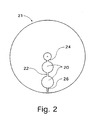
- Fig. 2 shows a top view of the structure of Fig. 1 in case the microstructure comprises channels and chambers;
- Fig. 3a is a cross section through a channel of a micro channel structure wherein a plug of a stimuli responsive gel is located in a channel, without being anchored to any surface, and in a swollen state;
- Fig. 3b is the same cross section as in Fig. 3a, where the polymer has been stimulated to collapse, thereby providing a free flow path;
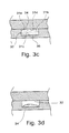
- Fig. 3c is a cross section through a channel of a micro channel structure wherein a plug of a stimuli responsive gel is anchored in one surface of the channel, and in a swollen state;
- Fig. 3d is the same cross section as in Fig. 3a, where the polymer has been stimulated to collapse, thereby providing a free flow path;
- Fig. 3e shows a cross section of a channel in which the polymer has been anchored to three surfaces of a channel, and is in a contracted state;
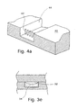
- Fig. 4a is a perspective view, partially in cross section of a channel having a grid as a mechanical means to prevent a gel plug from moving;
- Fig. 4b is a perspective view, partially in cross section, of a channel having a plurality of pointed protrusions provided over a surface of a channel, providing anchoring means to prevent a gel plug from moving;
- Fig. 4c is a perspective view, partially in cross section of a channel having side rooms in which a gel plug can be inserted, to prevent it from moving;
- Fig. 5a is microphotograph of the gel prepared in Example 1 in a swollen state; and
- Fig. 5b is the same gel as shown in Fig. 5a in contracted state.
-
- For the purposes of this application, the term "chemical reactor" shall be taken to mean any structure capable of housing chemical and/or biological reagents or reaction partners, and in which these agents can react, i.e. interact with each other, for the purposes of synthesis, analysis, separation or other chemical, physical-chemical or biological processes.
- In Fig. 1 there is shown a cross section of a microfabricated channel structure, which forms the subject matter of WO 94/29400.
- The structure in Fig. 1 comprises two
elements open channels 14 and or cavities provided therein. The bonding may be effected by applying athin layer 13 of a solution of a material capable of fusing with and having a lower melting point than that of the materials of the two element surfaces, in a solvent which substantially does not dissolve the element surface material or materials. Solvent is removed, the element surface are brought together and heated to melt the layer 3 so as to bond the surfaces together. - In Fig. 2 a top view of a simplified, exemplary CD (compact disk) type of
device 21 is shown, having a chamber and channel structure that may be made e.g. in accordance with the disclosure of WO 94/29400. - Thus, the disk comprises two
chambers 20 connected via achannel 22. There is also provided aninlet channel 24 having an upward opening (not shown) for the introduction of reagents, and anoutlet channel 26, having an opening (not shown) for the discharge of reacted material. - This particular configuration could be used for e.g. performing a sequential reaction in two steps, one in each
chamber 20, the first step being carried out in the innermost (with respect to the radial direction) chamber, and the second in the outermost chamber. This structure thus constitutes a "chemical reactor" as defined above, e.g. for carrying out a synthetic reaction. However, in order to be able to do this in a controlled way, a valve function according to the invention is provided in at least the connectingchannel 22 and theoutlet channel 26. Thereby the second chamber can be isolated from the first, and the reaction in the first chamber can be carried out to the desired extent. Thereafter the valve is activated and the reaction mixture in the first chamber can be transported into the second chamber where new reagents may be present and the second step is carried out. - The driving force for the transport of material between the chamber can be a centrifugal field created by spinning the disk. For electrophoresis applications, an electric field would be employed.
If a column like configuration is employed, i.e. the chambers are arranged vertically, the first above the second, gravity could be used as driving force for the transport. - Now the valve function according to the invention will be described in detail with reference to Figs 3a-3e.
- According to a first embodiment of the invention (Figs. 3a and 3b), a
polymer 34 capable of effecting a structural change in response to a stimulus (stimulus responsive polymer), is placed in achannel 32 in a channel and chamber micro structure of the type described above. When exposed to said stimulus, the polymer will collapse or contract, and leave at least a fraction of the channel in which it is situated free for liquid to flow there through - According to another embodiment of the invention, a polymer capable of effecting a structural change in response to a stimulus, is anchored in a
channel 32 in a channel and chamber micro structure of the type described above. The polymer is anchored in such a way that when stimulated to collapse or contract, it has the possibility to leave at least a fraction of the channel in which it is situated free for liquid to flow through. Normally the cross section of the channels will be rectangular (see Fig. 3c), that is there will be fourwalls 31a-d, essentially perpendicular to each other. For a configuration of this type, thepolymer 34 would preferably be anchored (schematically indicated at 36) to one, two or even three of the walls in said channel. This is shown schematically in Fig. 3c, where the polymer is shown to be in its swollen state, thereby blocking the channel completely. In fig. 3d a situation is shown where the polymer has been stimulated, e.g. by heating, such that it collapses, thereby opening thechannel 32 to liquid flow. Finally, in Fig. 3e an embodiment is shown where thepolymer gel 34 has been anchored in three walls of a channel. When stimulated by e.g. heat, the polymer strives to contract, but since it is attached to the walls on three sides, it will form a concave upper surface, leaving afree pathway 32 for fluid flow. - There are two main alternatives for bonding the stimulus-responsive polymer to the channel wall:
- (a) chemical bonding/anchoring including covalent attachment or physical adsorption (for instance via ionic forces, van der Waals forces, dipole-dipole interactions etc, and
- (b) retainment by mechanical means, for instance in chambers with narrow outlets and/or inlets (obstructions). Alternative (a) requires that the polymer material is only partially bonded to the channel surface, i.e. there should be a non-bonded part leaving a free fluid pathway between the polymer material and the channel surface when the polymer material is in a contracted state. Thus, this variant requires that bonding is occurring only on a fraction of the contact area between the microchannel surface and the plug in a swelled state.
-
- The stimulus-responsive polymer may be bonded to the channel wall e.g. by effecting cross-linking reaction between polymer units of the wall material and the stimulus-responsive polymer respectively (= covalent anchoring/attachment/bonding). There are many ways of anchoring the polymer available to the skilled man, a couple of which are given as non-limiting examples below.
- 1) For polymers prepared by radical polymerization (e.g.
polyacrylamides, polyacrylates, polymethacrylates or
polyvinylamides) the channel surface can be modified to contain
reactive groups capable of participating in the polymerization. Such
groups can be active as initiators (e.g. azo or peroxide groups),
copolymerizable groups (e.g. double bonds) or chain transfer groups
(e.g. thiols or tertiary amines). Examples of ways to introduce the
reactive groups are listed below:
- reacting glass, silica or silicon surfaces with a methacryl silane, a vinyl silane or a thiol silane.
- coating various surfaces with a thin layer of a polymer containing double bonds, such as allyl glycidyl agarose, polybutadiene or an unsaturated polyester resin.
- subjecting the polymer surfaces to plasma (glow discharge) treatment under such conditions that double bonds are formed on the surface.
- 2) More generally applicable ways could be to provide a rough surface with possibilities for mechanical interlocking of the polymer or to create an interpenetrating polymer network in the interphase between the polymer and a polymeric substrate.
-
- It is also possible to use mechanical means to retain the polymer gel in a fixed position. These options will be described further in the Examples below.
- The material in said micro channel surface can be subjected to a variety of surface treatments, such as wet etching, plasma treatment, corona treatment, UV treatment, grafting, adsorption coating, in order to improve the surface properties.
- The stimulus, which can cause a structural change of the polymer in the pores, is selected from pH, ion, solvent composition, chemical substance, heat, electricity and light such as ultraviolet radiation. The structural change of polymer is swelling and contraction. The invention utilizes the nature of intelligent polymers that an external stimulus can trigger a reversible structural change between a solvated state and a desolvated state.
- An important feature of the polymers used in the valves of the present invention is that they switch from a swelled state (solvated state) to contracted state (desolvated state) or vice versa in a reversible manner as discussed elsewhere herein. Thus the state at hand is dependent on the level/intensity of a stimulus applied, meaning for instance that above a certain critical level/intensity (magnitude) of the stimulus one state is at hand. For chemical substances the level/intensity typically corresponds to concentrations. When going below the critical level, the polymer is transformed to the other state. For a thermo-responsive polymer having a lower critical solution temperature (LCST), an increase in temperature passing the LCST will cause a switch from the solvated to the desolvated state and vice versa when changing the temperature in the opposite direction. When using a polymer having an upper critical solution temperature (UCST) the temperature increase will result in a switch from a desolvated state to a solvated state.
- For example, a polymeric electrolyte gel is known to undergo a structural change owing to an osmotic pressure change by electrolyte ions in the polymer chain and interaction of electrolyte ions with a solvent. Then the polymeric electrolyte gel undergoes reversible contraction in response to a change of pH, solvent composition and ion concentration. An electric stimulus (in terms of potential, voltage and current) can be effectively utilized for the polymers contraction response since it can bring a local change of pH or ion concentration. Among non-ionic polymers, e.g. polymers and copolymers of vinyl methyl ether and N-isopropylacrylamide undergo a change between hydrophilic and hydrophobic states in response to heat and provide a contraction response in an aqueous solvent. Then by utilizing heat generation by electric resistance or heat of mixing, the effective diameter of the pores can be changed. A stimulus given by a chemical substance is such that polymer chains swollen in pores are contracted if a complex is formed by utilizing hydrogen bonds or the like. For example, if a carboxylic polymer swollen in pores is contacted with an agent containing a polyether, the polycarboxylic acid reacts with the polyether to form a high molecular weight complex with concomitant contraction, resulting in the pores increasing an open passage for fluids. The valves according to the invention are provided at selected points in a micro channel system. They can be prepared e.g. by photopolymerizing the stimulus responsive polymer in situ, where the irradiation is made through a mask, such that the polymer is only formed in the illuminated areas. After e.g. heat contraction of the polymer, residual monomers can be washed out of the channel system. It is also conceivable as an alternative to irradiation with light to employ microwaves, electron beams or any other type of radiation that is possible to mask off.
- A further conceivable method is to form the polymer in the entire channel system, and then selectively degrading it (e.g. by light or radiation) everywhere except in the designated areas. The degradation products would then be washed out after contraction of the valve areas.
- The invention will now be illustrated by way of the following non-limiting examples.
- In the following Examples a CD (compact disk) type device comprising micro channels and chambers as shown schematically in Fig. 2 can be used.
- N-isopropylacrylamide (0.5 g) and N,N-methylene bisacrylamide (0.01 g) was dissolved in water (4.0 ml). 0,1 ml of a photo-initiator (
Irgacure 184, Ciba-Geigy, 100 mM in ethylene glycol) was then diluted in 0.5 ml water, before mixing it with the monomer solution. A drop of the monomer solution was transferred to a channel in a microfabricated CD disc made of plastic (polycarbonate), and covered by a microscope glass cover slip. The monomer solution inside the channel was then illuminated with UV light through the glass cover slip for 10 minutes in order to polymerize the monomers . - When the polymerization was completed, a hydrostatic pressure using an aqueous dye solution was applied to the inlet of the channel. No liquid was seen to flow through the channel (see Fig. 5a). The CD disc was then left at 40°C for 5 minutes, and a hydrostatic pressure was again applied to the channel. This time the liquid immediately flowed through the channel (see Fig. 5b). The CD disc was then allowed to return to room temperature, and again a hydrostatic pressure was applied. No liquid flowed through the channel. A picture of the valve before and after heat treatment is shown in Fig. 5a and 5b respectively.
- A microscope cover glass was wiped with methacryloxytriethoxysilane and rinsed with water and ethanol. A gel-forming solution was prepared from 0.5 g N,N-diethylacrylamide, 10 mg N,N'-methylenebisacrylamide, 6.5 ml distilled water and 0.1 ml of a 0.1 M solution of Irgacure-184 in ethylene glycol. A droplet of this solution was placed in a channel of a polycarbonate CD disc having a recessed 100 µm deep channel pattern on its surface, and a microscope cover glass was placed over the droplet with the treated side facing downwards. The package was placed on a cold steel plate under an array of low pressure mercury lamps and illuminated for 5 min to polymerize the monomers. A transparent gel was formed in the channels, which turned opaque upon heating to 45°C, and again turned transparent when it was cooled below room temperature. An aqueous dye solution was able to penetrate the channel system at 45°C, thus proving that a free path-way for fluid flow was provided. At room temperature the channel was blocked and no dye solution penetrated. The cover glass was then pryed.
- A gel-forming solution was prepared from 0,5 g N,N-diethylacrylamide, 10 mg N,N'-methylenebisacrylamide, 6,5 ml distilled water and 0,1 ml of a o,1 M solution of Irgacure-184 in ethylene glycol. A droplet of this solution was placed in a channel of a polycarbonate CD disc having a recessed 100 µm deep channel pattern on its surface, and a microscope cover glass was placed over the droplet. The package was placed on a cold steel plate under an array of low pressure mercury lamps and illuminated for 5 min to polymerize the monomers. A transparent gel was formed in the channels, which turned opaque upon heating to 45°C, and again turned transparent when it was cooled below room temperature. An aqueous dye solution was able to penetrate the channel system at 45°C, thus proving that a free path-way for fluid flow was provided. At room temperature the channel was blocked and no dye solution penetrated.
- The same procedure as in Example 2 was repeated, but the cover glass was partially masked with an aluminum mask during illumination. The thermo-responsive gel was formed only in the illuminated parts of the channel system.
- A micro channel structure in a
microfabricated CD disc 40 made of plastic (polycarbonate) is made, having the structure as shown schematically in perspective in Fig. 4. In this case there are provided mechanical obstructions in thechannel 44 at the points where the valve is desired. These obstructions can be in the form of a grid of vertically arranged pins 42, as shown in Fig. 4a which is a cross section through a substrate in which a channel having such obstructions has been made. The gel (not shown) is polymerized in the channel upstream of the grid, using the same procedure as in Example 1. - When the polymerization is completed, a hydrostatic pressure using an aqueous dye solution is applied at room temperature to the inlet of the channel. No liquid was seen to flow through the channel. The CD disc is then left at 40°C for 5 minutes, and a hydrostatic pressure is again applied to the channel. This time the liquid immediately flowed through the channel. The CD disc is then allowed to return to room temperature, and again a hydrostatic pressure is applied. No liquid flowed through the channel.
- A micro channel structure in a microfabricated CD disc made of plastic (polycarbonate) is made, having the structure as shown schematically in Fig. 4b. In this case there are provided mechanical obstructions in the form of
protrusions 46 in the channel, distributed over the area where the polymer plug is to be located, i.e. at the point where the valve is desired. These obstructions can be shaped in the same way as those shown in Fig. 4a, or could be shorter, rather like nipples, as shown in Fig. 4b, and will act as retaining elements for the gel. The gel is polymerized (not shown) in the channel in the area where the pins are located, using the same procedure as in Example 1. Thus, the pins will be molded inside the gel plug, thereby preventing it from moving in the channel. - When the polymerization is completed, a hydrostatic pressure using an aqueous dye solution is applied at room temperature to the inlet of the channel. No liquid is seen to flow through the channel. The CD disc is then left at 40°C for 5 minutes, and a hydrostatic pressure is again applied to the channel. This time the liquid immediately flowed through the channel. The CD disc is then allowed to return to room temperature, and again a hydrostatic pressure is applied. No liquid flowed through the channel.
- Of course other anchoring methods may be employed. One alternative is to provide a widened portion of the channel, such as the "side rooms" 48 as shown schematically in fig. 4c. A gel plug is provided such that it is "anchored" in the side rooms of the
channel 44. If the side rooms are made large enough, the plug will be effectively prevented from moving in the channel under hydrostatic pressure.
Claims (27)
- A method of controlling flow of liquids in a micro channel structure comprising a micro channel (32) and a chamber in the microformat, said microchannel structure defining a liquid transportation system that is present on a plate comprising one or more of said liquid transportation systems, characterized in comprising the steps of:providing in at least one position, and preferably in a plurality of positions in said micro channel structure a plug of polymer material in each said position, said polymer material (34) comprising an intelligent polymer having the property of responding to externally applied energy by changing its volume, said polymer material in a first state providing a first volume blocking said channel from liquid flow, and in a second state providing a second volume giving a free path-way for liquid flow; andselectively applying energy of appropriate type and magnitude to the polymer material of a selected one of said at least one plug so as to cause the volume change between said two states, thereby bringing said polymer to a desired one of said first or second states.
- The method of claim 1, wherein said microchannel and chamber is defined between two planar surfaces that are applied to each other.
- The method of anyone of claims 1-2, characterized in said intelligent polymer being selected from the group of polymers consisting of heat responsive polymers, light responsive polymers, magnetically responsive polymers, pH responsive polymers and polymers responsive to electric fields.
- The method of anyone of claims 1-3, characterized in the polymer material (32) at least partially being anchored to a surface inside said micro channel (34).
- The method of anyone of claims 1-4, characterized in the polymer material (32) being chemically bonded to a surface inside said micro channel.
- The method of anyone of claims 1-3, characterized in the polymer material being anchored in the micro channel (34) by means of a mechanical obstruction (42,46) in the microchannel.
- The method of any preceding claim, characterized in the material in said micro channel surface comprising a material selected from plastics; rubbers; metals; carbon; inorganic oxides, nitrides, carbides; silicon; quartz.
- The method of claim 7, characterized in the material being plastics selected amongst polycarbonates, polystyrenes, and cycloolefin polymers.
- The method of any of claims 4-8, characterized in the material in said micro channel surface having been subjected to a surface treatment selected amongst wet etching, plasma treatment, corona treatment, UV treatment, grafting, adsorption and coating.
- The method of any preceding claim, characterized in the step of applying energy comprising heating the polymer material and the polymer material comprises a heat responsive polymer.
- The method of claim 10, characterized in said heating being performed by irradiating with electromagnetic radiation.
- The method of any of claims 1-9, characterized in the polymer being light sensitive and the step of applying energy comprising illuminating the polymer material with light of a suitable wave length, and the polymer material comprising a light responsive polymer.
- The method of any of claims 1-9, characterized in the step of applying energy comprising exposing the polymer material to a magnetic field, and the polymer material comprises a magnetically responsive polymer.
- The method of any of claims 1-9, characterized in the step of applying energy comprising exposing the polymer material to an electric field, and the polymer material comprises a polymer responsive to electricity.
- A micro channel valve system, characterized in comprising a plurality of plugs (34) of a polymer material comprising an intelligent polymer having the property of responding to externally applied energy by changing its volume, said plugs being provided at selected locations within at least one channel (31a-d) of a micro channel structure (20, 22, 24, 26) comprising the channel and a chamber in the microformat, said microchannel structure defining a liquid transportation system that is present on a plate comprising one or more of said liquid transportation systems.
- The valve system of claim 15 wherein said chamber and channel is defined between to planar surfaces that are applied to each other.
- The valve system according to any of claims 15-16, characterized in said intelligent polymer being selected from the group of polymers consisting of heat responsive polymers, light responsive polymers, magnetically responsive polymers, polymers responsive to electric fields and pH-responsive polymers.
- The valve system according to any of claims 15-17, characterized in said intelligent polymer being selected from the group of polymers consisting of polyvinylethers, polyacrylamides, polyvinylamides, polyalkyleneglycols, celluloseethers, polyacrylates, polymethacrylates; and polymers of N,N-diethylacrylamide, N,N-diethylbisacrylamide, N-vinylcaprolactam, and a polymer obtained by the polymerization of N-isopropylacrylamide and N,N-methylene bisacrylamide.
- The valve system according to any of claims 15-19, characterized in said polymer material being anchored inside said micro channel by chemical bonding.
- The valve system according to any of claims 15-19, characterized in said polymer plug being anchored only over a fraction of the contact surface between the plug in a swelled state and the inner surface of said micro channel.
- The valve system according to any of claims 15-19, characterized in said polymer plug being retained in a fixed position inside said micro channel by mechanical means.
- A chemical reactor, characterized in comprising a plurality of micro chambers (20) interconnected by micro channels 22, 24, 26) that are part of a liquid transportation system having a valve system which comprises a plurality of plugs of a polymer material comprising an intelligent polymer responding to externally applied energy by changing its volume, said plugs being provided at selected locations within at least one of said micro channels.
- The chemical reactor of claim 22, characterized in said intelligent polymer being selected from the group of polymers consisting of heat responsive polymers, light responsive polymers, magnetically responsive polymers, polymers responsive to electric fields and pH-responsive polymers.
- The chemical reactor as claimed in any of claims 22-23, characterized in said chambers and channels being provided in a planar substrate (21).
- The chemical reactor as claimed in claim 24, characterized in the substrate being of a material selected from the group consisting of plastics; rubbers; metals; carbon; inorganic oxides, nitrides, carbides; silicon; quartz.
- The chemical reactor as claimed in any of claims 22-25, characterized in the substrate being circular.
- The chemical reactor as claimed in any of claims 22-25, characterized in the substrate being rectangular.
Applications Claiming Priority (3)
| Application Number | Priority Date | Filing Date | Title |
|---|---|---|---|
| SE9902474A SE9902474D0 (en) | 1999-06-30 | 1999-06-30 | Polymer valves |
| SE9902474 | 1999-06-30 | ||
| PCT/EP2000/006142 WO2001002737A1 (en) | 1999-06-30 | 2000-06-30 | Polymer valves |
Publications (2)
| Publication Number | Publication Date |
|---|---|
| EP1194696A1 EP1194696A1 (en) | 2002-04-10 |
| EP1194696B1 true EP1194696B1 (en) | 2003-12-10 |
Family
ID=20416294
Family Applications (1)
| Application Number | Title | Priority Date | Filing Date |
|---|---|---|---|
| EP00945858A Expired - Lifetime EP1194696B1 (en) | 1999-06-30 | 2000-06-30 | Polymer valves |
Country Status (8)
| Country | Link |
|---|---|
| US (1) | US7104517B1 (en) |
| EP (1) | EP1194696B1 (en) |
| JP (1) | JP4323743B2 (en) |
| AT (1) | ATE256254T1 (en) |
| AU (1) | AU5980800A (en) |
| DE (1) | DE60007128T2 (en) |
| SE (1) | SE9902474D0 (en) |
| WO (1) | WO2001002737A1 (en) |
Families Citing this family (71)
| Publication number | Priority date | Publication date | Assignee | Title |
|---|---|---|---|---|
| GB9808836D0 (en) | 1998-04-27 | 1998-06-24 | Amersham Pharm Biotech Uk Ltd | Microfabricated apparatus for cell based assays |
| SE9902474D0 (en) | 1999-06-30 | 1999-06-30 | Amersham Pharm Biotech Ab | Polymer valves |
| KR100677860B1 (en) * | 1999-07-23 | 2007-02-05 | 보드 오브 트러스티스 오브 유니버스티 오브 일리노이즈 | Microfabricated Devices and Method of Manufacturing The Same |
| SE0001790D0 (en) * | 2000-05-12 | 2000-05-12 | Aamic Ab | Hydrophobic barrier |
| US7026131B2 (en) | 2000-11-17 | 2006-04-11 | Nagaoka & Co., Ltd. | Methods and apparatus for blood typing with optical bio-discs |
| US7087203B2 (en) | 2000-11-17 | 2006-08-08 | Nagaoka & Co., Ltd. | Methods and apparatus for blood typing with optical bio-disc |
| SE0004296D0 (en) | 2000-11-23 | 2000-11-23 | Gyros Ab | Device and method for the controlled heating in micro channel systems |
| US7079468B2 (en) | 2000-12-08 | 2006-07-18 | Burstein Technologies, Inc. | Optical discs for measuring analytes |
| US7054258B2 (en) | 2000-12-08 | 2006-05-30 | Nagaoka & Co., Ltd. | Optical disc assemblies for performing assays |
| US7091034B2 (en) | 2000-12-15 | 2006-08-15 | Burstein Technologies, Inc. | Detection system for disk-based laboratory and improved optical bio-disc including same |
| US7429354B2 (en) | 2001-03-19 | 2008-09-30 | Gyros Patent Ab | Structural units that define fluidic functions |
| EP1384076B1 (en) | 2001-03-19 | 2012-07-25 | Gyros Patent Ab | Characterization of reaction variables |
| EP1493014A2 (en) | 2001-04-11 | 2005-01-05 | Burstein Technologies, Inc. | Multi-parameter assays including analysis discs and methods relating thereto |
| US6523559B2 (en) * | 2001-07-27 | 2003-02-25 | Wisconsin Alumni Research Foundation | Self-regulating microfluidic device and method of using the same |
| EP2269736B1 (en) | 2001-08-28 | 2013-04-24 | Gyros Patent Ab | Retaining microfluidic microcavity and other microfluidic structures |
| US6919058B2 (en) * | 2001-08-28 | 2005-07-19 | Gyros Ab | Retaining microfluidic microcavity and other microfluidic structures |
| US6532997B1 (en) | 2001-12-28 | 2003-03-18 | 3M Innovative Properties Company | Sample processing device with integral electrophoresis channels |
| JP4083452B2 (en) * | 2002-03-28 | 2008-04-30 | 旭化成株式会社 | Valve mechanism |
| AU2003216002A1 (en) * | 2002-03-31 | 2003-10-13 | Gyros Ab | Efficient mmicrofluidic devices |
| JP4050971B2 (en) * | 2002-10-08 | 2008-02-20 | 株式会社島津製作所 | Valve with filter function using diaphragm |
| WO2004051229A1 (en) * | 2002-12-02 | 2004-06-17 | Nec Corporation | Liquid switch, and microchip and mass-analyzing system using the same |
| CN101158447B (en) * | 2002-12-04 | 2012-12-26 | 斯宾克斯公司 | Devices and methods for programmable microscale manipulation of fluids |
| EP1594798B1 (en) | 2003-01-30 | 2018-12-19 | Gyros Patent Ab | Inner walls of microfluidic devices |
| SE0300823D0 (en) | 2003-03-23 | 2003-03-23 | Gyros Ab | Preloaded Microscale Devices |
| JPWO2004097393A1 (en) * | 2003-04-28 | 2006-07-13 | 松下電器産業株式会社 | Filter and biosensor equipped with the filter |
| WO2004103891A1 (en) | 2003-05-23 | 2004-12-02 | Gyros Patent Ab | Fluidic functions based on non-wettable surfaces |
| FR2856046B1 (en) * | 2003-06-16 | 2005-07-29 | Biomerieux Sa | FLUIDIC MICROVANNE WITH OPENING BY ELECTRICAL CONTROL |
| US7390464B2 (en) | 2003-06-19 | 2008-06-24 | Burstein Technologies, Inc. | Fluidic circuits for sample preparation including bio-discs and methods relating thereto |
| US7238269B2 (en) | 2003-07-01 | 2007-07-03 | 3M Innovative Properties Company | Sample processing device with unvented channel |
| FR2857427B1 (en) * | 2003-07-10 | 2005-08-26 | Biomerieux Sa | ELECTRICALLY CONTROLLED VALVE COMPRISING A MICROPOROUS MEMBRANE |
| WO2005036182A1 (en) * | 2003-10-15 | 2005-04-21 | Matsushita Electric Industrial Co., Ltd. | Method of passing fluid in capillary chip |
| US20090010819A1 (en) * | 2004-01-17 | 2009-01-08 | Gyros Patent Ab | Versatile flow path |
| WO2006075966A1 (en) * | 2005-01-17 | 2006-07-20 | Gyros Patent Ab | A versatile flow path |
| SE0400181D0 (en) | 2004-01-29 | 2004-01-29 | Gyros Ab | Segmented porous and preloaded microscale devices |
| US7548092B2 (en) | 2004-02-25 | 2009-06-16 | Ternarylogic Llc | Implementing logic functions with non-magnitude based physical phenomena |
| US7696785B2 (en) * | 2004-02-25 | 2010-04-13 | Ternarylogic Llc | Implementing logic functions with non-magnitude based physical phenomena |
| JP4516346B2 (en) * | 2004-04-14 | 2010-08-04 | 積水化学工業株式会社 | Micro total analysis system |
| US7313917B2 (en) * | 2004-07-01 | 2008-01-01 | Cornell Research Foundation, Inc. | Volume phase transition to induce gel movement |
| US20100164548A1 (en) * | 2004-09-08 | 2010-07-01 | Ternarylogic Llc | Implementing Logic Functions With Non-Magnitude Based Physical Phenomena |
| US20060093528A1 (en) | 2004-10-18 | 2006-05-04 | Applera Corporation | Device including a dissolvable structure for flow control |
| KR100682920B1 (en) * | 2005-01-20 | 2007-02-15 | 삼성전자주식회사 | Microfluidic chip for multiple bioassay and its method for production |
| KR100668335B1 (en) * | 2005-04-02 | 2007-01-12 | 삼성전자주식회사 | Microvalve having ferromagnetic wax plug and flux control method using ferromagnetic wax |
| EP1790861A1 (en) * | 2005-11-25 | 2007-05-30 | Bonsens AB | Microfluidic system |
| GB0602743D0 (en) * | 2006-02-10 | 2006-03-22 | Inverness Medical Switzerland | Microfluidic device |
| US7998433B2 (en) * | 2006-04-04 | 2011-08-16 | Samsung Electronics Co., Ltd. | Valve unit and apparatus having the same |
| KR100738113B1 (en) * | 2006-05-10 | 2007-07-12 | 삼성전자주식회사 | Phase transition type valve and the manufacturing method thereof |
| US7897113B2 (en) * | 2006-07-17 | 2011-03-01 | Industrial Technology Research Institute | Fluidic devices and controlling methods thereof |
| EP1884284A1 (en) * | 2006-08-04 | 2008-02-06 | Samsung Electronics Co., Ltd. | Closing valve unit and reaction apparatus having closing valve |
| US8464760B2 (en) | 2006-08-16 | 2013-06-18 | Samsung Electronic Co., Ltd. | Valve unit, reaction apparatus with the same, and method of forming valve in channel |
| KR100818274B1 (en) | 2006-09-05 | 2008-04-01 | 삼성전자주식회사 | Apparatus and method of controlling the microfluidic system, and the microfluidic system |
| KR100846501B1 (en) | 2006-11-09 | 2008-07-17 | 삼성전자주식회사 | Valve unit and fluid treating apparatus with the same |
| US8414848B2 (en) * | 2007-05-10 | 2013-04-09 | Panasonic Corporation | Substrate including channel part having chamber, and multistage liquid feed device comprising the same |
| US20090081768A1 (en) * | 2007-09-21 | 2009-03-26 | Applera Corporation | Devices and Methods for Thermally Isolating Chambers of an Assay Card |
| GB2457094A (en) * | 2008-02-04 | 2009-08-05 | Univ Dublin City | A cuvette assembly for holding milking samples |
| US20100069821A1 (en) * | 2008-09-16 | 2010-03-18 | Searete Llc, A Limited Liability Corporation Of The State Of Delaware | Ex vivo modifiable medicament release-sites final dosage form |
| US20100068254A1 (en) * | 2008-09-16 | 2010-03-18 | Mahalaxmi Gita Bangera | Modifying a medicament availability state of a final dosage form |
| US20100068275A1 (en) * | 2008-09-16 | 2010-03-18 | Searete Llc, A Limited Liability Corporation Of The State Of Delaware | Personalizable dosage form |
| US20100068235A1 (en) * | 2008-09-16 | 2010-03-18 | Searete LLC, a limited liability corporation of Deleware | Individualizable dosage form |
| US20100068153A1 (en) * | 2008-09-16 | 2010-03-18 | Searete Llc, A Limited Liability Corporation Of The State Of Delaware | Ex vivo activatable final dosage form |
| US20100068256A1 (en) * | 2008-09-16 | 2010-03-18 | Searete Llc, A Limited Liability Corporation Of The State Of Delaware | Ex vivo modifiable medicament release-substance |
| US20100069887A1 (en) * | 2008-09-16 | 2010-03-18 | Searete Llc, A Limited Liability Corporation Of The State Of Delaware | Multiple chamber ex vivo adjustable-release final dosage form |
| DE102009023429B4 (en) | 2009-05-29 | 2013-08-14 | Siemens Aktiengesellschaft | Valve for lab-on-a-chip systems, method for actuating and producing the valve |
| KR101130698B1 (en) * | 2009-11-03 | 2012-04-02 | 삼성전자주식회사 | Valve unit, microfluidic device including the same, and driving method of the valve unit |
| JP5765729B2 (en) * | 2011-01-11 | 2015-08-19 | 学校法人 関西大学 | Molded product formed with photoresponsive polymer and use thereof |
| CA2902027A1 (en) | 2013-02-20 | 2014-08-20 | Crane Engineering, Inc. | Self-obstructing flammable fluid carrying conduit |
| WO2015173543A1 (en) * | 2014-05-12 | 2015-11-19 | University Of Southampton | Fluid flow device with flow control and method for making the same |
| US9993819B2 (en) | 2014-12-30 | 2018-06-12 | Stmicroelectronics S.R.L. | Apparatus for actuating and reading a centrifugal microfluidic disk for biological and biochemical analyses, and use of the apparatus |
| DE102015204235B4 (en) * | 2015-03-10 | 2016-12-15 | Fraunhofer-Gesellschaft zur Förderung der angewandten Forschung e.V. | Fluidic structure with holding section and method for uniting two fluid volumes |
| WO2017201122A2 (en) * | 2016-05-18 | 2017-11-23 | Crane, Thomas R. | Thermally activated flow stop valve |
| JP2021132569A (en) * | 2020-02-26 | 2021-09-13 | 横河電機株式会社 | Diffusion control mechanism and production method thereof |
| ES2887874B2 (en) * | 2020-06-23 | 2022-11-18 | Consejo Superior Investigacion | MICROFLUIDIC VALVE, MANUFACTURING PROCEDURE AND ITS USES |
Family Cites Families (57)
| Publication number | Priority date | Publication date | Assignee | Title |
|---|---|---|---|---|
| US4585652A (en) * | 1984-11-19 | 1986-04-29 | Regents Of The University Of Minnesota | Electrochemical controlled release drug delivery system |
| US4874500A (en) * | 1987-07-15 | 1989-10-17 | Sri International | Microelectrochemical sensor and sensor array |
| US5062841A (en) * | 1988-08-12 | 1991-11-05 | The Regents Of The University Of California | Implantable, self-regulating mechanochemical insulin pump |
| JPH05205984A (en) * | 1992-01-27 | 1993-08-13 | Nec Corp | Laminated solid electrolytic capacitor |
| WO1994017538A2 (en) | 1993-01-21 | 1994-08-04 | Mayo Foundation For Medical Education And Research | Microparticle switching devices |
| US5290240A (en) * | 1993-02-03 | 1994-03-01 | Pharmetrix Corporation | Electrochemical controlled dispensing assembly and method for selective and controlled delivery of a dispensing fluid |
| US5417235A (en) * | 1993-07-28 | 1995-05-23 | Regents Of The University Of Michigan | Integrated microvalve structures with monolithic microflow controller |
| US5368704A (en) * | 1993-08-06 | 1994-11-29 | Teknekron Corporation | Micro-electrochemical valves and method |
| JP3403233B2 (en) | 1994-01-20 | 2003-05-06 | テルモ株式会社 | Balloon catheter |
| JP2682478B2 (en) * | 1994-12-12 | 1997-11-26 | 日本電気株式会社 | Chip-shaped solid electrolytic capacitor and manufacturing method thereof |
| US5797898A (en) * | 1996-07-02 | 1998-08-25 | Massachusetts Institute Of Technology | Microchip drug delivery devices |
| SE9602638D0 (en) | 1996-07-03 | 1996-07-03 | Pharmacia Biotech Ab | An improved method for the capillary electrophoresis of nucleic acids, proteins and low molecular charged compounds |
| DE19749011A1 (en) * | 1996-11-19 | 1998-05-20 | Lang Volker | Micro=valve for one time use has opening closed by plug mounted on resistance plate |
| US5932799A (en) * | 1997-07-21 | 1999-08-03 | Ysi Incorporated | Microfluidic analyzer module |
| US6015266A (en) * | 1997-08-27 | 2000-01-18 | Baker Hughes Incorporated | Reactive material reciprocating submersible pump |
| US5984197A (en) * | 1998-02-12 | 1999-11-16 | C. Alan Sugarek | Thermostat |
| GB9808836D0 (en) | 1998-04-27 | 1998-06-24 | Amersham Pharm Biotech Uk Ltd | Microfabricated apparatus for cell based assays |
| GB9809943D0 (en) | 1998-05-08 | 1998-07-08 | Amersham Pharm Biotech Ab | Microfluidic device |
| US20040202579A1 (en) | 1998-05-08 | 2004-10-14 | Anders Larsson | Microfluidic device |
| SE9803734D0 (en) | 1998-10-30 | 1998-10-30 | Amersham Pharm Biotech Ab | Liquid handling system |
| GB9828785D0 (en) | 1998-12-30 | 1999-02-17 | Amersham Pharm Biotech Ab | Sequencing systems |
| US7261859B2 (en) | 1998-12-30 | 2007-08-28 | Gyros Ab | Microanalysis device |
| SE9901100D0 (en) | 1999-03-24 | 1999-03-24 | Amersham Pharm Biotech Ab | Surface and tis manufacture and uses |
| SE9901306D0 (en) | 1999-04-09 | 1999-04-09 | Amersham Pharm Biotech Ab | Improved TIRF chamber |
| US6406605B1 (en) * | 1999-06-01 | 2002-06-18 | Ysi Incorporated | Electroosmotic flow controlled microfluidic devices |
| SE9902474D0 (en) | 1999-06-30 | 1999-06-30 | Amersham Pharm Biotech Ab | Polymer valves |
| GB2355717A (en) | 1999-10-28 | 2001-05-02 | Amersham Pharm Biotech Uk Ltd | DNA isolation method |
| SE9903919D0 (en) | 1999-10-29 | 1999-10-29 | Amersham Pharm Biotech Ab | Device for dispensing droplets |
| SE9904802D0 (en) | 1999-12-23 | 1999-12-23 | Amersham Pharm Biotech Ab | Microfluidic surfaces |
| US6884395B2 (en) | 2000-05-12 | 2005-04-26 | Gyros Ab | Integrated microfluidic disc |
| SE0000300D0 (en) | 2000-01-30 | 2000-01-30 | Amersham Pharm Biotech Ab | Microfluidic assembly, covering method for the manufacture of the assembly and the use of the assembly |
| SE0001790D0 (en) | 2000-05-12 | 2000-05-12 | Aamic Ab | Hydrophobic barrier |
| US6431212B1 (en) * | 2000-05-24 | 2002-08-13 | Jon W. Hayenga | Valve for use in microfluidic structures |
| SE0004297D0 (en) | 2000-11-23 | 2000-11-23 | Gyros Ab | Device for thermal cycling |
| SE0004296D0 (en) | 2000-11-23 | 2000-11-23 | Gyros Ab | Device and method for the controlled heating in micro channel systems |
| US20040099310A1 (en) | 2001-01-05 | 2004-05-27 | Per Andersson | Microfluidic device |
| US6653625B2 (en) | 2001-03-19 | 2003-11-25 | Gyros Ab | Microfluidic system (MS) |
| EP1384076B1 (en) | 2001-03-19 | 2012-07-25 | Gyros Patent Ab | Characterization of reaction variables |
| US6717136B2 (en) | 2001-03-19 | 2004-04-06 | Gyros Ab | Microfludic system (EDI) |
| CA2442342A1 (en) | 2001-03-19 | 2002-09-26 | Gyros Ab | A microfluidic system (edi) |
| US7429354B2 (en) | 2001-03-19 | 2008-09-30 | Gyros Patent Ab | Structural units that define fluidic functions |
| US6919058B2 (en) | 2001-08-28 | 2005-07-19 | Gyros Ab | Retaining microfluidic microcavity and other microfluidic structures |
| DE60237289D1 (en) | 2001-09-17 | 2010-09-23 | Gyros Patent Ab | A CONTROLLED POWER IN A MICROFLUID DEVICE ENABLING FUNCTION UNIT |
| US20030054563A1 (en) | 2001-09-17 | 2003-03-20 | Gyros Ab | Detector arrangement for microfluidic devices |
| US20050214442A1 (en) | 2001-11-27 | 2005-09-29 | Anders Larsson | Surface and its manufacture and uses |
| US7238255B2 (en) | 2001-12-31 | 2007-07-03 | Gyros Patent Ab | Microfluidic device and its manufacture |
| US7221783B2 (en) | 2001-12-31 | 2007-05-22 | Gyros Patent Ab | Method and arrangement for reducing noise |
| AU2003216002A1 (en) | 2002-03-31 | 2003-10-13 | Gyros Ab | Efficient mmicrofluidic devices |
| US6955738B2 (en) | 2002-04-09 | 2005-10-18 | Gyros Ab | Microfluidic devices with new inner surfaces |
| US20050277195A1 (en) | 2002-04-30 | 2005-12-15 | Gyros Ab | Integrated microfluidic device (ea) |
| EP1509760A1 (en) | 2002-05-31 | 2005-03-02 | Gyros AB | Detector arrangement based on surface plasmon resonance |
| EP1608587B1 (en) | 2003-03-23 | 2016-11-23 | Gyros Patent Ab | Preloaded microscale devices |
| SE0300822D0 (en) | 2003-03-23 | 2003-03-23 | Gyros Ab | A collection of Micro Scale Devices |
| WO2004103891A1 (en) | 2003-05-23 | 2004-12-02 | Gyros Patent Ab | Fluidic functions based on non-wettable surfaces |
| US20050042770A1 (en) | 2003-05-23 | 2005-02-24 | Gyros Ab | Fluidic functions based on non-wettable surfaces |
| US7776272B2 (en) | 2003-10-03 | 2010-08-17 | Gyros Patent Ab | Liquid router |
| US8592219B2 (en) | 2005-01-17 | 2013-11-26 | Gyros Patent Ab | Protecting agent |
-
1999
- 1999-06-30 SE SE9902474A patent/SE9902474D0/en unknown
-
2000
- 2000-06-30 DE DE60007128T patent/DE60007128T2/en not_active Expired - Lifetime
- 2000-06-30 JP JP2001507943A patent/JP4323743B2/en not_active Expired - Lifetime
- 2000-06-30 WO PCT/EP2000/006142 patent/WO2001002737A1/en active IP Right Grant
- 2000-06-30 US US10/030,297 patent/US7104517B1/en not_active Expired - Lifetime
- 2000-06-30 AT AT00945858T patent/ATE256254T1/en not_active IP Right Cessation
- 2000-06-30 AU AU59808/00A patent/AU5980800A/en not_active Abandoned
- 2000-06-30 EP EP00945858A patent/EP1194696B1/en not_active Expired - Lifetime
Also Published As
| Publication number | Publication date |
|---|---|
| DE60007128T2 (en) | 2004-09-02 |
| AU5980800A (en) | 2001-01-22 |
| US7104517B1 (en) | 2006-09-12 |
| JP2003503716A (en) | 2003-01-28 |
| ATE256254T1 (en) | 2003-12-15 |
| EP1194696A1 (en) | 2002-04-10 |
| WO2001002737A1 (en) | 2001-01-11 |
| SE9902474D0 (en) | 1999-06-30 |
| DE60007128D1 (en) | 2004-01-22 |
| JP4323743B2 (en) | 2009-09-02 |
Similar Documents
| Publication | Publication Date | Title |
|---|---|---|
| EP1194696B1 (en) | Polymer valves | |
| US6375901B1 (en) | Chemico-mechanical microvalve and devices comprising the same | |
| US6951632B2 (en) | Microfluidic devices for introducing and dispensing fluids from microfluidic systems | |
| US8672532B2 (en) | Microfluidic methods | |
| US6787088B2 (en) | Controlled fluid transport in microfabricated polymeric substrates | |
| US7494555B2 (en) | Microfabricated elastomeric valve and pump systems | |
| US7216660B2 (en) | Method and device for controlling liquid flow on the surface of a microfluidic chip | |
| US7217367B2 (en) | Microfluidic chromatography | |
| CA2333618C (en) | Microfluidic device | |
| US7479186B2 (en) | Systems and methods for mixing reactants | |
| US9512935B2 (en) | Microchannel with an opening and/or closing and/or pumping device | |
| JP2002536640A (en) | Multi-channel control for microfluidic introduction | |
| JP2009001819A (en) | Polymer surface modification | |
| AU2923801A (en) | Biochannel assay for hybridization with biomaterial | |
| JP2004061320A (en) | Liquid sending method of micro fluid device | |
| JP2007170469A (en) | Temperature responsive valve and its manufacturing method | |
| EP1195523B1 (en) | Microfabricated elastomeric valve and pump systems | |
| WO2002098554A1 (en) | Integrated electrokinetic devices and methods of manufacture | |
| US20050178317A1 (en) | High throughput screening of crystallization of materials | |
| EP1557565B1 (en) | Microfabricated elastomeric valve and pump systems | |
| AU760310B2 (en) | Controlled fluid transport in microfabricated polymeric substrates | |
| Barrett | Polymers in microfluidics |
Legal Events
| Date | Code | Title | Description |
|---|---|---|---|
| PUAI | Public reference made under article 153(3) epc to a published international application that has entered the european phase |
Free format text: ORIGINAL CODE: 0009012 |
|
| 17P | Request for examination filed |
Effective date: 20011211 |
|
| AK | Designated contracting states |
Kind code of ref document: A1 Designated state(s): AT BE CH CY DE DK ES FI FR GB GR IE IT LI LU MC NL |
|
| AX | Request for extension of the european patent |
Free format text: AL;LT;LV;MK;RO;SI |
|
| RAP1 | Party data changed (applicant data changed or rights of an application transferred) |
Owner name: GYROS AB |
|
| 17Q | First examination report despatched |
Effective date: 20030214 |
|
| GRAH | Despatch of communication of intention to grant a patent |
Free format text: ORIGINAL CODE: EPIDOS IGRA |
|
| GRAS | Grant fee paid |
Free format text: ORIGINAL CODE: EPIDOSNIGR3 |
|
| GRAA | (expected) grant |
Free format text: ORIGINAL CODE: 0009210 |
|
| AK | Designated contracting states |
Kind code of ref document: B1 Designated state(s): AT BE CH CY DE DK ES FI FR GB GR IE IT LI LU MC NL |
|
| PG25 | Lapsed in a contracting state [announced via postgrant information from national office to epo] |
Ref country code: IT Free format text: LAPSE BECAUSE OF FAILURE TO SUBMIT A TRANSLATION OF THE DESCRIPTION OR TO PAY THE FEE WITHIN THE PRESCRIBED TIME-LIMIT;WARNING: LAPSES OF ITALIAN PATENTS WITH EFFECTIVE DATE BEFORE 2007 MAY HAVE OCCURRED AT ANY TIME BEFORE 2007. THE CORRECT EFFECTIVE DATE MAY BE DIFFERENT FROM THE ONE RECORDED. Effective date: 20031210 Ref country code: NL Free format text: LAPSE BECAUSE OF FAILURE TO SUBMIT A TRANSLATION OF THE DESCRIPTION OR TO PAY THE FEE WITHIN THE PRESCRIBED TIME-LIMIT Effective date: 20031210 Ref country code: BE Free format text: LAPSE BECAUSE OF FAILURE TO SUBMIT A TRANSLATION OF THE DESCRIPTION OR TO PAY THE FEE WITHIN THE PRESCRIBED TIME-LIMIT Effective date: 20031210 Ref country code: AT Free format text: LAPSE BECAUSE OF FAILURE TO SUBMIT A TRANSLATION OF THE DESCRIPTION OR TO PAY THE FEE WITHIN THE PRESCRIBED TIME-LIMIT Effective date: 20031210 Ref country code: CY Free format text: LAPSE BECAUSE OF FAILURE TO SUBMIT A TRANSLATION OF THE DESCRIPTION OR TO PAY THE FEE WITHIN THE PRESCRIBED TIME-LIMIT Effective date: 20031210 Ref country code: FI Free format text: LAPSE BECAUSE OF FAILURE TO SUBMIT A TRANSLATION OF THE DESCRIPTION OR TO PAY THE FEE WITHIN THE PRESCRIBED TIME-LIMIT Effective date: 20031210 |
|
| REG | Reference to a national code |
Ref country code: GB Ref legal event code: FG4D |
|
| REG | Reference to a national code |
Ref country code: CH Ref legal event code: EP |
|
| REG | Reference to a national code |
Ref country code: IE Ref legal event code: FG4D |
|
| REF | Corresponds to: |
Ref document number: 60007128 Country of ref document: DE Date of ref document: 20040122 Kind code of ref document: P |
|
| REG | Reference to a national code |
Ref country code: CH Ref legal event code: NV Representative=s name: ISLER & PEDRAZZINI AG |
|
| PG25 | Lapsed in a contracting state [announced via postgrant information from national office to epo] |
Ref country code: GR Free format text: LAPSE BECAUSE OF FAILURE TO SUBMIT A TRANSLATION OF THE DESCRIPTION OR TO PAY THE FEE WITHIN THE PRESCRIBED TIME-LIMIT Effective date: 20040310 Ref country code: DK Free format text: LAPSE BECAUSE OF FAILURE TO SUBMIT A TRANSLATION OF THE DESCRIPTION OR TO PAY THE FEE WITHIN THE PRESCRIBED TIME-LIMIT Effective date: 20040310 |
|
| PG25 | Lapsed in a contracting state [announced via postgrant information from national office to epo] |
Ref country code: ES Free format text: LAPSE BECAUSE OF FAILURE TO SUBMIT A TRANSLATION OF THE DESCRIPTION OR TO PAY THE FEE WITHIN THE PRESCRIBED TIME-LIMIT Effective date: 20040321 |
|
| LTIE | Lt: invalidation of european patent or patent extension |
Effective date: 20031210 |
|
| NLV1 | Nl: lapsed or annulled due to failure to fulfill the requirements of art. 29p and 29m of the patents act | ||
| PG25 | Lapsed in a contracting state [announced via postgrant information from national office to epo] |
Ref country code: LU Free format text: LAPSE BECAUSE OF NON-PAYMENT OF DUE FEES Effective date: 20040630 Ref country code: MC Free format text: LAPSE BECAUSE OF NON-PAYMENT OF DUE FEES Effective date: 20040630 Ref country code: IE Free format text: LAPSE BECAUSE OF NON-PAYMENT OF DUE FEES Effective date: 20040630 |
|
| ET | Fr: translation filed | ||
| PLBE | No opposition filed within time limit |
Free format text: ORIGINAL CODE: 0009261 |
|
| STAA | Information on the status of an ep patent application or granted ep patent |
Free format text: STATUS: NO OPPOSITION FILED WITHIN TIME LIMIT |
|
| 26N | No opposition filed |
Effective date: 20040913 |
|
| REG | Reference to a national code |
Ref country code: IE Ref legal event code: MM4A |
|
| REG | Reference to a national code |
Ref country code: CH Ref legal event code: PUE Owner name: GYROS PATENT AB Free format text: NORADA HOLDING AB#BOX 5845#102 48 STOCKHOLM (SE) -TRANSFER TO- GYROS PATENT AB#UPPSALA SCIENCE PARK#751 83 UPPSALA (SE) Ref country code: CH Ref legal event code: PFA Owner name: NORADA HOLDING AB Free format text: GYROS AB#UPPSALA SCIENCE PARK#751 83 UPPSALA (SE) -TRANSFER TO- NORADA HOLDING AB#BOX 5845#102 48 STOCKHOLM (SE) |
|
| REG | Reference to a national code |
Ref country code: GB Ref legal event code: 732E |
|
| REG | Reference to a national code |
Ref country code: FR Ref legal event code: CA Ref country code: FR Ref legal event code: TP Ref country code: FR Ref legal event code: CD |
|
| REG | Reference to a national code |
Ref country code: CH Ref legal event code: PCAR Free format text: ISLER & PEDRAZZINI AG;POSTFACH 1772;8027 ZUERICH (CH) |
|
| REG | Reference to a national code |
Ref country code: FR Ref legal event code: PLFP Year of fee payment: 17 |
|
| REG | Reference to a national code |
Ref country code: FR Ref legal event code: PLFP Year of fee payment: 18 |
|
| REG | Reference to a national code |
Ref country code: FR Ref legal event code: PLFP Year of fee payment: 19 |
|
| PGFP | Annual fee paid to national office [announced via postgrant information from national office to epo] |
Ref country code: DE Payment date: 20190527 Year of fee payment: 20 |
|
| PGFP | Annual fee paid to national office [announced via postgrant information from national office to epo] |
Ref country code: FR Payment date: 20190618 Year of fee payment: 20 |
|
| PGFP | Annual fee paid to national office [announced via postgrant information from national office to epo] |
Ref country code: CH Payment date: 20190617 Year of fee payment: 20 |
|
| PGFP | Annual fee paid to national office [announced via postgrant information from national office to epo] |
Ref country code: GB Payment date: 20190613 Year of fee payment: 20 |
|
| REG | Reference to a national code |
Ref country code: DE Ref legal event code: R071 Ref document number: 60007128 Country of ref document: DE |
|
| REG | Reference to a national code |
Ref country code: CH Ref legal event code: PL |
|
| REG | Reference to a national code |
Ref country code: GB Ref legal event code: PE20 Expiry date: 20200629 |
|
| PG25 | Lapsed in a contracting state [announced via postgrant information from national office to epo] |
Ref country code: GB Free format text: LAPSE BECAUSE OF EXPIRATION OF PROTECTION Effective date: 20200629 |