EP1195803A2 - Post-etch cleaning treatment - Google Patents
Post-etch cleaning treatment Download PDFInfo
- Publication number
- EP1195803A2 EP1195803A2 EP01119044A EP01119044A EP1195803A2 EP 1195803 A2 EP1195803 A2 EP 1195803A2 EP 01119044 A EP01119044 A EP 01119044A EP 01119044 A EP01119044 A EP 01119044A EP 1195803 A2 EP1195803 A2 EP 1195803A2
- Authority
- EP
- European Patent Office
- Prior art keywords
- etchant
- etch
- hcl
- pzt
- post
- Prior art date
- Legal status (The legal status is an assumption and is not a legal conclusion. Google has not performed a legal analysis and makes no representation as to the accuracy of the status listed.)
- Granted
Links
Images


Classifications
-
- H—ELECTRICITY
- H01—ELECTRIC ELEMENTS
- H01L—SEMICONDUCTOR DEVICES NOT COVERED BY CLASS H10
- H01L28/00—Passive two-terminal components without a potential-jump or surface barrier for integrated circuits; Details thereof; Multistep manufacturing processes therefor
- H01L28/40—Capacitors
- H01L28/55—Capacitors with a dielectric comprising a perovskite structure material
-
- H—ELECTRICITY
- H01—ELECTRIC ELEMENTS
- H01L—SEMICONDUCTOR DEVICES NOT COVERED BY CLASS H10
- H01L21/00—Processes or apparatus adapted for the manufacture or treatment of semiconductor or solid state devices or of parts thereof
- H01L21/02—Manufacture or treatment of semiconductor devices or of parts thereof
- H01L21/02041—Cleaning
- H01L21/02057—Cleaning during device manufacture
- H01L21/0206—Cleaning during device manufacture during, before or after processing of insulating layers
-
- H—ELECTRICITY
- H01—ELECTRIC ELEMENTS
- H01L—SEMICONDUCTOR DEVICES NOT COVERED BY CLASS H10
- H01L21/00—Processes or apparatus adapted for the manufacture or treatment of semiconductor or solid state devices or of parts thereof
- H01L21/02—Manufacture or treatment of semiconductor devices or of parts thereof
- H01L21/04—Manufacture or treatment of semiconductor devices or of parts thereof the devices having at least one potential-jump barrier or surface barrier, e.g. PN junction, depletion layer or carrier concentration layer
- H01L21/18—Manufacture or treatment of semiconductor devices or of parts thereof the devices having at least one potential-jump barrier or surface barrier, e.g. PN junction, depletion layer or carrier concentration layer the devices having semiconductor bodies comprising elements of Group IV of the Periodic System or AIIIBV compounds with or without impurities, e.g. doping materials
- H01L21/30—Treatment of semiconductor bodies using processes or apparatus not provided for in groups H01L21/20 - H01L21/26
- H01L21/31—Treatment of semiconductor bodies using processes or apparatus not provided for in groups H01L21/20 - H01L21/26 to form insulating layers thereon, e.g. for masking or by using photolithographic techniques; After treatment of these layers; Selection of materials for these layers
- H01L21/3105—After-treatment
- H01L21/311—Etching the insulating layers by chemical or physical means
- H01L21/31105—Etching inorganic layers
- H01L21/31111—Etching inorganic layers by chemical means
-
- H—ELECTRICITY
- H01—ELECTRIC ELEMENTS
- H01L—SEMICONDUCTOR DEVICES NOT COVERED BY CLASS H10
- H01L21/00—Processes or apparatus adapted for the manufacture or treatment of semiconductor or solid state devices or of parts thereof
- H01L21/02—Manufacture or treatment of semiconductor devices or of parts thereof
- H01L21/02041—Cleaning
- H01L21/02043—Cleaning before device manufacture, i.e. Begin-Of-Line process
- H01L21/02052—Wet cleaning only
-
- H—ELECTRICITY
- H01—ELECTRIC ELEMENTS
- H01L—SEMICONDUCTOR DEVICES NOT COVERED BY CLASS H10
- H01L21/00—Processes or apparatus adapted for the manufacture or treatment of semiconductor or solid state devices or of parts thereof
- H01L21/02—Manufacture or treatment of semiconductor devices or of parts thereof
- H01L21/04—Manufacture or treatment of semiconductor devices or of parts thereof the devices having at least one potential-jump barrier or surface barrier, e.g. PN junction, depletion layer or carrier concentration layer
- H01L21/18—Manufacture or treatment of semiconductor devices or of parts thereof the devices having at least one potential-jump barrier or surface barrier, e.g. PN junction, depletion layer or carrier concentration layer the devices having semiconductor bodies comprising elements of Group IV of the Periodic System or AIIIBV compounds with or without impurities, e.g. doping materials
- H01L21/30—Treatment of semiconductor bodies using processes or apparatus not provided for in groups H01L21/20 - H01L21/26
- H01L21/31—Treatment of semiconductor bodies using processes or apparatus not provided for in groups H01L21/20 - H01L21/26 to form insulating layers thereon, e.g. for masking or by using photolithographic techniques; After treatment of these layers; Selection of materials for these layers
- H01L21/3205—Deposition of non-insulating-, e.g. conductive- or resistive-, layers on insulating layers; After-treatment of these layers
- H01L21/321—After treatment
- H01L21/3213—Physical or chemical etching of the layers, e.g. to produce a patterned layer from a pre-deposited extensive layer
- H01L21/32133—Physical or chemical etching of the layers, e.g. to produce a patterned layer from a pre-deposited extensive layer by chemical means only
- H01L21/32134—Physical or chemical etching of the layers, e.g. to produce a patterned layer from a pre-deposited extensive layer by chemical means only by liquid etching only
-
- H—ELECTRICITY
- H01—ELECTRIC ELEMENTS
- H01L—SEMICONDUCTOR DEVICES NOT COVERED BY CLASS H10
- H01L28/00—Passive two-terminal components without a potential-jump or surface barrier for integrated circuits; Details thereof; Multistep manufacturing processes therefor
- H01L28/40—Capacitors
- H01L28/60—Electrodes
- H01L28/75—Electrodes comprising two or more layers, e.g. comprising a barrier layer and a metal layer
Definitions
- the present disclosure relates to post-etch cleaning treatments. More particularly, the present disclosure relates to post-etch cleaning treatments well-suited for removing damaged regions that form on the ferroelectric region of a FeRAM.
- Ferroelectric random access memory is a non-volatile, low power, memory that has the potential to replace electrically erasable, programmable read only memory (EEPROM), embedded Flash, embedded dynamic random access memory (DRAM), non-cache static random access memory (SRAM), and the like.
- FIG. 1 illustrates a conventional FeRAM capacitor stack. As shown in this figure, the FeRAM typically comprises a top electrode, a ferroelectric region, and a bottom electrode. The bottom electrode is normally formed on a tungsten plug 7 that passes through an interregion dielectric 6 that can, for example, be made of silicon dioxide (SiO 2 ) or silicon nitride (Si 3 N 4 ).
- the top electrode is formed of two regions 1 and 2 that can be made of titanium aluminum nitride (TiAIN) and iridium (Ir), respectively.
- the bottom electrode is also typically formed of two regions 4 and 5 that can be made of Ir and TiAIN, respectively.
- the ferroelectric region 3 is disposed between the top and bottom electrodes in the capacitor stack.
- the ferroelectric region 3 is composed of lead zirconate titanate (PZT).
- FeRAM capacitor stacks are normally fabricated by individually growing each region of the stack, and then dry etching the stack to obtain a desired geometry. Often, the dry etching process used to fabricate FeRAM stacks forms chloride deposits 8 that surround the regions in the stack, and a damaged region 9 that is formed around the periphery of the ferroelectric region 3 as shown in FIG. 2. Although chloride deposits are easily removed and therefore typically not a concern, the damaged region can adversely affect FeRAM performance in that this region can create a bridge between the top and bottom electrodes of the capacitor stack that causes capacitor leakage. Even where capacitor leakage is not a problem, the damaged region can interfere with proper FeRAM performance because the region does not possess the desired ferroelectric properties. This phenomenon is particularly problematic where the capacitor stack is extremely small in that the smaller the cross-sectional area of each region, the larger the percentage of this area that the damaged region occupies.
- MOCVD metalorganic chemical vapor deposition
- the present disclosure relates to a post-etch cleaning treatment for a semiconductor device such as a FeRAM.
- the treatment comprises providing an etchant comprising both a fluorine compound and a chlorine compound, and applying the etchant to the semiconductor device in a wet cleaning process.
- the fluorine compound can comprise NH 4 F or HF.
- the chlorine compound can comprise HCl.
- the etchant is water-based.
- the etchant has a fluorine compound:chlorine compound:water composition ranging from approximately 1:1.6:5000 to 1:1.6:1000.
- FIG. 1 is a schematic view of a conventional FeRAM capacitor stack.
- FIG. 2 is a schematic view of a conventional FeRAM capacitor stack illustrating the formation of chloride deposits and a damaged region created during a dry etching process.
- FIG. 3 is a plot which indicates the etch rates of an example preferred etchant with respect to various FeRAM materials.
- FIG. 4 is a plot which indicates the PZT etch rate for example preferred etchants having various acid concentrations.
- FIG. 5 is a flow diagram illustrating an example post-etch cleaning treatment sequence of the present invention.
- An effective post-etch cleaning treatment preferably accomplishes several objectives.
- the cleaning chemistry will remove the damaged region at the perimeter of the PZT film without attacking other films that comprise the capacitor stack.
- the damaged region is expected to comprise compounds of lead (Pb), zirconium (Zr), titanium (Ti), chloride, other halide, and oxide while the other regions that are not to be effected may be composed of TiAIN, Ir, and IrO x .
- the cleaning treatment will remove particles and/or other residues from the outer surface of the stack that may have been created during the dry etching process.
- the cleaning chemistry will not remove any of the interregion dielectric that may be composed of, for example, SiO 2 or Si 3 N 4 .
- the cleaning chemistry preferably is effective at room temperature to simplify the cleaning process.
- a wet cleaning process is preferred to accomplish these goals due to the selective nature of wet chemistry and the effectiveness of such processes in removing particulate matter.
- the wet cleaning process can comprise any known process including bath immersion with sonic vibration, spray processes, and spin rinse dry processes. Although these known wet cleaning processes are presently envisioned, it is to be appreciated that substantially any present or future wet cleaning process could be used since the effectiveness of the process is largely dependent upon the chemistry of the etchant used to remove the damaged region rather than the method in which it is applied.
- an etchant having a combination of a fluorine compound and a chlorine compound.
- the combination of a fluorine compound and a chlorine compound provides an aggressive wet etch for PbO, ZrO, and TiO containing compounds.
- HF and HCI attack the Pb, Zr x , Ti x O 3 very slowly, e.g. , at etch rates from approximately 3 to 8 nm/sec.
- these acids are much more potent and PZT etch rates in excess of 70 nm/sec can be achieved.
- the fluorine compound and the chlorine compound are water soluble.
- the fluorine compound can be selected from ammonium fluoride (NH 4 F), calcium fluoride (CaF 2 ), and hydrogen fluoride (HF).
- the chlorine compound can be selected from ammonium chloride (NH 4 Cl), hydrogen chloride (HCl), sodium chloride (NaCI), and sodium perchlorate (NaClO 4 ).
- the preferred etchant comprises NH 4 F and HCl in combination.
- the preferred etchant comprises HF and HCl in combination.
- Tests were conducted to determine the effectiveness of NH 4 F:HCl and HF:HCl etchants relative to known etchants (HF, HCl) used in the industry.
- Table I contains the results of the tests for various acid concentrations of the tested etchants and their effectiveness in etching PZT, SiO 2 , and TiAlN.
- planar films of PZT, SiO 2 , and TiAlN were masked with a photoresist material such that a small portion of the films was exposed.
- the test samples were immersed in the various etchants listed in Table I for durations of 20 seconds to 10 minutes.
- the photoresist material next was removed, leaving behind a step formed by the etchant. The depth of this step was then measured with a profilometer.
- FIG. 3 compares the etch rates of a 1:1.6:20 concentration of the NH 4 F:HCl:H 2 O etchant for PZT, SiO 2 , Si 3 N 4 , TiAIN, and Si.
- the NH 4 F:HCl:H 2 O etchant is much more effective at etching PZT materials than any of the other materials identified in the plots.
- the PZT etching capacity of the NH 4 F:HCl:H 2 O etchant decreases substantially with decreasing acid concentrations.
- the tabulated results confirm that aggressive yet selective etch characteristics still are obtained at these lower acid concentrations. This indicates that the acid concentration of the etchant can be tailored so as to provide the desired etch rate for PZT.
- the etch rate provided by the strongest tested NH 4 F:HCl:H 2 O preparation may be unnecessary and, in fact, may be too great when the cross-sectional area of FeRAMs is so small.
- a lower concentration for example one between 1:1.6:1000 and 1:1.6:5000, may be preferable to yield a PZT etch rate in the range of 2.5 to 0.1 nm/sec.
- FIG. 4 plots the PZT etch rate for NH 4 F:HCl:H 2 O etchants having the various acid concentrations. As indicated in this plot, the etch rate decreases with the volume percentage of acid in solution following a semi-log plot. With the graphical information provided by FIG. 4, the acid concentration of the etchant, for example, NH 4 F:HCl:H 2 O, can be specifically selected to achieve the desired etch rate.
- the HF:HCl:H 2 O etchant likewise exhibits etch characteristics that are highly selective between PZT on one hand and SiO 2 and TiAlN on the other hand. Again, the PZT etch rate decreases with decreasing acid concentration. However, the etch rates similarly indicate that the concentration of the etchant can be tailored to provide a desired rate of etching.
- the tabulated results for the tested NH 4 F:HCl:H 2 O and HF:HCl:H 2 O etchants reveal that the combination of a fluorine compound and a chorine compound results in a PZT etch rate and a selectivity that exceed those of the conventional etchants tested.
- the composition of the damaged region determines which etch chemistry works best to remove the damaged region and restore proper electrical performance of the stack.
- chlorine as an etchant gas during the dry etching process normally results in the formation of metalchlorides such as lead chloride (PbCl 2 ), zirconium chloride (ZrCl 4 ), and titanium chloride (TiCl 4 ).
- PbCl 2 lead chloride
- ZrCl 4 zirconium chloride
- TiCl 4 titanium chloride
- PbCl 2 and ZrCl 4 are soluble in water at room temperature and normally can be removed with a water rinse process. Accordingly, it may be advantageous to combine the wet cleaning process described above with one or more water rinse processes.
- FIG. 5 illustrates an example post-etch cleaning process that incorporates rinsing steps. It is to be understood that the steps shown in FIG. 5 constitute only a small portion of the process steps used to fabricate a capacitor stack such as that used in a FeRAM.
- a deionized (DI) H 2 O rinse can be used to remove chloride deposits that have formed on the outer surface of the stack.
- DI deionized
- a wet cleaning process using a fluorine compound/chlorine compound etchant such as those described above can be conducted to remove the damaged region that has formed at the perimeter of the ferroelectric region, as indicated in block 20.
- a further deionized H 2 O rinse may be desirable to remove any remaining etchants from the stack.
- the stack can be exposed to a rapid thermal anneal that may recover remaining damaged materials, if any, and that removes any hydroxide (OH) and H 2 O that remain within the stack.
- OH hydroxide
- the remaining conventional fabrication steps can be performed to achieve the final product.
- a preliminary deionized H 2 O rinse step is shown in FIG. 5 and described above, it is noteworthy that, depending upon the concentration of the etchant used in the wet cleaning process 20, the water content in the etchant may be high enough to remove the chloride deposits from the stack. In such a case, the preliminary rinse of block 10 may be unnecessary.
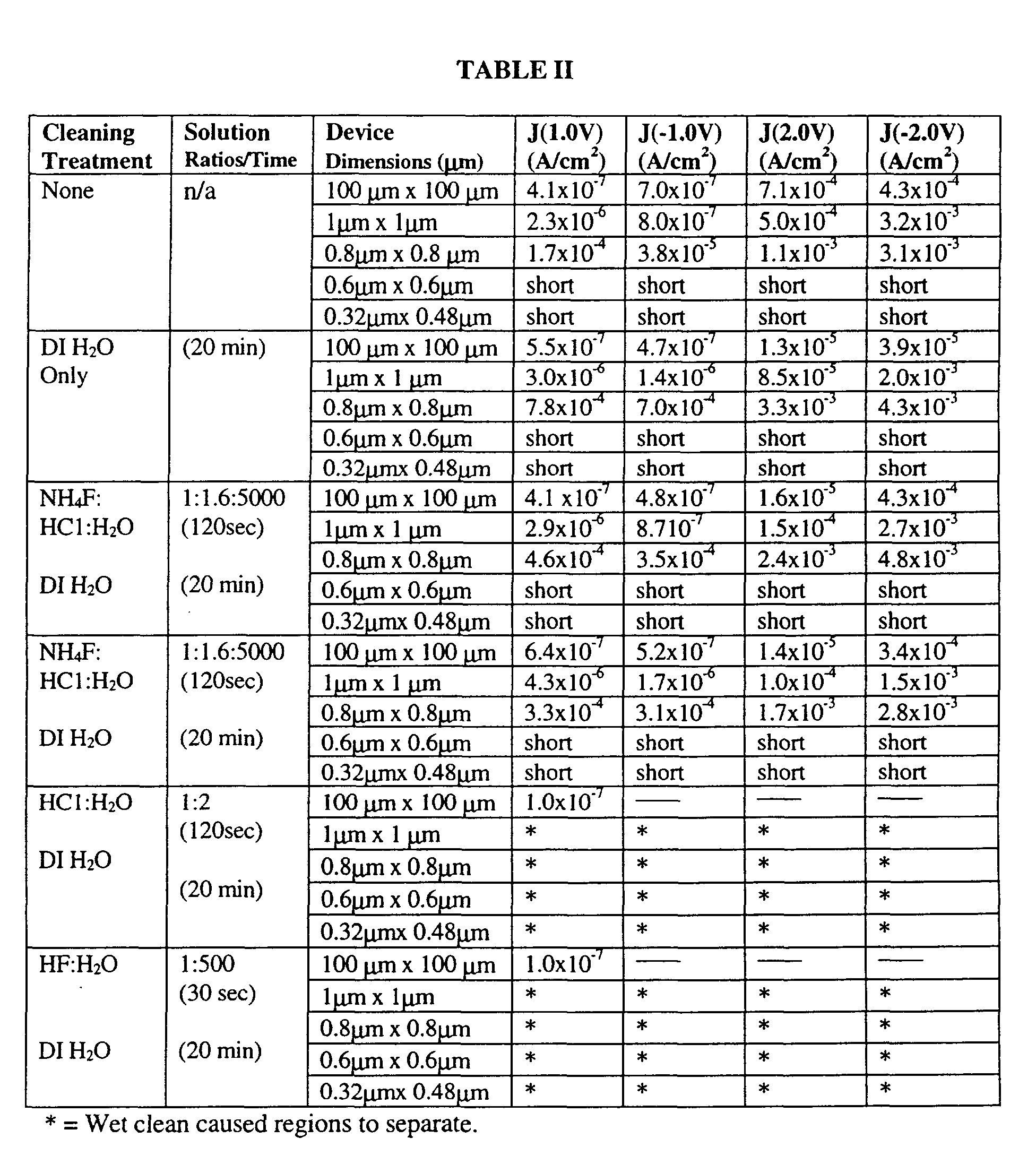
- each stack was subjected to a rapid thermal anneal at 600° C in N 2 for 10 minutes.
- Leakage current, J was measured using top electrodes with several geometries, however the top electrode area was maintained at a constant 1.4 x 10 -4 cm 2 or 3.2 x 10 -4 cm 2 depending upon the stack geometry. The results of these experiments are contained in Table II.
- the leakage current J for fluorine compound/chlorine compound etchants was less than that for the HF etchant and HCl etchants.
- the fluorine compound/chlorine compound etchants did not cause separation of the stack regions as occurred with the HF and HCl etchants (indicated with an asterisk). This separation resulted from the HF and HCl etchants aggressively etching the capacitor stacks at the intersections of the ferroelectric region and the top and/or bottom electrodes. Accordingly, the fluorine compound/chlorine compound etchants of the present invention effectively remove the damaged region formed on FeRAM capacitor stacks with current leakage results superior to those obtained with conventional etchants.
Abstract
Description
| Etch Chemistry | Proportion of Constituents by Vol. | PZT Etch Rate (nm/sec) | SiO2 Etch Rate (nm/sec) | TiAIN Etch Rate (nm/sec) |
| NH4F:HCl:H2O | 1:1.6:20 | >70 | 0.1 | 0 |
| NH4F:HCl:H2O | 1:1.6:100 | 6 | 0 | 0 |
| NH4F:HCl:H2O | 1:1.6:1000 | 2.5 | 0 | 0 |
| NH4F:HCl:H2O | 1:1.6:5000 | 0.1 | 0 | 0 |
| HF:HCl:H2O | 1:1.6:100 | 27.1 | 0 | 0 |
| HF:HCl:H2O | 1:1.6:1000 | 3.3 | 0 | 0 |
| HF:H2O | 1:10 | 8.4 | 0 | 0 |
| HF:H2O | 1:100 | 1.0 | 0.04 | 0 |
| HF:H2O | 1:500 | 0.6 | 0 | 0 |
| HCl:H2O | 1:1 | 2.9 | 0 | 0 |
| HCl:H2O | 1:2 | 0.08 | 0 | 0 |
| HCl:H2O | 1:4 | ∼0 | 0 | 0 |
Claims (10)
- A post-etch cleaning process (20) for a semiconductor device, comprising:providing an etchant comprising both a fluorine compound and a chlorine compound; andapplying the etchant to the semiconductor device in a wet cleaning process.
- The process of claim 1, wherein the fluorine compound is selected from the group consisting of NH4F, NaF, CaF2, and HF.
- The process of claim 1, wherein the chlorine compound is selected from the group consisting of NH4Cl, HCI, NaCl, and NaClO4.
- The process of claim 1, wherein the fluorine compound comprises NH4F.
- The process of claim 1, wherein the fluorine compound comprises HF.
- The process of claim 1, wherein the chlorine compound comprises HCl.
- The process of claim 5, wherein the etchant has a fluorine compound:chlorine compound:water ratio ranging from approximately 1:1.6:5000 to 1:1.6:1000.
- The process of claim 1, wherein the wet cleaning process comprises a bath immersion process.
- The process of claim 1, wherein the wet cleaning process comprises a spray process.
- The process of claim 1, wherein the wet cleaning process comprises a spin rinse dry process.
Priority Applications (2)
| Application Number | Priority Date | Filing Date | Title |
|---|---|---|---|
| EP04012770A EP1453085B1 (en) | 2000-08-31 | 2001-08-07 | Post-etch cleaning treatment |
| EP04012769A EP1453084B1 (en) | 2000-08-31 | 2001-08-07 | Post-etch cleaning treatment |
Applications Claiming Priority (2)
| Application Number | Priority Date | Filing Date | Title |
|---|---|---|---|
| US650224 | 2000-08-31 | ||
| US09/650,224 US6692976B1 (en) | 2000-08-31 | 2000-08-31 | Post-etch cleaning treatment |
Related Child Applications (1)
| Application Number | Title | Priority Date | Filing Date |
|---|---|---|---|
| EP04012769A Division EP1453084B1 (en) | 2000-08-31 | 2001-08-07 | Post-etch cleaning treatment |
Publications (3)
| Publication Number | Publication Date |
|---|---|
| EP1195803A2 true EP1195803A2 (en) | 2002-04-10 |
| EP1195803A3 EP1195803A3 (en) | 2003-12-10 |
| EP1195803B1 EP1195803B1 (en) | 2006-11-15 |
Family
ID=24608004
Family Applications (3)
| Application Number | Title | Priority Date | Filing Date |
|---|---|---|---|
| EP04012770A Expired - Lifetime EP1453085B1 (en) | 2000-08-31 | 2001-08-07 | Post-etch cleaning treatment |
| EP04012769A Expired - Lifetime EP1453084B1 (en) | 2000-08-31 | 2001-08-07 | Post-etch cleaning treatment |
| EP01119044A Expired - Lifetime EP1195803B1 (en) | 2000-08-31 | 2001-08-07 | Post-etch cleaning treatment |
Family Applications Before (2)
| Application Number | Title | Priority Date | Filing Date |
|---|---|---|---|
| EP04012770A Expired - Lifetime EP1453085B1 (en) | 2000-08-31 | 2001-08-07 | Post-etch cleaning treatment |
| EP04012769A Expired - Lifetime EP1453084B1 (en) | 2000-08-31 | 2001-08-07 | Post-etch cleaning treatment |
Country Status (4)
| Country | Link |
|---|---|
| US (1) | US6692976B1 (en) |
| EP (3) | EP1453085B1 (en) |
| JP (1) | JP4898030B2 (en) |
| DE (3) | DE60143229D1 (en) |
Cited By (2)
| Publication number | Priority date | Publication date | Assignee | Title |
|---|---|---|---|---|
| EP1995781A2 (en) * | 2002-12-20 | 2008-11-26 | Infineon Technologies AG | Method for manufacturing a condenser device and condenser device |
| JP2010147088A (en) * | 2008-12-16 | 2010-07-01 | Tdk Corp | Method of manufacturing piezoelectric element |
Families Citing this family (16)
| Publication number | Priority date | Publication date | Assignee | Title |
|---|---|---|---|---|
| EP1511074B1 (en) * | 2003-08-01 | 2015-01-28 | Imec | A method for selective removal of high-K material |
| TWI385720B (en) * | 2004-03-24 | 2013-02-11 | Tosoh Corp | Etching composition and etching treatment method |
| CN100352013C (en) * | 2004-07-16 | 2007-11-28 | 鸿富锦精密工业(深圳)有限公司 | Dry etch post process method |
| EP1648024A1 (en) * | 2004-10-15 | 2006-04-19 | Sez Ag | Method for removing particles from a surface |
| US7220600B2 (en) * | 2004-12-17 | 2007-05-22 | Texas Instruments Incorporated | Ferroelectric capacitor stack etch cleaning methods |
| US20090061632A1 (en) * | 2007-08-28 | 2009-03-05 | Texas Instruments Incorporated | Methods for cleaning etch residue deposited by wet etch processes for high-k dielectrics |
| JP4998337B2 (en) * | 2008-03-11 | 2012-08-15 | Tdk株式会社 | Dielectric element manufacturing method |
| US8318606B2 (en) * | 2009-08-25 | 2012-11-27 | Lsi Corporation | Dielectric etching |
| JP2012056194A (en) * | 2010-09-09 | 2012-03-22 | Seiko Epson Corp | Piezoelectric element, piezoelectric actuator, liquid ejecting head, and liquid ejecting apparatus |
| JP2013102089A (en) * | 2011-11-09 | 2013-05-23 | Adeka Corp | Etchant composition for lead titanate-based material |
| US8613863B2 (en) * | 2011-11-29 | 2013-12-24 | Intermolecular, Inc. | Methods for selective etching of a multi-layer substrate |
| JP6353636B2 (en) * | 2013-06-21 | 2018-07-04 | 東京エレクトロン株式会社 | Method and apparatus for removing titanium oxide film |
| US10714159B2 (en) | 2018-05-09 | 2020-07-14 | Micron Technology, Inc. | Indication in memory system or sub-system of latency associated with performing an access command |
| US11010092B2 (en) * | 2018-05-09 | 2021-05-18 | Micron Technology, Inc. | Prefetch signaling in memory system or sub-system |
| US10754578B2 (en) | 2018-05-09 | 2020-08-25 | Micron Technology, Inc. | Memory buffer management and bypass |
| US10942854B2 (en) | 2018-05-09 | 2021-03-09 | Micron Technology, Inc. | Prefetch management for memory |
Citations (8)
| Publication number | Priority date | Publication date | Assignee | Title |
|---|---|---|---|---|
| US4759823A (en) * | 1987-06-02 | 1988-07-26 | Krysalis Corporation | Method for patterning PLZT thin films |
| US5258093A (en) * | 1992-12-21 | 1993-11-02 | Motorola, Inc. | Procss for fabricating a ferroelectric capacitor in a semiconductor device |
| US5337207A (en) * | 1992-12-21 | 1994-08-09 | Motorola | High-permittivity dielectric capacitor for use in a semiconductor device and process for making the same |
| JPH1012836A (en) * | 1996-06-18 | 1998-01-16 | Matsushita Electron Corp | Method for manufacturing capacitance element |
| EP0827188A2 (en) * | 1996-08-09 | 1998-03-04 | Mitsubishi Gas Chemical Company, Inc. | Cleaning liquid for producing semiconductor device and process for producing semiconductor device using same |
| EP0918081A1 (en) * | 1997-11-21 | 1999-05-26 | International Business Machines Corporation | Etching composition and use |
| EP0968979A1 (en) * | 1998-06-30 | 2000-01-05 | Siemens Aktiengesellschaft | Etching of Bi-based metal oxides ceramics |
| WO2001001474A1 (en) * | 1999-06-29 | 2001-01-04 | Micron Technology, Inc. | Acid blend for removing etch residue on semiconductor substrates |
Family Cites Families (19)
| Publication number | Priority date | Publication date | Assignee | Title |
|---|---|---|---|---|
| US3099609A (en) * | 1961-09-11 | 1963-07-30 | Katayose Kimiyoshi | Method of electroplating aluminum or its alloy with porous hard chromium |
| US4040897A (en) * | 1975-05-05 | 1977-08-09 | Signetics Corporation | Etchants for glass films on metal substrates |
| JPS5741365A (en) * | 1980-08-22 | 1982-03-08 | Ishikawajima Harima Heavy Ind Co Ltd | Aluminizing method for iron and steel |
| US4496612A (en) * | 1982-04-06 | 1985-01-29 | E. I. Du Pont De Nemours And Company | Aqueous flux for hot dip metalizing process |
| JPS6064437A (en) * | 1983-09-20 | 1985-04-13 | Toshiba Corp | Etching liquid for lead group passivation glass |
| JPH06163496A (en) * | 1992-11-24 | 1994-06-10 | Mitsubishi Materials Corp | Liquid for cleaning silicon wafer, and cleaning method |
| BR9304546A (en) * | 1993-11-19 | 1995-08-01 | Brasilia Telecom | Process for chemical deposition followed by electrolytic deposition of metals on alumina |
| US5681398A (en) * | 1995-03-17 | 1997-10-28 | Purex Co., Ltd. | Silicone wafer cleaning method |
| WO1996041628A1 (en) * | 1995-06-12 | 1996-12-27 | Ono Pharmaceutical Co., Ltd. | Granules containing pranlukast, process for producing the granules, and method of lowering cohesiveness of pranlukast |
| US6153484A (en) * | 1995-06-19 | 2000-11-28 | Imec Vzw | Etching process of CoSi2 layers |
| JP3274389B2 (en) * | 1996-08-12 | 2002-04-15 | 株式会社東芝 | Semiconductor substrate cleaning method |
| US5826773A (en) * | 1997-01-31 | 1998-10-27 | Straemke; Siegfried | Rope material transfer structure |
| JP3337622B2 (en) * | 1997-07-16 | 2002-10-21 | 松下電器産業株式会社 | Selective etchant and method of manufacturing semiconductor device using the etchant |
| US5989948A (en) * | 1997-09-22 | 1999-11-23 | Vlsi Technology, Inc. | Methods of forming pairs of transistors, and methods of forming pairs of transistors having different voltage tolerances |
| FR2769248B1 (en) * | 1997-10-06 | 2000-01-28 | St Microelectronics Sa | PROCESS FOR MECHANICAL-CHEMICAL POST-POLISHING CLEANING OF AN OXIDE OR NITRIDE LAYER DEPOSITED ON A SUBSTRATE |
| US6294027B1 (en) * | 1997-10-21 | 2001-09-25 | Lam Research Corporation | Methods and apparatus for cleaning semiconductor substrates after polishing of copper film |
| JP3185732B2 (en) * | 1997-11-20 | 2001-07-11 | 日本電気株式会社 | Substrate surface metal contamination removal method |
| US6346505B1 (en) * | 1998-01-16 | 2002-02-12 | Kurita Water Industries, Ltd. | Cleaning solution for electromaterials and method for using same |
| US6127282A (en) * | 1998-11-12 | 2000-10-03 | Advanced Micro Devices, Inc. | Method for removing copper residue from surfaces of a semiconductor wafer |
-
2000
- 2000-08-31 US US09/650,224 patent/US6692976B1/en not_active Expired - Lifetime
-
2001
- 2001-08-07 DE DE60143229T patent/DE60143229D1/en not_active Expired - Lifetime
- 2001-08-07 DE DE60143228T patent/DE60143228D1/en not_active Expired - Lifetime
- 2001-08-07 EP EP04012770A patent/EP1453085B1/en not_active Expired - Lifetime
- 2001-08-07 DE DE60124487T patent/DE60124487T2/en not_active Expired - Lifetime
- 2001-08-07 EP EP04012769A patent/EP1453084B1/en not_active Expired - Lifetime
- 2001-08-07 EP EP01119044A patent/EP1195803B1/en not_active Expired - Lifetime
- 2001-08-21 JP JP2001250341A patent/JP4898030B2/en not_active Expired - Fee Related
Patent Citations (9)
| Publication number | Priority date | Publication date | Assignee | Title |
|---|---|---|---|---|
| US4759823A (en) * | 1987-06-02 | 1988-07-26 | Krysalis Corporation | Method for patterning PLZT thin films |
| US5258093A (en) * | 1992-12-21 | 1993-11-02 | Motorola, Inc. | Procss for fabricating a ferroelectric capacitor in a semiconductor device |
| US5337207A (en) * | 1992-12-21 | 1994-08-09 | Motorola | High-permittivity dielectric capacitor for use in a semiconductor device and process for making the same |
| JPH1012836A (en) * | 1996-06-18 | 1998-01-16 | Matsushita Electron Corp | Method for manufacturing capacitance element |
| US6100100A (en) * | 1996-06-18 | 2000-08-08 | Matsushita Electronics Corporation | Method for manufacturing capacitor element |
| EP0827188A2 (en) * | 1996-08-09 | 1998-03-04 | Mitsubishi Gas Chemical Company, Inc. | Cleaning liquid for producing semiconductor device and process for producing semiconductor device using same |
| EP0918081A1 (en) * | 1997-11-21 | 1999-05-26 | International Business Machines Corporation | Etching composition and use |
| EP0968979A1 (en) * | 1998-06-30 | 2000-01-05 | Siemens Aktiengesellschaft | Etching of Bi-based metal oxides ceramics |
| WO2001001474A1 (en) * | 1999-06-29 | 2001-01-04 | Micron Technology, Inc. | Acid blend for removing etch residue on semiconductor substrates |
Non-Patent Citations (1)
| Title |
|---|
| PATENT ABSTRACTS OF JAPAN vol. 1998, no. 05 30 April 1998 -& JP 10 012 836 A (MATSUSHITA ELECTRON CORP) 16 January 1998 * |
Cited By (2)
| Publication number | Priority date | Publication date | Assignee | Title |
|---|---|---|---|---|
| EP1995781A2 (en) * | 2002-12-20 | 2008-11-26 | Infineon Technologies AG | Method for manufacturing a condenser device and condenser device |
| JP2010147088A (en) * | 2008-12-16 | 2010-07-01 | Tdk Corp | Method of manufacturing piezoelectric element |
Also Published As
| Publication number | Publication date |
|---|---|
| US6692976B1 (en) | 2004-02-17 |
| EP1195803B1 (en) | 2006-11-15 |
| EP1453084A3 (en) | 2004-09-15 |
| DE60143228D1 (en) | 2010-11-18 |
| EP1453084B1 (en) | 2010-10-06 |
| EP1453085A3 (en) | 2004-09-15 |
| JP2002151484A (en) | 2002-05-24 |
| DE60124487D1 (en) | 2006-12-28 |
| EP1453085A2 (en) | 2004-09-01 |
| EP1195803A3 (en) | 2003-12-10 |
| DE60143229D1 (en) | 2010-11-18 |
| JP4898030B2 (en) | 2012-03-14 |
| EP1453084A2 (en) | 2004-09-01 |
| EP1453085B1 (en) | 2010-10-06 |
| DE60124487T2 (en) | 2007-03-01 |
Similar Documents
| Publication | Publication Date | Title |
|---|---|---|
| US6692976B1 (en) | Post-etch cleaning treatment | |
| US6245650B1 (en) | Process for production of semiconductor device | |
| US6162738A (en) | Cleaning compositions for high dielectric structures and methods of using same | |
| JP3189892B2 (en) | Semiconductor substrate cleaning method and cleaning liquid | |
| JP3645144B2 (en) | Manufacturing method of semiconductor device | |
| JP4010819B2 (en) | Manufacturing method of semiconductor device | |
| US7135413B2 (en) | Cleaning solution for removing damaged portion of ferroelectric layer and cleaning method using the same | |
| US6454956B1 (en) | Structuring method | |
| US6524868B2 (en) | Method for fabricating semiconductor memory device | |
| JP3166746B2 (en) | Capacitor and method of manufacturing the same | |
| JP2002164514A (en) | Method for manufacturing semiconductor device | |
| JP3159257B2 (en) | Method for manufacturing semiconductor device | |
| JP2000133643A (en) | Cleaning method of pzt-based thin film using etching liquid | |
| US7228865B2 (en) | FRAM capacitor stack clean | |
| JP4054887B2 (en) | Ruthenium silicide wet etching method and etchant | |
| US7015049B2 (en) | Fence-free etching of iridium barrier having a steep taper angle | |
| US7041511B2 (en) | Pt/PGO etching process for FeRAM applications | |
| US7888139B2 (en) | Fabricating method of nonvolatile semiconductor storage apparatus | |
| JP3173598B2 (en) | Method and apparatus for cleaning semiconductor substrate | |
| JP2000223464A (en) | Board cleaning method | |
| KR100582351B1 (en) | Method for fabricating capacitor in semiconductor device | |
| JP2003100715A (en) | Semiconductor cleaning agent |
Legal Events
| Date | Code | Title | Description |
|---|---|---|---|
| PUAI | Public reference made under article 153(3) epc to a published international application that has entered the european phase |
Free format text: ORIGINAL CODE: 0009012 |
|
| AK | Designated contracting states |
Kind code of ref document: A2 Designated state(s): AT BE CH CY DE DK ES FI FR GB GR IE IT LI LU MC NL PT SE TR |
|
| AX | Request for extension of the european patent |
Free format text: AL;LT;LV;MK;RO;SI |
|
| RAP1 | Party data changed (applicant data changed or rights of an application transferred) |
Owner name: AGILENT TECHNOLOGIES, INC. (A DELAWARE CORPORATION |
|
| PUAL | Search report despatched |
Free format text: ORIGINAL CODE: 0009013 |
|
| AK | Designated contracting states |
Kind code of ref document: A3 Designated state(s): AT BE CH CY DE DK ES FI FR GB GR IE IT LI LU MC NL PT SE TR |
|
| AX | Request for extension of the european patent |
Extension state: AL LT LV MK RO SI |
|
| 17P | Request for examination filed |
Effective date: 20040528 |
|
| AKX | Designation fees paid |
Designated state(s): DE FR GB |
|
| 17Q | First examination report despatched |
Effective date: 20040805 |
|
| GRAP | Despatch of communication of intention to grant a patent |
Free format text: ORIGINAL CODE: EPIDOSNIGR1 |
|
| GRAS | Grant fee paid |
Free format text: ORIGINAL CODE: EPIDOSNIGR3 |
|
| GRAA | (expected) grant |
Free format text: ORIGINAL CODE: 0009210 |
|
| AK | Designated contracting states |
Kind code of ref document: B1 Designated state(s): DE FR GB |
|
| REG | Reference to a national code |
Ref country code: GB Ref legal event code: FG4D |
|
| RAP2 | Party data changed (patent owner data changed or rights of a patent transferred) |
Owner name: AVAGO TECHNOLOGIES GENERAL IP (SINGAPORE) PTE. LTD |
|
| REF | Corresponds to: |
Ref document number: 60124487 Country of ref document: DE Date of ref document: 20061228 Kind code of ref document: P |
|
| ET | Fr: translation filed | ||
| PLBE | No opposition filed within time limit |
Free format text: ORIGINAL CODE: 0009261 |
|
| STAA | Information on the status of an ep patent application or granted ep patent |
Free format text: STATUS: NO OPPOSITION FILED WITHIN TIME LIMIT |
|
| 26N | No opposition filed |
Effective date: 20070817 |
|
| REG | Reference to a national code |
Ref country code: FR Ref legal event code: ST Effective date: 20080430 |
|
| PG25 | Lapsed in a contracting state [announced via postgrant information from national office to epo] |
Ref country code: FR Free format text: LAPSE BECAUSE OF NON-PAYMENT OF DUE FEES Effective date: 20070831 |
|
| PGFP | Annual fee paid to national office [announced via postgrant information from national office to epo] |
Ref country code: DE Payment date: 20110803 Year of fee payment: 11 Ref country code: GB Payment date: 20110803 Year of fee payment: 11 |
|
| GBPC | Gb: european patent ceased through non-payment of renewal fee |
Effective date: 20120807 |
|
| PG25 | Lapsed in a contracting state [announced via postgrant information from national office to epo] |
Ref country code: DE Free format text: LAPSE BECAUSE OF NON-PAYMENT OF DUE FEES Effective date: 20130301 Ref country code: GB Free format text: LAPSE BECAUSE OF NON-PAYMENT OF DUE FEES Effective date: 20120807 |
|
| REG | Reference to a national code |
Ref country code: DE Ref legal event code: R119 Ref document number: 60124487 Country of ref document: DE Effective date: 20130301 |