Technical Field of the Invention
The invention relates to a portable radio communications
device having a display on which a position indicator can
be positioned, and means for controlling the position of
the position indicator on the display manually by a user.
Description of Related Art
Modern portable radio communications devices, such as
e.g. mobile telephones, are increasingly used for the
presentation of information to a user on a display. This
information can be e.g. call information, received messages,
messages to be sent from the device or information
downloaded from a network, such as the internet. In many
of these situations it is necessary or convenient to be
able to control the position of a position indicator,
such as a pointer or cursor, on the display.
Several solutions to the control of a cursor on the display
of a portable communications device are known. Very
common is a set of arrow keys, typically two up/down keys
and two left/right keys arranged e.g. in a diamond configuration.
Pressing one of the keys effects the movement
of the cursor a step in a direction corresponding to the
key. However this solution is relatively time consuming
when the cursor has to be moved a longer distance on the
display. Further, the four keys must have a sufficiently
large size and thus they occupy a considerable area on
the communications device, and this is incompatible with
the increasing demand for smaller and smaller devices.
Another solution is to use a joystick as shown in e.g. JP
8-307 495. This allows a faster movement of the cursor,
but since the joystick necessarily has to be mounted so
that it extends from the surface of the communications
device, it will very easily stick to the clothing e.g.
when the device is taken out of a pocket. This means that
the user may loose the grip of the device or that the
joystick itself may break off.
A further solution is disclosed in EP 463 856 which suggests
the use of a thumb wheel or a thumb ball for scanning
menus on the display of a mobile telephone. Also
this solution takes up a considerable area on the device.
All these solutions include mechanical components which
will always be subjected to some sort of mechanical wear
resulting in reliability problems. Another problem is
that dirt and moisture can enter into the mechanical components
and thus accelerate the wear and disturb the contact
surfaces. This problem is of particular importance
with the portable communications devices, because they
are often kept in dirty and damp pockets for long periods
of time or even used in rainy weather. The mechanical solutions
also have the disadvantage that in order to operate
them, the user has to press with a finger on the
keys, the joystick or the thumb ball. This pressure creates
mechanical forces which are easily transported to
printed circuit boards inside the device where they could
cause soldered connections to be broken.
Therefore, it is an object of the invention to provide a
portable radio communications device of the above-mentioned
type which is more suitable to use in the
above-mentioned environments for portable communications
devices, which means that the solution should not be sensitive
to dirt and moisture, and the operation of the device
should not require that fingers are pressed against
the device.
Summary
According to the invention the object is achieved in that
the controlling means comprise an optical emitter adapted
to illuminate an external object through a translucent
and moisture-proof surface; an optical detector adapted
to detect changes in light reflected from said external
object due to the movement thereof; and circuitry for
generating a control signal for the position of said position
indicator in dependence on said changes in reflected
light.
The use of optical detection of the movement of an object,
such as a finger, through a translucent and moisture-proof
surface of the portable radio communications
device provides a very easily operated control device.
The finger is just moved across the device, and there is
no need to press the finger against the device. In this
way forces on the printed circuit boards are avoided. The
moisture-proof surface ensures that the device is not
sensitive to dirt and moisture.
The use of optical control of a cursor on a display is
known in relation to computers, e.g. from US 5 801 681
and EP 942 285, but although these devices avoid the use
of mechanical moving parts, the use on portable communications
devices, such as mobile telephones, is not suggested,
and there is no indication that the devices
should be able to solve the dirt and moisture problem,
which is unavoidable for portable communications devices
but not relevant to computers. Further, the optical control
of the cursor on a display allows a user to operate
the portable communications device with gloves, which is
very advantageous in relation to portable communications
devices, because they are often used outside in the winter
time, but which is hardly relevant to computers.
In expedient embodiments the communications device is a
mobile telephone, and the position indicator can be a
cursor.
When the optical emitter emits infrared light, it is ensured
that the emitted light is not visible from the outside
of the device. This embodiment is often preferred,
because users are interested in a function and not in how
such a function is implemented.
Alternatively, when the optical emitter emits visible
light, a high-tech look that could be attractive to especially
young people is provided.
When the circuitry for generating a control signal is
further adapted to generate a selection signal for selecting
an item indicated on said display by the position
of said position indicator, the control means can also be
used to activate e.g. a function which has been indicated
by moving the position indicator to a corresponding item
on the display. This is similar to the use of a mouse
button on a normal computer mouse, but the selection can
be performed without the addition of a separate button.
The activation can take place by e.g. removing the external
object from the controlling means or by placing the
object thereon for only a short time. In this way all the
keys or buttons, or at least most of them, on a portable
communications device can be replaced by showing the keys
on the display and then selecting one of them with the
controlling means of the invention.
When the controlling means are arranged in a surface of
the device adjacent to said display, a solution which is
very easily operated is achieved, because the user is
able to look at the control device and the display with
the cursor simultaneously.
Brief Description of the Drawings
The invention will now be described more fully below with
reference to the drawings, in which
Detailed Description of Embodiments
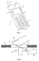
Figure 1 shows an example of a portable radio communications
device, in this case a mobile telephone 1, in which
the invention can be used. The telephone has an antenna
2, a loudspeaker 3, a microphone 4 and a number of keys
5. The keys 5 are used for entering telephone numbers,
messages, etc. A display 6 is provided for presentation
of information to the user of the telephone. This information
could be numbers or messages entered by means of
the keys 5, or it could be information received by the
device through the antenna 2. An example of such information
could be a menu from which the user can select a
specific item, which is done by moving a cursor or
pointer 7 around on the display 6.
The movement of the cursor 7 is controlled by the cursor
control device 8 according to the invention. This device
8 is an optical control device which will be described in
more detail below. The optical control device includes a
translucent window integrated into the surface of the
telephone 1. The position of the cursor 7 is controlled
by moving e.g. a finger on the window of the device 8.
The optical control device 8 may be implemented in several
different ways, the construction of which is known
per se. One implementation is described below and illustrated
in figure 2.
Figure 2 shows the front cover 11 of the mobile telephone
1 and a translucent window 12 arranged in the front
cover. The window 12 can be made of any translucent material
such as glass or a plastics material, and it is
mounted in the front cover in such a way that water,
moisture or dust is prevented from entering into the device.
The area of the window 12 corresponds to the outline
of the control device 8 as shown in figure 1. A
light source 13 is placed behind the window 12. The light
source 13 will typically be a light emitting diode (LED)
or a laser diode, but also other types of light sources
are possible. A detector 14 sensitive to the light emitted
from the light source 13 is also located behind the
window 12, and a shield 15 prevents the light from the
light source 13 from being transmitted directly to the
detector 14. Alternatively, the light source 13 may be of
a directional type so that no light is emitted in the direction
of the detector 14.
In a preferred embodiment the light source 13 emits light
in a relatively narrow wavelength band only, and the detector
14 has a good sensitivity for light in this wavelength
band while the sensitivity for light outside this
band is lower. This means that in a situation where no
objects are located in front of the window 12 the detector
14 will not detect any light from the light source
13, and it will not be disturbed by ambient light outside
the band through the window 12. If, however, an object,
such as a finger 16 of a user, is placed in front of the
window 12, the light from the light source 13 will be reflected
and diffused by the finger, as shown in the figure,
and some of the reflected and diffused light will
have a direction towards the detector 14. A lens 17 focuses
this light such that an image of the contact area
between the finger 16 and the window 12 is created on the
detector 14.
In order to detect the location of the finger 16 on the
window 12 the detector 14 can be divided into four segments
21, 22, 23 and 24, as shown in figure 3, which
shows the situation before the finger 16 is placed on the
window 12, i.e. when no light from the light source 13 is
received by the detector 14. Each of these segments of
the detector 14 is adapted to provide an electrical output
signal proportional to, or at least dependent on, the
amount of light received by the segment. These signals
are received by a control circuit 18.
Figure 4 shows the detector 14 when a finger 16 is placed
on the window 12 and an image 25 of the contact area between
the finger and the window surface is created on the
detector 14 by the light reflected from the finger. As
will be seen, the image 25 is located mainly in the lower
part of the detector so that the two segments 23 and 24
receive more light than the segments 21 and 22. Consequently,
the segments 23 and 24 also produce higher output
signals than the segments 21 and 22. This could be a
situation where the finger 16 is placed on the right side
of the window 12 in figure 2.
If the finger 16 is moved to the left in figure 2, the
image 25 in figure 4 will move correspondingly in the upward
direction on the detector 14. This means that the
amount of light received by the segments 23 and 24 decreases
while that received by the segments 21 and 22 increases
correspondingly. A similar change will occur in
the output signals from the segments, and the control
circuit 18 will detect the change and convert it to a
control signal that can be used directly to control the
movement of the cursor 7 on the display 6 in an upward
direction, i.e. in a direction towards the antenna 2 in
figure 1. Figure 5 shows the image 26 of the contact area
after the finger has been moved, as described.
If the finger 16 was instead moved in a direction into
the paper in figure 2, the image 25 in figure 4 would
move to the right, and the amount of light received by
the segments 22 and 23 would decrease while that received
by the segments 21 and 24 would increase correspondingly.
This would also be the case for the corresponding output
signals, and the control signal generated by the control
circuit 18 would move the cursor 7 to the right on the
display 6.
Thus the movement of a finger 16 on the surface of the
window 12 results in the generation of a control signal
which is used to move the cursor 7 corresponding to the
movement of the finger. This gives an easy and direct way
of controlling the movement of the cursor on the display
of the mobile telephone, and at the same time the moisture-proof
window 12 ensures that moisture and dirt cannot
enter into the device.
When the cursor 7 has been moved to a certain position on
the display indicating a specific item corresponding to
e.g. a specific function of the telephone, this item can
be selected by using a separate selection button. This
button can be a normal mechanical button, or it can be a
separate window of the same type like the window 12 where
the movement of a finger activates the item indicated by
the cursor 7. Alternatively, the selection can also be
done by movement of the finger on the window 12 itself.
As an example, this can be done by placing the finger on
the window and then removing it again after a short time,
or the finger can simply be removed from the window very
fast after the cursor has been moved to the desired location.
In this way all the keys or buttons, or at least most of
them, on a mobile telephone can be replaced by showing
the keys on the display and then selecting one of them by
first moving the cursor to the right position by means of
the finger placed on the window and then selecting the
indicated key.
To avoid the risk of unintentional operation of the cursor
control device 8 due to the movement of clothing in
relation to the window 12 when the mobile telephone is
stored in e.g. a pocket, the control circuit 18 can be
arranged to be active only when the telephone itself is
in an active mode. Alternatively, a separate button can
be used to switch the cursor control device 8 on and off,
so that the user can activate the device when it is
needed and then deactivate it again after the use.
The light source 13 can be of an infrared type, which ensures
that the emitted light is not visible from the outside
of the window 12. This embodiment is normally preferred,
because users are interested in a function and
not in how such a function is implemented. On the other
hand, an embodiment using light in the visible band will
provide the communications device with a high-tech look
that could be attractive to especially young people.
In the embodiment described above, the window 12 has a
size which is larger than the contact area between the
finger 16 and the window. However, it should be noted
that in a practical embodiment a much smaller window
would be sufficient. The detector 14 does not need the
complete image of the contact area in order to detect the
movement thereof. In this case, a detector having more
than four segments can be advantageous. As an example, a
detector of the type which is normally used as sensors in
TV cameras can be used.
Also a detector using coherent detection of the light reflected
from the finger and utilizing reference light
transmitted directly from the light source to detect the
movement of the finger can be used.
Although a preferred embodiment of the present invention
has been described and shown, the invention is not restricted
to it, but may also be embodied in other ways
within the scope of the subject-matter defined in the
following claims.