EP1205583B1 - Manufacturing method for producing silicon carbide crystal using source gases and apparatus for the same - Google Patents
Manufacturing method for producing silicon carbide crystal using source gases and apparatus for the same Download PDFInfo
- Publication number
- EP1205583B1 EP1205583B1 EP01126619A EP01126619A EP1205583B1 EP 1205583 B1 EP1205583 B1 EP 1205583B1 EP 01126619 A EP01126619 A EP 01126619A EP 01126619 A EP01126619 A EP 01126619A EP 1205583 B1 EP1205583 B1 EP 1205583B1
- Authority
- EP
- European Patent Office
- Prior art keywords
- crucible
- inlet conduit
- silicon carbide
- carbide single
- single crystals
- Prior art date
- Legal status (The legal status is an assumption and is not a legal conclusion. Google has not performed a legal analysis and makes no representation as to the accuracy of the status listed.)
- Expired - Lifetime
Links
Images

Classifications
-
- C—CHEMISTRY; METALLURGY
- C30—CRYSTAL GROWTH
- C30B—SINGLE-CRYSTAL GROWTH; UNIDIRECTIONAL SOLIDIFICATION OF EUTECTIC MATERIAL OR UNIDIRECTIONAL DEMIXING OF EUTECTOID MATERIAL; REFINING BY ZONE-MELTING OF MATERIAL; PRODUCTION OF A HOMOGENEOUS POLYCRYSTALLINE MATERIAL WITH DEFINED STRUCTURE; SINGLE CRYSTALS OR HOMOGENEOUS POLYCRYSTALLINE MATERIAL WITH DEFINED STRUCTURE; AFTER-TREATMENT OF SINGLE CRYSTALS OR A HOMOGENEOUS POLYCRYSTALLINE MATERIAL WITH DEFINED STRUCTURE; APPARATUS THEREFOR
- C30B25/00—Single-crystal growth by chemical reaction of reactive gases, e.g. chemical vapour-deposition growth
-
- C—CHEMISTRY; METALLURGY
- C30—CRYSTAL GROWTH
- C30B—SINGLE-CRYSTAL GROWTH; UNIDIRECTIONAL SOLIDIFICATION OF EUTECTIC MATERIAL OR UNIDIRECTIONAL DEMIXING OF EUTECTOID MATERIAL; REFINING BY ZONE-MELTING OF MATERIAL; PRODUCTION OF A HOMOGENEOUS POLYCRYSTALLINE MATERIAL WITH DEFINED STRUCTURE; SINGLE CRYSTALS OR HOMOGENEOUS POLYCRYSTALLINE MATERIAL WITH DEFINED STRUCTURE; AFTER-TREATMENT OF SINGLE CRYSTALS OR A HOMOGENEOUS POLYCRYSTALLINE MATERIAL WITH DEFINED STRUCTURE; APPARATUS THEREFOR
- C30B29/00—Single crystals or homogeneous polycrystalline material with defined structure characterised by the material or by their shape
- C30B29/10—Inorganic compounds or compositions
- C30B29/36—Carbides
-
- Y—GENERAL TAGGING OF NEW TECHNOLOGICAL DEVELOPMENTS; GENERAL TAGGING OF CROSS-SECTIONAL TECHNOLOGIES SPANNING OVER SEVERAL SECTIONS OF THE IPC; TECHNICAL SUBJECTS COVERED BY FORMER USPC CROSS-REFERENCE ART COLLECTIONS [XRACs] AND DIGESTS
- Y10—TECHNICAL SUBJECTS COVERED BY FORMER USPC
- Y10S—TECHNICAL SUBJECTS COVERED BY FORMER USPC CROSS-REFERENCE ART COLLECTIONS [XRACs] AND DIGESTS
- Y10S117/00—Single-crystal, oriented-crystal, and epitaxy growth processes; non-coating apparatus therefor
- Y10S117/90—Apparatus characterized by composition or treatment thereof, e.g. surface finish, surface coating
-
- Y—GENERAL TAGGING OF NEW TECHNOLOGICAL DEVELOPMENTS; GENERAL TAGGING OF CROSS-SECTIONAL TECHNOLOGIES SPANNING OVER SEVERAL SECTIONS OF THE IPC; TECHNICAL SUBJECTS COVERED BY FORMER USPC CROSS-REFERENCE ART COLLECTIONS [XRACs] AND DIGESTS
- Y10—TECHNICAL SUBJECTS COVERED BY FORMER USPC
- Y10T—TECHNICAL SUBJECTS COVERED BY FORMER US CLASSIFICATION
- Y10T117/00—Single-crystal, oriented-crystal, and epitaxy growth processes; non-coating apparatus therefor
- Y10T117/10—Apparatus
Definitions
- the present invention relates to manufacturing method for producing single-crystal silicon carbide that has low defects and high quality, and apparatus suitable for the same.
- SiC Silicon carbide
- SiC Silicon carbide
- the single-crystal SiC is produced by single crystal growth method called sublimation (the Modified Lely Method).
- silicon carbide source material is held in a graphite crucible, and a seed crystal is held in the graphite crucible so as to face the source material.
- the source material is heated up to about 2200 to 2400 °C to generate sublimed gas while temperature of the seed crystal is kept to be lower than that of the source material by several ten to several hundred °C, whereby the sublimed gas is recrystallized at a growth surface of the seed crystal to form SiC single crystals.
- FIG. 4 shows a schematic cross sectional view of an apparatus for the epitaxial growth method described in the above-mentioned publication.
- a susceptor 2 as a crucible disposed approximately at a center of a case 1 having a cylinder shape.
- the susceptor 2 is composed of high-purity graphite or the like.
- SiC single crystal substrate is disposed on an inner surface of the susceptor 2 at an upper side thereof as a seed crystal for epitaxial growth.
- Heater 4 is provided at an outside portion of the case 1 where the susceptor 2 is disposed inside of the case 1 to heat gases inside of the susceptor 2.
- thermal insulator 5 composed of porous graphite.
- An inlet conduit 6 having a funnel shape is located under a bottom of the susceptor 2 that is formed by the thermal insulator 5.
- a supplying portion 7 is located at a bottom of the case 1 to supply a mixture gas while outlet conduits 8 are disposed at a top of the susceptor 2 to exhaust the mixture gas.
- a conduit 9 is disposed at upper side of the case 1 that communicates with outside of the case 1.
- the mixture gas supplied by the supplying portion 7 is transferred to the susceptor 2 through the inlet conduit 6 formed by the thermal insulator 5, and the mixture gas is heated by the heater 4 and epitaxial growth occurs on the seed crystal 3 as silicon carbide single crystals. Remaining mixture gas is exhausted through the outlet conduits 8 disposed at the top of the susceptor 2, and the conduit 9 disposed at the upper side of the case 1.
- a temperature of the mixture gas is heated up in the inlet conduit 6, and then, the mixture gas having higher temperature at a degree of predetermined value is supplied to the susceptor 2.
- the temperature of the mixture gas is 500 °C or more
- Si deposits on a wall surface of the inlet conduit 6.
- Si reacts with C so that SiC deposits on the wall surface of the inlet conduit 6.
- the inlet conduit is plugged with the deposits.
- the present invention has been made in view of the above-mentioned problem, and an object thereof is to provide a manufacturing method of silicon carbide single crystals that is capable of preventing blockage caused by the mixture gas, and an apparatus for the same.
- a manufacturing apparatus for producing silicon carbide single crystals comprising:
- a temperature gradient occurs in an inlet conduit for introducing the mixture gas so that a temperature of the inlet conduit rises at a portion of the inlet conduit that is closer to the crucible.
- the mixture gas is not heated rapidly after introduced into the crucible.
- the mixture gas which is heated up when passing through the inlet conduit is introduced into the conduit. Therefore, silicon carbide single crystals having good quality are formed.
- the mixture gas is heated up to a temperature at which Si or Sic or the like can deposit in the crucible, when the mixture gas moves to a portion of the inlet conduit that is in high temperature more than a temperature at which Si and SiC can sublime, the deposit is prevented.
- the temperature gradient is caused in the crucible so that the mixture gas moves to a portion having higher temperature, and a volume of the mixture gas expands, so that a velocity of the mixture gas in the inlet conduit increases as a temperature rises.
- the mixture gas can move to a higher temperature portion quickly, whereby a manufacturing method for producing silicon carbide single crystals is provided that is capable of preventing the inlet conduit from being plugged by the mixture gas.
- the inlet conduit has a hole in which a sectional area thereof decreases at a portion of the conduit that is closer to the crucible.
- the velocity of the mixture gas increases as the mixture gas approaches the crucible. Therefore, the velocity of the mixture gas is enhanced more than that of the mixture gas in a case where a sectional area of the hole in the inlet conduit is constant.
- the mixture gas is mixed with a carrier gas to be introduced together into the crucible through the inlet conduit.
- a velocity of the mixture gas is enhanced in the inlet conduit. Therefore, the mixture gas is prevented from being plugged the inlet conduit.
- a temperature at an exhaust portion of the crucible through which the mixture gas is introduced into the crucible is set higher than that at an introducing portion of the crucible through which the mixture gas is exhausted from the crucible.
- the exhaust portion Since the deposits caused by the mixture gas tend to be formed at a portion at low temperature in comparison with a periphery thereof, the exhaust portion is prevented from being plugged with the deposits by increasing the temperature at the exhaust portion.
- a movable temperature rising means and an x-ray apparatus are provided outside the crucible to reduce deposits caused by the mixture gas.
- a room for passing the mixture gas therein that is exhausted from a growth room where silicon carbide single crystals grow on the silicon carbide single-crystal substrate and a temperature of the room is set lower than that of the growth room, so that deposits due to the mixture gas are formed in the room.
- Deposits caused by the mixture gas tend to be formed at a portion at low temperature. Therefore, by forming the deposits in this room, an exhaust conduit for exhausting the mixture gas to the outside of the apparatus is prevented from being plugged with the deposits due to the mixture gas. Incidentally, since the deposits are formed on a wall of the room, a path of the gas is secured in the room.
- An apparatus in this invention has a crucible for disposing a silicon carbide single-crystal substrate therein as a seed crystal, wherein a mixture gas having a gas including Si and a gas including C is introduced into the crucible, so that silicon carbide single crystals grow on said silicon carbide single-crystal substrate; and an inlet conduit for introducing the mixture gas into the crucible, the inlet conduit having a first heat insulator provided at a halfway portion of the inlet conduit for setting a temperature gradient therein so that temperature of the inlet conduit at a side of the crucible is higher than that of the inlet conduit at an opposite side with respect to the crucible, wherein the temperature gradient in the inlet conduit is set at 100°C/cm or more on an average from an end portion in the inlet conduit that is disposed at the crucible to a portion at 500 °C in the inlet conduit.
- Plurality of materials such as graphite, quartz, or metal or the like, each of which has different thermal conductivity from each other can employ to the inlet conduit to make the temperature gradient therein suitably.
- the graphite should be located nearest the crucible because of its high heat resistance.
- the quartz is intervened between the graphite and the metal.
- a sectional area of a hole formed in the inlet conduit decreases at a portion of the inlet conduit that is closer to the crucible.
- the velocity of the mixture gas is enhanced.
- TaC is formed on an inner surface at least at an outlet portion in the inlet conduit.
- a surface roughness should be regulated. For example, 7 ⁇ m or less.
- an inner surface of the inlet conduit may be a polished surface, or a mirror surface.
- a protrusion is formed inside the crucible, and the protrusion has a communicating path which connects the inlet conduit to the growth room.
- an opening area of the communicating path increases at a portion thereof that is closer to the silicon carbide single-crystal substrate, and a wall surface of the communicating path has a convex and concavity thereon.
- FIG. 1 shows an apparatus for producing silicon carbide single crystals (hereinafter, merely referred to as an apparatus).
- cylindrical chamber 1 has a lower chamber 2 that is a portion to hold a crucible, and an upper chamber 3 that is a portion to take out a completed silicon carbide (SiC) so that space formed in the lower chamber 2 communicates with space formed in the upper chamber 3.
- SiC silicon carbide
- the upper chamber 3 is composed of, for example, a SUS (stainless steel), and has a sample take-out port 3a for taking out SiC single crystals that finishes crystal growth.
- An opening at an upper side of the upper chamber 3 is covered with a top lid 4 composed of, for example, the SUS (stainless steel).
- An exhaust pipe 6 is connected to the top lid 4, and is connected to a vacuum pump (not shown).
- An inside of the chamber 1 is controlled in pressure by the vacuum pump so as to draw a vacuum.
- the lower chamber 2 is composed of, for example, quartz, and an opening at a lower side for the lower chamber 2 is covered with a bottom lid 5 composed of, for example, the SUS (stainless steel).
- the crucible 30 is disposed inside the lower chamber 2 and surrounded by a heat insulating material.
- the crucible has first member 31 and second member 32.
- the first member 31 has a cylindrical body (first cylindrical member) .
- a SiC single crystal substrate fixing pedestal 33 (hereinafter, merely referred to as a pedestal) is disposed at a side close to the upper chamber 3 inside the first member 31 so that gap is formed between the pedestal 33 and inner wall of the upper chamber 3.
- a silicon carbide single crystal substrate 34 is fixed on one surface of the pedestal 33.
- the SiC single crystals grow on the silicon carbide single crystal substrate 34 as a seed crystal in space 35 provided inside the first member 31.
- the silicon carbide single crystal substrate 34 is referred to as a seed crystal
- the space 35 inside the first member 31 is referred to as a growth room.
- the second member 32 has a cylindrical body (second cylindrical member) 36 and a wall 37.
- the wall 37 is provided at an end located far from the upper chamber 3 in the cylindrical body 36.
- a protrusion 38 is provided at a center portion of a wall 37 in the second member 32.
- the protrusion 38 is provided so as to protrude to the inside of second cylindrical body 36, and a communicating path 38a, which communicates with the inside of the second cylindrical body 36 to the outside of second member 32, is formed inside the protrusion 38.
- the communicating path 38a is constituted in such a manner that an opening area of the communicating path 38a increases at a portion of the communicating path 38a that is closer to the pedestal 34.
- the first member 31 is disposed inside the second member 32 described above.
- the first member 31 intervenes between the second cylindrical body 36 and the protrusion 38, and a gap is formed between a wall 37 and a tip portion of the first member that is located at a side of the wall 37.
- the protrusion 38 is set to protrude from the wall 37 to a seed crystal 34, and a structure is provided in such a manner that the outside of the crucible 30 communicates with the growth room 35 through the communicating path 38a.
- a portion of the first cylindrical body at the side of the upper chamber 3 and a portion of the second cylindrical body at the side of the upper chamber 3 are connected with each other to unite with each other.
- the crucible 30 is constituted as follows, in other words. That is, the crucible 30 has a cylindrical member corresponding to the first member 31 a glass-shaped member corresponding to the second member 32. The cylindrical member is disposed inside the glass-shaped member, an end portion at an inlet side of the glass-shaped member and one end portion of the cylindrical member are positioned at the same plane, and a gap is formed between the other end portion of the cylindrical member and a bottom of the glass-shaped member.
- the protrusion 38 is formed approximately at a center of a bottom of a glass-shaped member corresponding to the second member 32 to protrude to a direction of an open end of the glass-shaped member, and the communicating path 38a, which communicates with the outside of the crucible 30 and a space (growth room 35) formed inside a cylindrical body corresponding to the first member 31, is formed in the protrusion 38.
- high purity graphite capable of withstanding high temperature (for example, approximately 2400 °C) can be employed to material for the first member 31.
- high purity graphite it is reduced that impurity comes out from the crucible 30 and is taken into the crystals during growth.
- an inlet conduit 5 is connected to the wall 37 of the second cylindrical member 36 so that the inlet conduit 50 communicates with the growth room 35.
- the mixture gas for crystal growth of SiC is introduced to the growth room 35 through the inlet conduit 50 and the communicating path 38.
- the inlet conduit 50 is constituted in such a manner that a temperature gradient occurs so that a temperature of the inlet conduit 50 rises at a portion in the inlet conduit 50 that is closer to the crucible 30.
- the inlet conduit 50 is composed of three parts. Starting from an outlet portion 50d where the mixture gas is exhausted into the growth room 35, first inlet conduit 50a, second inlet conduit 50b, and third inlet conduit 50c are arranged in this order.
- the first inlet conduit 50a is located at a top portion of the inlet conduit 50 where the outlet portion 50d is located, and therefore, disposed close to the crucible 30. Accordingly, the first inlet conduit 50a is composed of material capable of withstanding high temperature such as, for example, graphite. First thermal insulator 51 is disposed so that the temperature gradient occurs in the first inlet conduit 50a.
- second thermal insulator 52 is disposed between the first inlet conduit 50a and the crucible 30.
- second thermal insulator 52 is disposed between the first inlet conduit 50a and the crucible 30.
- temperature at a portion in the first inlet conduit 50a that is located under the fist heat insulator 51 can be set at 500 °C.
- porous graphite can be employed as a material for the first and second heat insulator 51 and 52.
- the second inlet conduit 50b is provided to restrain heat conduction from the first inlet conduit 50a to the third inlet conduit 50c. Therefore, the second inlet conduit 50b is composed of a material that has low thermal conductivity such as, for example, quartz.
- the third inlet conduit 50c is composed of, for example, metal, more specially, SUS (stainless steel).
- the third inlet conduit 50c is equipped with, for example, a cooling structure that cools down the third inlet conduit 50c with water, for example.
- the surface roughness Ra of the inner surface of the inlet conduit 50 is set at 7 ⁇ m or less, preferably 1 ⁇ m or less.
- a portion of the inlet conduit 50 at an opposite side of the outlet portion 50d penetrates a lower lid 5 to reach an external of the chamber 1.
- a mass flow controller is equipped that is located at a further lower side to control flow of the mixture gas that flows into the inlet conduit 50.
- a pyrometer is equipped that is located under the inlet conduit 50 to measure temperature at a surface of the SiC single crystals in process of crystallization or the surface of the seed crystal 34 through the inlet conduit 50.
- a lifting shaft (hereinafter, merely referred to as a shaft) 8 is fixed to other side of the pedestal 33 that is opposite to the side where the seed crystal 34 is fixed, to lift the seed crystal 34 to a direction opposite to a growth direction of the SiC single crystals.
- the shaft 8 has a tube shape, a portion thereof close to the crucible 30 is composed of quartz, and a portion far from the crucible 30 is composed of SUS (stainless steel).
- a pyrometer is equipped at an upper side of the shaft 8 to measure temperature of the pedestal 33. Incidentally, the shaft 8 is also surrounded with the heat insulator 7 in the neighborhood of the crucible 30.
- a temperature rising means 9 is provided outside the chamber 1, which is located at the same level to the crucible 30.
- An RF (Radio Frequency) coil 9 is employed as the temperature rising means 9.
- the RF coil has an upper coil and a lower coil independent with each other, so that temperature of an upper portion of the chamber 1 is controlled independent from that of a lower portion of the chamber 1.
- an x-ray apparatus is disposed outside the chamber 1.
- the seed crystal 34 is fixed on the one surface of the pedestal 33, and disposed at a predetermined position inside the growth room 35 by positioning using the shaft 8.
- the inside of the chamber 1 is vacuumed while Ar gas is introduced through the inlet conduit 50.
- the crucible 30 is inductively heated up by applying electrical power to the RF coil 9.
- temperature of the crucible 30 is stabilized at a predetermined temperature (above 1420 °C that is a temperature in melting point of Si, preferably approximately at 2400 °C where SiC can sublime), and pressure in the crucible 30 is set at a predetermined pressure.
- a predetermined temperature above 1420 °C that is a temperature in melting point of Si, preferably approximately at 2400 °C where SiC can sublime
- pressure in the crucible 30 is set at a predetermined pressure.
- the crucible 30 is set at high uniform temperature easily.
- the temperature gradient occurs in the inlet conduit 50 so that temperature therein increases at the portion in the inlet conduit 50 that is closer to the crucible 30.
- the temperature gradient in the inlet conduit 50 is 100 °C/cm or more on an average from an end portion in the inlet conduit that is disposed at the crucible 30 to a portion at 500 °C in the inlet conduit 50.
- This temperature gradient may be further steep, i.e., may be 500 °C/cm or more.
- the first and second heat insulators 51 and 52 are disposed at the crucible 30.
- the porous graphite is capable of withstanding high temperature and is porous, thereby being prevented from being inductively heated up by the RF coil 9. Therefore, by employing the porous graphite as the heat insulators 51 and 52, the temperature gradient preferably occurs in the inlet conduit 50.
- temperature at a portion in the first inlet conduit 50a under the first heat insulator 51 is set approximately at 500 °C.
- the mixture gas is introduced into the crucible 30 with carrier gas through the inlet conduit 50.
- the mixture gas includes a gas containing Si and a gas containing C. Specially, SiH 4 , C 3 H 8 , H 2 , and N 2 are used as the mixture gas.
- SiH 4 and C 3 H 8 are the gases for forming SiC single crystals.
- H 2 forms hydrocarbon by combining with excess carbons at a surface of SiC single crystal so that H 2 prevents the surface of SiC single crystal from being carbonized.
- N 2 is a dopant gas and introduced to form n-type conductive SiC.
- trimethylaluminium gas or the like is used and introduced Al to form p-type conductive SiC.
- the carrier gas is used for increasing gas flow in the inlet conduit 50, and Ar is employed, for example.
- the mixture gas As described above, by introducing the mixture gas into the crucible 30 through the inlet conduit 50 where the temperature gradient occurs, the mixture gas is not heated up rapidly after introduced into the crucible 30, but the mixture gas at high temperature that is heated up when passing through the inlet conduit 50. Therefore, silicon carbide single crystals having high quality can be formed.
- the temperature of the mixture gas rises and exceeds such a degree at 500 °C, there is possibility that Si deposits on the inner surface when SiH 4 bumps against the inner surface of the inlet conduit 50.
- the depositions thereof are prevented if the mixture gas is transferred to a high temperature region of the inlet conduit at which temperature thereof is a sublimation point or a melting point of Si and SiC sublime before the depositions thereof occur.
- the temperature at the high temperature region of the inlet conduit described above is 1800 °C where SiC can sublime.
- the mixture gas is transferred to a higher temperature region by generating the temperature gradient in the inlet conduit 50.
- Volume of the mixture gas is expanded as temperature thereof rises. Therefore, the flow velocity of the mixture gas increases as the temperature thereof rises.
- the carrier gas is mixed with the mixture gas, the flow velocity in the inlet conduit 50 can be faster.
- a flow velocity of the mixture gas at the end portion of the inlet conduit 50 that is disposed at the side of the crucible 30 is preferably 50 cm/s or more, 500 cm/s or more, more desirably.
- the mixture gas can be transferred to the higher temperature region, so that the inlet conduit 50 is prevented from being plugged with the mixture gas.
- the mixture gas that is introduced into the crucible 30 through the inlet conduit 50 is crystallized on the seed crystal or the SiC single crystals that has already been crystallized on the seed crystal.
- Crystallinity of the SiC single crystals in this time varies based on crystallinity of the seed crystal 34 or a condition of the temperature in the crucible 30 or the like, so that the SiC single crystals grow as 4H-SiC or 6H-SiC or the like.
- the mixture gas passes through the gap between the protrusion 38 and the tip portion of the first member 31, the gap formed between the tip portion of the first member 31 and the wall 37 of the second member 32 (the bottom of the glass-shaped member), and the gap between the outer wall of the first member 31 and the inner wall of the second cylindrical portion 36, then, the mixture gas is exhausted to the outside of the crucible 30.
- the exhaust portion is prevented from being plugged with the deposits caused by the mixture gas when the mixture gas is exhausted from the crucible 30 by rising the temperature at the exhaust portion. Namely, since SiC vapor pressure becomes high at a high temperature portion, polycrystalline silicon is prevented from being deposited on the exhaust portion so that the gas is exhausted from the crucible 30 smoothly.
- the mixture gas is stopped being supplied and the temperature is lowered by decreasing electrical power supply of the RF power.
- the SiC single crystals is transferred to the upper chamber 3, and pressure in the upper chamber 3 is risen to atmospheric pressure, and then, the SiC single crystals are taken from the sample take-out port 3a.
- temperature of the seed crystal 34 or the SiC single crystals is measured by the pyrometer equipped beneath the inlet conduit 50, and the temperature can be set under that of the crucible 30. Therefore, although change in temperature caused by an arrangement of crucible 30 and pedestal 33 or by deterioration with heat may occur, the mixture gas can be crystallized on the surface of the seed crystal 34 or the SiC single crystals at constant temperature.
- the flow velocity of the mixture gas can be slower around the seed crystal 34.
- the mixture gas can stay at around the seed crystal 34 for a long time, so that a lot of SiH 4 and C 3 H 8 in the mixture gas can be contributed to form SiC single crystals.
- the mixture gas is reduced to be used up except the growth of SiC single crystals.
- the pedestal 33 is connected to the shaft 8 so as to be lifted up to an upper direction (direction of the upper chamber 3) according to progress of the crystal growth of SiC single crystals. Therefore, the crystals can grow long successively.
- FIG. 2 shows a schematic cross sectional view of a manufacturing apparatus regarding second embodiment.
- FIG. 2 shows a schematic cross sectional view of a manufacturing apparatus regarding second embodiment.
- different portions from the first embodiment are described mainly, and the same component parts are designated by the same reference numerals so that description thereof is omitted.
- an inlet conduit 50 is different in shape of an end portion thereof from that in the first embodiment. As shown in FIG. 2, a sectional area of an inlet conduit 50 decreases at a portion thereof that is closer to a crucible 30.
- the inlet conduit 50 in this embodiment is not constructed with different three parts as the first embodiment, but constructed with one or two parts.
- a first heat insulator 51 is provided at a halfway portion of the inlet conduit 50.
- a second heat insulator 52 is provided between the crucible 30 and the inlet conduit 50.
- the inlet conduit 50 in this embodiment is constructed with one or two parts, preferably, surface roughness of an inner surface of the inlet conduit 50 is controlled similarly to the first embodiment at a portion having a temperature gradient. More specifically, since deposits tend to be formed at a portion at which temperature exceeds such a degree at 500 °C, the portion should be controlled in temperature preferably.
- a protrusion 38a is not provided in the crucible 30. Even if such the structure, SiC single crystals are produced sufficiently.
- the gap formed between a wall 37 and a tip portion of the first member 31 is narrowed to such a degree that flow rate of the gas is limited. Therefore, the mixture gas in the growth room 35 tends not to be exhausted from the crucible 30. As a result, the mixture gas stays in the growth room 35 for a long time, so that a lot of SiC single crystals are crystallized and grown from the mixture gas.
- the surface roughness Ra of the inner surface in the inlet conduit 50 it is not necessarily to control a whole portion where the temperature gradient occurs in the inlet portion 50, but it is preferable to control at least at an exit 50d as a portion where sectional area of the hole in the inlet conduit 50 is smallest so that deposits tend to plug.
- FIG. 3 shows a schematic cross sectional view of a manufacturing apparatus regarding third embodiment.
- different portions from the first embodiment are described mainly, and the same component parts are designated by the same reference numerals so that description thereof is omitted.
- a protrusion 38 is different in shape of a wall surface of a communicating path 38a from that in the first embodiment.
- the wall surface of the communicating path 38a has a convex and concavity face therein. More specifically, slot-shaped grooves 38b is formed to face a seed crystal 34.
- the mixture gas 30 bumps against a wall of the crucible 35, so that deposits are formed on this wall.
- the mixture gas is supplied through the communicating path 38a of the protrusion 38 protruding to a side of the seed crystal 34 in the crucible 30, there is possibility that the deposits are formed on the wall surface of the communicating path 38a, so that the deposits fall so as to plug the inlet conduit 50.
- the deposits are trapped in the grooves 38b, so that the inlet conduit 50 is prevented from being plugged with the dropped deposits.
- the deposits trapped in the grooves 38b may be sublimed and used to a growth of SiC.
- steps may be formed on the wall surface of the communicating path 38a instead of the grooves 38b.
- a gas trap 40 is provided at a side of the upper chamber 3 as a room for passing the gas exhausted from the growth room 35 through.
- the gas trap 40 is lowered in temperature in comparison with the growth room 35.
- an opening 41 which communicates with an exhaust portion of the crucible 30, is formed on one face located at a side close to the crucible 30, and an opening 42 is formed on other face located at a side opposite to the crucible 30.
- An opening 7a is formed in a heat insulator 7 so as to be located in accordance with the opening 42.
- the gas trap 40 since the gas trap 40 is provided, the mixture gas exhausted from the crucible 30 passes through the gas trap 40. Since deposits due to the mixture gas tend to accumulate at a portion where temperature is low, the deposits accumulate on the gas trap 40. Therefore, constituents of the mixture gas are solidified so that concentration of the constituents in the mixture gas can be reduced. As a result, an exhaust conduit 6 is prevented from being plugged with the deposits due to the mixture gas.
- the gas trap 40 may be provided as a separated body from the crucible 30 so as to be changed for a new one when amount of the deposits increases.
- the heat insulators 51 and 52 are provided to the inlet conduit 50 to cause the temperature gradient therein suitably, as shown in FIG. 3, it is not necessarily to provide the heat insulators 51 and 52.
- the RF coil 9 is provided movably. Portions where the deposits based on the mixture gas are formed in the crucible 30 are checked using an x-ray apparatus, so that temperature of the portions where the deposits are formed rises.
- the deposits are sublimed by increasing the temperature thereof, so that the deposits are reduced, whereby blockage of the crucible 30 is prevented.
- TaC or the like is formed on an inner wall of the inlet conduit 50 to constitute the inner wall of the inlet conduit 50, and a surface roughness of the TaC may be controlled similarly to each above-mentioned embodiment.
- a surface roughness Ra of the inner surface of a portion in the inlet conduit 50 that is composed of graphite is controlled, it is preferable that TaC is formed on the inner surface and the surface roughness Ra of the inner surface is controlled.
- a surface roughness Ra of an end portion of the inlet conduit 50 (for example, that is composed of graphite) can be controlled, or a surface roughness Ra of an entire inner surface of the inlet conduit 50 can be controlled.
- Ar gas is employed as the carrier gas
- inert gas such as He or the like can be employed in addition to Ar gas.
- H 2 gas is included in the mixture gas
- H 2 gas may be employed as a carrier gas. Since both H 2 and He have high thermal conductivity in comparison with SiH 4 and C 3 H 8 , these gases can absorb heat on the seed crystal 34 or the SiC single crystals when reaching. Therefore, surface of the seed crystal 34 or the SiC single crystals is cooled down in comparison with the crucible 30, the crystal growth of SiC is encouraged.
- the seed crystal 34 was fixed to the pedestal 33, and disposed at a predetermined place in the crucible 30. At that time, the seed crystal was disposed so that a (0 0 0 1) Si face of 6H-SiC faces the growth room 35.
- the chamber 1 was vacuumed, and Ar was introduced into the chamber 1 at a rate of 10 litres per minute through the inlet conduit 50. Moreover, electrical power was supplied to the RF coil 9, so that the crucible was heated up to 2400 °C.
- pressure in the chamber 1 was set at 2.66 x 10 4 Pa, and the mixture gas and the carrier gas described above were introduced into the crucible 30 while flows thereof were controlled by the mass flow controller.
- the flows of SiH 4 , C 3 H 3 , H 2 gas, N 2 , and Ar were set to 1 litre per minute, 0.27 litres per minute, 1 litre per minute, 0.4 litres per minute, and 5 litres per minute, respectively.
- surface temperature of the seed crystal 34 or the SiC single crystals grown on the seed crystal 34 were measured by the pyrometer disposed beneath the inlet conduit 50, and controlled to be at 2350 °C. Moreover, temperature distribution and gas concentration distribution were uniformed at the surface of the seed crystal 34 or the SiC single crystals grown on the seed crystal 34 by rotating the shaft 8.
- crystal growth amount was monitored during the crystal growth by observing a transmission image of the crucible 30 using an x-ray apparatus. As a result, growth rate was at 1.5 mm/hour based on the growth amount. The crystal growth was continued while the shaft 8 was lifted up according to the growth rate.
- the crystal growth had been performed for 40 hours as described above, then supplies of SiH 4 , C 3 H 8 , H 2 gas, N 2 , and Ar gases were stopped, and the temperature was decreased by lowering the electric power of the RF power. After that, the SiC single crystals was transferred to the upper chamber 3, and pressure in the upper chamber 3 was risen to atmospheric pressure, and then, the SiC single crystals were taken from the sample take-out port 3a.
- the growth amount of the SiC single crystals was measured to be at 57 mm. The fact was found that a taken-out ingot of the SiC single crystals had temperature distribution and gas concentration distribution symmetrically with respect to a center thereof since the ingot had a facet of a (0 0 0 1) face at a grown surface thereof.
- a wafer having a thickness of 500 ⁇ m was sliced from the SiC single crystals and was polished.
- the SiC wafer was checked in Raman scattering spectroscopy characteristic, then, the wafer had a poly type of 6H-SiC.
- emission distribution on a plane of the wafer was checked by radiating He-Cd laser (325 nm) to the SiC wafer, then, the SiC wafer had the same poly type of 6H-SiC at whole surface thereof.
Description
- The present invention relates to manufacturing method for producing single-crystal silicon carbide that has low defects and high quality, and apparatus suitable for the same.
- Silicon carbide (hereinafter, SiC) has been developed as a semiconductor substrate for a power device because SiC has characteristics such as withstanding high voltage and high electron mobility. Generally, the single-crystal SiC is produced by single crystal growth method called sublimation (the Modified Lely Method).
- In the Modified Lely Method, silicon carbide source material is held in a graphite crucible, and a seed crystal is held in the graphite crucible so as to face the source material. In this state, the source material is heated up to about 2200 to 2400 °C to generate sublimed gas while temperature of the seed crystal is kept to be lower than that of the source material by several ten to several hundred °C, whereby the sublimed gas is recrystallized at a growth surface of the seed crystal to form SiC single crystals.
- However, there is limit to growth in the Modified Lely Method as the source material decreases in accordance with growth of the SiC single crystals. Although new source material can be added, SiC is sublimed at a rate in which Si to C is more than 1, so that concentration of the sublimed gas vacillates when the new source material is added in process of growth, thereby preventing crystals from growing in high quality successively.
- On the other hand, epitaxial growth method of SiC single crystals by CVD (Chemical Vapor Deposition) is disclosed in JP-A-11-508531 (USP 6,039,812). FIG. 4 shows a schematic cross sectional view of an apparatus for the epitaxial growth method described in the above-mentioned publication. As shown in FIG. 4, a
susceptor 2 as a crucible disposed approximately at a center of acase 1 having a cylinder shape. Thesusceptor 2 is composed of high-purity graphite or the like. SiC single crystal substrate is disposed on an inner surface of thesusceptor 2 at an upper side thereof as a seed crystal for epitaxial growth.Heater 4 is provided at an outside portion of thecase 1 where thesusceptor 2 is disposed inside of thecase 1 to heat gases inside of thesusceptor 2. - Space surrounding the
susceptor 2 is filled withthermal insulator 5 composed of porous graphite. Aninlet conduit 6 having a funnel shape is located under a bottom of thesusceptor 2 that is formed by thethermal insulator 5. A supplyingportion 7 is located at a bottom of thecase 1 to supply a mixture gas whileoutlet conduits 8 are disposed at a top of thesusceptor 2 to exhaust the mixture gas. Moreover, aconduit 9 is disposed at upper side of thecase 1 that communicates with outside of thecase 1. - In this apparatus constituted described above, the mixture gas supplied by the supplying
portion 7 is transferred to thesusceptor 2 through theinlet conduit 6 formed by thethermal insulator 5, and the mixture gas is heated by theheater 4 and epitaxial growth occurs on theseed crystal 3 as silicon carbide single crystals. Remaining mixture gas is exhausted through theoutlet conduits 8 disposed at the top of thesusceptor 2, and theconduit 9 disposed at the upper side of thecase 1. - However, in the manufacturing method for producing silicon carbide single crystal by CVD, since the
inlet conduit 6 is composed of thegraphite 5, heat of thesusceptor 2 tends not to transmit to theinlet conduit 6, whereby temperature of the mixture gas in theinlet conduit 6 is low. The mixture gas is heated up rapidly when transferred to thesusceptor 2. When the mixture gas is heated up rapidly as described above, silicon carbide single crystals having high quality is not obtained generally. - Therefore, it is supposed that a temperature of the mixture gas is heated up in the
inlet conduit 6, and then, the mixture gas having higher temperature at a degree of predetermined value is supplied to thesusceptor 2. However, when the temperature of the mixture gas is 500 °C or more, Si deposits on a wall surface of theinlet conduit 6. Moreover, when mixture gas is heated up to a reaction temperature of Si and C, Si reacts with C so that SiC deposits on the wall surface of theinlet conduit 6. Thus, the inlet conduit is plugged with the deposits. - Besides, there is possibility that in a
path 8 at an upper surface of the susceptor that is narrow in a passing route of the mixture gas, or in apath 9 that communicates with the outside of the upper chamber, Si which remains in the mixture gas or SiC as a product by reaction also deposits to plug those paths. - The present invention has been made in view of the above-mentioned problem, and an object thereof is to provide a manufacturing method of silicon carbide single crystals that is capable of preventing blockage caused by the mixture gas, and an apparatus for the same.
- The above mentioned problem is solved by a manufacturing method for producing silicon carbide single crystals, comprising:
- providing a silicon carbide single-crystal substrate (34) as a seed crystal (34) in a crucible (30);
- introducing a mixture gas having a gas including Si and a gas including C into said crucible, whereby silicon carbide single crystals grow on said silicon carbide single-crystal substrate, characterized in that:
- a temperature gradient occurs in an inlet conduit (50) for introducing the mixture gas so that a temperature of the inlet conduit rises at a portion of the inlet conduit that is closer to the crucible,
- Preferred embodiments of the claimed manufacturing method are claimed in the subclaims.
- The above mentioned problem is further solved by a manufacturing apparatus for producing silicon carbide single crystals comprising:
- a crucible (30) for disposing a silicon carbide single-crystal substrate (34) therein as a seed crystal (34),
- Preferred embodiments of the claimed manufacturing apparatus for producing silicon carbide single crystals are claimed in the subclaims.
- According to a first aspect of the present invention a temperature gradient occurs in an inlet conduit for introducing the mixture gas so that a temperature of the inlet conduit rises at a portion of the inlet conduit that is closer to the crucible.
- With this method, the mixture gas is not heated rapidly after introduced into the crucible. The mixture gas which is heated up when passing through the inlet conduit is introduced into the conduit. Therefore, silicon carbide single crystals having good quality are formed.
- Moreover, even if the mixture gas is heated up to a temperature at which Si or Sic or the like can deposit in the crucible, when the mixture gas moves to a portion of the inlet conduit that is in high temperature more than a temperature at which Si and SiC can sublime, the deposit is prevented.
- In the present invention, the temperature gradient is caused in the crucible so that the mixture gas moves to a portion having higher temperature, and a volume of the mixture gas expands, so that a velocity of the mixture gas in the inlet conduit increases as a temperature rises.
- Therefore, the mixture gas can move to a higher temperature portion quickly, whereby a manufacturing method for producing silicon carbide single crystals is provided that is capable of preventing the inlet conduit from being plugged by the mixture gas.
- Preferably, the inlet conduit has a hole in which a sectional area thereof decreases at a portion of the conduit that is closer to the crucible. According to this feature, since a path of the mixture gas tapers off at a portion of the inlet conduit that is closer to the crucible, the velocity of the mixture gas increases as the mixture gas approaches the crucible. Therefore, the velocity of the mixture gas is enhanced more than that of the mixture gas in a case where a sectional area of the hole in the inlet conduit is constant.
- Preferably, the mixture gas is mixed with a carrier gas to be introduced together into the crucible through the inlet conduit.
- According to this feature, a velocity of the mixture gas is enhanced in the inlet conduit. Therefore, the mixture gas is prevented from being plugged the inlet conduit.
- Preferably, a temperature at an exhaust portion of the crucible through which the mixture gas is introduced into the crucible is set higher than that at an introducing portion of the crucible through which the mixture gas is exhausted from the crucible.
- Since the deposits caused by the mixture gas tend to be formed at a portion at low temperature in comparison with a periphery thereof, the exhaust portion is prevented from being plugged with the deposits by increasing the temperature at the exhaust portion.
- Preferably, a movable temperature rising means and an x-ray apparatus are provided outside the crucible to reduce deposits caused by the mixture gas.
- Preferably, a room for passing the mixture gas therein that is exhausted from a growth room where silicon carbide single crystals grow on the silicon carbide single-crystal substrate, and a temperature of the room is set lower than that of the growth room, so that deposits due to the mixture gas are formed in the room.
- Deposits caused by the mixture gas tend to be formed at a portion at low temperature. Therefore, by forming the deposits in this room, an exhaust conduit for exhausting the mixture gas to the outside of the apparatus is prevented from being plugged with the deposits due to the mixture gas. Incidentally, since the deposits are formed on a wall of the room, a path of the gas is secured in the room.
- An apparatus in this invention has a crucible for disposing a silicon carbide single-crystal substrate therein as a seed crystal, wherein a mixture gas having a gas including Si and a gas including C is introduced into the crucible, so that silicon carbide single crystals grow on said silicon carbide single-crystal substrate; and
an inlet conduit for introducing the mixture gas into the crucible, the inlet conduit having a first heat insulator provided at a halfway portion of the inlet conduit for setting a temperature gradient therein so that temperature of the inlet conduit at a side of the crucible is higher than that of the inlet conduit at an opposite side with respect to the crucible,
wherein the temperature gradient in the inlet conduit is set at 100°C/cm or more on an average from an end portion in the inlet conduit that is disposed at the crucible to a portion at 500 °C in the inlet conduit. - Plurality of materials, such as graphite, quartz, or metal or the like, each of which has different thermal conductivity from each other can employ to the inlet conduit to make the temperature gradient therein suitably. In this case, the graphite should be located nearest the crucible because of its high heat resistance. Preferably, the quartz is intervened between the graphite and the metal.
- Preferably, a sectional area of a hole formed in the inlet conduit decreases at a portion of the inlet conduit that is closer to the crucible. Thus, the velocity of the mixture gas is enhanced.
- Preferably, TaC is formed on an inner surface at least at an outlet portion in the inlet conduit.
- Preferably, a surface roughness should be regulated. For example, 7 µm or less.
- Preferably, an inner surface of the inlet conduit may be a polished surface, or a mirror surface.
- Preferably, a protrusion is formed inside the crucible, and the protrusion has a communicating path which connects the inlet conduit to the growth room. Besides, an opening area of the communicating path increases at a portion thereof that is closer to the silicon carbide single-crystal substrate, and a wall surface of the communicating path has a convex and concavity thereon. With this feature, deposits due to the mixture gas are trapped at the convex and concavity surface, whereby the inlet conduit is prevented from being plugged with the dropped deposits.
- Other objects and features of the present invention will become more readily apparent from a better understanding of the preferred embodiment described below with reference to the following drawings.
- FIG. 1 is a schematic cross sectional view of a manufacturing apparatus in the first embodiment of the present invention;
- FIG. 2 is a schematic cross sectional view of a manufacturing apparatus in the second embodiment of the present invention;
- FIG. 3 is a schematic cross sectional view of a manufacturing apparatus in the third embodiment of the present invention; and
- FIG. 4 is a schematic cross sectional view of a manufacturing apparatus in the prior art.
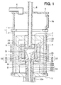
- Hereinafter, an embodiment will be explained. FIG. 1 shows an apparatus for producing silicon carbide single crystals (hereinafter, merely referred to as an apparatus). As shown in FIG. 1,
cylindrical chamber 1 has alower chamber 2 that is a portion to hold a crucible, and anupper chamber 3 that is a portion to take out a completed silicon carbide (SiC) so that space formed in thelower chamber 2 communicates with space formed in theupper chamber 3. - The
upper chamber 3 is composed of, for example, a SUS (stainless steel), and has a sample take-outport 3a for taking out SiC single crystals that finishes crystal growth. An opening at an upper side of theupper chamber 3 is covered with atop lid 4 composed of, for example, the SUS (stainless steel). Anexhaust pipe 6 is connected to thetop lid 4, and is connected to a vacuum pump (not shown). An inside of thechamber 1 is controlled in pressure by the vacuum pump so as to draw a vacuum. - The
lower chamber 2 is composed of, for example, quartz, and an opening at a lower side for thelower chamber 2 is covered with abottom lid 5 composed of, for example, the SUS (stainless steel). Thecrucible 30 is disposed inside thelower chamber 2 and surrounded by a heat insulating material. - The crucible has
first member 31 andsecond member 32. Thefirst member 31 has a cylindrical body (first cylindrical member) . A SiC single crystal substrate fixing pedestal 33 (hereinafter, merely referred to as a pedestal) is disposed at a side close to theupper chamber 3 inside thefirst member 31 so that gap is formed between thepedestal 33 and inner wall of theupper chamber 3. A silicon carbidesingle crystal substrate 34 is fixed on one surface of thepedestal 33. The SiC single crystals grow on the silicon carbidesingle crystal substrate 34 as a seed crystal inspace 35 provided inside thefirst member 31. Hereinafter, the silicon carbidesingle crystal substrate 34 is referred to as a seed crystal, thespace 35 inside thefirst member 31 is referred to as a growth room. - The
second member 32 has a cylindrical body (second cylindrical member) 36 and awall 37. Thewall 37 is provided at an end located far from theupper chamber 3 in thecylindrical body 36. Aprotrusion 38 is provided at a center portion of awall 37 in thesecond member 32. Theprotrusion 38 is provided so as to protrude to the inside of secondcylindrical body 36, and a communicatingpath 38a, which communicates with the inside of the secondcylindrical body 36 to the outside ofsecond member 32, is formed inside theprotrusion 38. The communicatingpath 38a is constituted in such a manner that an opening area of the communicatingpath 38a increases at a portion of the communicatingpath 38a that is closer to thepedestal 34. Thefirst member 31 is disposed inside thesecond member 32 described above. More specifically, thefirst member 31 intervenes between the secondcylindrical body 36 and theprotrusion 38, and a gap is formed between awall 37 and a tip portion of the first member that is located at a side of thewall 37. Thus, theprotrusion 38 is set to protrude from thewall 37 to aseed crystal 34, and a structure is provided in such a manner that the outside of thecrucible 30 communicates with thegrowth room 35 through the communicatingpath 38a. - Incidentally, a portion of the first cylindrical body at the side of the
upper chamber 3 and a portion of the second cylindrical body at the side of theupper chamber 3 are connected with each other to unite with each other. - Such the
crucible 30 is constituted as follows, in other words. That is, thecrucible 30 has a cylindrical member corresponding to the first member 31 a glass-shaped member corresponding to thesecond member 32. The cylindrical member is disposed inside the glass-shaped member, an end portion at an inlet side of the glass-shaped member and one end portion of the cylindrical member are positioned at the same plane, and a gap is formed between the other end portion of the cylindrical member and a bottom of the glass-shaped member. Besides, theprotrusion 38 is formed approximately at a center of a bottom of a glass-shaped member corresponding to thesecond member 32 to protrude to a direction of an open end of the glass-shaped member, and the communicatingpath 38a, which communicates with the outside of thecrucible 30 and a space (growth room 35) formed inside a cylindrical body corresponding to thefirst member 31, is formed in theprotrusion 38. - Incidentally, high purity graphite capable of withstanding high temperature (for example, approximately 2400 °C) can be employed to material for the
first member 31. By using the high purity graphite, it is reduced that impurity comes out from thecrucible 30 and is taken into the crystals during growth. - On the other hand, an
inlet conduit 5 is connected to thewall 37 of the secondcylindrical member 36 so that theinlet conduit 50 communicates with thegrowth room 35. The mixture gas for crystal growth of SiC is introduced to thegrowth room 35 through theinlet conduit 50 and the communicatingpath 38. - The
inlet conduit 50 is constituted in such a manner that a temperature gradient occurs so that a temperature of theinlet conduit 50 rises at a portion in theinlet conduit 50 that is closer to thecrucible 30. In this embodiment, theinlet conduit 50 is composed of three parts. Starting from anoutlet portion 50d where the mixture gas is exhausted into thegrowth room 35, first inlet conduit 50a,second inlet conduit 50b, andthird inlet conduit 50c are arranged in this order. - The first inlet conduit 50a is located at a top portion of the
inlet conduit 50 where theoutlet portion 50d is located, and therefore, disposed close to thecrucible 30. Accordingly, the first inlet conduit 50a is composed of material capable of withstanding high temperature such as, for example, graphite. Firstthermal insulator 51 is disposed so that the temperature gradient occurs in the first inlet conduit 50a. - Moreover, second
thermal insulator 52 is disposed between the first inlet conduit 50a and thecrucible 30. Thus, amount of heat transfer from thecrucible 30 that is heated up to high temperature to the first inlet conduit 50a is reduced, whereby the temperature gradient preferably occurs in the first inlet conduit 50a. - By such the structure, temperature at a portion in the first inlet conduit 50a that is located under the
fist heat insulator 51 can be set at 500 °C. Specially, porous graphite can be employed as a material for the first andsecond heat insulator - The
second inlet conduit 50b is provided to restrain heat conduction from the first inlet conduit 50a to thethird inlet conduit 50c. Therefore, thesecond inlet conduit 50b is composed of a material that has low thermal conductivity such as, for example, quartz. Thethird inlet conduit 50c is composed of, for example, metal, more specially, SUS (stainless steel). Thethird inlet conduit 50c is equipped with, for example, a cooling structure that cools down thethird inlet conduit 50c with water, for example. - Here, when surface roughness Ra is set as an average of difference in dimension between protruding portions and hollow portions at a surface of the inside of the
inlet conduit 50 along a direction perpendicular to the surface thereof, the surface roughness Ra of the inner surface of theinlet conduit 50 is set at 7 µm or less, preferably 1 µm or less. - This is because, especially in the first inlet conduit 50a, temperature of the mixture gas rises at high (for example, 500 °C or more), so that deposits of the mixture gas tend to deposit on the inner surface of the first inlet conduit 50a. Therefore, when the surface roughness Ra is restrained, contact area is reduced where the mixture gas contacts to the inner surface of the first inlet conduit 50a, so that flow velocity of the mixture gas near the inner surface of the
first inlet conduit 50 is prevented from being lowered. As a result, theinlet conduit 50 is prevented from being plugged. - Further, a portion of the
inlet conduit 50 at an opposite side of theoutlet portion 50d penetrates alower lid 5 to reach an external of thechamber 1. Although not shown, a mass flow controller is equipped that is located at a further lower side to control flow of the mixture gas that flows into theinlet conduit 50. Moreover, although not shown, a pyrometer is equipped that is located under theinlet conduit 50 to measure temperature at a surface of the SiC single crystals in process of crystallization or the surface of theseed crystal 34 through theinlet conduit 50. - A lifting shaft (hereinafter, merely referred to as a shaft) 8 is fixed to other side of the
pedestal 33 that is opposite to the side where theseed crystal 34 is fixed, to lift theseed crystal 34 to a direction opposite to a growth direction of the SiC single crystals. Theshaft 8 has a tube shape, a portion thereof close to thecrucible 30 is composed of quartz, and a portion far from thecrucible 30 is composed of SUS (stainless steel). A pyrometer is equipped at an upper side of theshaft 8 to measure temperature of thepedestal 33. Incidentally, theshaft 8 is also surrounded with theheat insulator 7 in the neighborhood of thecrucible 30. - A
temperature rising means 9 is provided outside thechamber 1, which is located at the same level to thecrucible 30. An RF (Radio Frequency)coil 9 is employed as thetemperature rising means 9. In this embodiment, the RF coil has an upper coil and a lower coil independent with each other, so that temperature of an upper portion of thechamber 1 is controlled independent from that of a lower portion of thechamber 1. Moreover, although not shown, an x-ray apparatus is disposed outside thechamber 1. - Next, manufacturing method of SiC single crystals will be explained, which is performed using such the manufacturing apparatus. First, the
seed crystal 34 is fixed on the one surface of thepedestal 33, and disposed at a predetermined position inside thegrowth room 35 by positioning using theshaft 8. - Next, the inside of the
chamber 1 is vacuumed while Ar gas is introduced through theinlet conduit 50. After that, thecrucible 30 is inductively heated up by applying electrical power to theRF coil 9. Then, temperature of thecrucible 30 is stabilized at a predetermined temperature (above 1420 °C that is a temperature in melting point of Si, preferably approximately at 2400 °C where SiC can sublime), and pressure in thecrucible 30 is set at a predetermined pressure. Incidentally, since thecrucible 30 is surrounded with theheat insulator 7, thecrucible 30 is set at high uniform temperature easily. The temperature gradient occurs in theinlet conduit 50 so that temperature therein increases at the portion in theinlet conduit 50 that is closer to thecrucible 30. More specifically, the temperature gradient in theinlet conduit 50 is 100 °C/cm or more on an average from an end portion in the inlet conduit that is disposed at thecrucible 30 to a portion at 500 °C in theinlet conduit 50. This temperature gradient may be further steep, i.e., may be 500 °C/cm or more. - In this embodiment, the first and
second heat insulators crucible 30. The porous graphite is capable of withstanding high temperature and is porous, thereby being prevented from being inductively heated up by theRF coil 9. Therefore, by employing the porous graphite as theheat insulators inlet conduit 50. Incidentally, temperature at a portion in the first inlet conduit 50a under thefirst heat insulator 51 is set approximately at 500 °C. - The mixture gas is introduced into the
crucible 30 with carrier gas through theinlet conduit 50. The mixture gas includes a gas containing Si and a gas containing C. Specially, SiH4, C3H8, H2, and N2 are used as the mixture gas. - In these gases, SiH4 and C3H8 are the gases for forming SiC single crystals. Moreover, H2 forms hydrocarbon by combining with excess carbons at a surface of SiC single crystal so that H2 prevents the surface of SiC single crystal from being carbonized. Moreover, N2 is a dopant gas and introduced to form n-type conductive SiC. Incidentally, trimethylaluminium gas or the like is used and introduced Al to form p-type conductive SiC.
- Incidentally, the carrier gas is used for increasing gas flow in the
inlet conduit 50, and Ar is employed, for example. - As described above, by introducing the mixture gas into the
crucible 30 through theinlet conduit 50 where the temperature gradient occurs, the mixture gas is not heated up rapidly after introduced into thecrucible 30, but the mixture gas at high temperature that is heated up when passing through theinlet conduit 50. Therefore, silicon carbide single crystals having high quality can be formed. - In this case, when the temperature of the mixture gas rises and exceeds such a degree at 500 °C, there is possibility that Si deposits on the inner surface when SiH4 bumps against the inner surface of the
inlet conduit 50. However, the depositions thereof are prevented if the mixture gas is transferred to a high temperature region of the inlet conduit at which temperature thereof is a sublimation point or a melting point of Si and SiC sublime before the depositions thereof occur. The temperature at the high temperature region of the inlet conduit described above is 1800 °C where SiC can sublime. - In this embodiment, the mixture gas is transferred to a higher temperature region by generating the temperature gradient in the
inlet conduit 50. Volume of the mixture gas is expanded as temperature thereof rises. Therefore, the flow velocity of the mixture gas increases as the temperature thereof rises. Moreover, since the carrier gas is mixed with the mixture gas, the flow velocity in theinlet conduit 50 can be faster. - More specifically, a flow velocity of the mixture gas at the end portion of the
inlet conduit 50 that is disposed at the side of thecrucible 30 is preferably 50 cm/s or more, 500 cm/s or more, more desirably. - As described above, the mixture gas can be transferred to the higher temperature region, so that the
inlet conduit 50 is prevented from being plugged with the mixture gas. - Incidentally, the mixture gas that is introduced into the
crucible 30 through theinlet conduit 50 is crystallized on the seed crystal or the SiC single crystals that has already been crystallized on the seed crystal. Crystallinity of the SiC single crystals in this time varies based on crystallinity of theseed crystal 34 or a condition of the temperature in thecrucible 30 or the like, so that the SiC single crystals grow as 4H-SiC or 6H-SiC or the like. - After that, the mixture gas passes through the gap between the
protrusion 38 and the tip portion of thefirst member 31, the gap formed between the tip portion of thefirst member 31 and thewall 37 of the second member 32 (the bottom of the glass-shaped member), and the gap between the outer wall of thefirst member 31 and the inner wall of the secondcylindrical portion 36, then, the mixture gas is exhausted to the outside of thecrucible 30. - Generally, deposits (for example, that are composed of solidified ingredients of polycrystalline silicon or the like in the mixture gas) caused by the mixture gas tend to accumulate on a portion where temperature thereof is lower than other portions on the periphery thereof. Therefore, in this embodiment, by adjusting each output of RF coils that are independent from each other in high and low, temperature of the mixture gas exhausted from the crucible at an exhaust portion of the
crucible 30 is higher than that of the mixture gas introduced into thecrucible 30 at an introducing portion of thecrucible 30. Incidentally, in the embodiment shown in the drawing, the introducing portion denotes a portion in thewall 37 that is connected to theinlet conduit 50, and the exhaust portion denotes the gap formed withfirst member 31 and the secondcylindrical body 36. - As described above, the exhaust portion is prevented from being plugged with the deposits caused by the mixture gas when the mixture gas is exhausted from the
crucible 30 by rising the temperature at the exhaust portion. Namely, since SiC vapor pressure becomes high at a high temperature portion, polycrystalline silicon is prevented from being deposited on the exhaust portion so that the gas is exhausted from thecrucible 30 smoothly. - Then, when the crystal growth is stopped, the mixture gas is stopped being supplied and the temperature is lowered by decreasing electrical power supply of the RF power. After that, the SiC single crystals is transferred to the
upper chamber 3, and pressure in theupper chamber 3 is risen to atmospheric pressure, and then, the SiC single crystals are taken from the sample take-outport 3a. - As described above, a blockage due to the mixture gas at the
inlet conduit 50, and a blockage due to the mixture gas at the exhaust portion are prevented, so that SiC single crystals are grown. - Incidentally, during the crystal growth, temperature of the
seed crystal 34 or the SiC single crystals is measured by the pyrometer equipped beneath theinlet conduit 50, and the temperature can be set under that of thecrucible 30. Therefore, although change in temperature caused by an arrangement ofcrucible 30 andpedestal 33 or by deterioration with heat may occur, the mixture gas can be crystallized on the surface of theseed crystal 34 or the SiC single crystals at constant temperature. - Moreover, since an opening of the communicating
path 38a that is disposed at a side of thegrowth room 35 is larger than that of the communicatingpath 38a that is disposed at a side of theinlet conduit 50, the flow velocity of the mixture gas can be slower around theseed crystal 34. Thus, the mixture gas can stay at around theseed crystal 34 for a long time, so that a lot of SiH4 and C3H8 in the mixture gas can be contributed to form SiC single crystals. - Moreover, since the deposits are prevented from being formed at the
inlet conduit 50 or the exhaust portion of thecrucible 30, the mixture gas is reduced to be used up except the growth of SiC single crystals. - Incidentally, in the manufacturing apparatus described above, the
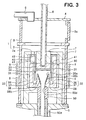
pedestal 33 is connected to theshaft 8 so as to be lifted up to an upper direction (direction of the upper chamber 3) according to progress of the crystal growth of SiC single crystals. Therefore, the crystals can grow long successively. - FIG. 2 shows a schematic cross sectional view of a manufacturing apparatus regarding second embodiment. Hereinafter, different portions from the first embodiment are described mainly, and the same component parts are designated by the same reference numerals so that description thereof is omitted.
- In this embodiment, an
inlet conduit 50 is different in shape of an end portion thereof from that in the first embodiment. As shown in FIG. 2, a sectional area of aninlet conduit 50 decreases at a portion thereof that is closer to acrucible 30. - Thus, since a path of a mixture gas tapers off at a portion of the inlet conduit that is closer to the
crucible 30, flow velocity of the mixture gas increases at the portion of the inlet conduit that is closer to thecrucible 30. Therefore, in comparison with a case in which sectional area of hole in theconduit 50 is constant as the first embodiment, the flow velocity of the mixture gas can further increase at an end portion of theinlet conduit 50, so that blockage caused by the mixture gas in theinlet conduit 50 is prevented. - Incidentally, the
inlet conduit 50 in this embodiment is not constructed with different three parts as the first embodiment, but constructed with one or two parts. In addition, afirst heat insulator 51 is provided at a halfway portion of theinlet conduit 50. Moreover, asecond heat insulator 52 is provided between thecrucible 30 and theinlet conduit 50. By constructing in the manner described above, a temperature gradient may occur in theinlet conduit 50. - Incidentally, although the
inlet conduit 50 in this embodiment is constructed with one or two parts, preferably, surface roughness of an inner surface of theinlet conduit 50 is controlled similarly to the first embodiment at a portion having a temperature gradient. More specifically, since deposits tend to be formed at a portion at which temperature exceeds such a degree at 500 °C, the portion should be controlled in temperature preferably. - Incidentally, a
protrusion 38a is not provided in thecrucible 30. Even if such the structure, SiC single crystals are produced sufficiently. - Further, the gap formed between a
wall 37 and a tip portion of thefirst member 31 is narrowed to such a degree that flow rate of the gas is limited. Therefore, the mixture gas in thegrowth room 35 tends not to be exhausted from thecrucible 30. As a result, the mixture gas stays in thegrowth room 35 for a long time, so that a lot of SiC single crystals are crystallized and grown from the mixture gas. - Incidentally, with regard to the surface roughness Ra of the inner surface in the
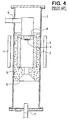
inlet conduit 50, it is not necessarily to control a whole portion where the temperature gradient occurs in theinlet portion 50, but it is preferable to control at least at anexit 50d as a portion where sectional area of the hole in theinlet conduit 50 is smallest so that deposits tend to plug. - FIG. 3 shows a schematic cross sectional view of a manufacturing apparatus regarding third embodiment. Hereinafter, different portions from the first embodiment are described mainly, and the same component parts are designated by the same reference numerals so that description thereof is omitted.
- In this embodiment, a
protrusion 38 is different in shape of a wall surface of a communicatingpath 38a from that in the first embodiment. As shown in FIG. 3, the wall surface of the communicatingpath 38a has a convex and concavity face therein. More specifically, slot-shapedgrooves 38b is formed to face aseed crystal 34. - Generally, when a mixture gas is supersaturated in a
growth room 35, themixture gas 30 bumps against a wall of thecrucible 35, so that deposits are formed on this wall. When the mixture gas is supplied through the communicatingpath 38a of theprotrusion 38 protruding to a side of theseed crystal 34 in thecrucible 30, there is possibility that the deposits are formed on the wall surface of the communicatingpath 38a, so that the deposits fall so as to plug theinlet conduit 50. - However, in this embodiment, by providing the
grooves 38b to the wall surface of the communicatingpath 38a, the deposits are trapped in thegrooves 38b, so that theinlet conduit 50 is prevented from being plugged with the dropped deposits. Moreover, the deposits trapped in thegrooves 38b may be sublimed and used to a growth of SiC. Incidentally, steps may be formed on the wall surface of the communicatingpath 38a instead of thegrooves 38b. - Moreover, in this embodiment, as shown in FIG. 3, a
gas trap 40 is provided at a side of theupper chamber 3 as a room for passing the gas exhausted from thegrowth room 35 through. Thegas trap 40 is lowered in temperature in comparison with thegrowth room 35. Furthermore, in thegas trap 40, anopening 41, which communicates with an exhaust portion of thecrucible 30, is formed on one face located at a side close to thecrucible 30, and anopening 42 is formed on other face located at a side opposite to thecrucible 30. Anopening 7a is formed in aheat insulator 7 so as to be located in accordance with theopening 42. - As described above, since the
gas trap 40 is provided, the mixture gas exhausted from thecrucible 30 passes through thegas trap 40. Since deposits due to the mixture gas tend to accumulate at a portion where temperature is low, the deposits accumulate on thegas trap 40. Therefore, constituents of the mixture gas are solidified so that concentration of the constituents in the mixture gas can be reduced. As a result, anexhaust conduit 6 is prevented from being plugged with the deposits due to the mixture gas. - Furthermore, since the deposits accumulate on a wall of the
gas trap 40, a flow path of the gas in thegas trap 40 is secured sufficiently. Moreover, thegas trap 40 may be provided as a separated body from thecrucible 30 so as to be changed for a new one when amount of the deposits increases. - Incidentally, in the above-mentioned embodiments, although the
heat insulators inlet conduit 50 to cause the temperature gradient therein suitably, as shown in FIG. 3, it is not necessarily to provide theheat insulators - In each embodiment described above, the
RF coil 9 is provided movably. Portions where the deposits based on the mixture gas are formed in thecrucible 30 are checked using an x-ray apparatus, so that temperature of the portions where the deposits are formed rises. - Thus, the deposits are sublimed by increasing the temperature thereof, so that the deposits are reduced, whereby blockage of the
crucible 30 is prevented. - Moreover, TaC or the like is formed on an inner wall of the
inlet conduit 50 to constitute the inner wall of theinlet conduit 50, and a surface roughness of the TaC may be controlled similarly to each above-mentioned embodiment. Specially, as the first embodiment, when a surface roughness Ra of the inner surface of a portion in theinlet conduit 50 that is composed of graphite is controlled, it is preferable that TaC is formed on the inner surface and the surface roughness Ra of the inner surface is controlled. - Further, a surface roughness Ra of an end portion of the inlet conduit 50 (for example, that is composed of graphite) can be controlled, or a surface roughness Ra of an entire inner surface of the
inlet conduit 50 can be controlled. - Further, in the above-mentioned embodiments, although Ar gas is employed as the carrier gas, inert gas such as He or the like can be employed in addition to Ar gas. Furthermore, although H2 gas is included in the mixture gas, H2 gas may be employed as a carrier gas. Since both H2 and He have high thermal conductivity in comparison with SiH4 and C3H8, these gases can absorb heat on the
seed crystal 34 or the SiC single crystals when reaching. Therefore, surface of theseed crystal 34 or the SiC single crystals is cooled down in comparison with thecrucible 30, the crystal growth of SiC is encouraged. - First, the
seed crystal 34 was fixed to thepedestal 33, and disposed at a predetermined place in thecrucible 30. At that time, the seed crystal was disposed so that a (0 0 0 1) Si face of 6H-SiC faces thegrowth room 35. - Then, the
chamber 1 was vacuumed, and Ar was introduced into thechamber 1 at a rate of 10 litres per minute through theinlet conduit 50. Moreover, electrical power was supplied to theRF coil 9, so that the crucible was heated up to 2400 °C. - After that, when temperature of the
crucible 30 became stable at 2400 °C, pressure in thechamber 1 was set at 2.66 x 10⁴ Pa, and the mixture gas and the carrier gas described above were introduced into thecrucible 30 while flows thereof were controlled by the mass flow controller. The flows of SiH4, C3H3, H2 gas, N2, and Ar were set to 1 litre per minute, 0.27 litres per minute, 1 litre per minute, 0.4 litres per minute, and 5 litres per minute, respectively. - During the crystal growth, surface temperature of the
seed crystal 34 or the SiC single crystals grown on theseed crystal 34 were measured by the pyrometer disposed beneath theinlet conduit 50, and controlled to be at 2350 °C. Moreover, temperature distribution and gas concentration distribution were uniformed at the surface of theseed crystal 34 or the SiC single crystals grown on theseed crystal 34 by rotating theshaft 8. - When one hour passed after start of the crystal growth, crystal growth amount was monitored during the crystal growth by observing a transmission image of the
crucible 30 using an x-ray apparatus. As a result, growth rate was at 1.5 mm/hour based on the growth amount. The crystal growth was continued while theshaft 8 was lifted up according to the growth rate. - The crystal growth had been performed for 40 hours as described above, then supplies of SiH4, C3H8, H2 gas, N2, and Ar gases were stopped, and the temperature was decreased by lowering the electric power of the RF power. After that, the SiC single crystals was transferred to the
upper chamber 3, and pressure in theupper chamber 3 was risen to atmospheric pressure, and then, the SiC single crystals were taken from the sample take-outport 3a. - After the experiment described above, the growth amount of the SiC single crystals was measured to be at 57 mm. The fact was found that a taken-out ingot of the SiC single crystals had temperature distribution and gas concentration distribution symmetrically with respect to a center thereof since the ingot had a facet of a (0 0 0 1) face at a grown surface thereof.
- Moreover, a wafer having a thickness of 500 µm was sliced from the SiC single crystals and was polished. The SiC wafer was checked in Raman scattering spectroscopy characteristic, then, the wafer had a poly type of 6H-SiC. Besides, emission distribution on a plane of the wafer was checked by radiating He-Cd laser (325 nm) to the SiC wafer, then, the SiC wafer had the same poly type of 6H-SiC at whole surface thereof.
- While the present invention has been shown and described with reference to the foregoing preferred embodiment, it will be apparent to those skilled in the art that changes in form and detail may be therein without departing from the scope of the invention as defined in the appended claims.
an inlet conduit (50) for introducing a mixture gas having a gas including Si and a gas including C into the crucible, so that silicon carbide single crystals grow on said silicon carbide single-crystal substrate, into the crucible; the inlet conduit having a first heat insulator (51) provided at a halfway portion of the inlet conduit for setting the temperature gradient in the inlet conduit at 100°C/cm or more on an average from an end portion in the inlet conduit that is disposed at the crucible to a portion at 500°C in the inlet conduit.
Claims (24)
- A manufacturing method for producing silicon carbide single crystals, comprising:providing a silicon carbide single-crystal substrate (34) as a seed crystal (34) in a crucible (30);introducing a mixture gas having a gas including Si and a gas including C into said crucible, whereby silicon carbide single crystals grow on said silicon carbide single-crystal substrate, characterized in that:wherein the temperature gradient in the inlet conduit is set at 100°C/cm or more on an average from an end portion in the inlet conduit that is disposed at the crucible to a portion at 500 °C in the inlet conduit.a temperature gradient occurs in an inlet conduit (50) for introducing the mixture gas so that a temperature of the inlet conduit rises at a portion of the inlet conduit that is closer to the crucible,
- A manufacturing method for producing silicon carbide single crystals according to claim 1, wherein:a conduit having a hole whose sectional area is smaller at a portion thereof that is closer to the crucible as the inlet conduit.
- A manufacturing method for producing silicon carbide single crystals according to claim 1 or 2, wherein:a temperature gradient in the inlet conduit is set at 500°C/cm or more on an average from an end portion in the inlet conduit that is disposed at the crucible to a portion at 500 °C in the inlet conduit.
- A manufacturing method for producing silicon carbide single crystals according to any one of claims 1 to 3, wherein: a flow velocity of the mixture gas at an end portion of the inlet conduit that is disposed at a side of the crucible is set at 50 cm/s or more.
- A manufacturing method for producing silicon carbide single crystals according to any one of claims 1 to 4, wherein: a flow velocity of the mixture gas at an end portion of the inlet conduit that is disposed at a side of the crucible is set at 500 cm/s or more.
- A manufacturing method for producing silicon carbide single crystals according to claim 1,
characterized in that:the mixture gas is mixed with a carrier gas, then, the mixture gas and the carrier gas are introduced into crucible through an inlet conduit (50) for introducing the mixture gas into the crucible. - A manufacturing method for producing silicon carbide single crystals according to claim 6, wherein:a flow rate including the mixture gas and the carrier gas in the inlet conduit is bigger than that of a gas composed only of the mixture gas in the inlet conduit.
- A manufacturing method for producing silicon carbide single crystals according to claim 6 or 7, wherein:the carrier gas is composed at least one of hydrogen and inert gas.
- A manufacturing method for producing silicon carbide single crystals according to any one of claims 1 to 8, wherein
a temperature at an exhaust portion of the crucible through which the mixture gas is introduced into the crucible is set higher than that at an introducing portion of the crucible through which the mixture gas is exhausted from the crucible. - A manufacturing method for producing silicon carbide single crystals according to any one of claims 1 to 9, further characterized by
checking a portion in the crucible where deposits caused by the mixture gas are formed using an x-ray apparatus provided outside of the crucible; and
rising a temperature of the portion in the crucible with a temperature rising means (9) provided outside of the crucible, which is movable with respect to the crucible, by shifting the temperature rising means. - A manufacturing method for producing silicon carbide single crystals according to any one of claims 1 to 10, further characterized by
passing the mixture gas that is exhausted from a growth room (35) where growth of silicon carbide single crystals on the silicon carbide single-crystal substrate is performed in the crucible through a room (40),
wherein a temperature of the room is set lower than that of the growth room. - A manufacturing apparatus for producing silicon carbide single crystals comprising:a crucible (30) for disposing a silicon carbide single-crystal substrate (34) therein as a seed crystal (34),wherein
an inlet conduit (50) for introducing a mixture gas having a gas including Si and a gas including C into the crucible,so that silicon carbide single crystals grow on said silicon carbide single-crystal substrate, into the crucible; the inlet conduit having a first heat insulator (51) provided at a halfway portion of the inlet conduit for setting the temperature gradient in the inlet conduit at 100°C/cm or more on an average from an end portion in the inlet conduit that is disposed at the crucible to a portion at 500°C in the inlet conduit. - A manufacturing apparatus for producing silicon carbide single crystals according to claim 12, wherein:materials composed of the inlet conduit (50) are arranged in order of graphite, quartz, and metal from an outlet portion (50d) where the mixture gas is exhausted into the crucible.
- A manufacturing apparatus for producing silicon carbide single crystals according to claim 12 and/or 13, wherein:a sectional area of a hole of the inlet conduit (50) is reduced at a portion of the inlet conduit that is closer to the crucible.
- A manufacturing apparatus for producing silicon carbide single crystals according to any one of claims 12 to 14, wherein:a second heat insulator (52) is provided between the inlet conduit and the crucible.
- A manufacturing apparatus for producing silicon carbide single crystals according to any one of claims 12 to 15, wherein:the surface roughness Ra is 7 µm or less at least at an inner surface of an outlet portion (50d) in the inlet conduit where the mixture gas is exhausted from the inlet conduit to the crucible.
- A manufacturing apparatus for producing silicon carbide single crystals according to any one of claims 12 to 16, wherein:TaC is formed on an inner surface of an outlet portion (50d) in the inlet conduit where the mixture gas is exhausted from the inlet conduit to the crucible, and a surface roughness Ra of the TaC is 7 µm or less.
- A manufacturing apparatus for producing silicon carbide single crystals according to claim 16 or 17, wherein:the inner surface of the outlet portion in the inlet conduit has a polished surface.
- A manufacturing apparatus for producing silicon carbide single crystals according to any of claims 16 to 18, wherein: the inner surface of the outlet portion in the inlet conduit has a mirror surface.
- A manufacturing apparatus for producing silicon carbide single crystals according to claim 18 or 19, wherein: a surface roughness Ra of the inner surface of the outlet portion in the inlet conduit has a polished surface is 1 µm or less.
- A manufacturing apparatus for producing silicon carbide single crystals according to claim 12, wherein
a protrusion (38) is formed inside the crucible so as to protrude to a side of the silicon carbide single-crystal substrate, the protrusion having a communicating path (38a) which connects the inlet conduit (50) to introduce the mixture gas into the crucible to a growth room (35) where growth of silicon carbide single crystals on the silicon carbide single-crystal substrate is performed in the crucible;
wherein an opening area of the communicating path increases at a portion of the communicating path that is closer to the silicon carbide single-crystal substrate, and a wall surface of the communicating path has a convex and concavity thereon. - A manufacturing apparatus for producing silicon carbide single crystals according to claim 12, further
characterized by
a structure in which a temperature at an exhaust portion of the crucible through which the mixture gas is exhausted from the crucible is higher than that at an introducing portion of the crucible through which the mixture gas is introduced into the crucible. - A manufacturing apparatus for producing silicon carbide single crystals according to claim 12, further
characterized by
a temperature rising means (9) movably disposed outside the crucible; and
an x-ray apparatus disposed outside the crucible. - A manufacturing apparatus for producing silicon carbide single crystals according to claim 12, further
characterized by
a room (40) for passing the mixture gas therein that is exhausted from a growth room (35) where growth of silicon carbide single crystals on the silicon carbide single-crystal substrate is performed in the crucible,
wherein a temperature of the room is set lower than that of the growth room.
Applications Claiming Priority (2)
| Application Number | Priority Date | Filing Date | Title |
|---|---|---|---|
| JP2000343664 | 2000-11-10 | ||
| JP2000343664A JP3864696B2 (en) | 2000-11-10 | 2000-11-10 | Method and apparatus for producing silicon carbide single crystal |
Publications (2)
| Publication Number | Publication Date |
|---|---|
| EP1205583A1 EP1205583A1 (en) | 2002-05-15 |
| EP1205583B1 true EP1205583B1 (en) | 2007-01-03 |
Family
ID=18817997
Family Applications (1)
| Application Number | Title | Priority Date | Filing Date |
|---|---|---|---|
| EP01126619A Expired - Lifetime EP1205583B1 (en) | 2000-11-10 | 2001-11-07 | Manufacturing method for producing silicon carbide crystal using source gases and apparatus for the same |
Country Status (4)
| Country | Link |
|---|---|
| US (2) | US6830618B2 (en) |
| EP (1) | EP1205583B1 (en) |
| JP (1) | JP3864696B2 (en) |
| DE (1) | DE60125689T2 (en) |
Families Citing this family (24)
| Publication number | Priority date | Publication date | Assignee | Title |
|---|---|---|---|---|
| EP1322801B1 (en) * | 2000-09-22 | 2010-01-06 | Aixtron Ag | Cvd-method and gas inlet mechanism for carrying out the method |
| FR2839730B1 (en) * | 2002-05-15 | 2004-08-27 | Centre Nat Rech Scient | SINGLE CRYSTAL SILICON CARBIDE FORMATION |
| SE525574C2 (en) * | 2002-08-30 | 2005-03-15 | Okmetic Oyj | Low-doped silicon carbide substrate and its use in high-voltage components |
| DE10243022A1 (en) * | 2002-09-17 | 2004-03-25 | Degussa Ag | Separation of a solid by thermal decomposition of a gaseous substance in a cup reactor |
| US7217323B2 (en) * | 2003-04-04 | 2007-05-15 | Denso Corporation | Equipment and method for manufacturing silicon carbide single crystal |
| DE602004001802T3 (en) * | 2003-04-24 | 2012-01-26 | Norstel Ab | Apparatus and method for producing single crystals by vapor deposition |
| ITMI20031196A1 (en) * | 2003-06-13 | 2004-12-14 | Lpe Spa | SYSTEM FOR GROWING SILICON CARBIDE CRYSTALS |
| US20050252449A1 (en) * | 2004-05-12 | 2005-11-17 | Nguyen Son T | Control of gas flow and delivery to suppress the formation of particles in an MOCVD/ALD system |
| EP1806437B1 (en) * | 2004-09-03 | 2016-08-17 | Nippon Steel & Sumitomo Metal Corporation | Method for preparing silicon carbide single crystal |
| GB2423307A (en) * | 2005-02-22 | 2006-08-23 | Univ Durham | Apparatus and process for crystal growth |
| US20100006859A1 (en) * | 2006-07-19 | 2010-01-14 | Gilyong Chung | Method of Manufacturing Substrates Having Improved Carrier Lifetimes |
| US8197596B2 (en) * | 2006-07-28 | 2012-06-12 | Pronomic Industry Ab | Crystal growth method and reactor design |
| US7351936B1 (en) * | 2007-01-22 | 2008-04-01 | Taiwan Semiconductor Manufacturing Company | Method and apparatus for preventing baking chamber exhaust line clog |
| US8016945B2 (en) * | 2007-12-21 | 2011-09-13 | Applied Materials, Inc. | Hafnium oxide ALD process |
| TW200930850A (en) * | 2008-01-03 | 2009-07-16 | Green Energy Technology Inc | Cooling structure for body of crystal growth furnace |
| JP4591523B2 (en) * | 2008-03-05 | 2010-12-01 | 株式会社デンソー | Silicon carbide single crystal manufacturing equipment |
| DE102008042499A1 (en) * | 2008-09-30 | 2010-04-01 | Evonik Degussa Gmbh | Process for the preparation of high purity silicon carbide from carbohydrates and silica by calcining |
| KR20120082873A (en) * | 2009-09-15 | 2012-07-24 | 투-식스 인코포레이티드 | Sublimation growth of sic single crystals |
| JP4992965B2 (en) * | 2009-12-25 | 2012-08-08 | 株式会社デンソー | Silicon carbide single crystal manufacturing equipment |
| DE102011089501B4 (en) * | 2011-12-21 | 2013-10-10 | Freiberger Compound Materials Gmbh | Apparatus and method for vaporizing material from a molten metal |
| JP6269854B2 (en) * | 2014-10-31 | 2018-01-31 | 富士電機株式会社 | Method for growing silicon carbide epitaxial film |
| EP3026013A1 (en) | 2014-11-28 | 2016-06-01 | Evonik Degussa GmbH | Nanocrystalline metal compound powder, method for their preparation and use of same |
| EP3026012A1 (en) | 2014-11-28 | 2016-06-01 | Evonik Degussa GmbH | High purity, amorphous metal compound powders, method for the preparation and use of same |
| CN114108078B (en) * | 2021-11-30 | 2023-06-02 | 江苏集芯半导体硅材料研究院有限公司 | Crucible assembly and single crystal growth apparatus having the same |
Family Cites Families (16)
| Publication number | Priority date | Publication date | Assignee | Title |
|---|---|---|---|---|
| JPH05208900A (en) | 1992-01-28 | 1993-08-20 | Nisshin Steel Co Ltd | Apparatus for growing silicon carbide single crystal |
| JP3281019B2 (en) * | 1992-01-30 | 2002-05-13 | 同和鉱業株式会社 | Method and apparatus for producing zinc particles |
| DE4310744A1 (en) * | 1993-04-01 | 1994-10-06 | Siemens Ag | Device for producing SiC single crystals |
| SE9502288D0 (en) * | 1995-06-26 | 1995-06-26 | Abb Research Ltd | A device and a method for epitaxially growing objects by CVD |
| US6030661A (en) | 1995-08-04 | 2000-02-29 | Abb Research Ltd. | Device and a method for epitaxially growing objects by CVD |
| US5683507A (en) * | 1995-09-05 | 1997-11-04 | Northrop Grumman Corporation | Apparatus for growing large silicon carbide single crystals |
| SE9503426D0 (en) * | 1995-10-04 | 1995-10-04 | Abb Research Ltd | A device for heat treatment of objects and a method for producing a susceptor |
| SE9503428D0 (en) * | 1995-10-04 | 1995-10-04 | Abb Research Ltd | A method for growing epitaxially and a device for such growth |
| US6039812A (en) | 1996-10-21 | 2000-03-21 | Abb Research Ltd. | Device for epitaxially growing objects and method for such a growth |
| JP3079256B2 (en) | 1997-07-18 | 2000-08-21 | 工業技術院長 | Crystal growth method |
| US6056820A (en) * | 1998-07-10 | 2000-05-02 | Northrop Grumman Corporation | Advanced physical vapor transport method and apparatus for growing high purity single crystal silicon carbide |
| DE19934336A1 (en) * | 1998-09-03 | 2000-03-09 | Siemens Ag | High temperature silicon carbide semiconductor substrate production and treatment apparatus, especially for silicon carbide epitaxy, has a susceptor completely covered by a cover plate and the substrate |
| US6063185A (en) * | 1998-10-09 | 2000-05-16 | Cree, Inc. | Production of bulk single crystals of aluminum nitride, silicon carbide and aluminum nitride: silicon carbide alloy |
| RU2162117C2 (en) | 1999-01-21 | 2001-01-20 | Макаров Юрий Николаевич | Method of epitaxial growth of silicon carbide single crystals and reactor for its embodiment |
| US6406539B1 (en) * | 1999-04-28 | 2002-06-18 | Showa Denko K.K, | Process for producing silicon carbide single crystal and production apparatus therefor |
| US6451112B1 (en) * | 1999-10-15 | 2002-09-17 | Denso Corporation | Method and apparatus for fabricating high quality single crystal |
-
2000
- 2000-11-10 JP JP2000343664A patent/JP3864696B2/en not_active Expired - Lifetime
-
2001
- 2001-11-01 US US09/985,120 patent/US6830618B2/en not_active Expired - Lifetime
- 2001-11-07 DE DE60125689T patent/DE60125689T2/en not_active Expired - Lifetime
- 2001-11-07 EP EP01126619A patent/EP1205583B1/en not_active Expired - Lifetime
-
2004
- 2004-06-22 US US10/872,365 patent/US7112242B2/en not_active Expired - Lifetime
Also Published As
| Publication number | Publication date |
|---|---|
| US20020056411A1 (en) | 2002-05-16 |
| JP2002154899A (en) | 2002-05-28 |
| DE60125689D1 (en) | 2007-02-15 |
| US20040231583A1 (en) | 2004-11-25 |
| EP1205583A1 (en) | 2002-05-15 |
| DE60125689T2 (en) | 2007-10-11 |
| JP3864696B2 (en) | 2007-01-10 |
| US7112242B2 (en) | 2006-09-26 |
| US6830618B2 (en) | 2004-12-14 |
Similar Documents
| Publication | Publication Date | Title |
|---|---|---|
| EP1205583B1 (en) | Manufacturing method for producing silicon carbide crystal using source gases and apparatus for the same | |
| EP1205584B1 (en) | Manufacturing method for producing silicon carbide crystal using source gases and apparatus for the same | |
| EP1471168B1 (en) | Device and method for producing single crystals by vapour deposition | |
| JP3165685B2 (en) | Sublimation growth of silicon carbide single crystal | |
| US6391109B2 (en) | Method of making SiC single crystal and apparatus for making SiC single crystal | |
| US9068277B2 (en) | Apparatus for manufacturing single-crystal silicon carbide | |
| CN112176405B (en) | System for horizontally growing high-quality semiconductor single crystal and method for producing the single crystal | |
| US20230120928A1 (en) | System For Efficient Manufacturing Of A Plurality Of High-Quality Semiconductor Single Crystals, And Method Of Manufacturing Same | |
| KR100749860B1 (en) | Apparatus for growing single crystal and method for growing single crystal | |
| JP5761264B2 (en) | Method for manufacturing SiC substrate | |
| JP4293109B2 (en) | Method for producing silicon carbide single crystal | |
| JP2004043211A (en) | PROCESS AND APPARATUS FOR PREPARING SiC SINGLE CRYSTAL | |
| KR200412993Y1 (en) | Apparatus for growing single crystal |
Legal Events
| Date | Code | Title | Description |
|---|---|---|---|
| PUAI | Public reference made under article 153(3) epc to a published international application that has entered the european phase |
Free format text: ORIGINAL CODE: 0009012 |
|
| AK | Designated contracting states |
Kind code of ref document: A1 Designated state(s): AT BE CH CY DE DK ES FI FR GB GR IE IT LI LU MC NL PT SE TR |
|
| AX | Request for extension of the european patent |
Free format text: AL;LT;LV;MK;RO;SI |
|
| 17P | Request for examination filed |
Effective date: 20020611 |
|
| 17Q | First examination report despatched |
Effective date: 20021115 |
|
| AKX | Designation fees paid |
Designated state(s): DE FI SE |
|
| GRAP | Despatch of communication of intention to grant a patent |
Free format text: ORIGINAL CODE: EPIDOSNIGR1 |
|
| GRAS | Grant fee paid |
Free format text: ORIGINAL CODE: EPIDOSNIGR3 |
|
| GRAA | (expected) grant |
Free format text: ORIGINAL CODE: 0009210 |
|
| AK | Designated contracting states |
Kind code of ref document: B1 Designated state(s): DE FI SE |
|
| REF | Corresponds to: |
Ref document number: 60125689 Country of ref document: DE Date of ref document: 20070215 Kind code of ref document: P |
|
| REG | Reference to a national code |
Ref country code: SE Ref legal event code: TRGR |
|
| PLBE | No opposition filed within time limit |
Free format text: ORIGINAL CODE: 0009261 |
|
| STAA | Information on the status of an ep patent application or granted ep patent |
Free format text: STATUS: NO OPPOSITION FILED WITHIN TIME LIMIT |
|
| 26N | No opposition filed |
Effective date: 20071005 |
|
| PGFP | Annual fee paid to national office [announced via postgrant information from national office to epo] |
Ref country code: DE Payment date: 20201119 Year of fee payment: 20 Ref country code: FI Payment date: 20201119 Year of fee payment: 20 Ref country code: SE Payment date: 20201125 Year of fee payment: 20 |
|
| REG | Reference to a national code |
Ref country code: DE Ref legal event code: R071 Ref document number: 60125689 Country of ref document: DE |
|
| REG | Reference to a national code |
Ref country code: FI Ref legal event code: MAE |
|
| REG | Reference to a national code |
Ref country code: SE Ref legal event code: EUG |