The present invention relates to a temperature-stabilized optical
amplifier for optical telecommunications and to a method for temperature-stabilizing
an optical amplifier. In particular, the present invention relates to a
temperature-stabilized fiber-optic amplifier suitable for metropolitan optical
networks, i.e. optical networks typically adapted to transmit signals at
distances of some kilometers or some tenths of kilometers (up to about 300
km).
As known, fiber-optic telecommunication systems are usually equipped
with fiber-optic amplifier for the amplification of optical signals. A fiber-optic
amplifier typically comprises an active optical fiber that is opportunely doped
with ions of a rare-earth element such as, for example, erbium, and that is
serially connected to a transmission fiber adapted to convey optical signals.
The energy structure of erbium ions is such that signal light with wavelength of
approximately 1530-1565 nm can be amplified in the fiber if the population of
the excited states of the erbium ions is such that rate of stimulated emission
exceeds that of spontaneous emission and absorption. In such a
circumstance, light within the gain bandwidth entering the optical fiber will
experience net gain, and will exit the fiber with greater power.
An optical pump source, coupled to the wave-guiding portion of the
optical fiber, provides a pump radiation to the active fiber in order to excite the
dopant ions onto an excited state. In the case of erbium doping, a high-power
diode laser with emission to approximately 980 nm is typically used. Pumping
at this wavelength results in low noise figure amplifiers. The relatively small
cross-sectional area of the wave-guiding portion of the optical fiber helps to
ensure high intensity pumping and therefore allows appreciable gain of the
signal wavelengths. However, the properties of the signal produced by such
an amplifier will depend to a large extent on the properties of the diode laser
used to pump the fiber.
In a practical system, the diode lasers are permanently and robustly
connected by an opto-mechanical apparatus to a length of undoped optical
fiber, which in turn is connected to the doped fiber in the optical amplifier. The
assembly consisting of the diode laser, the opto-mechanical apparatus and
the undoped optical fiber is called a pigtailed diode laser. Presently, many
pigtailed diode lasers have undesirable characteristics such as wavelength
and intensity instabilities that create noise in the pumped system. One of the
most troublesome sources of diode laser noise in 980 nm diode lasers is
wavelength fluctuation caused by changes in temperature. This dependency
is substantially linear, and a typical value of the ratio between the emission
wavelength variation and temperature is about 0.33 nm/°C. These
wavelength emission variations make erbium amplifiers unstable within the
usual working temperature range, i.e. approximately between 0 and 65 °C.
It is known that the gain G of an erbium-doped amplifier is a function of
the absorbed pump power, which depends on the pump absorption coefficient
α(λ) of the active fiber at the pump wavelength λ. In turn, the pump absorption
coefficient α(λ) can be expressed as:
α(λ) = 10 · log e σ(λ)N t ΓL
where σ(λ) is the absorption cross-section, Nt is the erbium ion concentration,
Γ is the confinement factor (fraction of the optical power contained in the
core), and L is the length of the active fiber.
As the pump wavelength λ varies, the pump absorption coefficient α(λ)
and, therefore, the absorbed pump power, vary in accordance with the new
value of the pump absorption coefficient at that new wavelength. Fig. 1 shows
the typical curve of pump absorption coefficient vs. emission wavelength and
the shift of the working points A and B of two different laser diodes into new
working points A' and B' as the temperature increases. When the temperature
varies, the absorbed power fraction of the active fibers varies in accordance to
the position of the working point of the laser diode on the depicted curve.
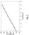
Fig. 2 illustrates the linear dependency (with a slope of approximately 0.33
nm/°C) of the emission wavelength on temperature for a typical laser diode.
The Applicant has verified that an optical amplifier comprising an active
fiber having a peak absorption of 5 dB and pumped by a single laser pump
that is not stabilized can experience a pump absorption variation of more than
3.5 dB when the temperature varies in the temperature range 0-65°C.
Applicant has also noticed that laser diodes of a same type, even when
obtained from the same manufacturing process, usually have slightly different
emission wavelengths due to manufacturing tolerance.
In order to improve the temperature-insensitivity of the amplifier, the
working temperature of the laser diode can be stabilized by using a Peltier
cell, as suggested for example in US 4,571,728, and the emission wavelength
of the laser diode can be stabilized by using a fiber Bragg grating, as
suggested for example in US 5,485,481.
Applicant observes that these techniques add cost and complexity to
the amplifier while, especially in the case of metropolitan optical networks, it is
important to reduce the cost of the system to a minimum.
US 5,287,216 relates to an erbium-doped fiber optic amplifier in which
the doped fiber is simultaneously pumped by multiple pump lasers generating
optical waves of differing wavelengths. The optical waves are combined using
a wavelength division multiplexer (WDM) before introduction into the doped
fiber. The WDM used for the experimental measures can combine any pump
between 960 and 975 nm with another in the 985 and 1000 nm range.
The Applicant observes that, due to the use of WDM for coupling the
different wavelengths, the pump arrangement of US 5,287,216 has relatively
limited tolerance intervals for the pump wavelength, and requires to duplicate
the number of pump sources if an active fiber has to be pumped bidirectionally
or if two different active fibers have to be pumped.
The Applicant has faced the problem of providing an optical amplifier
for an optical transmission system, in particular a fiber-optic amplifier suitable
for metropolitan networks, that is stable with respect to temperature, cheap
and simple, and that has an efficient and versatile pumping system. In
particular, the Applicant has considered the problem of temperature-stabilizing
an optical amplifier without carrying out a stabilization of the pump sources,
which is usually an expensive operation.
The Applicant has found that an efficient way to temperature-stabilizing,
in a predetermined temperature range, an optical amplifier comprising a set of
active waveguides having a pump absorption coefficient showing a maximum
at a predetermined wavelength, is to pump the set of active waveguides by a
mixed pump radiation comprising at least a first and a second pump
wavelength lower and, respectively, higher than said predetermined
wavelength at an intermediate temperature of said temperature range. In this
way, as the temperature varies, the amplifier's pump absorption coefficients at
the different pump wavelengths vary with opposite signs, and the total gain of
the amplifier remains substantially unchanged. The mixed pump radiation can
be generated by mixing a plurality of pump beams by means of a set of optical
couplers, which also split the mixed pump radiation into a plurality of power
fractions used to pump at least one active waveguide bidirectionally, or at
least two active waveguides monodirectionally.
This pumping scheme allows achieving a relatively high temperature-stability
of the amplifier emission power, without requiring any technique for
the temperature stabilization and/or the wavelength stabilization of the pump
sources, and without the need of selecting a restricted subset of the
manufactured pump laser diodes. Moreover, the proposed pumping
arrangement is particularly versatile and reduces to a minimum the number of
pump sources required to pump a predetermined number of active
waveguides.
The technique of the present invention is advantageously applicable to
erbium-doped fiber optical amplifiers, since for an erbium-doped fiber the
relation between the pump absorption coefficient and the pump wavelength is
represented by a substantially triangular curve (having a maximum at
approximately 978 nm).
According to a first aspect, the present invention relates to an optical
amplifier temperature-stabilized in a predetermined temperature range,
comprising:
The at least one optical coupler is preferably a wavelength-independent
optical coupler.
The set of active waveguides preferably comprises at least one active
fiber.
The set of active waveguides preferably comprises at least one erbium-doped
active waveguide.
The at least two outputs of the at least one optical coupler can be
optically coupled to at least two different active waveguides of the set of active
waveguides. Alternatively, the at least two outputs of the at least one optical
coupler can be optically coupled to opposite ends of a same active waveguide
of the set of active waveguides, for feeding the respective power fractions of
the mixed pump radiation to said same active waveguide bidirectionally.
The set of optical couplers can comprise a first and a second subset of
optical couplers, each optical coupler of the first subset having a plurality of
inputs optically coupled to respective pump sources of the set of pump
sources; and each optical coupler of the second subset having a plurality of
inputs optically coupled to respective outputs of respective optical couplers of
the first subset, and a plurality of outputs optically coupled to at least one
active waveguide of the set of active waveguides.
The at least one optical coupler can be a 3 dB optical coupler.
The wavelength distance between the first and the second pump
wavelength is preferably comprised between 10 and 30 nm, more preferably
comprised between 10 and 20 nm.
According to a second aspect, the present invention relates to an
optical telecommunication system, comprising an optical transmitter, an
optical receiver, and a fiber optic line optically connecting the optical
transmitter to the optical receiver and comprising a temperature-stabilized
optical amplifier as previously defined.
According to a further aspect, the present invention relates to a method
for temperature-stabilized amplification of optical signals in a predetermined
temperature range, comprising:
The step of feeding each of the two power fractions to an active
waveguide can comprise feeding the two power fractions to two different
active waveguides, or to a same active waveguide bidirectionally
The active waveguide is preferably an optical fiber.
The active waveguide is preferably doped with erbium.
The wavelength distance between the first and the second pump
wavelength is preferably comprised between 10 and 30 nm.
Advantageously, the first and the second pump wavelengths can have
substantially the same wavelength distance from the predetermined
wavelength at a temperature in the middle of the predetermined temperature
range.
Further features and advantages of the present invention will appear
more clearly from the following detailed description of some preferred
embodiments, made with reference to the attached drawings. In such
drawings:
- Figure 1 shows the typical curve of absorption coefficient vs. emission
wavelength for an erbium-doped active fiber;
- Figure 2 illustrates a typical linear dependency of the emission
wavelength on temperature for an erbium-doped active fiber;
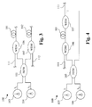
- Figure 3 shows a first embodiment of an optical amplifier according to
the present invention, including two pumps;
- Figure 4 shows a second embodiment of an optical amplifier according
to the present invention, including two pumps;
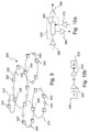
- Figure 5 shows a third embodiment of an optical amplifier according to
the present invention, including four pumps;
- Figure 6 illustrates an experimental setup for testing a two-pumps
amplifier according to the present invention;
- Figures 7a-7f show the results of experimental tests;
- Figure 8 show the result of a numeric simulation;
- Figure 9 illustrates an optical metropolitan network including optical
amplifiers according to the present invention; and
- Figures 10a and 10b show different possible applications of an optical
amplifier in the optical metropolitan network of Fig. 9.
An optical amplifier 100 according to the present invention is shown in
Fig. 3. Amplifier 100 is adapted to amplify signals transmitted in a first and a
second optical fiber 111, 112, having the same or opposite transmission
directions. For example, the first and the second optical fibers 111, 112 may
be the transmission fibers of a bi-directional transmission system.
Amplifier 100 includes a first and a second erbium-doped active fiber
101, 102, serially connected to the first and, respectively, the second optical
fiber 111, 112 for the amplification of optical signals transmitted therein.
Amplifier 100 further includes a first and a second pump laser 103, 104
for generating a first pump beam at a first wavelength λ1 and, respectively, a
second pump beam at a second wavelength λ2, both suitable to excite the
erbium ions. Pump lasers 103, 104 are laser diodes, for example model
LDM0980 manufactured by Pirelli.
As previously stated, the emission wavelengths λ1 and λ2 are function
of the temperature of the pump laser 103, 104. Typically, the correct
functioning of laser diodes should be guaranteed in the range of temperature
between 0°C and 65°C. According to the present invention, at temperatures
in the middle of this range, the wavelengths λ1 and λ2 must be lower and,
respectively, higher than the wavelength λp corresponding to the peak of the
curve of the pump absorption coefficient vs. emission wavelength of the active
fiber, i.e. approximately 978 nm. Preferably, the wavelengths λ1 and λ2 have
substantially the same wavelength distance from the wavelength λp at a
temperature of 32.5°C (in the middle of the considered temperature range).
This wavelength distance is preferably comprised between 5 and 15 nm, more
preferably between 5 and 10 nm. Therefore, the wavelength distance
between λ1 and λ2 is preferably comprised between 10 and 30 nm, more
preferably between 10 and 20 nm.
A pump distribution device 105 optically couples the first and the
second pump laser 103, 104 to the first and the second active fiber 101, 102.
The pump distribution device 105 may comprise a 3dB coupler, for generating
a mixed pump radiation from the first and the second pump beam, and for
providing part of the mixed pump radiation to the first active fiber 101 and part
to the second active fiber 102. The mixed pump radiation comprises
approximately half of the power of the first pump beam and half of the power
of the second pump beam. More in details, the 3dB coupler 105 has a first
input coupled to the first pump laser 103 for receiving the first pump beam; a
second input coupled to the second pump laser 104 for receiving the second
pump beam; a first output optically coupled to the first active fiber 101 via a
first WDM coupler 106, for providing to the first active fiber 101 a first power
fraction of the mixed pump radiation; and a second output optically coupled to
the second active fiber 102 via a second WDM coupler 107, for providing to
the second active fiber 102 a second power fraction of the mixed pump
radiation. The 3dB coupler 105 can be, for example, model
SMFC7250ASB10 manufactured by E-TEK.
The first WDM coupler 106 has a first input coupled to the first
transmission fiber 111, a second input coupled to the first output of the 3dB
coupler 105 and an output coupled to the first active fiber 101. The second
WDM coupler 107 has a first input coupled to the second transmission fiber
112, a second input coupled to the second output of the 3dB coupler 105 and
an output coupled to the second active fiber 102. WDM couplers 106, 107
can be 980/1550 WDM couplers, for example model SWDM0915SPR
manufactured by E-TEK.
Amplifier 100 operates as follows. The first and the second pump
beam generated by the first and, respectively, the second pump laser 103,
104, are fed to the 3dB coupler 105, which mixes them and generates the
mixed pump radiation. The 3dB coupler 105 also splits the mixed pump
radiation into the first and the second power fraction. As previously described,
the mixed pump radiation has half of its power at the first wavelength λ1 and
half at the second wavelength λ2. The two fractions of the mixed pump
radiation are fed to the first and the second active fiber 101, 102 via the first
and, respectively, the second WDM coupler 106, 107, together with the
transmission signals conveyed by the first and the second transmission fibers
111, 112. Hence, each active fibers 101, 102 is pumped at both the first and
the second wavelength λ1, λ2, and is therefore stabilized in temperature. In
fact, as the temperature varies, the pump powers absorbed by the active fiber
from the first diode laser and from the second diode lasers vary substantially
of the same quantity ΔP but in opposite directions, and the total absorbed
pump power remain substantially constant.
For example, an increase ΔT in temperature would produce a shift of
the first wavelength λ1 towards λp and a shift of the second wavelength λ2
away from λp, with respective contributes +ΔPp and -ΔPp to the absorbed
pump radiation, and respective contributes +ΔG and -ΔG to the gain of the
amplifier. This trend is valid only until λ1 and λ2 are on opposite parts with
respect to λp, i.e. only within a limited range of temperature that depends on
the wavelength distance of λ1 and λ2 from λp.
The Applicant has-verified that if the wavelength distance Δλ between
λ1 and λ2 is at least 21.5 nm and λ1 and λ2 are substantially symmetric with
respect to λp at 32.5°C, λ1 and λ2 will ever remain on opposite parts of λp (or
eventually one of them will coincide with λp) when the temperature varies
between 0°C and 65°C. In fact, by considering an emission wavelength drift of
0.33 nm/°C, a temperature variation of 65°C corresponds to an emission
wavelength shift of 21.5 nm. Therefore, at 0°C, λ2 will coincide with λp and, at
65°C, λ1 will coincide with λp. For wavelength distances Δλ lower than 21.5
nm, λ1 and λ2 will remain on opposite parts of λp only in a temperature range
smaller than 0-65°C and, over this range, the contributes to the gain of the
amplifier will have the same sign.
Nevertheless, due to the present tolerance in the manufacturing of the
laser diodes emitting at 980 nm, the choice of two laser diodes having
wavelength emissions of 21.5 nm implies make an accurate selection among
the manufactured laser diodes, and this selection, as stated before for the
single-pumped unstable amplifier, implies a cost. Accordingly, two laser
diodes having wavelength emissions lower than 21.5 nm can advantageously
be chosen so as to allow the selection of the laser diodes within a larger
subset of the manufactured devices, still having a better temperature-stability
than with a single-pumped amplifier that is not temperature-stabilized. For
example, as will be demonstrated below, pumping with two pump lasers
having wavelength emission distant 16.5 nm permits a better temperature-stability
than pumping with a single pump laser having the wavelength
emission coincident with λp.
As a generalization of the amplifying architecture of Fig. 3, a number of
pump laser diodes and active fibers equal to 2n, with n≥1, can be used.
Fig. 4 shows an amplifier 150 according to the present invention,
differing from amplifier 100 in that the outputs of the first and the second WDM
coupler 106, 107 are optically coupled to opposite ends of optical fiber 101,
which is therefore bidirectionally pumped by the mixed pump radiation. More
generally, the number of pump laser diodes can be twice the number of active
fibers for bidirectionally pumping each active fiber.
Fig. 5 shows a further embodiment for the amplifier of the present
invention, indicated with 200. Amplifier 200 includes four laser diodes 201-204,
four active fibers 211-214, four WDM couplers 231-234 each coupling a
respective active fiber 211-214 to a respective transmission fiber 251-254, and
a pump distribution device 240 for coupling the laser diodes 201-204 to the
active fibers 211-214 via the WDM couplers 231-234. The pump distribution
device 240 comprises a first, a second, a third and a fourth 3dB coupler 241-244
for coupling the laser diodes 201-204 to the WDM couplers 231-234.
Each of the first and the second 3dB coupler 241, 242 has two inputs
coupled to two respective laser diodes of the four laser diodes 201-204 for
receiving the corresponding pump beams, and two outputs coupled to
respective inputs of the third and the fourth 3dB couplers 243, 244, to provide
each of them with 50% of the power of the received pump beams. Therefore,
both the third and the fourth 3dB coupler 243, 244 will receive half of the
power of each pump beam. Each of the third and the fourth 3dB coupler 243,
244 has two outputs coupled to two respective WDM couplers of the four
WDM couplers 231-234, for providing each WDM coupler (and then each
active fiber 211-214) with a mixed pump radiation including approximately
25% of the power of each pump beam.
Amplifier 200 operates as follows. Laser diodes 201, 204 generate four
different pump beams at respective wavelengths. The four pump beams are
mixed in pairs by the first and the second 3 dB coupler 231, 232, and each
mixed pair is split in two fractions, one of which is fed to the third 3 dB coupler
233 and the other to the fourth 3dB coupler 234. Therefore, each of 3 dB
couplers 233, 234 receives a beam including light at two different wavelengths
(λ1 and λ2) at one of its inputs and a second mixed radiation including light at
other two different wavelengths (λ3 and λ4) at the other input. In turn, each of
the 3 dB couplers 233, 234 mixes power from the four pump beams and
provides two power fraction of the mixed pump radiation at its outputs. Each
power fraction, including four power contributions of substantially the same
value at the four pump wavelengths λ1-λ4, is fed to a respective WDM coupler
231-234. Finally, the mixed pump radiation is fed to the active fibers 211-214
by the WDM couplers 231-233, with a little power loss.
The amplifier of the present invention can be advantageously used for
the amplification of optical signals in a metro optical network.
Fig. 9 shows a metropolitan optical network 300 comprising a plurality
of interconnected rings 310. Rings 310 can have different lengths: 100-300
km in the case of Regional/Interoffice Networks (typically linking the interoffice
facilities of local exchange carriers and the points-of-presence of interexchange
carriers), 20-100 km in the case of Access Networks (distributing
traffic from a Regional/Interoffice Network to end-users such as Internet
service providers and competitive local-exchange carriers), and 5-20 km in the
case of Enterprise Networks (linking different sites within organizations such
as large corporations, financial institutions and universities). Each ring 310
comprises a plurality of line nodes 320 performing the insertion and the
extraction of information to/from the network 300 by means of WADMs
(Wavelength Add/Drop Multiplexers). Interconnecting nodes 330 connect
together different rings and allow the exchange of information between rings.
The metropolitan optical network 300 can also include optical amplifiers for the
amplification of the optical signals, in particular DWDM (Dense Wavelength
Division Multiplexing) ring/line amplifiers, WADM (Wavelength Add/Drop
Multiplexers) pre/post amplifiers, WADM band add/drop amplifiers, and
Single-Channel Amplifiers.
DWDM ring/line amplifiers are typically used in Regional/Interoffice
Networks, and occasionally used in Access Networks, to boost signals
because of fiber span loss. A DWDM ring/line amplifier can normally handle
16 to 32 channels. As shown in Fig. 9, each ring 310 can include one or more
DWDM ring/line amplifiers 340.
WADM pre/post amplifiers are located before and/or after the line
nodes and the interconnecting nodes to compensate loss associated with
WADMs. Fig. 10a shows a WADM pre-amplifier 350 and a WADM post
amplifiers 360 located before and after a line node 320.
The WADM band add/drop amplifiers are mainly used in
Regional/Interoffice Networks and Access Networks where the majority of
channels pass through a node where no amplification occurs, and a specific
set of channels referred to as a "band" is added or dropped by a WADM. The
WADM band add/drop amplifier boosts only the band that is added or
dropped. For dropped channels the WADM functions as a band pre-amplifier
prior to demultiplexing and successive reception of the channels. For added
channels, the WADM functions as band post-amplifier after transmission and
multiplexing of the channels. Typically, WADM band add/drop amplifiers
handle up to four channels. Fig. 10a shows a WADM band add amplifier 370
and a WADM band drop amplifier 380 positioned on the add and drop lines of
a WADM 390.
Single-Channel Amplifiers are used in some low-channel-count
applications, in particular in Access Networks, for amplifying individual
wavelengths at the transmitter or receiver. Fig. 10b shows two Single-Channel
Amplifiers 400 located after a transmitter 410 and before a receiver
420.
Each of the optical amplifiers comprised in the optical network 300 can
be an optical amplifier according to the present invention. In particular,
according to the present invention, it is possible to realize an optical
telecommunication system comprising at least an optical transmitter for
generating optical signals, at least an optical receiver for receiving the optical
signals, and at least an optical link connecting the optical transmitter to the
optical receiver for conveying the optical signals from the optical transmitter to
the optical receiver, wherein the optical link comprises at last a temperature-stabilized
optical amplifier as claimed in claim 1. The optical link can comprise
an optical fiber connection and optical devices used between the optical
transmitter and the optical receiver. The optical link can be monodirectional or
bidirectional. For example, the rings 310 can be either monodirectional or
bidirectional.
MEASURES AND EXPERIMENTS
Fig. 6 shows an experimental setup used by the Applicant for
performing experimental measures on the amplifier of the present invention.
The experimental setup of Fig. 6 differs from the pumping scheme of
Fig. 3 in that the second WDM coupler 107 and the second active fiber 103
have been removed, and the second output of the 3 dB 105 is now optically
coupled to a photodetector (not shown) for power metering purposes. An
electrical feed-back is present between this photodetector and the laser
diodes 103, 104. In practice, the tests on thermal-stability have been
performed on only one active fiber, the results being extendable to the case of
two active fibers.
The WDM coupler 106 has one input coupled to the first output of the
3dB coupler 105 for receiving the mixed pump radiation, and the other input
optically coupled to a laser source 115 for receiving both a saturating signal
suitable to saturate the active fiber 101 and a probe signal of variable
wavelength.
An optical isolator 116 is interposed between the laser source 115 and
the WDM coupler 106 for avoiding reflected or scattered radiation to be
transmitted backward to the laser source 115. The output of the WDM coupler
106 is coupled to the input of the active fiber 101.
The experimental setup further includes a photodetector 118 optically
coupled to the output of the active fiber 101 to receive the amplified signal. A
further optical isolator 119 is interposed between the active fiber 101 and the
photodetector 118 for avoiding reflected or scattered radiation to be
transmitted backward to the active fiber 103.
A pair of 99.5/0.5 couplers 121, 122 (depicted as 99/1 for simplicity)
each coupled to the output of a respective laser diode 103, 104, allow the
extraction of 0.5% of the pump radiation for power monitoring purposes.
The active fiber 101 is a single-mode erbium-doped fiber having a
length of 12 m, a numeric aperture NA of 0.24, a cut-off wavelength of 940
nm, an absorption at the peak wavelength of 5 dB/m, and an Aluminum (Al)
molar concentration of about 10%.
WDM coupler 106 is a 980/1550 coupler, model SWDM0915SPR
produced by E-TEK. Laser source 115 is model TUNICS-PR produced by
PHOTONETICS.
Laser diodes 103, 104 are model LDM0980 produced by PIRELLI. In
order to test several different couples of pump wavelengths, laser diodes 103,
104 have been selected among a set of three laser diodes having different
wavelength emission due to manufacturing tolerance, in particular having
wavelength emissions of 971.5 nm, 977 nm and 987 nm at 25°C.
The different operative wavelengths required for performing the tests
have been obtained by controlling the temperature of the above laser diodes.
For example, to simulate the operation of a laser diode emitting at 974 nm at
25°C, the Applicant has used the laser diode having wavelength emissions of
977 nm at 25°C, by operating it at 16°.
All the experiments have been performed with an emission power of
40 mW from each laser diode 103, 104, a saturating signal of -10 dBm at
1550 nm and a -30 dBm probe signal with wavelength variable between 1528
nm and 1560 nm.
The gain of the amplifier has been then calculated as the ratio between
the output power and the input power. Also, the ASE power has been
measured, to derive the noise generated by the amplifier and, therefore, its
noise figure (NF).
The measure has been repeated several times, each time by setting a
different temperature between 0°C and 70°C for the laser diodes 103, 104, so
as to simulate all the possible environmental conditions that the amplifier
should tolerate.
During the measures, a feed-back from the 0.5% outputs of the
99.5/0.5 couplers 121, 122 and from the 3dB coupler 105 towards the laser
diodes 103, 104 has been used to maintain the pump power constant.
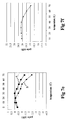
A first set of measures has been performed by using only one laser
diode, i.e. by using pump radiation at a single wavelength. Fig. 7a shows the
dependence of amplifier gain from temperature, when the temperature is
varied from 0°C to 65°C, using a pump wavelength of 974 nm at 25°C. The
gain values have been measured for a signal wavelength of 1552 nm,
approximately in the center of the considered wavelength band. As can be
observed in Fig. 7a, the difference between the peak and the minimum of the
curve (i.e. the maximum gain variation) is approximately 2 dB.
Other measures, whose results are shown in Fig. 7b and 7c, have been
performed with a single pump wavelength at 969 nm and 979 nm (at 25°C). In
these cases it has been found that the maximum variation of the amplifier gain
increases up to more than 3.5 dB.
Therefore, the pump absorption variation with temperature can be
reduced by choosing, among the manufactured 980 nm pump lasers, those
having at 32.5°C (i.e. in the middle of the considered temperature range) an
emission wavelength coinciding with the wavelength,of the peak of the curve
of absorption coefficient vs. emission wavelength (i.e. approximately 978 nm).
For those particular diodes, the working point moves almost symmetrically
along the said curve in the considered temperature range, and the variation of
the pump absorption can be as low as 2 dB. Nevertheless, the particular
choice of the pump laser is to be considered as a cost, since only a few of the
manufactured pump lasers have such an emission wavelength.
During the measures with a single pump wavelength, the Applicant has
also analyzed the dependence of the gain of the amplifier on the transmission
wavelength, and has verified that the flatness of the gain curve increases by
increasing the pump emission wavelength from 969 nm to 979 nm.
Further measures have been performed by using the double pump
scheme of Fig. 6.
Fig. 7d shows the results of measures performed by using two pump
wavelengths distant 10.5 nm, precisely λ1 = 971.5 nm and λ2 = 982 nm at
25°C. These wavelengths have been selected so as to have substantially the
same wavelength distance (Δλ/2) from λp at 32.5 °C. The resulting mixed
pumping radiation will then be referred to as "centered" with respect to the
cross-absorption vs. wavelength curve.
Fig. 7e shows the result of two sets of measures performed by using
two pump wavelengths distant 16.5 nm, in particular a first set of measures in
which λ1 = 970.5 nm and λ2 = 987 nm at 25°C (curve A), and a second set of
measures in which λ1 = 965.5 nm and λ2 = 982 nm at 25°C (curve B). In the
first case, the wavelengths have been selected with substantially the same
wavelength distance (Δλ/2) from 976 nm at 32.5°C. Differently from the
previous case, the Applicant has considered a wavelength equal to 976 nm
instead of λp for "centering" the mixed pumping radiation, so as to take into
account the asymmetry of the cross-absorption vs. wavelength curve.
Therefore, the mixed pump radiation resulting from λ1 = 970.5 nm and λ2 =
987 nm at 25°C will still referred to as "centered", although in this case the
reference wavelength is 976 nm, and the mixed pump radiation resulting from
λ1 = 965.5 nm and λ2 = 982 nm is "shifted" of -5 nm with respect to the
"centered" pump radiation, and it will be referred to as a "shifted" pump
radiation.
Fig. 7f shows the result of measures performed by using two pump
wavelengths distant 21.5 nm, precisely λ1 = 965.5 nm and λ2 = 987 nm. Again,
the wavelengths have been selected with substantially the same wavelength
distance (Δλ/2) from λp at 32.5 °C, and the resulting mixed pumping radiation
will be referred to as "centered" with respect to the cross-absorption vs.
wavelength curve.
In Figs. 7d and 7e, the gain curves have been normalized to the
respective peak values. The gain values have been measured for a signal
wavelength of 1552 nm.
It can be noticed that, when the wavelength distance Δλ between the
pump wavelengths increases, the gain shifts due to temperature variation
decrease. In particular, the maximum gain variation is approximately 2.3 dB
for the "centered" mixed pump radiation having Δλ=10.5 nm, 2.4 dB for the
"centered" mixed pump radiation having Δλ=16.5 nm, 1.4 dB for the "shifted"
mixed pump radiation having Δλ=16.5 nm, and 1.3 dB for the "centered" mixed
pump radiation having Δλ=21.5 nm. This trend has been verified for
wavelength distances Δλ up to 21.5 nm. For pump wavelength distances Δλ
greater than 21.5 nm, the gain shift due to temperature variations is expected
to increase again, due to the mechanism previously described. Therefore, a
pump wavelength distance Δλ=21.5 nm allows to minimize the gain shift due
to temperature variations.
The Applicant has verified that the curve of the gain of the amplifier vs.
transmission wavelength is more flat in the case of a double diode pump
scheme than in a single diode pump scheme.
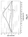
The Applicant has also determined the pump absorbed by the active
fiber by means of a numeric simulation of the system of Fig. 6. Fig. 8 shows
the result of the numeric simulation in the case of the single pump wavelength
λ = 976 nm at 25°C (curve A), of the "centered" mixed pump radiation having
Δλ=16.5 nm (curve B), and of the "centered" mixed pump radiation having
Δλ=21.5 nm (curve C). As can be derived from Fig. 8, the minimum variations
of pump absorption with temperature occurs in the case of the "centered"
mixed pump radiation having Δλ=21.5 nm.
In the case of the "centered" mixed pump radiation having Δλ=16.5 nm
(curve B), the pump absorption shows a decrease close to the extreme
temperatures 0°C and 65°C. This is due to the fact that λ2 becomes lower
than λp when the temperature decreases below a first limit between 0°C and
32.5°C, and λ1 becomes higher than λp when the temperature increases over
a second limit between 32.5°C and 65°C. When the temperature further
decreases or increases over these limits, the pump powers absorbed by the
active fiber from the first diode laser and from the second diode lasers
decrease substantially of the same quantity -ΔP, and the total pump power
absorption variation is therefore -2·ΔP.
During the above described measures, the Applicant has also analyzed
the dependence of the gain of the amplifier on the transmission wavelength,
and has verified that the two-wavelength pumping scheme allows to achieve a
greater flatness of the gain curve with respect to a single-wavelength pumping
scheme, and that a higher flatness is expected for a higher number of
appropriate pumping wavelengths.
Although the present invention has been described in terms of specific
exemplary embodiments, it will be appreciated that various modifications and
alterations might be made by those skilled in the art without departing from the
spirit and scope of the invention as set forth in the following claims.
In general, the mixed pump radiation can be fed to each active fiber of
the amplifier in a co-propagating direction, in a counter-propagating direction,
or bidirectionally.
The mixed pump radiation can include any number of wavelengths
mixed together. For example, three pump laser diodes can be used together
by a 3x3 coupler, so as to have a three-wavelength mixed pump radiation. In
this case, two wavelengths can be chosen lower than λp and one greater than
λp, or vice versa.
The different pump beams generating the mixed pump radiation can
also have different powers. In this case, the wavelength and the powers of
each pump beam will be chosen so as to balance the global effect due to
temperature variation. Moreover, couplers having coupling ratio different from
50/50 can be used.
The pumping arrangement of the present invention can also be applied
to integrated optics amplifiers as well.