EP1209557A2 - Multiple-drive library computer system - Google Patents
Multiple-drive library computer system Download PDFInfo
- Publication number
- EP1209557A2 EP1209557A2 EP02002783A EP02002783A EP1209557A2 EP 1209557 A2 EP1209557 A2 EP 1209557A2 EP 02002783 A EP02002783 A EP 02002783A EP 02002783 A EP02002783 A EP 02002783A EP 1209557 A2 EP1209557 A2 EP 1209557A2
- Authority
- EP
- European Patent Office
- Prior art keywords
- drive
- bus
- library
- drives
- host
- Prior art date
- Legal status (The legal status is an assumption and is not a legal conclusion. Google has not performed a legal analysis and makes no representation as to the accuracy of the status listed.)
- Withdrawn
Links
Images


Classifications
-
- G—PHYSICS
- G11—INFORMATION STORAGE
- G11B—INFORMATION STORAGE BASED ON RELATIVE MOVEMENT BETWEEN RECORD CARRIER AND TRANSDUCER
- G11B33/00—Constructional parts, details or accessories not provided for in the other groups of this subclass
- G11B33/12—Disposition of constructional parts in the apparatus, e.g. of power supply, of modules
- G11B33/125—Disposition of constructional parts in the apparatus, e.g. of power supply, of modules the apparatus comprising a plurality of recording/reproducing devices, e.g. modular arrangements, arrays of disc drives
- G11B33/127—Mounting arrangements of constructional parts onto a chassis
- G11B33/128—Mounting arrangements of constructional parts onto a chassis of the plurality of recording/reproducing devices, e.g. disk drives, onto a chassis
-
- G—PHYSICS
- G06—COMPUTING; CALCULATING OR COUNTING
- G06F—ELECTRIC DIGITAL DATA PROCESSING
- G06F13/00—Interconnection of, or transfer of information or other signals between, memories, input/output devices or central processing units
- G06F13/38—Information transfer, e.g. on bus
- G06F13/40—Bus structure
- G06F13/4063—Device-to-bus coupling
- G06F13/409—Mechanical coupling
-
- G—PHYSICS
- G11—INFORMATION STORAGE
- G11B—INFORMATION STORAGE BASED ON RELATIVE MOVEMENT BETWEEN RECORD CARRIER AND TRANSDUCER
- G11B33/00—Constructional parts, details or accessories not provided for in the other groups of this subclass
- G11B33/14—Reducing influence of physical parameters, e.g. temperature change, moisture, dust
- G11B33/1406—Reducing the influence of the temperature
- G11B33/1413—Reducing the influence of the temperature by fluid cooling
- G11B33/142—Reducing the influence of the temperature by fluid cooling by air cooling
Definitions
- This invention pertains to the repair of one or more failed storage drives in a multiple drive library computer system. Repair of a failed drive occurs while one or more good drives in the library system remain online. In this manner, a host may have continual and uninterrupted access to information stored within the library.
- the first component to fail due to excessive use is often a storage drive.
- a storage drive fails, the library undergoes a period of down time while the drive is repaired and/or replaced. During this down time, a host (whether it be a UNIX work station, PC network server or otherwise) cannot access any of the information contained within the library.
- the RAID technology involves a method of reconstructing data which is lost in the event of a drive's failure.
- Data is stored in a redundant array of non-removable media type drives, such that when a failed drive is replaced, an error-correction operation can be applied to the data blocks of the remaining storage drives in the redundant array so that the data which was lost can be reconstructed.
- the RAID method helps to minimize library down time, the method is not applicable to removable media type libraries. In a removable media type library, failure of a drive does not result in loss of data. It only results in loss of access to data.
- a hot repairable system storage drives are guided on rails into hot repair sockets.
- a failed drive may be removed from its socket without notification to the library system or a host.
- a system of long and short pins is used to incrementally disconnect power to the drive, to notify the library system and the host that the drive is no longer available, and to make the necessary changes in system parameters to keep the library system online.
- there is a barrier to implementing hot repair technology in a removable media type library The barrier exists due to the requirement of a removable media type library that the media inserting faces of its storage drives face a robotic media inserter. In order to keep such a system online, it is necessary to remove storage drives by pulling them away from the robotic inserter.
- the electrical connection faces of the storage drives (which in standard drives are opposite their media inserting faces) must be free of blockage (sockets, circuit boards, pins, etc.).
- a storage drive would need to be constructed wherein its media inserting face and electrical connection face were on adjacent sides, rather than on opposite sides. This is an added expense which is unnecessary in view of the online repairable system and method of online drive repair disclosed herein.
- an online repairable multiple drive library computer system comprising a plurality of storage drives.
- the drives are connected to a primary I/O bus via a plurality of secondary I/O buses which are pigtailed to the primary I/O bus.
- the primary I/O bus is connected to a library controller.
- the I/O buses generally operate under a SCSI protocol.
- the library controller communicates with a host system via the primary and secondary I/O buses.
- the controller communicates with the drives via an internal general purpose bus running between the controller and each of the storage drives.
- the inventors have also devised a method of online drive repair which comprises the steps of detecting that a drive has failed, placing the failed drive in an offline state, removing power to the failed drive, disconnecting any cabling attached to the failed drive, replacing the failed drive, reconnecting cabling to the replaced drive, restoring power to the replaced drive, and placing the replaced drive in an online state.
- the above system and method allow good drives in a multiple drive library computer system to remain online, and accessible to a host, during the repair of one or more failed drives.
- Library down time is thereby significantly reduced, or in the case of a removable media type library, library down time is eliminated.
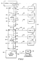
- a multiple drive library computer system 44 is pictured in FIGS. 1, 2 & 4, which may generally comprise an I/O bus 122, generally operating under a SCSI protocol, said bus 122 comprising a primary I/O bus 94 and a plurality of secondary I/O buses 96, 98, 100, 102, 104, 106, pigtailed to said primary bus 94, a plurality of storage drives 50, 52, 54, 56, 58, 60 connected to said plurality of secondary I/O buses (96, 98...), and a library controller 36, connected to said primary I/O bus 94, said controller 36 comprising firmware to communicate with a host computer 48 via said I/O bus 122, and firmware to communicate with said storage drives (50, 52%) via a general purpose bus 62.
- I/O bus 122 generally operating under a SCSI protocol
- said bus 122 comprising a primary I/O bus 94 and a plurality of secondary I/O buses 96, 98, 100, 102, 104, 106
- the library system 44 comprises six computer storage drives (50, 52).
- the storage drives are housed in six modular housings 20, 22, 24, 26, 28, 30, each of which can hold one full-height drive (50, 52).
- the drives (50, 52%) are connected to other library system components via an internal I/O bus 122.
- This bus 122 generally operates under a Small Computer Systems Interface protocol (SCSI protocol). See FIG. 2.
- the internal I/O bus 122 further comprises a primary I/O bus 94, and a plurality of secondary I/O buses (96, 98%), pigtailed to said primary I/O bus 94. All storage drives (50, 52%) are connected to the I/O bus 122 via the secondary (pigtailed) buses (96, 98).
- the primary I/O bus 94 is shown running between connectors 78, 80, 82, 84, 86, 88 on upper 32 and lower 34 interposer PC boards. Some sections of the primary I/O bus 94 may comprise traces 112, 114, 118, 120 etched into the interposer boards 32, 34. Other sections 108, 110, 116 of the primary I/O bus 94 may comprise standard SCSI cabling.
- a general purpose bus 62 is connected between the storage drives (50, 52%) and the library controller 36. While the primary function of the SCSI protocol I/O bus 122 is data transfer, the primary function of the general purpose bus is communication between the storage drives (50, 52%) and the library controller 36.
- FIG. 4 shows the rear face of a storage drive 60.
- the storage drives (50, 52%) shown are optical, removable media type drives. See. FIG. 5.
- Each drive (50, 52%) has a media inserting face 300 abutting a robotic media inserter 40.
- the media inserting face 300 of a drive 60 is shown in FIG. 5.
- a typical placement of a robotic media inserter 40 is best seen in FIG. 4.
- Robotic media inserters for optical, removable media type drives are disclosed in U.S. patent #5,010,536 and U.S. patent application serial #08/296,069 filed August 24, 1994, which are hereby specifically incorporated by reference.
- Opposite said media inserting faces 300, the drives (50, 52...) have electrical connection faces 302.
- Each electrical connection face 302 has a connector (e.g. connector 304 on drive 60 as shown in FIG. 4) for connecting a secondary I/O bus (96, 98...) and a connector to which a power cable may be attached (not shown).
- the primary I/O bus 94 is attached to a library controller 36 (or autochanger controller) at connector 76.
- a general purpose bus 62 is also attached to the controller.
- the controller 36 comprises firmware which allows it to communicate with the storage drives (50, 52%) via the general purpose bus 62.
- the controller 36 also comprises firmware which allows it to communicate with a host 48 (whether it be a UNIX work station, PC network server or otherwise) via the SCSI protocol I/O bus 122.
- the controller 36 is responsive to host commands and may perform such operations as keeping track of the location of removable media cartridges, moving removable media cartridges, and relaying its successes and/or failures to the host 48.
- the controller 36 may also process and carry out library commands.
- the controller 36 may also be responsible for changing drive states, in the preferred embodiment, this is left to the host 48.
- the controller 36 contains a microprocessor, the controller is a component which may only speak when spoken to - it cannot initiate action.
- the controller 36 may also comprise firmware which allows it to enable or disable power to one or more storage drives (50, 52). In so enabling or disabling power, a system for suppressing power transients is used. This power transient suppression system is similar to that disclosed in U.S. patent application serial #08/331,468 filed October 31, 1994, which is hereby specifically incorporated by reference. Alternatively, switches (not shown) could be used to enable or disable power to the drives (50, 52).
- An LED 64, 66, 68, 70, 72, 74 is mounted next to each drive (50, 52).
- the LEDs (64, 66%) are mounted on the interposer boards 32, 34.
- the LEDs (64, 66%) may be controlled by either the library system 44 or the host 48 to serve as a visual indication of the status of a drive (50, 52%) to a service technician.
- a lighted LED (64, 66%) could signify "power on”
- an unlighted LED (64, 66%) could signify “power off”
- a flashing LED (64, 66%) could signify a powered drive in an "Offline_failed" state (this state will soon be described in more detail).
- a SCSI repeater board 46 is also connected to the primary I/O bus 94 via connector 90. See FIG. 2.
- the repeater board 46 is contained within repeater board enclosure 38.
- the repeater board 46 is responsible for electrically isolating I/O bus 122 from the outside world. It protects the protocol used on bus 122 from being reconfigured by a component outside the library system 44, such as the host 48.
- the repeater board 46 provides an input 128 for an external SCSI bus 92 which connects the library system 44 to a host 48.
- the host 48 may be a UNIX work station, PC network server, or other host device as previously mentioned.
- the repeater board 46 is especially important in the library system 44 outlined above due to the configuration of the I/O bus 122.
- a typical SCSI system comprises several components which are daisy-chained together. Thus, removing one component from the system causes a break in the bus which can shut down communication with many components. Since a purpose of this invention was to achieve an online repairable system, it became necessary to construct a cable which allowed for removal of a single component without disabling the entire bus. To achieve the desired result, storage drives (50, 527) are pigtailed to a primary I/O bus 94 via secondary I/O buses (96, 98).
- any secondary I/O bus (96, 98%) may be removed from the system without breaking the primary I/O bus 94 and interfering with communication between other system components via the primary I/O bus 94.
- SCSI protocol dictates that a bus 122 may comprise no more than six feet of cable, and a stub (such as pigtails 96, 98...) off of a primary bus 94 may be no longer than 100mm.
- the primary bus 94 comprises approximately 62" of cable, and each pigtail (96, 987) comprises approximately 12" of cable.
- the total cable length is 11'2".
- the I/O bus 122 must be isolated from the outside world, and cannot be subject to reconfiguration.
- the repeater board 46 serves this important function.
- the storage drives (50, 52%) are mounted to the library system frame structure 42 via modular drive housings (20, 22).
- the drives (50, 52%) could be individually mounted directly to the library system frame structure 42.
- this arrangement is not preferred due to the greater difficulty in accessing drives (50, 52%) while keeping the library system 44 online.
- FIG. 5 shows a modular drive housing 30 removed from the library system 44.
- Each modular drive housing (20, 227) comprises its own cooling fan 310, 312, 314, 316, 318 & 320, and a handle 330, 332, 334, 336, 338 & 340 for removing it from the library system 44. See also, FIG. 4.
- Removal of a modular drive housing (20, 22%) is accomplished by first disconnecting any cabling extending from said modular housing (20, 22%) (such as I/O bus cables (96, 98%) and any power cables (not shown)). Since the electrical connection faces 302 of the drives (50, 52%) are not readily accessible while the drives (50, 52%) are mounted within a modular housing (20, 22%), cabling is disconnected at the interposer boards 32 & 34. As a consequence, secondary I/O buses (96, 98%) and portions of power cables will be removed with a modular housing (20, 22). Once cabling is disconnected, a modular housing 30 may be removed from the library system 44. Cabling is not shown in FIG. 5 so as not to interfere with a view of cooling fan 320 and handle 340.
- a modular housing (20, 22%) is removed by pulling the modular housing (20, 22%) away from the robotic media inserter 40. Handles (330, 332%) on the modular housings (20, 22%) facilitate their removal. By way of example, a modular housing 30, and the drive 60 mounted therein, are removed from the library system 44 as a unit in FIG. 5.
- the library system 44 comprises twelve computer storage drives 150, 151, 152, 153, 154, 155, 156, 157, 158, 159, 160, 161.
- the twelve storage drives (150, 151%) are housed in the same six modular housings (20, 22%) identified above.
- Each modular housing (20, 22%) is designed so that it may, without any modification, hold either one full-height drive (50, 52%) or two half-height drives (150, 151).
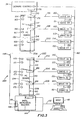
- the drives (150, 151%) are connected to other system components via two internal I/O buses 222, 223.
- Each bus 222, 223 generally operates under a SCSI protocol. See FIG. 3.
- Two internal I/O buses 222, 223 are required in the twelve drive embodiment due to the SCSI limitation of eight component addresses on any particular bus.
- the first SCSI I/O bus 123 comprises a primary bus 194 which includes several cable sections 208, 210, 212, 214 running between numerous connectors 176, 178, 180, 182, 191, and secondary buses 196, 198, 200.
- the second SCSI I/O bus 122 comprises a primary bus 195 which again includes several cable sections 209, 213, 215 running between numerous connectors 184, 186, 188, 190, and secondary buses 202, 204, 206.
- Six of the twelve drives 150, 152, 154, 156, 158, 160 are connected directly to secondary buses 196, 198, 200, 202, 204, 206.
- the remaining six drives 151, 153, 155, 157, 159, 161 are connected to the SCSI I/O buses 222, 223 via the first six drives 150, 152, 154, 156, 158, 160 by way of several daisy-chained I/O buses 197, 199, 201, 203, 205, 207.
- a general purposes bus 162 runs between the storage drives (150, 151%) and the library controller 36.
- Upper 132 and lower 134 PC interposer boards again provide mounts for bus connectors 178, 180, 182, 184, 186, 188 and power status LEDs 164-175.
- SCSI I/O buses 222, 223 Due to the presence of two SCSI I/O buses 222, 223, two SCSI repeater boards are required 144, 146, one for each SCSI bus section.
- the host 48 is connected to each of the repeater boards 144, 146 via a SCSI compatible cable.
- FIG. 6 shows a rear view of the modular housing 30 of FIG. 5, wherein two half-height drives 160, 161 have been substituted for the one full-height drive 60.
- the media inserting faces 340 of the two half-height drives 160, 161 are seen extending from the rear of the housing 30.
- FIG. 7 shows a front perspective view of the components of FIG. 6.
- FIG. 8 shows the two half-height drives 160, 161 and modular housing 30 of FIG. 6 in a disassembled fashion.
- the secondary I/O bus 206 and daisy-chained I/O bus 207 which connect the storage drives shown 160, 161 to the primary I/O bus 195 are also shown in FIG. 8.
- FIG. 8 reveals the three subsections 31, 33 & 35 which make up a modular housing 30.
- the failure of a drive must be detected or instructed.
- the host's software provides the means for detecting when a drive 160 has failed.
- the host 48 may detect that a drive 160 has failed by several avenues. If the host 48 issues a command to the library to eject or load media to a drive 160 and receives a status code back from the library controller 36 indicating that the move operation was unsuccessful, the host 48 may assume that the drive 160 was at fault and is in need or repair.
- the host 48 may also detect drive failure from a system level error indicating that the drive 160 is not functioning correctly.
- the host 48 attempts to remove media from the failed drive, if any is present. After removing media, the host 48 informs the library controller 36 of the drive failure, and places the drive 160 in an "Offline_failed" state. (Note: a description of all of the various drive states is found in FIG. 10) The library controller 36 will store the drive state information, and will not allow further access to the failed drive 160 until its state is changed to "Online_good”. Drive states remain through power cycling.
- the failed drive 160 may be serviced while the library system 44 remains online. It is therefore possible for the host 48 to continue accessing one or more good drives 150, 151, 152, 153, 154, 155, 156, 157, 158, 159 in an "Online_good” state, and retrieve information from media inserted into those drives, while the failed drive 160 is being repaired.
- a qualified service person accesses the internal workings of the library (shown in FIG. 1).
- the service person will know which drive is in an "Offline_failed" state by a flashing LED 174 near the drive 160. If, as assumed, a failed drive is mounted in a modular housing 30 containing two half-height drives 160, 161, both drives 160, 161 will need to be taken offline. However, only the failed drive 160 will actually be replaced.
- the host 48 will place the good drive 161 which is commonly housed with the failed drive 160 in an "Offline_good_pending" state. The host 48 can then remove media from the commonly housed good drive 161 before placing it in an "Offline_good” state.
- the library controller 36 With both drives 160, 161 in a drive pair offline, the library controller 36 will remove power to the drive pair. LEDs 174, 175 for the drive pair 160, 161 will indicate that power to the drives 160, 161 has been removed. At this point, the secondary I/O bus cable 206 may be safely disconnected from the primary I/O bus 195. Power cables to the drives (not shown) may also be disconnected at the PC interposer board 134 corresponding to the drives 160, 161 to be removed. In this manner, no interruption to the rest of the system 44 or the host 48 will occur.
- the modular housing 30 containing the failed drive 160 may now be removed.
- the modular housing 30 is removed by pulling it away from the robotic media inserter 40.
- the robotic media inserter 40 is not interrupted as it continues to feed media to the library's good drives 150, 151, 152, 153, 154, 155, 156, 157, 158, 159.
- the removed modular housing 30 is again mounted in its place, and cabling is reconnected to the removed drives 160, 161, the service technician sets the drive pair status to "Online_pending" via a switch (not shown) on the corresponding PC interposer board 134 which alerts the library controller 36.
- the library controller 36 will then apply power to the drive pair 160, 161, and will also inform the host 48 of the drive state changes.
- the host 48 then changes the states of the "Online_pending" drives to "Online_good”. All of the library's drives (150, 151%) are now accessible to the host 48.
- the host 48 may only access a drive (150, 151%) when it is in an "Online_good” or “Offline_good_pending” state. At all other times, the library controller 36 will deny access to a drive (150, 151).
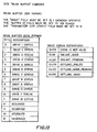
- the host 48 changes drive states for the drives (150, 151%) via a SCSI "Write Buffer” command. Whenever the host 48 wants to change the state of a drive, it will simply issue the appropriate "Write Buffer” command. See FIG. 11 for specifications of the SCSI "Write Buffer” command.
- the library controller 36 communicates to the host 48 via the SCSI "Unit Attention” condition. Whenever the library controller 36 wants to inform the host 48 of a change in the state(s) of the drive(s), it issues a "Unit Attention” condition on the next SCSI command sent by the host 48. Upon receiving the "Unit Attention” condition, the host 48 will send a SCSI "Read Buffer” command to determine the state change(s) of the drive(s). See FIG. 12 for specifications of the SCSI "Read Buffer” command.
- the library controller 36 will respond with a "Unit Attention” condition to any command from the host 48 (except Inquiry) when there is a pending state change for one or more of the library's storage drives (150, 151).
- the host 48 must then send a "Read Buffer” command to determine the state change.
- the "Unit Attention” condition will only be reported once per state change.
- the host 48 may poll the library controller 36 with the "Read Buffer” command, if desired.
- the library controller 36 will respond with an "Illegal Request” condition to any Move or Exchange command from the host 48 that involves a drive that is not in an "Online_good” or “Offline_good_pending” state.
Abstract
Description
- This invention pertains to the repair of one or more failed storage drives in a multiple drive library computer system. Repair of a failed drive occurs while one or more good drives in the library system remain online. In this manner, a host may have continual and uninterrupted access to information stored within the library.
- Although the online repairable system, components thereof (namely an I/O Bus and a Computer Frame Structure with Modular Housings, both on which U.S. patent applications were filed concurrently with this application on July 31, 1995, which applications are hereby incorporated by reference), and method of online drive repair disclosed herein are especially advantageous in removable media type multiple drive library computer systems, they may also be adapted to other multiple component computer systems as well.
- In a multiple drive library computer system, the first component to fail due to excessive use is often a storage drive. Typically, when a storage drive fails, the library undergoes a period of down time while the drive is repaired and/or replaced. During this down time, a host (whether it be a UNIX work station, PC network server or otherwise) cannot access any of the information contained within the library.
- Since loss of information access is unacceptable, efforts have been made to minimize library down time. These efforts include Redundant Array of Inexpensive Disks (RAID) and hot repair technologies.
- The RAID technology involves a method of reconstructing data which is lost in the event of a drive's failure. Data is stored in a redundant array of non-removable media type drives, such that when a failed drive is replaced, an error-correction operation can be applied to the data blocks of the remaining storage drives in the redundant array so that the data which was lost can be reconstructed. Although the RAID method helps to minimize library down time, the method is not applicable to removable media type libraries. In a removable media type library, failure of a drive does not result in loss of data. It only results in loss of access to data.
- In a hot repairable system, storage drives are guided on rails into hot repair sockets. A failed drive may be removed from its socket without notification to the library system or a host. As the failed drive is pulled from its socket, a system of long and short pins is used to incrementally disconnect power to the drive, to notify the library system and the host that the drive is no longer available, and to make the necessary changes in system parameters to keep the library system online. However, there is a barrier to implementing hot repair technology in a removable media type library. The barrier exists due to the requirement of a removable media type library that the media inserting faces of its storage drives face a robotic media inserter. In order to keep such a system online, it is necessary to remove storage drives by pulling them away from the robotic inserter. To do this, the electrical connection faces of the storage drives (which in standard drives are opposite their media inserting faces) must be free of blockage (sockets, circuit boards, pins, etc.). To affect a hot repair of a removable media storage drive, a storage drive would need to be constructed wherein its media inserting face and electrical connection face were on adjacent sides, rather than on opposite sides. This is an added expense which is unnecessary in view of the online repairable system and method of online drive repair disclosed herein.
- It is therefore a primary object of this invention to significantly reduce the down time of a multiple drive library computer system upon failure of one or more of the library's storage drives. In the case of a removable media type library, it is believed that library down time can be eliminated.
- It is a further object of this invention to allow a host to have continual access to one or more good storage drives of a multiple drive library computer system while one or more failed drives of the library are repaired.
- In the achievement of the foregoing objects, the inventors have devised an online repairable multiple drive library computer system comprising a plurality of storage drives. The drives are connected to a primary I/O bus via a plurality of secondary I/O buses which are pigtailed to the primary I/O bus. The primary I/O bus is connected to a library controller. The I/O buses generally operate under a SCSI protocol. The library controller communicates with a host system via the primary and secondary I/O buses. The controller communicates with the drives via an internal general purpose bus running between the controller and each of the storage drives.
- The inventors have also devised a method of online drive repair which comprises the steps of detecting that a drive has failed, placing the failed drive in an offline state, removing power to the failed drive, disconnecting any cabling attached to the failed drive, replacing the failed drive, reconnecting cabling to the replaced drive, restoring power to the replaced drive, and placing the replaced drive in an online state. -
- The above system and method allow good drives in a multiple drive library computer system to remain online, and accessible to a host, during the repair of one or more failed drives.
- Library down time is thereby significantly reduced, or in the case of a removable media type library, library down time is eliminated.
- These and other important advantages and objectives of the present invention will be further explained in, or will become apparent from, the accompanying description, drawing and claims.
- An illustrative and presently preferred embodiment of the invention is illustrated in the drawing in which:
- FIG. 1 is a perspective view showing a multiple drive library computer system;
- FIG. 2 is a diagrammatic view showing the six drives of FIG. 1 connected to other library system components via an I/O bus;
- FIG. 3 is a diagrammatic view showing a variation on the system of FIG. 1 which includes twelve drives;
- FIG. 4 is an enhanced version of FIG. 1, wherein the I/O bus of FIG. 2 has been added to the figure, one of the modular drive housings has been removed to show the details of the drive/bus connections, and the library's frame structure has been removed to reveal the system's robotic media inserter;
- FIG. 5 is a rear perspective view of one of the modular drive housings shown in FIG. 1, wherein one full-height drive is mounted therein;
- FIG. 6 is a rear perspective view of the modular drive housing of FIG. 5, wherein two half-height drives are now mounted therein;
- FIG. 7 is a front perspective view of the modular drive housing and drives of FIG. 6;
- FIG. 8 is a rear perspective view of the disassembled parts of FIG. 6, wherein I/O buses have been added;
- FIG. 9 is a flow chart of the steps involved in the method of online drive repair disclosed herein;
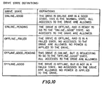
- FIG. 10 is a table of the drive state definitions used in the method of online drive repair disclosed herein;
- FIG. 11 gives the specifications of the SCSI "Write Buffer" command used by a host computer in accomplishing the method of online drive repair disclosed herein; and
- FIG. 12 gives the specifications of the SCSI "Read Buffer" command used by a host computer in accomplishing the method of online drive repair disclosed herein.
-
- A multiple drive
library computer system 44 is pictured in FIGS. 1, 2 & 4, which may generally comprise an I/O bus 122, generally operating under a SCSI protocol, saidbus 122 comprising a primary I/O bus 94 and a plurality of secondary I/O buses primary bus 94, a plurality ofstorage drives library controller 36, connected to said primary I/O bus 94, saidcontroller 36 comprising firmware to communicate with ahost computer 48 via said I/O bus 122, and firmware to communicate with said storage drives (50, 52...) via ageneral purpose bus 62. - Having thus described the multiple drive library computer system in general, the system will now be described in further detail.
- In a first preferred embodiment, the
library system 44 comprises six computer storage drives (50, 52...). The storage drives are housed in sixmodular housings - The drives (50, 52...) are connected to other library system components via an internal I/
O bus 122. Thisbus 122 generally operates under a Small Computer Systems Interface protocol (SCSI protocol). See FIG. 2. The internal I/O bus 122 further comprises a primary I/O bus 94, and a plurality of secondary I/O buses (96, 98...), pigtailed to said primary I/O bus 94. All storage drives (50, 52...) are connected to the I/O bus 122 via the secondary (pigtailed) buses (96, 98...). - In FIG. 2, the primary I/
O bus 94 is shown running betweenconnectors O bus 94 may comprisetraces interposer boards Other sections O bus 94 may comprise standard SCSI cabling. - A
general purpose bus 62 is connected between the storage drives (50, 52...) and thelibrary controller 36. While the primary function of the SCSI protocol I/O bus 122 is data transfer, the primary function of the general purpose bus is communication between the storage drives (50, 52...) and thelibrary controller 36. - FIG. 4 shows the rear face of a
storage drive 60. The storage drives (50, 52...) shown are optical, removable media type drives. See. FIG. 5. Each drive (50, 52...) has amedia inserting face 300 abutting arobotic media inserter 40. Themedia inserting face 300 of adrive 60 is shown in FIG. 5. A typical placement of arobotic media inserter 40 is best seen in FIG. 4. Robotic media inserters for optical, removable media type drives are disclosed in U.S. patent #5,010,536 and U.S. patent application serial #08/296,069 filed August 24, 1994, which are hereby specifically incorporated by reference. Opposite said media inserting faces 300, the drives (50, 52...) have electrical connection faces 302. Eachelectrical connection face 302 has a connector (e.g. connector 304 ondrive 60 as shown in FIG. 4) for connecting a secondary I/O bus (96, 98...) and a connector to which a power cable may be attached (not shown). - The primary I/
O bus 94 is attached to a library controller 36 (or autochanger controller) atconnector 76. As earlier mentioned, ageneral purpose bus 62 is also attached to the controller. Thecontroller 36 comprises firmware which allows it to communicate with the storage drives (50, 52...) via thegeneral purpose bus 62. Thecontroller 36 also comprises firmware which allows it to communicate with a host 48 (whether it be a UNIX work station, PC network server or otherwise) via the SCSI protocol I/O bus 122. - The
controller 36 is responsive to host commands and may perform such operations as keeping track of the location of removable media cartridges, moving removable media cartridges, and relaying its successes and/or failures to thehost 48. Thecontroller 36 may also process and carry out library commands. Although thecontroller 36 may also be responsible for changing drive states, in the preferred embodiment, this is left to thehost 48. Although thecontroller 36 contains a microprocessor, the controller is a component which may only speak when spoken to - it cannot initiate action. - The
controller 36 may also comprise firmware which allows it to enable or disable power to one or more storage drives (50, 52...). In so enabling or disabling power, a system for suppressing power transients is used. This power transient suppression system is similar to that disclosed in U.S. patent application serial #08/331,468 filed October 31, 1994, which is hereby specifically incorporated by reference. Alternatively, switches (not shown) could be used to enable or disable power to the drives (50, 52...). - An
LED interposer boards library system 44 or thehost 48 to serve as a visual indication of the status of a drive (50, 52...) to a service technician. For example, a lighted LED (64, 66...) could signify "power on", an unlighted LED (64, 66...) could signify "power off", and a flashing LED (64, 66...) could signify a powered drive in an "Offline_failed" state (this state will soon be described in more detail). - A
SCSI repeater board 46 is also connected to the primary I/O bus 94 viaconnector 90. See FIG. 2. Therepeater board 46 is contained withinrepeater board enclosure 38. Therepeater board 46 is responsible for electrically isolating I/O bus 122 from the outside world. It protects the protocol used onbus 122 from being reconfigured by a component outside thelibrary system 44, such as thehost 48. Therepeater board 46 provides aninput 128 for anexternal SCSI bus 92 which connects thelibrary system 44 to ahost 48. Thehost 48 may be a UNIX work station, PC network server, or other host device as previously mentioned. - The
repeater board 46 is especially important in thelibrary system 44 outlined above due to the configuration of the I/O bus 122. A typical SCSI system comprises several components which are daisy-chained together. Thus, removing one component from the system causes a break in the bus which can shut down communication with many components. Since a purpose of this invention was to achieve an online repairable system, it became necessary to construct a cable which allowed for removal of a single component without disabling the entire bus. To achieve the desired result, storage drives (50, 52...) are pigtailed to a primary I/O bus 94 via secondary I/O buses (96, 98...). Any secondary I/O bus (96, 98...) may be removed from the system without breaking the primary I/O bus 94 and interfering with communication between other system components via the primary I/O bus 94. However, SCSI protocol dictates that abus 122 may comprise no more than six feet of cable, and a stub (such aspigtails primary bus 94 may be no longer than 100mm. In the preferred embodiment described above, theprimary bus 94 comprises approximately 62" of cable, and each pigtail (96, 98...) comprises approximately 12" of cable. The total cable length is 11'2". In order to successfully use a SCSI protocol on this newly invented bus cable, the I/O bus 122 must be isolated from the outside world, and cannot be subject to reconfiguration. Therepeater board 46 serves this important function. - The storage drives (50, 52...) are mounted to the library
system frame structure 42 via modular drive housings (20, 22...). In an alternative embodiment (not shown), the drives (50, 52...) could be individually mounted directly to the librarysystem frame structure 42. However, this arrangement is not preferred due to the greater difficulty in accessing drives (50, 52...) while keeping thelibrary system 44 online. - FIG. 5 shows a
modular drive housing 30 removed from thelibrary system 44. Each modular drive housing (20, 22...) comprises itsown cooling fan handle library system 44. See also, FIG. 4. - Removal of a modular drive housing (20, 22...) is accomplished by first disconnecting any cabling extending from said modular housing (20, 22...) (such as I/O bus cables (96, 98...) and any power cables (not shown)). Since the electrical connection faces 302 of the drives (50, 52...) are not readily accessible while the drives (50, 52...) are mounted within a modular housing (20, 22...), cabling is disconnected at the
interposer boards 32 & 34. As a consequence, secondary I/O buses (96, 98...) and portions of power cables will be removed with a modular housing (20, 22...). Once cabling is disconnected, amodular housing 30 may be removed from thelibrary system 44. Cabling is not shown in FIG. 5 so as not to interfere with a view of coolingfan 320 and handle 340. A modular housing (20, 22...) is removed by pulling the modular housing (20, 22...) away from therobotic media inserter 40. Handles (330, 332...) on the modular housings (20, 22...) facilitate their removal. By way of example, amodular housing 30, and thedrive 60 mounted therein, are removed from thelibrary system 44 as a unit in FIG. 5. - In a second preferred embodiment, the
library system 44 comprises twelve computer storage drives 150, 151, 152, 153, 154, 155, 156, 157, 158, 159, 160, 161. The twelve storage drives (150, 151...) are housed in the same six modular housings (20, 22...) identified above. Each modular housing (20, 22...) is designed so that it may, without any modification, hold either one full-height drive (50, 52...) or two half-height drives (150, 151...). - The drives (150, 151...) are connected to other system components via two internal I/
O buses bus O buses primary bus 194 which includesseveral cable sections numerous connectors secondary buses O bus 122 comprises aprimary bus 195 which again includesseveral cable sections numerous connectors secondary buses drives secondary buses drives O buses drives O buses - As in the first embodiment, a
general purposes bus 162 runs between the storage drives (150, 151...) and thelibrary controller 36.Upper 132 and lower 134 PC interposer boards again provide mounts forbus connectors - Due to the presence of two SCSI I/
O buses host 48 is connected to each of therepeater boards - FIG. 6 shows a rear view of the
modular housing 30 of FIG. 5, wherein two half-height drives 160, 161 have been substituted for the one full-height drive 60. Themedia inserting faces 340 of the two half-height drives 160, 161 are seen extending from the rear of thehousing 30. FIG. 7 shows a front perspective view of the components of FIG. 6. FIG. 8 shows the two half-height drives 160, 161 andmodular housing 30 of FIG. 6 in a disassembled fashion. The secondary I/O bus 206 and daisy-chained I/O bus 207 which connect the storage drives shown 160, 161 to the primary I/O bus 195 are also shown in FIG. 8. As previously stated, these I/O buses modular housing 30 as a unit. In this embodiment, the secondary I/O buses (196, 198...) are approximately fourteen inches in length. Finally, FIG. 8 reveals the threesubsections modular housing 30. - Our method of repairing one or more drives in the multiple drive library computer systems described above is as follows. For purposes of this description, it will be assumed that the failed drive is a half-
height drive 160 housed as a pair with another half-height drive 161 in a singularmodular housing 30 contained within a system similar to that described in the second preferred embodiment described above. However, it is important to keep in mind that this method is also applicable to the repair of a full-height drive, or a drive in a library system wherein more than two drives are mounted within a singularmodular housing 30. The method is also applicable to the repair of two or more drives at the same time. - First, the failure of a drive must be detected or instructed. Refer to the flow chart in FIG. 9. This may be done by either the
library controller 36 and/or thehost 48. In the preferred method, the host's software provides the means for detecting when adrive 160 has failed. Thehost 48 may detect that adrive 160 has failed by several avenues. If thehost 48 issues a command to the library to eject or load media to adrive 160 and receives a status code back from thelibrary controller 36 indicating that the move operation was unsuccessful, thehost 48 may assume that thedrive 160 was at fault and is in need or repair. Thehost 48 may also detect drive failure from a system level error indicating that thedrive 160 is not functioning correctly. - Once a drive's failure is detected, the
host 48 attempts to remove media from the failed drive, if any is present. After removing media, thehost 48 informs thelibrary controller 36 of the drive failure, and places thedrive 160 in an "Offline_failed" state. (Note: a description of all of the various drive states is found in FIG. 10) Thelibrary controller 36 will store the drive state information, and will not allow further access to the faileddrive 160 until its state is changed to "Online_good". Drive states remain through power cycling. - The failed
drive 160 may be serviced while thelibrary system 44 remains online. It is therefore possible for thehost 48 to continue accessing one or moregood drives drive 160 is being repaired. - While the
library system 44 remains operational, a qualified service person accesses the internal workings of the library (shown in FIG. 1). The service person will know which drive is in an "Offline_failed" state by a flashingLED 174 near thedrive 160. If, as assumed, a failed drive is mounted in amodular housing 30 containing two half-height drives 160, 161, bothdrives drive 160 will actually be replaced. - In the preferred embodiment, the
host 48 will place thegood drive 161 which is commonly housed with the faileddrive 160 in an "Offline_good_pending" state. Thehost 48 can then remove media from the commonly housedgood drive 161 before placing it in an "Offline_good" state. - With both
drives library controller 36 will remove power to the drive pair.LEDs 174, 175 for thedrive pair drives O bus cable 206 may be safely disconnected from the primary I/O bus 195. Power cables to the drives (not shown) may also be disconnected at thePC interposer board 134 corresponding to thedrives system 44 or thehost 48 will occur. - The
modular housing 30 containing the faileddrive 160 may now be removed. Themodular housing 30 is removed by pulling it away from therobotic media inserter 40. By removing thedrives robotic media inserter 40 is not interrupted as it continues to feed media to the library'sgood drives - After the failed
drive 160 is replaced, the removedmodular housing 30 is again mounted in its place, and cabling is reconnected to the removed drives 160, 161, the service technician sets the drive pair status to "Online_pending" via a switch (not shown) on the correspondingPC interposer board 134 which alerts thelibrary controller 36. Thelibrary controller 36 will then apply power to thedrive pair host 48 of the drive state changes. Thehost 48 then changes the states of the "Online_pending" drives to "Online_good". All of the library's drives (150, 151...) are now accessible to thehost 48. - The
host 48 may only access a drive (150, 151...) when it is in an "Online_good" or "Offline_good_pending" state. At all other times, thelibrary controller 36 will deny access to a drive (150, 151...). - The
host 48 changes drive states for the drives (150, 151...) via a SCSI "Write Buffer" command. Whenever thehost 48 wants to change the state of a drive, it will simply issue the appropriate "Write Buffer" command. See FIG. 11 for specifications of the SCSI "Write Buffer" command. - The
library controller 36 communicates to thehost 48 via the SCSI "Unit Attention" condition. Whenever thelibrary controller 36 wants to inform thehost 48 of a change in the state(s) of the drive(s), it issues a "Unit Attention" condition on the next SCSI command sent by thehost 48. Upon receiving the "Unit Attention" condition, thehost 48 will send a SCSI "Read Buffer" command to determine the state change(s) of the drive(s). See FIG. 12 for specifications of the SCSI "Read Buffer" command. Specifications for the "Unit Attention" condition are as follows:"Request Sense" data for the SCSI "Unit Attention" Condition: Sense Key = 6 (Unit Attention) ASC = 0x2A (Parameters Changed) ASCQ = 0x80 (Vendor Unique for HP Libraries) - The
library controller 36 will respond with a "Unit Attention" condition to any command from the host 48 (except Inquiry) when there is a pending state change for one or more of the library's storage drives (150, 151...). Thehost 48 must then send a "Read Buffer" command to determine the state change. The "Unit Attention" condition will only be reported once per state change. Thehost 48 may poll thelibrary controller 36 with the "Read Buffer" command, if desired. - The
library controller 36 will respond with an "Illegal Request" condition to any Move or Exchange command from thehost 48 that involves a drive that is not in an "Online_good" or "Offline_good_pending" state. The specifications for the SCSI "Illegal Request" Condition are given below:"Request Sense" data for the SCSI "Illegal Request" condition: Sense Key = 5 (Illegal Request) ASC = 0x22 (Illegal Function) ASCQ = 0x80 (Vendor Unique for HP Libraries) - While illustrative and presently preferred embodiments of the invention have been described in detail herein, it is to be understood that the inventive concepts may be otherwise variously embodied and employed and that the appended claims are intended to be construed to include such variations except insofar as limited by the prior art.
Claims (5)
- A multiple drive library computer system (44), comprising:a) an I/O bus (122), generally operating under a SCSI protocol, said bus (122) comprising:i) a primary I/O bus (94); andii) a plurality of secondary I/O buses (96, 98, 100, 102, 104, 106), pigtailed to said primary bus (94) ;b) a plurality of storage drives (50, 52, 54, 56, 58, 60), connected to said plurality of secondary I/O buses (96, 98, 100, 102, 104, 106); andc) a library controller (36), connected to said primary I/O bus (94), said controller (36) comprising:i) means to communicate with said storage drives; andii) means to communicate with a host computer (48) via said I/O bus (122).
- A library (44)as in claim 1, wherein said storage drives (50, 52, 54, 56, 58, 60) are removable media type drives.
- A library (44) as in claim 2, wherein said storage drives (50, 52, 54, 56, 58, 60) further comprise:a) media inserting faces (300); andb) electrical connection faces (302), opposite said media inserting faces (300), said drives (50, 52, 54, 56, 58, 60) being mounted within said library system (44) such that their media inserting faces (300) abut a robotic media inserter (40), and said plurality of secondary I/O buses (96, 98, 100, 102, 104, 106) are connected to said plurality of storage drives (50, 52, 54, 56, 58, 60) via said electrical connection faces (302).
- A library (44) as in claims 1, 2 or 3, further comprising one or more modular housings (20, 22, 24, 26, 28, 30) in which one or more of said storage drives (50, 52, 54, 56, 58, 60) are mounted, each modular housing (20, 22, 24, 26, 28, 30), and the drive or drives (50, 52, 54, 56, 58, 60) mounted therein, being removable from said library system (44) as a unit.
- A library (44) as in claim 4, wherein each modular housing (20, 22, 24, 26, 28, 30) further comprises a cooling fan (310, 312, 314, 316, 318, 320).
Applications Claiming Priority (3)
| Application Number | Priority Date | Filing Date | Title |
|---|---|---|---|
| US08/509,553 US5870630A (en) | 1995-07-31 | 1995-07-31 | System for online SCSI drive repair utilizing detachable secondary I/O buses pigtailed to primary I/O bus wherein each secondary I/O bus has a length in excess of 100mm |
| US509553 | 1995-07-31 | ||
| EP96109262A EP0757320B1 (en) | 1995-07-31 | 1996-06-10 | Online drive repair in a multiple drive library computer system |
Related Parent Applications (1)
| Application Number | Title | Priority Date | Filing Date |
|---|---|---|---|
| EP96109262A Division EP0757320B1 (en) | 1995-07-31 | 1996-06-10 | Online drive repair in a multiple drive library computer system |
Publications (2)
| Publication Number | Publication Date |
|---|---|
| EP1209557A2 true EP1209557A2 (en) | 2002-05-29 |
| EP1209557A3 EP1209557A3 (en) | 2009-11-11 |
Family
ID=24027116
Family Applications (2)
| Application Number | Title | Priority Date | Filing Date |
|---|---|---|---|
| EP96109262A Expired - Lifetime EP0757320B1 (en) | 1995-07-31 | 1996-06-10 | Online drive repair in a multiple drive library computer system |
| EP02002783A Withdrawn EP1209557A3 (en) | 1995-07-31 | 1996-06-10 | Multiple-drive library computer system |
Family Applications Before (1)
| Application Number | Title | Priority Date | Filing Date |
|---|---|---|---|
| EP96109262A Expired - Lifetime EP0757320B1 (en) | 1995-07-31 | 1996-06-10 | Online drive repair in a multiple drive library computer system |
Country Status (4)
| Country | Link |
|---|---|
| US (1) | US5870630A (en) |
| EP (2) | EP0757320B1 (en) |
| JP (1) | JPH0944445A (en) |
| DE (1) | DE69626584T2 (en) |
Cited By (35)
| Publication number | Priority date | Publication date | Assignee | Title |
|---|---|---|---|---|
| US7778031B1 (en) | 2009-07-15 | 2010-08-17 | Teradyne, Inc. | Test slot cooling system for a storage device testing system |
| US7848106B2 (en) | 2008-04-17 | 2010-12-07 | Teradyne, Inc. | Temperature control within disk drive testing systems |
| US7890207B2 (en) | 2008-04-17 | 2011-02-15 | Teradyne, Inc. | Transferring storage devices within storage device testing systems |
| US7904211B2 (en) | 2008-04-17 | 2011-03-08 | Teradyne, Inc. | Dependent temperature control within disk drive testing systems |
| US7908029B2 (en) | 2008-06-03 | 2011-03-15 | Teradyne, Inc. | Processing storage devices |
| US7911778B2 (en) | 2008-04-17 | 2011-03-22 | Teradyne, Inc. | Vibration isolation within disk drive testing systems |
| US7929303B1 (en) | 2010-02-02 | 2011-04-19 | Teradyne, Inc. | Storage device testing system cooling |
| US7932734B2 (en) | 2009-07-15 | 2011-04-26 | Teradyne, Inc. | Individually heating storage devices in a testing system |
| US7940529B2 (en) | 2009-07-15 | 2011-05-10 | Teradyne, Inc. | Storage device temperature sensing |
| US7945424B2 (en) | 2008-04-17 | 2011-05-17 | Teradyne, Inc. | Disk drive emulator and method of use thereof |
| US7987018B2 (en) | 2008-04-17 | 2011-07-26 | Teradyne, Inc. | Transferring disk drives within disk drive testing systems |
| US7996174B2 (en) | 2007-12-18 | 2011-08-09 | Teradyne, Inc. | Disk drive testing |
| US8041449B2 (en) | 2008-04-17 | 2011-10-18 | Teradyne, Inc. | Bulk feeding disk drives to disk drive testing systems |
| US8102173B2 (en) | 2008-04-17 | 2012-01-24 | Teradyne, Inc. | Thermal control system for test slot of test rack for disk drive testing system with thermoelectric device and a cooling conduit |
| US8116079B2 (en) | 2009-07-15 | 2012-02-14 | Teradyne, Inc. | Storage device testing system cooling |
| US8238099B2 (en) | 2008-04-17 | 2012-08-07 | Teradyne, Inc. | Enclosed operating area for disk drive testing systems |
| US8405971B2 (en) | 2007-12-18 | 2013-03-26 | Teradyne, Inc. | Disk drive transport, clamping and testing |
| US8482915B2 (en) | 2008-04-17 | 2013-07-09 | Teradyne, Inc. | Temperature control within disk drive testing systems |
| US8547123B2 (en) | 2009-07-15 | 2013-10-01 | Teradyne, Inc. | Storage device testing system with a conductive heating assembly |
| US8628239B2 (en) | 2009-07-15 | 2014-01-14 | Teradyne, Inc. | Storage device temperature sensing |
| US8687349B2 (en) | 2010-07-21 | 2014-04-01 | Teradyne, Inc. | Bulk transfer of storage devices using manual loading |
| US9001456B2 (en) | 2010-08-31 | 2015-04-07 | Teradyne, Inc. | Engaging test slots |
| US9459312B2 (en) | 2013-04-10 | 2016-10-04 | Teradyne, Inc. | Electronic assembly test system |
| US9779780B2 (en) | 2010-06-17 | 2017-10-03 | Teradyne, Inc. | Damping vibrations within storage device testing systems |
| US10725091B2 (en) | 2017-08-28 | 2020-07-28 | Teradyne, Inc. | Automated test system having multiple stages |
| US10775408B2 (en) | 2018-08-20 | 2020-09-15 | Teradyne, Inc. | System for testing devices inside of carriers |
| US10845410B2 (en) | 2017-08-28 | 2020-11-24 | Teradyne, Inc. | Automated test system having orthogonal robots |
| US10948534B2 (en) | 2017-08-28 | 2021-03-16 | Teradyne, Inc. | Automated test system employing robotics |
| US10983145B2 (en) | 2018-04-24 | 2021-04-20 | Teradyne, Inc. | System for testing devices inside of carriers |
| US11226390B2 (en) | 2017-08-28 | 2022-01-18 | Teradyne, Inc. | Calibration process for an automated test system |
| US11754622B2 (en) | 2020-10-22 | 2023-09-12 | Teradyne, Inc. | Thermal control system for an automated test system |
| US11754596B2 (en) | 2020-10-22 | 2023-09-12 | Teradyne, Inc. | Test site configuration in an automated test system |
| US11867749B2 (en) | 2020-10-22 | 2024-01-09 | Teradyne, Inc. | Vision system for an automated test system |
| US11899042B2 (en) | 2020-10-22 | 2024-02-13 | Teradyne, Inc. | Automated test system |
| US11953519B2 (en) | 2020-10-22 | 2024-04-09 | Teradyne, Inc. | Modular automated test system |
Families Citing this family (7)
| Publication number | Priority date | Publication date | Assignee | Title |
|---|---|---|---|---|
| WO2004025423A2 (en) * | 2002-09-16 | 2004-03-25 | Commvault Systems, Inc. | System and method for blind media support |
| US7085090B2 (en) * | 2003-07-25 | 2006-08-01 | International Business Machines Corporation | System, method, and apparatus for providing a single display panel and control for multiple data storage drives in an automated data storage library |
| US7185222B2 (en) * | 2003-11-14 | 2007-02-27 | International Business Machines Corporation | Apparatus, system, and method for maintaining data in a storage array |
| US20070124201A1 (en) * | 2005-11-30 | 2007-05-31 | Hu Hubert C | Digital content access system and methods |
| US20080165490A1 (en) * | 2007-01-09 | 2008-07-10 | Buckland Patrick A | Technique to support multiple forms of sas dasd |
| US20090153993A1 (en) * | 2007-12-18 | 2009-06-18 | Teradyne, Inc. | Disk Drive Testing |
| US20110123301A1 (en) * | 2008-04-17 | 2011-05-26 | Scott Noble | Bulk feeding storage devices to storage device testing systems |
Citations (2)
| Publication number | Priority date | Publication date | Assignee | Title |
|---|---|---|---|---|
| EP0554982A2 (en) * | 1992-02-06 | 1993-08-11 | Tandem Computers Incorporated | Environment monitoring system for standard interface bus computer systems |
| WO1995013581A2 (en) * | 1993-11-12 | 1995-05-18 | Conner Peripherals, Inc. | Scsi-coupled module for monitoring and controlling scsi-coupled raid bank and bank environment |
Family Cites Families (24)
| Publication number | Priority date | Publication date | Assignee | Title |
|---|---|---|---|---|
| US4183084A (en) * | 1977-06-06 | 1980-01-08 | Digital Equipment Corporation | Secondary storage facility with serial transfer of control messages |
| NL8102495A (en) * | 1981-05-21 | 1982-12-16 | Philips Nv | MODULAR DATA STORAGE DEVICE. |
| US4604689A (en) * | 1983-04-15 | 1986-08-05 | Convergent Technologies, Inc. | Bus repeater |
| US4667323A (en) * | 1985-09-03 | 1987-05-19 | Allen-Bradley Company, Inc. | Industrialized token passing network |
| US4870643A (en) * | 1987-11-06 | 1989-09-26 | Micropolis Corporation | Parallel drive array storage system |
| US5148432A (en) * | 1988-11-14 | 1992-09-15 | Array Technology Corporation | Arrayed disk drive system and method |
| US5010536A (en) * | 1989-02-22 | 1991-04-23 | Hewlett-Packard Company | Cartridge handling system |
| US5295258A (en) * | 1989-12-22 | 1994-03-15 | Tandem Computers Incorporated | Fault-tolerant computer system with online recovery and reintegration of redundant components |
| US5208813A (en) * | 1990-10-23 | 1993-05-04 | Array Technology Corporation | On-line reconstruction of a failed redundant array system |
| US5377328A (en) * | 1991-06-05 | 1994-12-27 | Data General Corporation | Technique for providing improved signal integrity on computer systems interface buses |
| US5274783A (en) * | 1991-06-28 | 1993-12-28 | Digital Equipment Corporation | SCSI interface employing bus extender and auxiliary bus |
| US5379184A (en) * | 1991-08-30 | 1995-01-03 | Unisys Corporation | Pry-in/pry-out disk drive receptacle |
| JP2677741B2 (en) * | 1991-10-03 | 1997-11-17 | インターナショナル・ビジネス・マシーンズ・コーポレイション | Automatic storage library |
| JP2777301B2 (en) * | 1992-01-07 | 1998-07-16 | 三菱電機株式会社 | Recording device |
| US5333277A (en) * | 1992-01-10 | 1994-07-26 | Exportech Trading Company | Data buss interface and expansion system |
| US5371743A (en) * | 1992-03-06 | 1994-12-06 | Data General Corporation | On-line module replacement in a multiple module data processing system |
| US5239632A (en) * | 1992-04-16 | 1993-08-24 | Hewlett-Packard Company | Device to translate logical unit number communications on one SCSI bus to ID communications on a subordinate SCSI bus |
| US5263139A (en) * | 1992-05-19 | 1993-11-16 | Sun Microsystems, Inc. | Multiple bus architecture for flexible communication among processor modules and memory subsystems and specialized subsystems |
| US5467456A (en) * | 1992-06-16 | 1995-11-14 | Ncr Corporation | High speed bus branches with compact physical spacing |
| US5600783A (en) * | 1993-11-30 | 1997-02-04 | Hitachi, Ltd. | Disc array system having disc storage devices dispersed on plural boards and accessible at withdrawal of part of the boards |
| US5536176A (en) * | 1994-05-25 | 1996-07-16 | Tandem Computers Incorporated | Flexible bus routing structure |
| US5730031A (en) * | 1994-08-24 | 1998-03-24 | Hewlett-Packard Company | Structure guidance and drive assembly for translation of a robotic picker assembly |
| US5611056A (en) * | 1994-08-31 | 1997-03-11 | Unisys Corporation | Method for controlling the expansion of connections to a SCSI bus |
| US5412668A (en) * | 1994-09-22 | 1995-05-02 | International Business Machines Corporation | Parity striping feature for optical disks |
-
1995
- 1995-07-31 US US08/509,553 patent/US5870630A/en not_active Expired - Lifetime
-
1996
- 1996-06-10 DE DE69626584T patent/DE69626584T2/en not_active Expired - Fee Related
- 1996-06-10 EP EP96109262A patent/EP0757320B1/en not_active Expired - Lifetime
- 1996-06-10 EP EP02002783A patent/EP1209557A3/en not_active Withdrawn
- 1996-07-24 JP JP8194519A patent/JPH0944445A/en active Pending
Patent Citations (2)
| Publication number | Priority date | Publication date | Assignee | Title |
|---|---|---|---|---|
| EP0554982A2 (en) * | 1992-02-06 | 1993-08-11 | Tandem Computers Incorporated | Environment monitoring system for standard interface bus computer systems |
| WO1995013581A2 (en) * | 1993-11-12 | 1995-05-18 | Conner Peripherals, Inc. | Scsi-coupled module for monitoring and controlling scsi-coupled raid bank and bank environment |
Cited By (52)
| Publication number | Priority date | Publication date | Assignee | Title |
|---|---|---|---|---|
| US7996174B2 (en) | 2007-12-18 | 2011-08-09 | Teradyne, Inc. | Disk drive testing |
| US8549912B2 (en) | 2007-12-18 | 2013-10-08 | Teradyne, Inc. | Disk drive transport, clamping and testing |
| US8467180B2 (en) | 2007-12-18 | 2013-06-18 | Teradyne, Inc. | Disk drive transport, clamping and testing |
| US8405971B2 (en) | 2007-12-18 | 2013-03-26 | Teradyne, Inc. | Disk drive transport, clamping and testing |
| US8041449B2 (en) | 2008-04-17 | 2011-10-18 | Teradyne, Inc. | Bulk feeding disk drives to disk drive testing systems |
| US8482915B2 (en) | 2008-04-17 | 2013-07-09 | Teradyne, Inc. | Temperature control within disk drive testing systems |
| US7911778B2 (en) | 2008-04-17 | 2011-03-22 | Teradyne, Inc. | Vibration isolation within disk drive testing systems |
| US8655482B2 (en) | 2008-04-17 | 2014-02-18 | Teradyne, Inc. | Enclosed operating area for storage device testing systems |
| US7848106B2 (en) | 2008-04-17 | 2010-12-07 | Teradyne, Inc. | Temperature control within disk drive testing systems |
| US8712580B2 (en) | 2008-04-17 | 2014-04-29 | Teradyne, Inc. | Transferring storage devices within storage device testing systems |
| US7945424B2 (en) | 2008-04-17 | 2011-05-17 | Teradyne, Inc. | Disk drive emulator and method of use thereof |
| US7987018B2 (en) | 2008-04-17 | 2011-07-26 | Teradyne, Inc. | Transferring disk drives within disk drive testing systems |
| US7890207B2 (en) | 2008-04-17 | 2011-02-15 | Teradyne, Inc. | Transferring storage devices within storage device testing systems |
| US8117480B2 (en) | 2008-04-17 | 2012-02-14 | Teradyne, Inc. | Dependent temperature control within disk drive testing systems |
| US7904211B2 (en) | 2008-04-17 | 2011-03-08 | Teradyne, Inc. | Dependent temperature control within disk drive testing systems |
| US8305751B2 (en) | 2008-04-17 | 2012-11-06 | Teradyne, Inc. | Vibration isolation within disk drive testing systems |
| US8095234B2 (en) | 2008-04-17 | 2012-01-10 | Teradyne, Inc. | Transferring disk drives within disk drive testing systems |
| US8102173B2 (en) | 2008-04-17 | 2012-01-24 | Teradyne, Inc. | Thermal control system for test slot of test rack for disk drive testing system with thermoelectric device and a cooling conduit |
| US8451608B2 (en) | 2008-04-17 | 2013-05-28 | Teradyne, Inc. | Temperature control within storage device testing systems |
| US8238099B2 (en) | 2008-04-17 | 2012-08-07 | Teradyne, Inc. | Enclosed operating area for disk drive testing systems |
| US8140182B2 (en) | 2008-04-17 | 2012-03-20 | Teradyne, Inc. | Bulk feeding disk drives to disk drive testing systems |
| US8160739B2 (en) | 2008-04-17 | 2012-04-17 | Teradyne, Inc. | Transferring storage devices within storage device testing systems |
| US8086343B2 (en) | 2008-06-03 | 2011-12-27 | Teradyne, Inc. | Processing storage devices |
| US7908029B2 (en) | 2008-06-03 | 2011-03-15 | Teradyne, Inc. | Processing storage devices |
| US8547123B2 (en) | 2009-07-15 | 2013-10-01 | Teradyne, Inc. | Storage device testing system with a conductive heating assembly |
| US7932734B2 (en) | 2009-07-15 | 2011-04-26 | Teradyne, Inc. | Individually heating storage devices in a testing system |
| US7995349B2 (en) | 2009-07-15 | 2011-08-09 | Teradyne, Inc. | Storage device temperature sensing |
| US8279603B2 (en) | 2009-07-15 | 2012-10-02 | Teradyne, Inc. | Test slot cooling system for a storage device testing system |
| US7940529B2 (en) | 2009-07-15 | 2011-05-10 | Teradyne, Inc. | Storage device temperature sensing |
| US7920380B2 (en) | 2009-07-15 | 2011-04-05 | Teradyne, Inc. | Test slot cooling system for a storage device testing system |
| US8116079B2 (en) | 2009-07-15 | 2012-02-14 | Teradyne, Inc. | Storage device testing system cooling |
| US7778031B1 (en) | 2009-07-15 | 2010-08-17 | Teradyne, Inc. | Test slot cooling system for a storage device testing system |
| US8628239B2 (en) | 2009-07-15 | 2014-01-14 | Teradyne, Inc. | Storage device temperature sensing |
| US8466699B2 (en) | 2009-07-15 | 2013-06-18 | Teradyne, Inc. | Heating storage devices in a testing system |
| US8687356B2 (en) | 2010-02-02 | 2014-04-01 | Teradyne, Inc. | Storage device testing system cooling |
| US7929303B1 (en) | 2010-02-02 | 2011-04-19 | Teradyne, Inc. | Storage device testing system cooling |
| US9779780B2 (en) | 2010-06-17 | 2017-10-03 | Teradyne, Inc. | Damping vibrations within storage device testing systems |
| US8687349B2 (en) | 2010-07-21 | 2014-04-01 | Teradyne, Inc. | Bulk transfer of storage devices using manual loading |
| US8964361B2 (en) | 2010-07-21 | 2015-02-24 | Teradyne, Inc. | Bulk transfer of storage devices using manual loading |
| US9001456B2 (en) | 2010-08-31 | 2015-04-07 | Teradyne, Inc. | Engaging test slots |
| US9459312B2 (en) | 2013-04-10 | 2016-10-04 | Teradyne, Inc. | Electronic assembly test system |
| US10725091B2 (en) | 2017-08-28 | 2020-07-28 | Teradyne, Inc. | Automated test system having multiple stages |
| US10845410B2 (en) | 2017-08-28 | 2020-11-24 | Teradyne, Inc. | Automated test system having orthogonal robots |
| US10948534B2 (en) | 2017-08-28 | 2021-03-16 | Teradyne, Inc. | Automated test system employing robotics |
| US11226390B2 (en) | 2017-08-28 | 2022-01-18 | Teradyne, Inc. | Calibration process for an automated test system |
| US10983145B2 (en) | 2018-04-24 | 2021-04-20 | Teradyne, Inc. | System for testing devices inside of carriers |
| US10775408B2 (en) | 2018-08-20 | 2020-09-15 | Teradyne, Inc. | System for testing devices inside of carriers |
| US11754622B2 (en) | 2020-10-22 | 2023-09-12 | Teradyne, Inc. | Thermal control system for an automated test system |
| US11754596B2 (en) | 2020-10-22 | 2023-09-12 | Teradyne, Inc. | Test site configuration in an automated test system |
| US11867749B2 (en) | 2020-10-22 | 2024-01-09 | Teradyne, Inc. | Vision system for an automated test system |
| US11899042B2 (en) | 2020-10-22 | 2024-02-13 | Teradyne, Inc. | Automated test system |
| US11953519B2 (en) | 2020-10-22 | 2024-04-09 | Teradyne, Inc. | Modular automated test system |
Also Published As
| Publication number | Publication date |
|---|---|
| DE69626584T2 (en) | 2003-12-11 |
| EP0757320A2 (en) | 1997-02-05 |
| EP1209557A3 (en) | 2009-11-11 |
| US5870630A (en) | 1999-02-09 |
| JPH0944445A (en) | 1997-02-14 |
| EP0757320B1 (en) | 2003-03-12 |
| DE69626584D1 (en) | 2003-04-17 |
| EP0757320A3 (en) | 1998-02-25 |
Similar Documents
| Publication | Publication Date | Title |
|---|---|---|
| US5761032A (en) | Computer structure with modular housings | |
| US5870630A (en) | System for online SCSI drive repair utilizing detachable secondary I/O buses pigtailed to primary I/O bus wherein each secondary I/O bus has a length in excess of 100mm | |
| US6408343B1 (en) | Apparatus and method for failover detection | |
| US5495584A (en) | SCSI bus concatenator/splitter | |
| EP1113363B1 (en) | Fibre channel data storage system fail-over mechanism | |
| EP1113462B1 (en) | Method for transmitting fibre-channel and non-fibre channel signals through common cable. | |
| US6799224B1 (en) | High speed fault tolerant mass storage network information server | |
| US7844795B2 (en) | Storage apparatus having virtual-to-actual device addressing scheme | |
| US6574687B1 (en) | Fibre channel data storage system | |
| US6600703B1 (en) | Magazine for a plurality of removable hard disk drives | |
| EP0242970A2 (en) | Fault tolerant modular computing system | |
| US6148352A (en) | Scalable modular data storage system | |
| US6438639B1 (en) | Computer system bus network providing concurrent communication and connection transition of peripheral devices | |
| EP1026688A2 (en) | Removable integrated multiple internal disk drive subsystem | |
| US5819104A (en) | Disk array memory system having bus repeater at disk backplane | |
| US6378084B1 (en) | Enclosure processor with failover capability | |
| US5881249A (en) | I/O bus | |
| US6517358B2 (en) | Method and system for directly interconnecting storage devices to controller cards within a highly available storage system | |
| US20040122911A1 (en) | Apparatuses and methods of physically restricting access to a connecting device for use with a data processing system | |
| KR100431349B1 (en) | networking computer and power controlling method for IDE disk therefor | |
| US6615315B1 (en) | Fibre channel data storage system having improved fro-end I/O adapted hub | |
| WO1999046671A1 (en) | High speed fault tolerant mass storage network information server | |
| US6881078B1 (en) | Interconnecting device that allows for connections in small space | |
| US20080144470A1 (en) | Managing system stability | |
| EP1176514A1 (en) | Hot swap processor card and bus |
Legal Events
| Date | Code | Title | Description |
|---|---|---|---|
| PUAI | Public reference made under article 153(3) epc to a published international application that has entered the european phase |
Free format text: ORIGINAL CODE: 0009012 |
|
| AC | Divisional application: reference to earlier application |
Ref document number: 757320 Country of ref document: EP |
|
| AK | Designated contracting states |
Kind code of ref document: A2 Designated state(s): DE GB NL |
|
| RIN1 | Information on inventor provided before grant (corrected) |
Inventor name: JONES, DAVID, P. Inventor name: KATO, RICK, A. Inventor name: REASONER, KELLY, J. |
|
| PUAL | Search report despatched |
Free format text: ORIGINAL CODE: 0009013 |
|
| RIC1 | Information provided on ipc code assigned before grant |
Ipc: G11B 17/22 20060101ALI20091001BHEP Ipc: G11B 33/02 20060101ALI20091001BHEP Ipc: G06F 3/06 20060101ALI20091001BHEP Ipc: G06F 11/20 20060101ALI20091001BHEP Ipc: G06F 13/40 20060101AFI20091001BHEP |
|
| AK | Designated contracting states |
Kind code of ref document: A3 Designated state(s): DE GB NL |
|
| AKX | Designation fees paid |
Designated state(s): DE GB NL |
|
| STAA | Information on the status of an ep patent application or granted ep patent |
Free format text: STATUS: THE APPLICATION IS DEEMED TO BE WITHDRAWN |
|
| 18D | Application deemed to be withdrawn |
Effective date: 20100512 |