EP1215403A2 - Fastener and method for providing a screw in a natural fibre board - Google Patents
Fastener and method for providing a screw in a natural fibre board Download PDFInfo
- Publication number
- EP1215403A2 EP1215403A2 EP01128588A EP01128588A EP1215403A2 EP 1215403 A2 EP1215403 A2 EP 1215403A2 EP 01128588 A EP01128588 A EP 01128588A EP 01128588 A EP01128588 A EP 01128588A EP 1215403 A2 EP1215403 A2 EP 1215403A2
- Authority
- EP
- European Patent Office
- Prior art keywords
- dowel
- bonding agent
- hole
- board
- screw
- Prior art date
- Legal status (The legal status is an assumption and is not a legal conclusion. Google has not performed a legal analysis and makes no representation as to the accuracy of the status listed.)
- Granted
Links
- 239000000835 fiber Substances 0.000 title claims abstract description 45
- 238000000034 method Methods 0.000 title claims description 13
- 239000007767 bonding agent Substances 0.000 claims abstract description 40
- 241000208202 Linaceae Species 0.000 claims description 9
- 235000004431 Linum usitatissimum Nutrition 0.000 claims description 9
- 239000002023 wood Substances 0.000 claims description 9
- 239000003292 glue Substances 0.000 claims description 8
- 239000011248 coating agent Substances 0.000 claims description 6
- 238000000576 coating method Methods 0.000 claims description 6
- 229920002689 polyvinyl acetate Polymers 0.000 claims description 5
- 239000011118 polyvinyl acetate Substances 0.000 claims description 5
- 239000010902 straw Substances 0.000 claims description 5
- 239000012530 fluid Substances 0.000 claims description 3
- 239000006185 dispersion Substances 0.000 claims description 2
- 238000000605 extraction Methods 0.000 abstract description 6
- 238000010276 construction Methods 0.000 description 4
- 239000000463 material Substances 0.000 description 4
- 238000003801 milling Methods 0.000 description 4
- 229920002522 Wood fibre Polymers 0.000 description 2
- 239000007787 solid Substances 0.000 description 2
- 229920003043 Cellulose fiber Polymers 0.000 description 1
- 206010003549 asthenia Diseases 0.000 description 1
- 238000005452 bending Methods 0.000 description 1
- -1 comprising veneer Substances 0.000 description 1
- 238000007599 discharging Methods 0.000 description 1
- 238000001035 drying Methods 0.000 description 1
- 238000002474 experimental method Methods 0.000 description 1
- 238000005470 impregnation Methods 0.000 description 1
- 238000003780 insertion Methods 0.000 description 1
- 230000037431 insertion Effects 0.000 description 1
- 239000002184 metal Substances 0.000 description 1
- 239000003973 paint Substances 0.000 description 1
- 230000002093 peripheral effect Effects 0.000 description 1
- 229920003023 plastic Polymers 0.000 description 1
- 239000004033 plastic Substances 0.000 description 1
- 208000016258 weakness Diseases 0.000 description 1
Images


Classifications
-
- F—MECHANICAL ENGINEERING; LIGHTING; HEATING; WEAPONS; BLASTING
- F16—ENGINEERING ELEMENTS AND UNITS; GENERAL MEASURES FOR PRODUCING AND MAINTAINING EFFECTIVE FUNCTIONING OF MACHINES OR INSTALLATIONS; THERMAL INSULATION IN GENERAL
- F16B—DEVICES FOR FASTENING OR SECURING CONSTRUCTIONAL ELEMENTS OR MACHINE PARTS TOGETHER, e.g. NAILS, BOLTS, CIRCLIPS, CLAMPS, CLIPS OR WEDGES; JOINTS OR JOINTING
- F16B13/00—Dowels or other devices fastened in walls or the like by inserting them in holes made therein for that purpose
- F16B13/14—Non-metallic plugs or sleeves; Use of liquid, loose solid or kneadable material therefor
- F16B13/141—Fixing plugs in holes by the use of settable material
Definitions
- the present invention concerns a fastening device for a screw for securing another item, such as a plate section for a hinge, a lock case or the like, in a blind hole in a fibre board comprising fibres of wood, flax, straw or the like, which are compressed and bonded together to a board having a stable shape and preferably being provided with a coating on its surfaces.
- the invention concerns a method for mounting a screw for securing another item, such as a plate section for a hinge, a lock case or the like in a blind hole in a fibre board comprising fibres of wood, flax, straw or the like, which are compressed and bonded together to a board which has a stable shape and which preferably is provided with a coating, e.g. comprising veneer, film, paint, or the like, on its surfaces.
- a coating e.g. comprising veneer, film, paint, or the like
- the fibre boards are having numerous advantageous properties as core element, they have had a relatively limited extension to natural fibre boards or building boards where a certain weight has to be carried in the board.
- This weight may be the weight of the board itself as in the case of doors.
- the case may be carrying the weight of objects suspended on the board, which is the case in connection with hooks mounted on a building board.
- a fasting device of the kind mentioned in the introduction which is peculiar in that in combination it includes a dowel with dimensions corresponding to the blind hole and with a number of grooves extending along the periphery, and a bonding agent which fills up the boundary surface between the dowel and the hole and is pressed out into the surrounding natural fibre mass at the inserting of the dowel, and that the dowel comprises a central boring for receiving the screw.
- the method according to the invention is peculiar in that a hole is bored into the fibre board, that a dowel is with dimension corresponding to the blind hole is provided and with a number of grooves extending along the periphery and with a central boring for receiving the screw, that a fluid bonding agent is filled into the hole, that the dowel is pressed into the hole in that the bonding agent hereby is pressed out into the surrounding natural fibre mass and fills up the boundary surface between the dowel and the hole, that the bonding agent is set, and that the screw is mounted hereafter.
- the bonding agent filled into the hole will be pressed out into and partly fill up the cavities between the fibres surrounding the hole.
- the slot between the dowel and the hole is filled up with bonding agent which also fills up the grooves in the dowel.
- the dowel will preferably be cylindric, and the grooves will be formed in a plane perpendicular to the longitudinal direction of the dowel.
- the grooves may have any cross-section but preferably have approximately semi-circular cross-section. Furthermore, it has appeared advantageous that the grooves constitute between half and one quarter, preferably one third of the surface of the dowel with the purpose of achieving maximum resistance against extraction of the dowel.
- bonding agent When bonding agent has been filled into the hole, this occurs preferably by means of a nozzle having several openings which extend over the depth of the hole.
- bonding agent has not only been provided at the bottom of the hole but also an even layer of bonding agent over the whole depth of the hole.
- a bonding agent of polyvinyl acetate dispersion type having a viscosity between 10,000 and 20,000, preferably about 15,000 mPa*s.
- an amount of bonding agent so that the cavities in the fibre board are filled up in an area of 4 - 20 mm and preferably 5 - 8 out into the fibre board.
- the used dowel is preferably of wood, but may alternatively be made of other material, as for instance metal or plastic materials.
- the coating will include an edge of film or wood strip ensuring that in a porous edge a recess may be provided, preferably by milling, with a profile corresponding to the shape of the plate section of the hinge or the lock case.
- an edge strip on the fibre board is unnecessary. If an edge strip is used, by milling such a recess in the edge strip there is achieved a secure guiding and easy mounting of hinges and lock cases.
- the upper side of the dowel When a milling is performed, the upper side of the dowel will be flush with the bottom of the recess so that a plane support surface for the plate section appears.
- the fibre board may be made of different kinds of cellulose fibres, straw fibres, wood fibres, flax fibres, etc.
- the fibre board comprises flax fibres and usually has a density of between 350 and 500, preferably between 440 and 470 kg/m 3 . With such density there is achieved a natural fibre board which appears genuine and at the same time provides the strength needed for avoiding holes by impact action on the laminated side surfaces.
- Such a fibre board is particularly suited as board in a door as it will be more fireproof and more soundproof than traditional sandwich doors.
- a 60 mm long wooden dowel with a diameter of 16 mm is used.
- the bonding agent is a polyvinyl acetate glue forming a tough elastic glue joint which meets the standard EN 204 D3.
- the bonding agent is fluid and has a viscosity of about 15,000 mPa*s, brookfield LVT, spindle 4,6 rpm, 25°C. It is a glue which is drying relatively quickly at room temperature.
- the dowel comprises a central boring for receiving the screw used for securing an item.
- a central boring will be suitable for avoiding splitting a wooden dowel.
- use of a central boring corresponding to the core dimension of a wood screw enables establishing a well-defined strength in connection with screw and dowel. It may be preferred that between the screw and the dowel there is a lesser force for extraction than the force necessary for pulling the dowel out of the natural fibre board. By a possible overload, the board may be reused by using a larger screw.
- dowels resisting a pull of 500 kg for extraction it may thus be advantageous that the central boring and the screw are designed so that the screw may be pulled out at a load of about 300 kg.
- a natural fibre board 1 intended to be used as door.
- the natural fibre board 1 comprises a central fibre board 2 which at two opposite faces are provided with a 0.5 mm veneer covering 3,4. At the side edge at bottom and top there is provided 1 mm solid wood edge strip 5,6, and at opposite side edges in the height of the board there are provided 3 mm solid wood edge strips 7,8.
- the veneer sheet 2 is pressed and glued to a board with stable shape.
- the actual board has a thickness of 38 mm and has a density between 440 and 470 kg/m 3 . It has a bending strength of 6-7 N/mm 2 and a tensile strength of 0.14-0.16 N/mm 2 .
- the veneer sheet typically has a moisture content of 7-10%.
- the fibre board 2 is made of flax fibres.
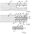
- Fig. 4 illustrates a fibre board without veneer sheets and edge strips.
- a single cylindrical blind hole 9 is illustrated in the fibre board 2. Inside the blind hole there is indicated an applied bonding agent layer 10 which largely covers the whole inner surface 11 of the hole 9.
- Fig. 5 illustrates how a dowel 12 is inserted in the hole 10.
- a part of the bonding agent 9 has penetrated out in the interspace indicated by 13 between the fibres indicated as 14 in the fibre board 2.
- the extraction is indicated by the arrows 15.
- the dowel has nine annular grooves 16 that each has a semicircular cross-section. These grooves will be filled with a bonding agent as well as the boundary surface or the slot 17 between the outer side 18 of the dowel 12 and the inner side of the hole 9 are also filled with a bonding agent joint.
- the dowel comprises a central boring 19 for receiving a screw.
- Fig. 7 is a schematic view of the door shown in Figs. 1 - 3 in which a dowel is mounted in a hole as explained with reference to Figs. 4 - 6. It appears that two dowels intended for receiving a hinge fitting (not shown) are provided.
- the edge strip 7 there is provided a recess 20 with a configuration corresponding to the configuration of the plate section of the hinge.
- the recess 20 has a bottom 21 which will be flush with the upper side 22 on the dowels 12.
- a plane contact surface for the plate section of the hinge is established.
- Fig. 8 illustrates a nozzle 23 used by the method according to the invention.
- the nozzle 23 has a handle part 24 which is connected with a (not shown) container for bonding agent.
- the bonding agent may, for example, be pressurised for being advanced to the nozzle 23.
- the nozzle furthermore comprises an insertion part 25 for placing in the hole 9.
- the nozzle comprises two outlet openings 26 which are provided in each their cylindrical groove 27. Alternatively, there may be provided several openings for establishing as even distribution of the bonding agent layer 10 in the hole 9 as possible.
- a pump is activated for discharging a well-defined amount of bonding agent which is determined from the actual density of the board.
- the bonding agent used is a polyvinyl acetate glue with a viscosity of about 15,000 mPa*s. After the glue has been applied to the hole, the nozzle 23 and the dowel 12 may be pressed into the hole provided with bonding agent. The bonding agent will then set at room temperature. In the same process line it is possible to attach hinges and lock cases before a door is put on stock as tensile strengths will not arise in hinges or lock cases. Alternatively, hinges and lock cases can be mounted at a later time after the setting of the bonding agent while the door board is stored before delivery.
Abstract


Description
- The present invention concerns a fastening device for a screw for securing another item, such as a plate section for a hinge, a lock case or the like, in a blind hole in a fibre board comprising fibres of wood, flax, straw or the like, which are compressed and bonded together to a board having a stable shape and preferably being provided with a coating on its surfaces.
- Furthermore, the invention concerns a method for mounting a screw for securing another item, such as a plate section for a hinge, a lock case or the like in a blind hole in a fibre board comprising fibres of wood, flax, straw or the like, which are compressed and bonded together to a board which has a stable shape and which preferably is provided with a coating, e.g. comprising veneer, film, paint, or the like, on its surfaces.
- Within recent years, smooth boards for use in furniture, doors and other building structures have been made as sandwich constructions consisting of two thin sheets and a supporting frame with a core, e.g. in the form of honeycomb cardboard or the like.
- This construction is expensive and complicated and implies risk of weaknesses in the form of tensions and cracks between frame and core.
- Even if the fibre boards are having numerous advantageous properties as core element, they have had a relatively limited extension to natural fibre boards or building boards where a certain weight has to be carried in the board. This weight may be the weight of the board itself as in the case of doors. Alternatively, the case may be carrying the weight of objects suspended on the board, which is the case in connection with hooks mounted on a building board.
- When a screw hitherto has been screwed into a fibre board, often there has been a risk that the screw is pulled out at some time due to the load on the screw and due to the porous structure in the fibre board.
- It is the purpose of the invention to indicate a novel technique for establishing a fastener for use in fibre boards so that it is possible pre-fabricate the fibre boards in such a way that they are ready to receive a screw for fastening an item on the fibre board in a quick and simple way while at the same time there is achieved a great strength and little risk that the screw is released from the fibre board in a structure which may consist of an example in the shape of a natural fibre board.
- This is achieved by a fasting device of the kind mentioned in the introduction which is peculiar in that in combination it includes a dowel with dimensions corresponding to the blind hole and with a number of grooves extending along the periphery, and a bonding agent which fills up the boundary surface between the dowel and the hole and is pressed out into the surrounding natural fibre mass at the inserting of the dowel, and that the dowel comprises a central boring for receiving the screw.
- The method according to the invention is peculiar in that a hole is bored into the fibre board, that a dowel is with dimension corresponding to the blind hole is provided and with a number of grooves extending along the periphery and with a central boring for receiving the screw, that a fluid bonding agent is filled into the hole, that the dowel is pressed into the hole in that the bonding agent hereby is pressed out into the surrounding natural fibre mass and fills up the boundary surface between the dowel and the hole, that the bonding agent is set, and that the screw is mounted hereafter.
- By applying the dowel, which fits in the hole in the fibre board, in a press fit, the bonding agent filled into the hole will be pressed out into and partly fill up the cavities between the fibres surrounding the hole. At the same time, the slot between the dowel and the hole is filled up with bonding agent which also fills up the grooves in the dowel. With this construction, an increased strength is achieved due to the bonding together of the fibres around the hole simultaneously with there is established a bonding agent body extending from the wood fibres through the boundary surface and into the grooves in the surface of the dowel.
- A surprisingly great tensile strength has appeared by this construction. However, it has also surprisingly appeared that grooves extending in the longitudinal direction of the dowel does not give approximately the same tensile strength as grooves extending in the peripheral direction of the dowel.
- The dowel will preferably be cylindric, and the grooves will be formed in a plane perpendicular to the longitudinal direction of the dowel. The grooves may have any cross-section but preferably have approximately semi-circular cross-section. Furthermore, it has appeared advantageous that the grooves constitute between half and one quarter, preferably one third of the surface of the dowel with the purpose of achieving maximum resistance against extraction of the dowel.
- By practical experiments it has appeared possible to resist extraction of the dowel by exerting a tensile force up to 500 kg.
- When bonding agent has been filled into the hole, this occurs preferably by means of a nozzle having several openings which extend over the depth of the hole. Hereby it is ensured that before inserting the dowel, bonding agent has not only been provided at the bottom of the hole but also an even layer of bonding agent over the whole depth of the hole.
- Preferably, there is applied a bonding agent of polyvinyl acetate dispersion type having a viscosity between 10,000 and 20,000, preferably about 15,000 mPa*s. Additionally, there is used an amount of bonding agent so that the cavities in the fibre board are filled up in an area of 4 - 20 mm and preferably 5 - 8 out into the fibre board. Thus a part bonding agent impregnation and bonding together of fibre material is achieved when the dowel is inserted. The used dowel is preferably of wood, but may alternatively be made of other material, as for instance metal or plastic materials.
- Particularly with boards to be used for doors, the coating will include an edge of film or wood strip ensuring that in a porous edge a recess may be provided, preferably by milling, with a profile corresponding to the shape of the plate section of the hinge or the lock case. By such a solution, an edge strip on the fibre board is unnecessary. If an edge strip is used, by milling such a recess in the edge strip there is achieved a secure guiding and easy mounting of hinges and lock cases.
- When a milling is performed, the upper side of the dowel will be flush with the bottom of the recess so that a plane support surface for the plate section appears.
- The fibre board may be made of different kinds of cellulose fibres, straw fibres, wood fibres, flax fibres, etc. In an advantageous embodiment, the fibre board comprises flax fibres and usually has a density of between 350 and 500, preferably between 440 and 470 kg/m3. With such density there is achieved a natural fibre board which appears genuine and at the same time provides the strength needed for avoiding holes by impact action on the laminated side surfaces. Such a fibre board is particularly suited as board in a door as it will be more fireproof and more soundproof than traditional sandwich doors.
- In a specific embodiment of the fastener for use in a door with a thickness of 38 mm thick, a 60 mm long wooden dowel with a diameter of 16 mm is used. There are provided 9 annular grooves with a semicircular cross-section with a radius of 1 mm, and the bonding agent is a polyvinyl acetate glue forming a tough elastic glue joint which meets the standard EN 204 D3. The bonding agent is fluid and has a viscosity of about 15,000 mPa*s, brookfield LVT,
spindle 4,6 rpm, 25°C. It is a glue which is drying relatively quickly at room temperature. Thus it will be possible to perform bonding in process equipment and let the glue harden at a subsequent transport storage from the process line where the bonding agent and the dowel are placed in the hole. Thus there is no requirement for any heat supply to achieve the necessary strength/hardening in the bonding agent. - Even though a specific example with a fibre board having a thickness of 38 mm is mentioned above, it is possible to use thicknesses between 30 and 50 mm for dowels with the same dimensions.
- Also, it is preferred that the dowel comprises a central boring for receiving the screw used for securing an item. As the dowel preferably is to be of relatively hard and compact material, a central boring will be suitable for avoiding splitting a wooden dowel. Also, use of a central boring corresponding to the core dimension of a wood screw enables establishing a well-defined strength in connection with screw and dowel. It may be preferred that between the screw and the dowel there is a lesser force for extraction than the force necessary for pulling the dowel out of the natural fibre board. By a possible overload, the board may be reused by using a larger screw. By dowels resisting a pull of 500 kg for extraction it may thus be advantageous that the central boring and the screw are designed so that the screw may be pulled out at a load of about 300 kg.
- The invention will now be explained in more detail with reference to the accompanying drawing, where:
- Fig. 1
- shows a plan view of a natural fibre board for use as door by using a fastener according to the invention,
- Figs. 2 and 3
- shows a section through the natural fibre board in Fig. 1 according to the lines II-II and III-III, respectively,
- Fig. 4
- shows a partial section through a fibre board with a blind hole for receiving a dowel,
- Fig. 5
- shows a view corresponding to Fig. 4 with the dowel inserted in the hole,
- Fig. 6
- shows a section through the dowel shown in fig. 5,
- Fig. 7
- illustrates a partial perspective view of a door board with fastener according to the invention and with a milling in an edge strip for receiving a hinge fitting, and
- Fig. 8
- shows a view for illustrating a bonding agent nozzle for use in the method according to the invention.
- In the following, identical and corresponding elements will be designated with the same reference number. Therefore, no specific explanation will be given in connection with each single Figure.
- In Figs. 1 - 3 is seen a
natural fibre board 1 intended to be used as door. Thenatural fibre board 1 comprises acentral fibre board 2 which at two opposite faces are provided with a 0.5 mm veneer covering 3,4. At the side edge at bottom and top there is provided 1 mm solidwood edge strip 5,6, and at opposite side edges in the height of the board there are provided 3 mm solid wood edge strips 7,8. - The
veneer sheet 2 is pressed and glued to a board with stable shape. The actual board has a thickness of 38 mm and has a density between 440 and 470 kg/m3. It has a bending strength of 6-7 N/mm2 and a tensile strength of 0.14-0.16 N/mm2. - The veneer sheet typically has a moisture content of 7-10%. The
fibre board 2 is made of flax fibres. - Fig. 4 illustrates a fibre board without veneer sheets and edge strips. A single cylindrical
blind hole 9 is illustrated in thefibre board 2. Inside the blind hole there is indicated an appliedbonding agent layer 10 which largely covers the wholeinner surface 11 of thehole 9. - Fig. 5 illustrates how a
dowel 12 is inserted in thehole 10. Hereby, a part of thebonding agent 9 has penetrated out in the interspace indicated by 13 between the fibres indicated as 14 in thefibre board 2. The extraction is indicated by thearrows 15. As it clearly appears from Fig. 6, the dowel has nineannular grooves 16 that each has a semicircular cross-section. These grooves will be filled with a bonding agent as well as the boundary surface or the slot 17 between the outer side 18 of thedowel 12 and the inner side of thehole 9 are also filled with a bonding agent joint. - The dowel comprises a
central boring 19 for receiving a screw. - Fig. 7 is a schematic view of the door shown in Figs. 1 - 3 in which a dowel is mounted in a hole as explained with reference to Figs. 4 - 6. It appears that two dowels intended for receiving a hinge fitting (not shown) are provided. In the
edge strip 7 there is provided arecess 20 with a configuration corresponding to the configuration of the plate section of the hinge. Therecess 20 has a bottom 21 which will be flush with theupper side 22 on thedowels 12. Hereby is established a plane contact surface for the plate section of the hinge. - Fig. 8 illustrates a
nozzle 23 used by the method according to the invention. Thenozzle 23 has ahandle part 24 which is connected with a (not shown) container for bonding agent. The bonding agent may, for example, be pressurised for being advanced to thenozzle 23. The nozzle furthermore comprises aninsertion part 25 for placing in thehole 9. The nozzle comprises twooutlet openings 26 which are provided in each theircylindrical groove 27. Alternatively, there may be provided several openings for establishing as even distribution of thebonding agent layer 10 in thehole 9 as possible. When thenozzle 23 has been inserted into thehole 9, a pump is activated for discharging a well-defined amount of bonding agent which is determined from the actual density of the board. - The bonding agent used is a polyvinyl acetate glue with a viscosity of about 15,000 mPa*s. After the glue has been applied to the hole, the
nozzle 23 and thedowel 12 may be pressed into the hole provided with bonding agent. The bonding agent will then set at room temperature. In the same process line it is possible to attach hinges and lock cases before a door is put on stock as tensile strengths will not arise in hinges or lock cases. Alternatively, hinges and lock cases can be mounted at a later time after the setting of the bonding agent while the door board is stored before delivery.
Claims (10)
- A fastener for a screw for securing another item, such as a plate section for a hinge, a lock case or the like, in a blind hole in a fibre board comprising fibres of wood, flax, straw or the like, which are compressed and bonded together to a board having a stable shape and preferably being provided with a coating on its surfaces, characterised in that in combination it includes a dowel with dimensions corresponding to the blind hole and with a number of grooves extending along the periphery, and a bonding agent which fills up the boundary surface between the dowel and the hole and is pressed out into the surrounding natural fibre mass at the inserting of the dowel, and that the dowel comprises a central boring for receiving the screw.
- A fastener according to claim 1,characterised in that the coating comprises film or veneer, and that herein there is provided a recess with a profile corresponding to the shape of the plate section, and that the upper side of the dowel is flush with the bottom of the recess.
- A fastener according to claim 1 or 2, characterised in that the dowel is cylindric, that the grooves are formed in a plane perpendicular to the longitudinal direction of the dowel and has an approximately semicircular cross-section.
- A fastener according to claim 3, characterised in that the grooves constitute between ½ and 1/4, preferably about 1/3 of the surface of the dowel.
- A fastener according to any preceding claim, characterised in that the bonding agent is a polyvinyl acetate dispersion type and has a viscosity between 10,000 and 20,000, preferably about 15,000 mPa*s.
- A fastener according to any preceding claim, characterised in that the fibre board comprises flax fibres and has a density of between 350 and 500, preferably between 440 and 470 kg/m3.
- A fastener according to any preceding claim for fastening door hinges at the side edge of a board, characterised in that the fibre board is a 38 mm thick flax board with a density of 440-470 kg/m3, that the dowel is a 60 mm long wooden dowel with a diameter of 16 mm, that 9 annular grooves are provided with a semicircular cross-section with radius 1 mm, and that the bonding agent is a polyvinyl acetate glue forming a glue joint which meets the standard EN 204 D3.
- A method for mounting a screw for securing another item, such as a plate section for a hinge, a lock case or the like in a blind hole in a fibre board comprising fibres of wood, flax, straw or the like, which are compressed and bonded together to a board which has a stable shape and which preferably is provided with a coating on its surfaces, characterised in that a hole is bored in the fibre board, that a dowel is with dimension corresponding to the blind hole is provided and with a number of grooves extending along the periphery and with a central boring for receiving the screw, that a fluid bonding agent is filled into the hole, that the dowel is pressed into the hole in that the bonding agent hereby is pressed out into the surrounding natural fibre mass and fills up the boundary surface between the dowel and the hole, that the bonding agent is set, and that the screw is mounted hereafter.
- A method according to claim 8, characterised in that the bonding agent is filled into the hole by using a nozzle having plural openings distributed over the length of the nozzle.
- A method according to claim 8 or 9, characterised in that the setting occurs at room temperature and during subsequent storage and transport of the fibre board from a process line where the bonding agent and the dowel are placed.
Priority Applications (1)
| Application Number | Priority Date | Filing Date | Title |
|---|---|---|---|
| DK01128588T DK1215403T3 (en) | 2000-12-12 | 2001-11-30 | Method of providing a dowel in a fibrous sheet and such fibrous sheet |
Applications Claiming Priority (2)
| Application Number | Priority Date | Filing Date | Title |
|---|---|---|---|
| DKPA200001856 | 2000-12-12 | ||
| DK200001856 | 2000-12-12 |
Publications (3)
| Publication Number | Publication Date |
|---|---|
| EP1215403A2 true EP1215403A2 (en) | 2002-06-19 |
| EP1215403A3 EP1215403A3 (en) | 2002-11-06 |
| EP1215403B1 EP1215403B1 (en) | 2006-05-31 |
Family
ID=8159900
Family Applications (1)
| Application Number | Title | Priority Date | Filing Date |
|---|---|---|---|
| EP01128588A Expired - Lifetime EP1215403B1 (en) | 2000-12-12 | 2001-11-30 | Method for providing a dowel in a fibre board and corresponding fibre board |
Country Status (4)
| Country | Link |
|---|---|
| EP (1) | EP1215403B1 (en) |
| AT (1) | ATE328208T1 (en) |
| DE (1) | DE60120095D1 (en) |
| DK (1) | DK1215403T3 (en) |
Cited By (2)
| Publication number | Priority date | Publication date | Assignee | Title |
|---|---|---|---|---|
| CN101482137B (en) * | 2008-01-09 | 2010-09-08 | 财团法人石材暨资源产业研究发展中心 | Method for inlaying screw seat into non-metal member, and non-metal member apparatus with screw seat |
| GB2482177A (en) * | 2010-07-23 | 2012-01-25 | Vincent Peacock | Timber wedge anchor |
Family Cites Families (5)
| Publication number | Priority date | Publication date | Assignee | Title |
|---|---|---|---|---|
| US4370372A (en) * | 1981-03-30 | 1983-01-25 | Advanced Technology & Research, Inc. | Method of joining honeycomb panels using a fastener element |
| US4729705A (en) * | 1987-02-02 | 1988-03-08 | Atr International, Inc. | Insert fastener in a lightweight panel |
| FR2641044B1 (en) * | 1988-12-28 | 1991-03-22 | Plombelec | |
| US5733083A (en) * | 1995-09-18 | 1998-03-31 | United Industries Corporation | Adhesive insert anchor |
| NL1004990C2 (en) * | 1997-01-14 | 1998-07-15 | Insulcon Europ B V | Anchoring element as well as a method of coating a substrate. |
-
2001
- 2001-11-30 AT AT01128588T patent/ATE328208T1/en not_active IP Right Cessation
- 2001-11-30 EP EP01128588A patent/EP1215403B1/en not_active Expired - Lifetime
- 2001-11-30 DE DE60120095T patent/DE60120095D1/en not_active Expired - Lifetime
- 2001-11-30 DK DK01128588T patent/DK1215403T3/en active
Non-Patent Citations (1)
| Title |
|---|
| None |
Cited By (3)
| Publication number | Priority date | Publication date | Assignee | Title |
|---|---|---|---|---|
| CN101482137B (en) * | 2008-01-09 | 2010-09-08 | 财团法人石材暨资源产业研究发展中心 | Method for inlaying screw seat into non-metal member, and non-metal member apparatus with screw seat |
| GB2482177A (en) * | 2010-07-23 | 2012-01-25 | Vincent Peacock | Timber wedge anchor |
| GB2482177B (en) * | 2010-07-23 | 2012-08-01 | Vincent Peacock | The timber wedge anchor |
Also Published As
| Publication number | Publication date |
|---|---|
| ATE328208T1 (en) | 2006-06-15 |
| DE60120095D1 (en) | 2006-07-06 |
| EP1215403B1 (en) | 2006-05-31 |
| EP1215403A3 (en) | 2002-11-06 |
| DK1215403T3 (en) | 2006-10-02 |
Similar Documents
| Publication | Publication Date | Title |
|---|---|---|
| US8317959B2 (en) | Method of making multi-ply door core, multi-ply door core, and door manufactured therewith | |
| US5267425A (en) | I-beam joint | |
| US10731332B1 (en) | Composite reinforced wood stud for residential and commercial buildings | |
| US2703443A (en) | Composite door construction and method of making the same | |
| WO2003093686A1 (en) | Building board and method of fastening one | |
| US4974389A (en) | Wooden structural member | |
| EP1215403B1 (en) | Method for providing a dowel in a fibre board and corresponding fibre board | |
| KR200389695Y1 (en) | Interior materials having natural wood sheet layer piled on HPM layer | |
| CA2369014C (en) | Hinge assembly and method of attachment for composite panel doors | |
| US4003163A (en) | Door construction | |
| JPS591806A (en) | Dowel for connecting small-width sawn board | |
| US2376698A (en) | Fastening for fibrous boards | |
| JP2860062B2 (en) | Floor material production method | |
| JPH03247859A (en) | Soundproof floor | |
| TWI784478B (en) | Flat-pack furniture and composite post thereof | |
| CN111216209B (en) | Novel artificial wood floor | |
| CA1038148A (en) | Method of manufacturing skin stressed building elements | |
| JPH08119711A (en) | Structure for reinforcing rock wool board and method for reinforcing | |
| JP4893594B2 (en) | Plate-shaped material and vertical frame for installing an opening door using the same | |
| DE102017118546B4 (en) | Wall construction with a supporting framework | |
| JPS6160215B2 (en) | ||
| JPH05337903A (en) | Using method for veneer laminate material as structural member of fitting member for building | |
| JP2799333B2 (en) | Composite panel | |
| JP3169806B2 (en) | Composite board joint structure | |
| JP3438476B2 (en) | Storage cabinet |
Legal Events
| Date | Code | Title | Description |
|---|---|---|---|
| PUAI | Public reference made under article 153(3) epc to a published international application that has entered the european phase |
Free format text: ORIGINAL CODE: 0009012 |
|
| AK | Designated contracting states |
Kind code of ref document: A2 Designated state(s): AT BE CH CY DE DK ES FI FR GB GR IE IT LI LU MC NL PT SE TR |
|
| AX | Request for extension of the european patent |
Free format text: AL;LT;LV;MK;RO;SI |
|
| PUAL | Search report despatched |
Free format text: ORIGINAL CODE: 0009013 |
|
| AK | Designated contracting states |
Kind code of ref document: A3 Designated state(s): AT BE CH CY DE DK ES FI FR GB GR IE IT LI LU MC NL PT SE TR |
|
| AX | Request for extension of the european patent |
Free format text: AL;LT;LV;MK;RO;SI |
|
| RIC1 | Information provided on ipc code assigned before grant |
Free format text: 7F 16B 13/14 A, 7F 16B 11/00 B |
|
| 17P | Request for examination filed |
Effective date: 20030505 |
|
| AKX | Designation fees paid |
Designated state(s): AT BE CH CY DE DK ES FI FR GB GR IE IT LI LU MC NL PT SE TR |
|
| 17Q | First examination report despatched |
Effective date: 20040303 |
|
| GRAP | Despatch of communication of intention to grant a patent |
Free format text: ORIGINAL CODE: EPIDOSNIGR1 |
|
| RTI1 | Title (correction) |
Free format text: METHOD FOR PROVIDING A DOWEL IN A FIBRE BOARD AND CORRESPONDING FIBRE BOARD |
|
| GRAS | Grant fee paid |
Free format text: ORIGINAL CODE: EPIDOSNIGR3 |
|
| GRAA | (expected) grant |
Free format text: ORIGINAL CODE: 0009210 |
|
| AK | Designated contracting states |
Kind code of ref document: B1 Designated state(s): AT BE CH CY DE DK ES FI FR GB GR IE IT LI LU MC NL PT SE TR |
|
| PG25 | Lapsed in a contracting state [announced via postgrant information from national office to epo] |
Ref country code: IT Free format text: LAPSE BECAUSE OF FAILURE TO SUBMIT A TRANSLATION OF THE DESCRIPTION OR TO PAY THE FEE WITHIN THE PRESCRIBED TIME-LIMIT;WARNING: LAPSES OF ITALIAN PATENTS WITH EFFECTIVE DATE BEFORE 2007 MAY HAVE OCCURRED AT ANY TIME BEFORE 2007. THE CORRECT EFFECTIVE DATE MAY BE DIFFERENT FROM THE ONE RECORDED. Effective date: 20060531 Ref country code: AT Free format text: LAPSE BECAUSE OF FAILURE TO SUBMIT A TRANSLATION OF THE DESCRIPTION OR TO PAY THE FEE WITHIN THE PRESCRIBED TIME-LIMIT Effective date: 20060531 Ref country code: LI Free format text: LAPSE BECAUSE OF FAILURE TO SUBMIT A TRANSLATION OF THE DESCRIPTION OR TO PAY THE FEE WITHIN THE PRESCRIBED TIME-LIMIT Effective date: 20060531 Ref country code: BE Free format text: LAPSE BECAUSE OF FAILURE TO SUBMIT A TRANSLATION OF THE DESCRIPTION OR TO PAY THE FEE WITHIN THE PRESCRIBED TIME-LIMIT Effective date: 20060531 Ref country code: NL Free format text: LAPSE BECAUSE OF FAILURE TO SUBMIT A TRANSLATION OF THE DESCRIPTION OR TO PAY THE FEE WITHIN THE PRESCRIBED TIME-LIMIT Effective date: 20060531 Ref country code: FI Free format text: LAPSE BECAUSE OF FAILURE TO SUBMIT A TRANSLATION OF THE DESCRIPTION OR TO PAY THE FEE WITHIN THE PRESCRIBED TIME-LIMIT Effective date: 20060531 Ref country code: CH Free format text: LAPSE BECAUSE OF FAILURE TO SUBMIT A TRANSLATION OF THE DESCRIPTION OR TO PAY THE FEE WITHIN THE PRESCRIBED TIME-LIMIT Effective date: 20060531 |
|
| REG | Reference to a national code |
Ref country code: GB Ref legal event code: FG4D Ref country code: CH Ref legal event code: EP |
|
| REG | Reference to a national code |
Ref country code: IE Ref legal event code: FG4D |
|
| REF | Corresponds to: |
Ref document number: 60120095 Country of ref document: DE Date of ref document: 20060706 Kind code of ref document: P |
|
| PG25 | Lapsed in a contracting state [announced via postgrant information from national office to epo] |
Ref country code: DE Free format text: LAPSE BECAUSE OF FAILURE TO SUBMIT A TRANSLATION OF THE DESCRIPTION OR TO PAY THE FEE WITHIN THE PRESCRIBED TIME-LIMIT Effective date: 20060901 |
|
| PG25 | Lapsed in a contracting state [announced via postgrant information from national office to epo] |
Ref country code: ES Free format text: LAPSE BECAUSE OF FAILURE TO SUBMIT A TRANSLATION OF THE DESCRIPTION OR TO PAY THE FEE WITHIN THE PRESCRIBED TIME-LIMIT Effective date: 20060911 |
|
| REG | Reference to a national code |
Ref country code: SE Ref legal event code: TRGR |
|
| REG | Reference to a national code |
Ref country code: DK Ref legal event code: T3 |
|
| PG25 | Lapsed in a contracting state [announced via postgrant information from national office to epo] |
Ref country code: PT Free format text: LAPSE BECAUSE OF FAILURE TO SUBMIT A TRANSLATION OF THE DESCRIPTION OR TO PAY THE FEE WITHIN THE PRESCRIBED TIME-LIMIT Effective date: 20061031 |
|
| NLV1 | Nl: lapsed or annulled due to failure to fulfill the requirements of art. 29p and 29m of the patents act | ||
| PG25 | Lapsed in a contracting state [announced via postgrant information from national office to epo] |
Ref country code: MC Free format text: LAPSE BECAUSE OF NON-PAYMENT OF DUE FEES Effective date: 20061130 Ref country code: IE Free format text: LAPSE BECAUSE OF NON-PAYMENT OF DUE FEES Effective date: 20061130 |
|
| REG | Reference to a national code |
Ref country code: CH Ref legal event code: PL |
|
| PLBE | No opposition filed within time limit |
Free format text: ORIGINAL CODE: 0009261 |
|
| STAA | Information on the status of an ep patent application or granted ep patent |
Free format text: STATUS: NO OPPOSITION FILED WITHIN TIME LIMIT |
|
| EN | Fr: translation not filed | ||
| 26N | No opposition filed |
Effective date: 20070301 |
|
| PG25 | Lapsed in a contracting state [announced via postgrant information from national office to epo] |
Ref country code: GR Free format text: LAPSE BECAUSE OF FAILURE TO SUBMIT A TRANSLATION OF THE DESCRIPTION OR TO PAY THE FEE WITHIN THE PRESCRIBED TIME-LIMIT Effective date: 20060901 Ref country code: FR Free format text: LAPSE BECAUSE OF FAILURE TO SUBMIT A TRANSLATION OF THE DESCRIPTION OR TO PAY THE FEE WITHIN THE PRESCRIBED TIME-LIMIT Effective date: 20070309 |
|
| PG25 | Lapsed in a contracting state [announced via postgrant information from national office to epo] |
Ref country code: TR Free format text: LAPSE BECAUSE OF FAILURE TO SUBMIT A TRANSLATION OF THE DESCRIPTION OR TO PAY THE FEE WITHIN THE PRESCRIBED TIME-LIMIT Effective date: 20060531 Ref country code: LU Free format text: LAPSE BECAUSE OF NON-PAYMENT OF DUE FEES Effective date: 20061130 |
|
| PG25 | Lapsed in a contracting state [announced via postgrant information from national office to epo] |
Ref country code: FR Free format text: LAPSE BECAUSE OF FAILURE TO SUBMIT A TRANSLATION OF THE DESCRIPTION OR TO PAY THE FEE WITHIN THE PRESCRIBED TIME-LIMIT Effective date: 20060531 Ref country code: CY Free format text: LAPSE BECAUSE OF FAILURE TO SUBMIT A TRANSLATION OF THE DESCRIPTION OR TO PAY THE FEE WITHIN THE PRESCRIBED TIME-LIMIT Effective date: 20060531 |
|
| PGFP | Annual fee paid to national office [announced via postgrant information from national office to epo] |
Ref country code: DK Payment date: 20131125 Year of fee payment: 13 |
|
| PGFP | Annual fee paid to national office [announced via postgrant information from national office to epo] |
Ref country code: SE Payment date: 20131127 Year of fee payment: 13 Ref country code: GB Payment date: 20131127 Year of fee payment: 13 |
|
| REG | Reference to a national code |
Ref country code: DK Ref legal event code: EBP Effective date: 20141130 |
|
| GBPC | Gb: european patent ceased through non-payment of renewal fee |
Effective date: 20141130 |
|
| PG25 | Lapsed in a contracting state [announced via postgrant information from national office to epo] |
Ref country code: SE Free format text: LAPSE BECAUSE OF NON-PAYMENT OF DUE FEES Effective date: 20141201 |
|
| REG | Reference to a national code |
Ref country code: SE Ref legal event code: EUG |
|
| PG25 | Lapsed in a contracting state [announced via postgrant information from national office to epo] |
Ref country code: DK Free format text: LAPSE BECAUSE OF NON-PAYMENT OF DUE FEES Effective date: 20141130 Ref country code: GB Free format text: LAPSE BECAUSE OF NON-PAYMENT OF DUE FEES Effective date: 20141130 |