EP1220009A2 - Controlling engulfing and sequestering magnetic pads - Google Patents
Controlling engulfing and sequestering magnetic pads Download PDFInfo
- Publication number
- EP1220009A2 EP1220009A2 EP01310676A EP01310676A EP1220009A2 EP 1220009 A2 EP1220009 A2 EP 1220009A2 EP 01310676 A EP01310676 A EP 01310676A EP 01310676 A EP01310676 A EP 01310676A EP 1220009 A2 EP1220009 A2 EP 1220009A2
- Authority
- EP
- European Patent Office
- Prior art keywords
- gyricon
- ball
- magnetic
- balls
- pigment
- Prior art date
- Legal status (The legal status is an assumption and is not a legal conclusion. Google has not performed a legal analysis and makes no representation as to the accuracy of the status listed.)
- Granted
Links
Images
Classifications
-
- G—PHYSICS
- G09—EDUCATION; CRYPTOGRAPHY; DISPLAY; ADVERTISING; SEALS
- G09F—DISPLAYING; ADVERTISING; SIGNS; LABELS OR NAME-PLATES; SEALS
- G09F9/00—Indicating arrangements for variable information in which the information is built-up on a support by selection or combination of individual elements
- G09F9/30—Indicating arrangements for variable information in which the information is built-up on a support by selection or combination of individual elements in which the desired character or characters are formed by combining individual elements
- G09F9/37—Indicating arrangements for variable information in which the information is built-up on a support by selection or combination of individual elements in which the desired character or characters are formed by combining individual elements being movable elements
- G09F9/375—Indicating arrangements for variable information in which the information is built-up on a support by selection or combination of individual elements in which the desired character or characters are formed by combining individual elements being movable elements the position of the elements being controlled by the application of a magnetic field
-
- G—PHYSICS
- G02—OPTICS
- G02B—OPTICAL ELEMENTS, SYSTEMS OR APPARATUS
- G02B26/00—Optical devices or arrangements for the control of light using movable or deformable optical elements
- G02B26/02—Optical devices or arrangements for the control of light using movable or deformable optical elements for controlling the intensity of light
- G02B26/026—Optical devices or arrangements for the control of light using movable or deformable optical elements for controlling the intensity of light based on the rotation of particles under the influence of an external field, e.g. gyricons, twisting ball displays
Landscapes
- Physics & Mathematics (AREA)
- General Physics & Mathematics (AREA)
- Engineering & Computer Science (AREA)
- Theoretical Computer Science (AREA)
- Health & Medical Sciences (AREA)
- Life Sciences & Earth Sciences (AREA)
- Molecular Biology (AREA)
- Optics & Photonics (AREA)
- Electrochromic Elements, Electrophoresis, Or Variable Reflection Or Absorption Elements (AREA)
- Devices For Indicating Variable Information By Combining Individual Elements (AREA)
Abstract
Description
- The invention relates to the field of visual displays. More particularly, the invention relates to the production of balls used in a gyricon or twisting ball visual display and to the production of gyricon balls having sequestered magnetic pads.
- Paper has traditionally been a preferred medium for the presentation and display of text and images. Paper has several characteristics that make it a desirable display medium, including the fact that it is lightweight, thin, portable, flexible, foldable, high-contrast, low-cost, relatively permanent, and readily configured into a myriad of shapes. It can maintain its displayed images without using any electricity. Paper can also be read in ambient light and can be written or marked upon with a pen, pencil, paintbrush, or any number of other implements, including a computer printer.
- Unfortunately, paper is not well suited for real-time display purposes. Real-time imagery from computer, video, or other sources cannot be displayed directly with paper, but must be displayed by other means, such as by a cathode-ray tube (CRT) display or a liquid-crystal display (LCD). However, real-time display media lack many of the desirable qualities of paper, such as physical flexibility and stable retention of the displayed image in the absence of an electric power source.
- Electric paper combines the desirable qualities of paper with those of real-time display media. Like ordinary paper, electric paper can be written and erased, can be read in ambient light and can retain imposed information in the absence of an electric field or other external retaining force. Also like ordinary paper, electric paper can be made in the form of a light-weight, flexible, durable sheet that can be folded or rolled into a tubular form about any axis and placed into a shirt or coat pocket, and then later retrieved, re-straightened, and read without loss of information. Yet unlike ordinary paper, electric paper can be used to display full-motion and other real-time imagery as well as still images and text. Thus, electric paper can be used in a computer system display screen or a television.
- The gyricon, also called the twisting-ball display, rotary ball display, particle display, dipolar particle light valve, etc., provides a technology for making electric paper. A gyricon display is a display that can be altered or addressed. A gyricon display is made up of a multiplicity of optically anisotropic balls which can be selectively rotated to present a desired surface to an observer.
- The optical anisotropy of the gyricon balls is provided by dividing the surface of each gyricon ball into two portions. One portion of the surface of each gyricon ball has a first light reflectance or color. The other portion of the surface of the gyricon ball has a different color or a different light reflectance. For example, a gyricon ball can have two distinct hemispheres, one black and the other white. Additionally, each hemisphere can have a distinct electrical characteristic with respect to a dielectric fluid. Accordingly, the gyricon balls are electrically as well as optically anisotropic. The black-and-white gyricon balls are embedded in a sheet of optically transparent material, such as an elastomer layer, that contains a multiplicity of spheroidal cavities. Each of the spheroidal cavities is permeated by a transparent dielectric fluid, such as a plasticizer. The fluid-filled cavities accommodate the gyricon balls, one gyricon ball per cavity, to prevent the balls from migrating within the sheet. Each cavity is slightly larger than the size of the gyricon ball so that each gyricon ball can rotate or move slightly within its cavity.
- A gyricon ball can be selectively rotated within its respective fluid-filled cavity by applying an electric field, so that either the black or white hemisphere of the gyricon ball is exposed to an observer viewing the surface of the sheet. By applying an electric field in two dimensions, for example, using a matrix addressing scheme, the black and white sides of the balls can be caused to appear as the image elements, e.g., pixels or subpixels, of a displayed image.
- The various exemplary embodiments of the systems and methods of this invention are directed to addressing gyricon displays in which magnetic materials are added to the composition of the gyricon balls and magnetic fields are used to augment the usual electrical addressing fields.
- The various exemplary embodiments of the systems and methods of this invention are directed to making gyricon balls with magnetic pads that allows them to be located into two different positions by means of a further stationary magnetic pad. This allows creation of a strong, engineered threshold for gyricon ball rotation, rather than depending upon the naturally occurring threshold.
- The various exemplary embodiments of the systems and methods of this invention are directed to sequestering, i.e., hiding, the magnetic pads from sight so they do not decrement the brightness of the display.
- The various exemplary embodiments of the systems and methods of this invention are further directed to controlling the engulfing of one hemisphere of a bichromal ball by the other hemisphere of the bichromal ball during the fabrication of the bichromal ball.
- In the various exemplary embodiments of the systems and methods of this invention, the magnetic pads, which may be dark in color and which may subtend a substantial part of the visible portion of the white side of the gyricon ball, are sequestered.
- In the various exemplary embodiments of the systems and methods of this invention, the gyricon balls are made from a polyethylene plastic, wherein the white sides of the balls are made from this plastic, with titanium dioxide dispersed within, and the black sides of the balls are made from this same plastic, with a black pigment, as well as a chemical called a charging agent, dispersed in within.
- In the various exemplary embodiments of the systems and methods of this invention, the magnetic pads are made by dispersing magnetic pigments into the polyethylene plastic.
- In the various exemplary embodiments of the systems and methods of this invention, the magnetic pads on the white sides of the gyricon balls are sequestered.
- In the various exemplary embodiments of the systems and methods of this invention, the addition of aluminum octoate to either the white side of the gyricon ball or the black side of the gyricon ball causes the pigmented plastic on that side of the ball to attempt to envelope the pigmented plastic on parts of the ball that do not have aluminum octoate added during the ball making process.
- In the various exemplary embodiments of the systems and methods of this invention, adding aluminum octoate to the white pigmented plastic causes the magnetic pads on the white sides of the gyricon balls to be enveloped during the ball making process.
- In the various exemplary embodiments of the systems and methods of this invention, adding aluminum octoate to the pigmented plastic used to make a first hemisphere of a bichromal ball substantially reduces the likelihood that the pigmented plastic from the second hemisphere of the ball will envelop the first hemisphere, enabling combinations of pigments to be used in the fabrication of bichromal balls that otherwise would undergo engulfing.
- The exemplary embodiments of the invention will be described in detail, with reference to the following figures in which:
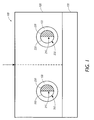
- Fig. 1 shows a cross-section of one exemplary embodiment of an electric paper of this invention;
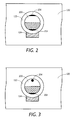
- Fig. 2 shows in greater detail one exemplary embodiment of the gyricon substrate of Fig. 1; and,
- Fig. 3 shows in greater detail one exemplary embodiment of the gyricon substrate having sequestered gyricon balls.
-
- The exemplary embodiments of the systems and methods of this invention are directed to addressing gyricon displays in which magnetic materials are added to the composition of the gyricon balls, and magnetic fields are used to augment the usual electrical addressing fields.
- Fig. 1 shows a cross-sectional view of one exemplary embodiment of a
sheet 100 of electric paper according to the invention. Specifically, as shown in Fig. 1, aconductive base substrate 130 forms the base substrate of thesheet 100 of electric paper. Agyricon substrate 120 is formed over theconductive base substrate 130. Thegyricon substrate 120 includesgyricon balls 200 disposed within the substrate. Eachgyricon ball 200 has twodistinct hemispheres hemisphere gyricon balls 200 are electrically as well as optically anisotropic. - The
gyricon balls 200 are embedded in a sheet of optically transparent material, such as an elastomer layer, that makes up thegyricon substrate 120. Thegyricon substrate 120 also contains a multiplicity ofspheroidal cavities 122 and is permeated by a transparent dielectric fluid, such as a plasticizer. The fluid-filledspheroidal cavities 122 accommodate thegyricon balls 200. In particular, there is onegyricon ball 200 percavity 122 in thegyricon substrate 120. The spheroidal cavities prevent thegyricon balls 200 from migrating within thegyricon substrate 120. Eachgyricon ball 200 can be selectively rotated within in its respective fluid-filledcavity 122 by applying an electric field to present either theblack hemisphere 230 or thewhite hemisphere 220 to an observer viewing the surface of thesheet 100. Thus, applying an electrical field that is adjustable in two dimensions causes the black andwhite hemispheres gyricon balls 200 to appear as image elements, i.e., subpixels or pixels of a display. - As shown in Fig. 1, a
segment line 210 divides thegyricon ball 200 into the twoseparate hemispheres white hemisphere 220 is made using a white pigment. Theblack hemisphere 230 is made using a black pigment. Thegyricon ball 200 can thus either display a white or black face depending on its orientation with respect to a surface of thesheet 100. - Although only two
gyricon balls 200 are shown in Fig. 1, it should be understood that thegyricon substrate 120 may include a very large number ofgyricon balls 200, depending on the resolution desired. Further, although thegyricon balls 200 are described as having two sections, one black hemisphere and one white hemisphere, it should be understood that eachgyricon ball 200 may have more than two segments and may be any two or more-colors, not just black and white. - Each of the black and
white hemispheres gyricon balls 200 are electrically as well as optically anisotropic. Thegyricon balls 200 are embedded in a sheet of optically transparent material, such as an elastomer layer, that makes up thegyricon substrate 120. - Fig. 2 shows in greater detail one exemplary embodiment of the
gyricon substrate 120. As shown in Fig. 2, in the fluid-filledspheroidal cavity 122, there is a stationarymagnetic pad 124 made from high permeability materials, i.e., materials that have ferro-magnetic properties but little residual magnetism when the external field is removed. - The
gyricon ball 200 is made from materials that, for example, develop electrical potentials in contact with the liquid and in the presence of the electrical field, so that one of thehemispheres gyricon ball 200 will develop a different electrical potential than the other side. As shown in Fig. 2, thegyricon ball 200 includes twomagnetic pole pieces 204 that allow thegyricon ball 200 to be located into two different positions by means of the stationarymagnetic pad 124 adjacent to thecavity 122. This allows creation of a strong, engineered threshold for gyricon ball rotation, rather than depending upon the naturally occurring threshold that is neither well understood nor presently controllable. If themagnetic pad 124 is not permanently magnetized, then themagnetic pole pieces 204 must be permanently magnetized. Similarly, if themagnetic pole pieces 204 is not permanently magnetized, then themagnetic pad 124 must be permanently magnetized. - When the
magnetic pole piece 204 in theblack hemisphere 230 of thegyricon ball 200 is adjacent to the stationarymagnetic pad 124 embedded in thecavity wall 122, there will be a strong mechanical force tending to hold thegyricon ball 200 in place. This is because the distance between the magnetized portion of thegyricon ball 200 and the stationarymagnetic pad 124 is very short. This magnetic force will not only cause thegyricon ball 200 to be attached to thecavity wall 122, but it will also require a larger electrical field than otherwise to cause thegyricon ball 200 to start to rotate in thecavity 122. Once thegyricon ball 200 has rotated a short distance, it will experience a much reduced force due to the stationarymagnetic pad 124 and its motion will be dominated by the electrical field. - Thus, if the electrical field initially aligns the
gyricon ball 200 in itscavity 122 in an orientation in which theblack hemisphere 230 is adjacent to the stationarymagnetic pad 124, a strong electrical field will be required to subsequently initiate rotation. By controlling the degree of magnetization of themagnetic pole piece 204 in theblack hemisphere 230 of thegyricon ball 200, the threshold value of electrical field require to initiate ball rotation can be made to satisfy the requirements of passive addressing. It should be appreciated that, if theblack hemisphere 230 is not magnetized, then the degree of magnetization of the stationarymagnetic pad 124 is controlled instead. When thegyricon ball 200 is oriented with thewhite hemisphere 220 adjacent to the stationarymagnetic pad 124, the magnetic pole piece in thewhite hemisphere 220 will be held against thecavity wall 122 by its magnetic attraction to the stationarymagnetic pad 124. - It should be appreciated that the
gyricon ball 200 may be fabricated using any known process. For example, thegyricon ball 200 can be fabricated using a multiple rotating disk apparatus as described in US-A-5,767,826. A magnetic pigment similar to that used in manufacturing magnetic tapes, for example, may be used in themagnetic pole pieces 204, either alone or in combination with other pigments. Thesemagnetic pole pieces 204 would be permanently magnetized with thegyricon ball 200 in a given orientation, possibly in flight from the disk during their manufacture. - The stationary
magnetic pad 124 in the wall of thecavity 122 may be fabricated by mixing themagnetized gyricon ball 200 with a high permeability powder, so that the particles would cluster around the magnetized portion of theblack hemisphere 230. Surplus particles would be removed and thegyricon ball 200 would be mixed with a liquid resin that would later be cured into a tough silicone elastomer. The high permeability particles would now be incorporated into the elastomer matrix in the vicinity of the magnetized portion of thegyricon ball 200. - In accordance with various exemplary embodiments of this invention, the
gyricon ball 200 is made from a polyethylene plastic as described in US-A-5,717,514. Thewhite hemisphere 220 is made from this plastic, with titanium dioxide dispersed in it. Theblack hemisphere 230 is made from this same plastic, with a black pigment dispersed in it, as well as a chemical called a charging agent. - As shown in Fig. 2, the
gyricon ball 200 contained in theelastomer cavity 122 is provided with twomagnetic pole pieces 204. As shown in Fig. 2, themagnetic pad 124 latches thegyricon ball 200 into one of two stable rotational positions via the twomagnetic pole pieces 204. Themagnetic pole piece 204 located in thewhite hemisphere 220, which may be dark in color, may subtend a substantial part of the visible portion of thewhite hemisphere 220 of thegyricon ball 200. This would greatly reduce the whiteness and the contrast of the gyricon display. - It is desirable to sequester the
magnetic pole piece 204 located in thewhite hemisphere 220 of thisgyricon ball 200 without substantially moving themagnetic pole piece 204 from its intended position. This can be done by causing themagnetic pole piece 204 to be covered with a quantity of white pigmented plastic. This can be done by causing the white pigmented plastic of thewhite hemisphere 220 to engulf the black magnetic pigmented plastic of themagnetic pole piece 204. - It is further desirable to increase the number of pigment combinations that can be generally used to fabricate liquid beads using a spinning disk as described in US-A-5,767,826, for example, and before the liquid beads have had a chance to cool and solidify into gyricon balls. It is to be appreciated that some combinations of pigments will result in the production of liquid beads in which one of the pigmented plastics has partially or completely flowed over and engulfed the other pigmented plastic during the gyricon ball making process.
- In obtaining liquid beads used in the fabrication of the gyricon balls, many materials packages yield liquid beads in which one pigmented plastic will tend to flow over another pigmented plastic. This may result in liquid beads in which one color hemisphere will be larger than the other color hemisphere. Accordingly, one color may be completely submerged beneath the other color, so that a liquid bead appears to consist of a single color of plastic. This process is called engulfing which may occur after a liquid bead is formed from the spinning disk, and before the liquid bead has had a chance to cool and solidify into the gyricon ball.
- Engulfing may occur due to an instability in the liquid bead after it is formed, which may include hydrodynamic instability. Engulfing may be reduced by operating the gyricon ball making apparatus, and thus the molten pigmented plastics, at lower temperatures. As a liquid bead moves through the air from the breakup of the ligament extending from the edge of the disk, the liquid bead cools by exchanging heat with the ambient air. Thus, the processes responsible for engulfing are shortened by the faster freezing of the liquid ball components.
- In the various exemplary embodiments of the systems and methods of this invention, engulfing and sequestering the
magnetic pad 124 on thewhite hemisphere 220 of thegyricon ball 200 is provided. Themagnetic pads 124 are made by dispersing magnetic pigments into the polyethylene plastic. The addition of aluminum octoate to either thewhite hemisphere 220 of thegyricon ball 200 or theblack hemisphere 230 of thegyricon ball 200 will cause the pigmented plastic on that side of thegyricon ball 200 to attempt to envelope the pigmented plastic on parts of thegyricon ball 200 that does not have aluminum octoate added during the ball making process. Hence, adding aluminum octoate to the white pigmented plastic will cause it to envelope themagnetic pad 124 on thewhite hemisphere 220 of thegyricon ball 200, as shown in Fig. 3. Themagnetic pad 124 so engulfed will now be sequestered under the surface of the gyricon ball, greatly reducing its deleterious effects on the optical properties of the gyricon display. - It should be appreciated that it may also be necessary to add aluminum octoate to the
black hemisphere 230 of thegyricon ball 200 to nullify the attempt of thewhite hemisphere 220 of thegyricon ball 200 to engulf theblack hemisphere 230 of thegyricon ball 200. In this manner, themagnetic pad 124 will remain localized near the poles of thegyricon ball 200, but submerged and not very visible. - If aluminum octoate is added to a first pigmented polyethylene liquid and the liquid is subsequently used to make liquid beads in conjunction with a second pigmented polyethylene liquid, and if the first liquid without the aluminum octoate added has a tendency to engulf the second liquid then with the aluminum octoate added, then there is substantially less tendency for engulfing to occur. As still more aluminum octoate is added, there is even less tendency for engulfing to occur. As even more aluminum octoate is added, a tendency develops for the second liquid to engulf the first liquid.
- For example, gyricon balls made using 20% R104 titanium dioxide by DuPont dispersed in Polywax 1000 polyethylene (by Baker Petrolite Corp.) for the white hemisphere of the gyricon ball and 2.5% Columbian Chemicals #7006 carbon black and 1% 5175 (an acetate ester by the Baker Petrolite Corp.) dispersed in Polywax 1000 for the black hemisphere of the gyricon ball may suffer severe engulfing of the black hemisphere of the gyricon ball by the white pigmented plastic. In one exemplary embodiment, adding 0.2% aluminum octoate to the black hemisphere of the gyricon ball may reduce or eliminate the white engulfing. Increasing the amount of aluminum octoate added to the black hemisphere of the gyricon ball to 1% may cause severe engulfing of the white side of the ball by the black pigmented plastic. Hence, the addition of aluminum octoate may effectively control the engulfing discussed.
- In various exemplary embodiments, aluminum octoate may be used to increase viscosity or as a gelling agent. It is to be appreciated that, with various pigmented polyethylene systems, a lower viscosity liquid will tend to engulf a higher viscosity liquid during the liquid bead making process.
- It should be appreciated that though aluminum octoate is discussed in the above exemplary embodiments, other chemicals may also be used which have an effect on engulfing. Such chemicals include but are limited to the aluminum stearates.
- In the above exemplary embodiments, aluminum octoate is applied to provide a chemical control of engulfing. Thus, a method of at least partially controlling the engulfing of one liquid by another during the production of gyricon balls is obtained.
- It should be appreciated that though gyricon balls are discussed in the above exemplary embodiments, this invention is not limited to gyricon balls. That is, the methods and apparatus may include the production of gyricon bichromal balls as described above, and other gyricon balls generally referred to as optically transmissive balls. The optically transmissive balls are described in US-A-5,739,801.
- The invention has been described in relation to a gyricon display. However, the principles it illustrates can be equally well applied to many other high impedance displays, such as certain liquid crystal displays and electrophoretic displays.
Claims (9)
- A display device, comprising:a gyricon layer comprising a plurality of cavities, each cavity having a magnetic pad positioned therein; anda plurality of gyricon balls respectively disposed in the cavities of the gyricon layer, each gyricon ball comprising at least a first portion of a first pigment with a first magnetic pole piece provided therein, and a second portion of a second pigment with a second magnetic pole piece provided therein, wherein said first magnetic pole piece is sequestered by the first pigment.
- The display device of claim 1, wherein said first portion comprises aluminum octoate.
- A device according to claim 1 or claim 2, wherein said first pigment engulfs said second pigment.
- A display device, comprising:a layer comprising a plurality of cavities; anda plurality of gyricon balls disposed in the cavities of the layer, said gyricon balls comprising aluminum octoate.
- The method of claim 4, wherein said gyricon balls comprising aluminum stearate.
- A method of forming a display device, comprising:forming a gyricon layer comprising a plurality of cavities, each cavity having a magnetic pad positioned therein; andrespectively disposing a plurality of gyricon balls in the cavities of the gyricon layer, each gyricon ball comprising at least a first portion of a first pigment with a first magnetic pole piece provided therein, and a second portion of a second pigment with a second magnetic pole piece provided therein, wherein said first magnetic pole piece is sequestered by the first pigment.
- The method of claim 6, wherein said first pigment comprises aluminum octoate.
- A method according to claim 6 or claim 7, wherein said first pigment engulfs said second pigment.
- The method of claim 8, wherein said first pigment engulfs said second pigment before solification.
Applications Claiming Priority (2)
| Application Number | Priority Date | Filing Date | Title |
|---|---|---|---|
| US09/749,560 US6480321B2 (en) | 2000-12-28 | 2000-12-28 | Controlling engulfing and sequestering magnetic pads |
| US749560 | 2000-12-28 |
Publications (3)
| Publication Number | Publication Date |
|---|---|
| EP1220009A2 true EP1220009A2 (en) | 2002-07-03 |
| EP1220009A3 EP1220009A3 (en) | 2003-06-04 |
| EP1220009B1 EP1220009B1 (en) | 2006-02-01 |
Family
ID=25014245
Family Applications (1)
| Application Number | Title | Priority Date | Filing Date |
|---|---|---|---|
| EP01310676A Expired - Lifetime EP1220009B1 (en) | 2000-12-28 | 2001-12-20 | Controlling engulfing and sequestering magnetic pads |
Country Status (5)
| Country | Link |
|---|---|
| US (1) | US6480321B2 (en) |
| EP (1) | EP1220009B1 (en) |
| JP (1) | JP4081268B2 (en) |
| CA (1) | CA2366053C (en) |
| DE (1) | DE60116978T2 (en) |
Cited By (1)
| Publication number | Priority date | Publication date | Assignee | Title |
|---|---|---|---|---|
| WO2013056621A1 (en) * | 2011-10-20 | 2013-04-25 | 京东方科技集团股份有限公司 | Electrophoresis display device |
Families Citing this family (1)
| Publication number | Priority date | Publication date | Assignee | Title |
|---|---|---|---|---|
| US8077142B2 (en) * | 2006-09-27 | 2011-12-13 | Tred Displays Corporation | Reflective, bi-stable magneto optical display architectures |
Citations (4)
| Publication number | Priority date | Publication date | Assignee | Title |
|---|---|---|---|---|
| US5717514A (en) * | 1995-12-15 | 1998-02-10 | Xerox Corporation | Polychromal segmented balls for a twisting ball display |
| US5767826A (en) * | 1995-12-15 | 1998-06-16 | Xerox Corporation | Subtractive color twisting ball display |
| US5894367A (en) * | 1996-09-13 | 1999-04-13 | Xerox Corporation | Twisting cylinder display using multiple chromatic values |
| EP1005008A2 (en) * | 1998-11-25 | 2000-05-31 | Xerox Corporation | Gyricon displays utilizing magnetic addressing and latching mechanisms |
Family Cites Families (4)
| Publication number | Priority date | Publication date | Assignee | Title |
|---|---|---|---|---|
| US5739801A (en) | 1995-12-15 | 1998-04-14 | Xerox Corporation | Multithreshold addressing of a twisting ball display |
| US6067185A (en) * | 1997-08-28 | 2000-05-23 | E Ink Corporation | Process for creating an encapsulated electrophoretic display |
| AU6293499A (en) * | 1998-10-07 | 2000-04-26 | E-Ink Corporation | Capsules for electrophoretic displays and methods for making the same |
| US6243058B1 (en) * | 1999-03-25 | 2001-06-05 | Xerox Coporation | Tribo-addressed and tribo-suppressed electric paper |
-
2000
- 2000-12-28 US US09/749,560 patent/US6480321B2/en not_active Expired - Fee Related
-
2001
- 2001-12-20 DE DE60116978T patent/DE60116978T2/en not_active Expired - Lifetime
- 2001-12-20 CA CA002366053A patent/CA2366053C/en not_active Expired - Fee Related
- 2001-12-20 EP EP01310676A patent/EP1220009B1/en not_active Expired - Lifetime
- 2001-12-25 JP JP2001391092A patent/JP4081268B2/en not_active Expired - Fee Related
Patent Citations (4)
| Publication number | Priority date | Publication date | Assignee | Title |
|---|---|---|---|---|
| US5717514A (en) * | 1995-12-15 | 1998-02-10 | Xerox Corporation | Polychromal segmented balls for a twisting ball display |
| US5767826A (en) * | 1995-12-15 | 1998-06-16 | Xerox Corporation | Subtractive color twisting ball display |
| US5894367A (en) * | 1996-09-13 | 1999-04-13 | Xerox Corporation | Twisting cylinder display using multiple chromatic values |
| EP1005008A2 (en) * | 1998-11-25 | 2000-05-31 | Xerox Corporation | Gyricon displays utilizing magnetic addressing and latching mechanisms |
Cited By (2)
| Publication number | Priority date | Publication date | Assignee | Title |
|---|---|---|---|---|
| WO2013056621A1 (en) * | 2011-10-20 | 2013-04-25 | 京东方科技集团股份有限公司 | Electrophoresis display device |
| US9025236B2 (en) | 2011-10-20 | 2015-05-05 | Boe Technology Group Co., Ltd. | Electrophoretic display device |
Also Published As
| Publication number | Publication date |
|---|---|
| DE60116978D1 (en) | 2006-04-13 |
| CA2366053A1 (en) | 2002-06-28 |
| JP4081268B2 (en) | 2008-04-23 |
| EP1220009A3 (en) | 2003-06-04 |
| US6480321B2 (en) | 2002-11-12 |
| EP1220009B1 (en) | 2006-02-01 |
| CA2366053C (en) | 2007-07-03 |
| JP2002258331A (en) | 2002-09-11 |
| DE60116978T2 (en) | 2006-07-27 |
| US20020085263A1 (en) | 2002-07-04 |
Similar Documents
| Publication | Publication Date | Title |
|---|---|---|
| EP0913804B1 (en) | A twisting cylinder display using multiple chromatic values | |
| US6211998B1 (en) | Magnetic unlatching and addressing of a gyricon display | |
| US6147791A (en) | Gyricon displays utilizing rotating elements and magnetic latching | |
| US6262707B1 (en) | Gyricon displays utilizing magnetic addressing and latching mechanism | |
| US7280094B2 (en) | Bistable electro-optic display, and method for addressing same | |
| US5922268A (en) | Method of manufacturing a twisting cylinder display using multiple chromatic values | |
| US6097531A (en) | Method of making uniformly magnetized elements for a gyricon display | |
| US5751268A (en) | Pseudo-four color twisting ball display | |
| US6197228B1 (en) | Method of making a gyricon display using magnetic latching | |
| CA2249098C (en) | A method of manufacturing a twisting cylinder display using multiple chromatic values | |
| US6542283B1 (en) | Gyricon displays utilizing magnetic elements and magnetic trapping | |
| US6110538A (en) | Method of making a gyricon display using magnetic latching | |
| US6480321B2 (en) | Controlling engulfing and sequestering magnetic pads | |
| US6441946B1 (en) | Swollen gyricon displays and method of making same | |
| US6480322B2 (en) | Method of improving the respondability of moveable structures in a display | |
| US6174153B1 (en) | Apparatus for making uniformly magnetized elements for a gyricon display | |
| US6362915B1 (en) | Bichromal beads having crystalline materials therein | |
| US7193769B2 (en) | Two particle electophoretic systems, electronic displays including two particle electophoretic systems, and methods for producing the two particle electophoretic systems | |
| JP4398621B2 (en) | Rotating element sheet material, method for addressing rotating element sheet material, and method for creating rotating element sheet material | |
| CA2289382C (en) | Gyricon displays utilizing magnetic addressing and latching mechanisms | |
| US6496298B1 (en) | Bichromal beads having charge adjuvants therein | |
| US6251329B1 (en) | Method of making a gyricon display using magnetic latching | |
| US7432942B2 (en) | Electric display media | |
| CA2245130C (en) | Twisting cylinder display using multiple chromatic values | |
| US7382520B2 (en) | Charge control agents in display media |
Legal Events
| Date | Code | Title | Description |
|---|---|---|---|
| PUAI | Public reference made under article 153(3) epc to a published international application that has entered the european phase |
Free format text: ORIGINAL CODE: 0009012 |
|
| AK | Designated contracting states |
Kind code of ref document: A2 Designated state(s): AT BE CH CY DE DK ES FI FR GB GR IE IT LI LU MC NL PT SE TR |
|
| AX | Request for extension of the european patent |
Free format text: AL;LT;LV;MK;RO;SI |
|
| PUAL | Search report despatched |
Free format text: ORIGINAL CODE: 0009013 |
|
| AK | Designated contracting states |
Designated state(s): AT BE CH CY DE DK ES FI FR GB GR IE IT LI LU MC NL PT SE TR |
|
| AX | Request for extension of the european patent |
Extension state: AL LT LV MK RO SI |
|
| 17P | Request for examination filed |
Effective date: 20031204 |
|
| AKX | Designation fees paid |
Designated state(s): DE FR GB |
|
| 17Q | First examination report despatched |
Effective date: 20040323 |
|
| GRAP | Despatch of communication of intention to grant a patent |
Free format text: ORIGINAL CODE: EPIDOSNIGR1 |
|
| GRAS | Grant fee paid |
Free format text: ORIGINAL CODE: EPIDOSNIGR3 |
|
| GRAA | (expected) grant |
Free format text: ORIGINAL CODE: 0009210 |
|
| AK | Designated contracting states |
Kind code of ref document: B1 Designated state(s): DE FR GB |
|
| REG | Reference to a national code |
Ref country code: GB Ref legal event code: FG4D |
|
| REF | Corresponds to: |
Ref document number: 60116978 Country of ref document: DE Date of ref document: 20060413 Kind code of ref document: P |
|
| ET | Fr: translation filed | ||
| PLBE | No opposition filed within time limit |
Free format text: ORIGINAL CODE: 0009261 |
|
| STAA | Information on the status of an ep patent application or granted ep patent |
Free format text: STATUS: NO OPPOSITION FILED WITHIN TIME LIMIT |
|
| 26N | No opposition filed |
Effective date: 20061103 |
|
| PGFP | Annual fee paid to national office [announced via postgrant information from national office to epo] |
Ref country code: FR Payment date: 20101224 Year of fee payment: 10 |
|
| PGFP | Annual fee paid to national office [announced via postgrant information from national office to epo] |
Ref country code: GB Payment date: 20101215 Year of fee payment: 10 |
|
| PGFP | Annual fee paid to national office [announced via postgrant information from national office to epo] |
Ref country code: DE Payment date: 20101215 Year of fee payment: 10 |
|
| GBPC | Gb: european patent ceased through non-payment of renewal fee |
Effective date: 20111220 |
|
| REG | Reference to a national code |
Ref country code: FR Ref legal event code: ST Effective date: 20120831 |
|
| REG | Reference to a national code |
Ref country code: DE Ref legal event code: R119 Ref document number: 60116978 Country of ref document: DE Effective date: 20120703 |
|
| PG25 | Lapsed in a contracting state [announced via postgrant information from national office to epo] |
Ref country code: DE Free format text: LAPSE BECAUSE OF NON-PAYMENT OF DUE FEES Effective date: 20120703 Ref country code: GB Free format text: LAPSE BECAUSE OF NON-PAYMENT OF DUE FEES Effective date: 20111220 |
|
| PG25 | Lapsed in a contracting state [announced via postgrant information from national office to epo] |
Ref country code: FR Free format text: LAPSE BECAUSE OF NON-PAYMENT OF DUE FEES Effective date: 20120102 |