EP1221280B2 - Device to monitor the function of a working machine - Google Patents
Device to monitor the function of a working machine Download PDFInfo
- Publication number
- EP1221280B2 EP1221280B2 EP01130579A EP01130579A EP1221280B2 EP 1221280 B2 EP1221280 B2 EP 1221280B2 EP 01130579 A EP01130579 A EP 01130579A EP 01130579 A EP01130579 A EP 01130579A EP 1221280 B2 EP1221280 B2 EP 1221280B2
- Authority
- EP
- European Patent Office
- Prior art keywords
- sensor
- machine
- signal
- computer device
- comparison value
- Prior art date
- Legal status (The legal status is an assumption and is not a legal conclusion. Google has not performed a legal analysis and makes no representation as to the accuracy of the status listed.)
- Expired - Lifetime
Links
Images

Classifications
-
- A—HUMAN NECESSITIES
- A01—AGRICULTURE; FORESTRY; ANIMAL HUSBANDRY; HUNTING; TRAPPING; FISHING
- A01D—HARVESTING; MOWING
- A01D41/00—Combines, i.e. harvesters or mowers combined with threshing devices
- A01D41/12—Details of combines
- A01D41/127—Control or measuring arrangements specially adapted for combines
Definitions
- the invention relates to a self-propelled, attached or towed agricultural working machine according to the preamble of claim 1 and a method for monitoring the function of a self-propelled, mounted or towed agricultural working machine according to the preamble of claim 11.
- a device for determining the natural vibration causing parameter is described, which is to assist in the construction of rotating work organs, such as threshing or chopping drums.
- the drum to be examined is attached to a rotary or translational oscillator and set in motion.
- the vibration behavior of the drums outside the machine is examined, which can not give the operator of the machine at work support.
- BG 33 743 a device for the physical-mechanical examination of working elements of a grape picker is described. Vibrations of the device are recorded and displayed on an oscilloscope.
- the US 4 574 633 A describes a monitoring device for a cutting machine tool.
- noise courses for properly working tools are stored.
- the emitted by the tool in each case used sounds are using a sensor and supplied to an analog comparator circuit, which compares them with the recalled from the memory, converted by a digital-to-analog converter into analog values signal curves of the proper tool.
- the waveforms are retrieved from the memory depending on the tool selected.
- the comparator determines a difference of the envelopes of the two signals and in case of exceeding a threshold an error signal is given.
- the US 6,116,089 A describes a rotating machine for conveying, among other things for forest products.
- a driven roller is associated with an accelerometer whose signals are fed to a comparison circuit. It compares normal and current vibration profiles of the machine and outputs an error message if the measured spectrum does not match the normal spectrum, which may be due to faulty weld seams of the roller.
- a field forage harvester with a cutterhead and several feed rollers is described.
- a microphone is arranged to receive sound waves emitted by the counter-blade.
- the microphone is connected to an electronic control unit with a microprocessor, which in turn controls an adjustment of the counter-blade and detects any contact of the counter-blade with the cutterhead on the basis of the signals of the microphone.
- the microphone and the control unit can serve in the harvesting process, possibly to detect bouncing stones against the feed roller and stop the feed roller automatically in such a case. Whether a counter cutting adjustment or a harvesting process takes place, the control unit recognizes by the position of a switch.
- the US 4 302 813 A describes a monitoring device of a large rotating machine in the form of a steam turbine and a generator connected thereto. The speeds and vibrations are detected and are used for automatic detection of any unwanted vibrations and an adapted control of the startup of the steam turbine.
- the EP 0 793 939 A refers to a dishwasher with an acoustic sensor, whose output signal with a processor below is checked to see if water enters and a spray arm turns correctly. Depending on the detected noise, the dishwasher is automatically controlled
- the GB 2 348 998 A describes an alarm system for agricultural machinery based on detecting noises and reproducing sounds in the cab. It is also proposed to detect errors by means of speed measurements or other sensors and to emit acoustic signals dependent on the respective error.
- the object underlying the invention is seen to provide an improved device for monitoring the function of an agricultural work machine, which allows early detection of errors.
- An agricultural working machine is equipped with a computer device which is supplied with a signal from at least one sensor containing information about a noise caused by the movement or vibration of an element of the working machine.
- the computing device uses the signal and a comparison value to provide a signal value that includes information about whether the work machine is operating properly or if there is an error.
- the computer device is operable to assign the signal provided by the at least one sensor to an element of the work machine. It is set up to give an error message if the signal from the sensor indicates a fault of the working machine.
- An error message can be output if a parameter derived from the signal of the sensor lies outside the predetermined value of the parameter outside of a specific interval, in particular deviates from the comparison value by an amount that is greater than a threshold value.
- the parameter is in particular the frequency and / or amplitude of a vibration.
- an error signal is not necessarily output only when an oscillation is stronger than intended by a first threshold value, but is also weaker by a second threshold (possibly different from the first threshold value), since a too weak oscillation sensed by the sensor can also cause a Indication of an error contain.
- An element is assigned the signal of a sensor when the movement frequency is approximately known. The computer device determines based on the frequency of a signal component whose source, and assigns this signal component to the respective element. In the event of a fault, the element is thus easily verifiable and can be brought to the display.
- the element is associated with a speed sensor which detects the rotational frequency of the element.
- speed sensors are measured electronically in modern machines for major components by default. Therefore, part of the required information can already be read from the data bus.
- the rotational speeds or movement frequencies of all preceding and following moving assemblies are known about the known gear ratios throughout the drive system.
- the slip can be calculated with. If necessary, additional speed sensors can or must be installed.
- the signal of the rotational speed sensor is supplied to the computer device, which assigns to the element the signal components of the motion and / or vibration sensor, which correlate with the rotational frequency measured by the rotational speed sensor.
- the monitoring device replaced as it were the ear of the operator located in the soundproof cabin.
- evidence of wear or cracks, insufficient lubrication of bearings, defective bearings, fractures or deformations of components, solved or broken screw, welded joints or other compounds or imbalances in moving elements of the working machine can be obtained at a very early stage.
- Loosening connections, such as nuts and bolts, lead to changes in the vibration behavior, and corresponding measures can be initiated based on the signal value provided by the computer device, even before any damage occurs.
- the signal of the sensor and the comparison value for generating the signal value;
- it is preferred to derive from the signal of the sensor a parameter which serves with the comparison value for generating the signal value.
- a comparison is made between the signal (or a parameter derived therefrom) and the comparison value.
- other mathematical operations for generating the signal value are also applicable.
- the sensor is arranged to detect the noise generated by the movement and / or vibration of a driven member of the work machine. He can thus interact directly with the driven element, and detect its sounds in any way, such as mechanical, optical or inductive.
- the driven element is preferably a Gut Rushingelement and / or a Gutbearbeitungselement, z. B. a chopper or threshing drum.
- the same or a different sensor may also noise of a driven or non-driven element, for.
- As the screen box a side wall of a combine or a supporting element capture. Such an element generates in case of error other sounds than normal, which can be detected by the sensor.
- any type of sensor or sensor used to record structure-borne noise, airborne sound, mechanical vibrations or any other physical variable directly or indirectly related to these vibrations may be used for direct or indirect signal acquisition are suitable or are, such as single or multi-dimensional accelerometer, body and / or airborne microphones.
- the sensor used is thus preferably an acoustic sensor (microphone) or a motion sensor (vibration sensor, for example structure-borne sound sensor), which has a Information about the acceleration acting on it or its speed or position supplies. But also all forms of sensors for compressive and / or tensile stresses and / or vibrations are usable.
- the sensor can thus be arranged at a distance from the monitored element on the working machine, wherein the acoustic oscillation of the element is acoustically or mechanically transmitted to the sensor, for example by the chassis or other the element to be monitored bearing or directly or indirectly mechanically connected parts of the working machine.
- the comparison values do not necessarily have to be values of a fault-free work machine, since it is also conceivable to store values that are of a work machine with a known defect correspond. In this case, an error can be easily identified. Of course, it is also possible to compare the values measured by the sensor (or parameters derived therefrom) with a plurality of comparison values which correspond to machines with known errors.
- the assignment of a signal to an element can be done in such a way that the respective element is determined by the position of a sensor, when the latter is set up to detect only the movement of a single element.
- a suitable motion sensor can detect the movement of only a rotary conveyor or a Gutbearbeitungstrommel.
- a comparison value the value of a defective machine.
- a stored parameter measured in the event of defective storage could be compared with the measured parameter, which permits unproblematic proof of defective storage.
- a comparison can be made with comparison values which correspond to defective machines with specific errors, which allows a simple and rapid recognition of the error.
- the comparison value of the signal may be permanently stored, e.g. B. stored in a ROM.
- a static comparison value can lead to incorrect error messages. New machines are not identical when running off the line. Dimensional tolerances of components, tolerances in the tightening torques of screwed connections, material tolerances and much more cause differences in the nominal noise of a machine as good as new. It is therefore preferable to record the signals from the sensors in a fault-free (in particular in the respective) machine, for example, at the beginning of a work process and store as a comparison value in a memory connected to the computer unit.
- the computing unit may also include a neural network capable of self-learning what the spectrum of a working machine will look like.
- the sensors can also support quality control during production.
- the monitoring device does not necessarily have to be always active and monitor the work machine for damage. It may also be sufficient to occasionally analyze the noise spectrum of the work machine, for example, turning at the end of a field.
- the monitoring device can in this embodiment by means of a (usually existing) Means are connected to detect the position of the working machine, such as a GPS device.
- the monitoring device is used on agricultural machines.
- self-propelled machines such as tractors, combine harvesters, forage harvesters and cotton pickers are mentioned.
- trailed or cultivated machines for example on harvest attachments such as corn pickers, maize bits or cutting units.
- Fertilizer spreaders and mounted, towed or self-propelled sprayers can also be equipped with the monitoring device.
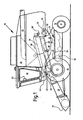
- FIG. 1 shows an agricultural combine 10 with a chassis 12 and extending therefrom bottom wheels 14, by way of example the invention will be explained.
- a crop gathering device 16 in the form of a header is used to pick up crop material and feed it to an inclined conveyor 18.
- the crop is fed by the feeder 18 of a guide drum 20.
- the guide drum 20 forwards the crop upward through an inlet transition region 22 to an axial separation device 24.
- the Axialtrennvoriques 24 threshes and separates the harvested good. Grain and chaff fall through grates at the bottom of the axial separator 24 into a cleaning system 26.
- the cleaning system 26 removes the chaff and feeds the clean grain to a grain elevator (not shown).
- the grain elevator deposits the clean grain in a grain tank 28.
- the clean grain in the grain tank 28 may be unloaded by a discharge auger 30 into a trailer or truck.
- Threshed straw removed from the grain is fed out of the axial separation device 24 through an outlet 32 to a discharge drum 34.
- the axial separation device 24 comprises a cylindrical rotor housing 38 and a rotor 39 arranged in the rotor housing 38.
- the discharge drum 34 ejects the straw at the rear end of the combine 10.
- the operation of the combine harvester 10 takes place from a driver's cab 36.
- a computer 46 is arranged, which is connected to various sensors:
- a sensor 48 is mounted on the axial separator 24 and senses vibrations of the rotor housing 38.
- a sensor 50 is attached to the chassis 12, which detects vibrations of the supporting parts of the chassis 12 caused by it.
- a sensor 54 is arranged on the chassis 12.
- a speed sensor 58 detects the rotational speed of the rotor 39 inductively by a permanent magnet 60 mounted on the rotor 39.
- a sensor 56 is mounted on the chassis 12 above the cleaning system 26.
- the sensors 48, 50, 54 and 56 are per se known sensors which are arranged to generate signals which contain information about the sound waves picked up by the sensors 48, 50, 54 and 56. In particular, these may be acoustic or acceleration sensors.
- the sensor 48 primarily (mainly) provides information about the movement of the rotor housing 38 and thus vibrations caused by the rotating rotor 39.
- the sensor 50 primarily provides information about vibrations of the chassis 12 caused by the delivery drum 34.
- the sensor 54 primarily provides information about the vibrations caused by the fan 52.
- the sensor 56 provides information about the vibrations of the chassis caused by all the moving elements of the combine 10.
- the sensors 48, 50, 54, 56 and 58 are electrically (or optically) connected to the computer 46, preferably via a bus line.
- the computer 46 digitizes the analog signals of the sensors, evaluates them and gives the operator in the driver's cab 36 on a display device 62 an error message when the error of the combine harvester 10 can be seen from the signals.
- step 102 the signals of the sensors 48, 50, 54, 56 and 58 are recorded for a certain time T, for example over 10 seconds.
- T the voltage profile of the signals supplied by the sensors 48, 50, 54, 56 and 58 is stored by the computer device as a function of time.
- a frequency spectrum is calculated from the stored signal values supplied by the sensors 48, 50, 54, 56 and 58 by a Fourier analysis or transformation. Different frequencies are assigned an amplitude value, wherein also negative, a phase information containing frequency values are possible. Such a frequency spectrum is in FIG. 4 indicated.
- maxima of the amplitudes are detectable, as in FIG. 4 recognizable.
- the width of the maxima is usually dependent on the time T; it becomes smaller the longer T is.
- the individual maxima can be assigned to the movements and / or vibrations of the elements of the combine harvester 10.
- the rotational frequency of the rotor 39 can unproblematically determine the computer device by the signals of the rotational speed sensor 58. Signals with components whose frequency is at multiples of the rotational frequency of the rotor 39 can thus be assigned to the rotor 39.
- the remaining elements of the combine harvester 10 can be assigned the components via their at least approximately known frequencies and / or by the position of the respective sensor.
- the computer device 46 After step 104, the computer device 46 thus has frequency spectra of the four sensors 48, 50, 54 and 56, which are examined one after the other. Between the conditional by periodic movements of Gutrion- and Gutbearbeitungs institute of the combine 10 maxima a stochastic surface is present, which is at least partially due to the flow of material.
- the signals of the sensors 48, 50, 54 and 56 can thus be divided into periodic, by the machine (combine harvester 10) conditional shares and stochastic, due to the crop flow shares, which are distinguishable and separately analyzable in this way.
- FIG. 2 is reproduced for simplicity only the investigation of a single frequency spectrum, z. B. the sensor 56.
- the frequency spectra of the other sensors are examined in an analogous manner.
- step 106 the first maximum of the frequency spectrum is searched.
- step 108 follows, in which it is examined whether the difference between the amplitude of the maximum and a stored comparison value is greater than a first defined, stored threshold value (threshold 1).
- the first threshold is negative. It is therefore queried whether the oscillation amplitude is significantly greater than the comparison value.
- a second stored threshold threshold 2. If the amplitude minus the setpoint value is greater than the second threshold value, this indicates that the oscillation is too large, and the amplitude minus the setpoint value is less than the first threshold value, this indicates an improper drive of the element. B. may be caused by a defective drive belt. In both cases, an error message is issued in step 110.
- step 112 is followed, in which it is examined whether the absolute value of the difference between the frequency of the maximum (f max ) and a stored nominal frequency (f soll ) is greater than a threshold value. If the actual frequency deviates too far from the nominal frequency, an error could be present, so that an error message is also issued in step 114. On the basis of the position of the maximum and / or the position of the sensor from which the frequency spectrum causing the error message originates, an indication can be given in step 110 and step 114 on the display device 62, in which element of the combine 10 there may be an error. Also in step 112, a lower and upper threshold different from the lower one could be used for the allowed range of the deviation from the target frequency, analogous to step 108.
- step 112 shows that the frequency of the maximum at least approximately coincides with the comparison value
- step 116 follows, in which it is queried whether all maxima have been checked. If so, step 102 follows again. Otherwise, step 118 follows, in which the next maximum is searched, followed by step 108 again.
- the monitoring device constructed from the sensors 48, 50, 52, 54 and 58 and the computing device 46 allows for easy monitoring of the combine 10 for unexpectedly moving elements and thus early detection of any errors.
Description
Die Erfindung betrifft eine selbstfahrende, angebaute oder gezogene landwirtschaftliche Arbeitsmaschine nach dem Oberbegriff des Anspruchs 1 und ein Verfahren zur Überwachung der Funktion einer selbstfahrenden, angebauten oder gezogenen landwirtschaftlichen Arbeitsmaschine nach dem Oberbegriff des Anspruchs 11.The invention relates to a self-propelled, attached or towed agricultural working machine according to the preamble of
Zum Schutz vor Umgebungseinflüssen werden landwirtschaftliche Maschinen mit immer aufwändigeren, schalldichten Kabinen ausgestattet. Auf verschiedenen Wegen wird zwar versucht, dem Bediener ein Bild über den Maschinenzustand zu geben, wie beispielsweise durch Warnanzeigen für Drehzahlen und den Hydraulikflüssigkeitsdruck. Durch die schallisolierende Kabine kann der Bediener aber die Überwachungs- und Kontrollfunktion für die Maschine schlechter als bei einer Maschine mit offenem Arbeitsplatz aufnehmen, da er eventuell von nicht korrekt arbeitenden Teilen der Maschine verursachte Geräusche weniger gut wahrnehmen kann.To protect against environmental influences, agricultural machines are equipped with increasingly sophisticated, sound-proof cabins. Although various attempts are made to give the operator an idea of the machine's condition, such as speed warnings and hydraulic fluid pressure. However, the sound-insulating cab can make the machine's monitoring and control function worse than with an open-work machine, as it may be less able to perceive any noise caused by improperly working parts of the machine.
In der
In der BG 33 743 ist eine Einrichtung zur physikalisch-mechanischen Untersuchung von Arbeitselementen eines Traubenpflückers beschrieben. Schwingungen des Geräts werden erfasst und auf einem Oszillographen zur Anzeige gebracht.In BG 33 743 a device for the physical-mechanical examination of working elements of a grape picker is described. Vibrations of the device are recorded and displayed on an oscilloscope.
Außerdem ist es bekannt, Mähdrescher mit Schwingungsaufnehmern zu versehen, die Verlustkörner erfassen. Die Signale der Schwingungsaufnehmer werden ausgewertet und zur Anzeige des Verlustanteils herangezogen. Dadurch wird aber keine Überwachung beweglicher Elemente des Mähdreschers ermöglicht.It is also known to provide combine harvester with vibration sensors that detect lost grains. The signals of the vibration sensors are evaluated and used to display the loss component. However, this does not allow monitoring of moving elements of the combine.
Die
Die
In der als gattungsbildend angesehenen
Die
Die
Die
Die der Erfindung zugrunde liegende Aufgabe wird darin gesehen, eine verbesserte Einrichtung zur Überwachung der Funktion einer landwirtschaftlichen Arbeitsmaschine zur Verfügung zu stellen, die eine frühzeitige Erkennung von Fehlern ermöglicht.The object underlying the invention is seen to provide an improved device for monitoring the function of an agricultural work machine, which allows early detection of errors.
Diese Aufgabe wird erfindungsgemäß durch die Lehre der Patentansprüche 1 und 11 gelöst, wobei in den weiteren Patentansprüchen Merkmale aufgeführt sind, die die Lösung in vorteilhafter Weise weiterentwickeln.This object is achieved by the teaching of
Eine landwirtschaftliche Arbeitsmaschine ist mit einer Rechnereinrichtung ausgestattet, die von wenigstens einem Sensor mit einem Signal versorgt wird, das eine Information über ein Geräusch enthält, das durch die Bewegung bzw. Schwingung eines Elements der Arbeitsmaschine verursacht wird. Die Rechnereinrichtung verwendet das Signal und einen Vergleichswert, um einen Signalwert bereitzustellen, der eine Information darüber enthält, ob die Arbeitsmaschine korrekt arbeitet, oder ob ein Fehler vorliegt. Die Rechnereinrichtung ist betreibbar, das von dem wenigstens einem Sensor bereitgestellte Signal einem Element der Arbeitsmaschine zuzuordnen. Sie ist eingerichtet, eine Fehlermeldung abzugeben, falls das Signal des Sensors auf einen Fehler der Arbeitsmaschine hindeutet. Eine Fehlermeldung kann abgegeben werden, wenn ein aus dem Signal des Sensors abgeleiteter Parameter außerhalb eines bestimmten Intervalls um den Vergleichswert des Parameters liegt, insbesondere um einen Betrag vom Vergleichswert abweicht, der größer als ein Schwellenwert ist. Der Parameter ist insbesondere die Frequenz und/oder Amplitude einer Schwingung. Es wird somit nicht unbedingt nur ein Fehlersignal abgegeben, wenn eine Schwingung um einen ersten Schwellenwert stärker als vorgesehen ist, sondern auch um einen zweiten (gegebenenfalls vom ersten Schwellenwert verschiedenen) Schwellenwert schwächer ist, denn eine zu schwache, vom Sensor erfasste Schwingung kann auch einen Hinweis auf einen Fehler enthalten. Auf diese Weise lassen sich auch Verschiebungen in Eigenfrequenzen von Bauteilen oder Baugruppen feststellen, die aus einer fehlerhaften, veränderten Bauteilstruktur resultieren. Einem Element wird bei näherungsweise bekannter Bewegungsfrequenz das Signal eines Sensors zugeordnet. Die Rechnereinrichtung ermittelt anhand der Frequenz eines Signalanteils dessen Quelle, und ordnet diesen Signalanteil dem jeweiligen Element zu. Im Fehlerfall ist das Element somit leicht nachweis- und zur Anzeige bringbar. Dem Element ist ein Drehzahlsensor zugeordnet, der die Drehfrequenz des Elements erfasst. Derartige Drehzahlsensoren werden in modernen Arbeitsmaschinen bei wichtigeren Bauteilen standardmäßig elektronisch gemessen. Vom Datenbus kann daher schon ein Teil der benötigten Informationen gelesen werden. Davon ausgehend sind über die bekannten Übersetzungsverhältnisse im gesamten Antriebssystem die Drehzahlen oder Bewegungsfrequenzen aller vorhergehenden und folgenden beweglichen Baugruppen bekannt. Bei der Berechnung kann der Schlupf mit berechnet werden. Wenn notwendig, können oder müssen zusätzliche Drehzahlsensoren installiert werden. Das Signal des Drehzahlsensors wird der Rechnereinrichtung zugeführt, die dem Element die Signalanteile des Bewegungs- und/oder Schwingungssensors zuordnet, die mit der vom Drehzahlsensor gemessenen Drehfrequenz korrelieren.An agricultural working machine is equipped with a computer device which is supplied with a signal from at least one sensor containing information about a noise caused by the movement or vibration of an element of the working machine. The computing device uses the signal and a comparison value to provide a signal value that includes information about whether the work machine is operating properly or if there is an error. The computer device is operable to assign the signal provided by the at least one sensor to an element of the work machine. It is set up to give an error message if the signal from the sensor indicates a fault of the working machine. An error message can be output if a parameter derived from the signal of the sensor lies outside the predetermined value of the parameter outside of a specific interval, in particular deviates from the comparison value by an amount that is greater than a threshold value. The parameter is in particular the frequency and / or amplitude of a vibration. Thus, an error signal is not necessarily output only when an oscillation is stronger than intended by a first threshold value, but is also weaker by a second threshold (possibly different from the first threshold value), since a too weak oscillation sensed by the sensor can also cause a Indication of an error contain. In this way, even shifts in natural frequencies of components or assemblies can be determined, resulting from a faulty, modified component structure. An element is assigned the signal of a sensor when the movement frequency is approximately known. The computer device determines based on the frequency of a signal component whose source, and assigns this signal component to the respective element. In the event of a fault, the element is thus easily verifiable and can be brought to the display. The element is associated with a speed sensor which detects the rotational frequency of the element. Such speed sensors are measured electronically in modern machines for major components by default. Therefore, part of the required information can already be read from the data bus. On this basis, the rotational speeds or movement frequencies of all preceding and following moving assemblies are known about the known gear ratios throughout the drive system. In the calculation, the slip can be calculated with. If necessary, additional speed sensors can or must be installed. The signal of the rotational speed sensor is supplied to the computer device, which assigns to the element the signal components of the motion and / or vibration sensor, which correlate with the rotational frequency measured by the rotational speed sensor.
Obwohl bei sich im Frühstadium befindlichen Schäden die Funktion der Bauteile noch gewährleistet ist und daher durch die üblicherweise vorhandene Sensorik der Schaden nicht erkannt wird, sind sie oft durch ungewöhnliche Geräusche erkennbar. Ein sensibles Ohr kann sie als kratzende, knackende, schlagende, pfeifende, brummende oder dröhnende Geräusche aus dem normalen Geräuschspektrum der Maschine heraus erkennen. Diese Geräusche werden dadurch verursacht, dass die geschädigten Teile nicht mehr ordnungsgemäß in ihren Bewegungsbahnen geführt werden oder sogar davon abweichen. Dadurch können Bauteile zu ungewollten Vibrationen angeregt werden, verschiedene Baugruppen in ungewollter Weise aneinander reiben oder schlagen, aber auch andere Bauteile und -gruppen zu ungewollten Schwingungen anregen. Es ist auch möglich, dass auf diese Weise Bauteile zu Resonanzschwingungen angeregt werden, die mit dem geschädigten Teil nicht unmittelbar mechanisch verbunden sind.Although in early-stage damage the function of the components is still guaranteed and therefore the usual existing sensors the damage is not recognized, they are often recognizable by unusual noises. A sensitive ear can recognize them as scratching, cracking, beating, whistling, humming or booming noises from the normal noise spectrum of the machine. These noises are caused by the fact that the damaged parts are no longer properly guided in their trajectories or even deviate from it. As a result, components can be excited to unwanted vibrations, various assemblies in an unintentional rubbing or hitting each other, but also stimulate other components and groups to unwanted vibrations. It is also possible that in this way components are excited to resonant vibrations, which are not directly mechanically connected to the damaged part.
Die Überwachungseinrichtung ersetzt gleichsam das Ohr des sich in der schallisolierten Kabine befindlichen Bedieners. Auf diese Weise können Hinweise auf Verschleiß oder Risse, ungenügende Schmierung von Lagerstellen, defekte Lager, Brüche oder Deformierungen von Bauteilen, gelöste oder gebrochene Schraub-, Schweißverbindungen oder andere Verbindungen oder Unwuchten in beweglichen Elementen der Arbeitsmaschine bereits in einem sehr frühen Stadium gewonnen werden. Sich lockernde Verbindungen, wie Schrauben und Muttern, führen zu Veränderungen des Schwingungsverhaltens, und entsprechende Maßnahmen können anhand des von der Rechnereinrichtung bereitgestellten Signalwerts eingeleitet werden, noch bevor ein Schaden eintritt.The monitoring device replaced as it were the ear of the operator located in the soundproof cabin. In this way, evidence of wear or cracks, insufficient lubrication of bearings, defective bearings, fractures or deformations of components, solved or broken screw, welded joints or other compounds or imbalances in moving elements of the working machine can be obtained at a very early stage. Loosening connections, such as nuts and bolts, lead to changes in the vibration behavior, and corresponding measures can be initiated based on the signal value provided by the computer device, even before any damage occurs.
Es wäre denkbar, das Signal des Sensors und den Vergleichswert zur Erzeugung des Signalwerts zu verwenden; insbesondere zur Verminderung der benötigten Rechenkapazität der Rechnereinrichtung ist aber bevorzugt, aus dem Signal des Sensors einen Parameter abzuleiten, der mit dem Vergleichswert zur Erzeugung des Signalwerts dient. Vorzugsweise wird ein Vergleich zwischen dem Signal (oder einem daraus abgeleiteten Parameter) und dem Vergleichswert durchgeführt. Es sind aber auch andere mathematische Operationen zur Erzeugung des Signalwerts anwendbar.It would be conceivable to use the signal of the sensor and the comparison value for generating the signal value; However, in particular for reducing the required computing capacity of the computer device, it is preferred to derive from the signal of the sensor a parameter which serves with the comparison value for generating the signal value. Preferably, a comparison is made between the signal (or a parameter derived therefrom) and the comparison value. However, other mathematical operations for generating the signal value are also applicable.
Der Sensor ist derart angeordnet, dass er das Geräusch erfasst, das durch die Bewegung und/oder Schwingung eines angetriebenen Elements der Arbeitsmaschine erzeugt wird. Er kann somit direkt mit dem angetriebenen Element zusammenwirken, und auf beliebige Weise seine Geräusche erfassen, beispielsweise mechanisch, optisch oder induktiv. Das angetriebene Element ist vorzugsweise ein Gutförderelement und/oder ein Gutbearbeitungselement, z. B. eine Häcksel- oder Dreschtrommel. Alternativ oder zusätzlich kann derselbe oder ein anderer Sensor auch Geräusche eines angetriebenen oder nicht angetriebenen Elements, z. B. des Siebkastens, einer Seitenwand eines Mähdreschers oder eines tragenden Elements, erfassen. Ein derartiges Element erzeugt im Fehlerfall andere Geräusche als im Normalfall, welche durch den Sensor nachgewiesen werden können.The sensor is arranged to detect the noise generated by the movement and / or vibration of a driven member of the work machine. He can thus interact directly with the driven element, and detect its sounds in any way, such as mechanical, optical or inductive. The driven element is preferably a Gutförderelement and / or a Gutbearbeitungselement, z. B. a chopper or threshing drum. Alternatively or additionally, the same or a different sensor may also noise of a driven or non-driven element, for. As the screen box, a side wall of a combine or a supporting element capture. Such an element generates in case of error other sounds than normal, which can be detected by the sensor.
Da die Übertragung akustischer Schwingungen eng verbunden mit mechanischen Schwingungen ist, kann für die direkte oder indirekte Signalaufnahme jede Art von Sensor oder Sensoren verwendet werden, die zur Aufnahme von Körperschall, Luftschall, mechanischen Schwingungen oder irgendeiner anderen direkt oder indirekt mit diesen Schwingungen zusammenhängenden physikalischen Größe geeignet ist oder sind, wie zum Beispiel ein- oder mehrdimensionale Beschleunigungsaufnehmer, Körperund/oder Luftschallmikrofone. Als Sensor wird somit vorzugsweise ein akustischer Sensor (Mikrofon) oder ein Bewegungssensor (Schwingungsaufnehmer, z. B. Körperschallsensor) verwendet, der eine Information über die auf ihn wirkende Beschleunigung bzw. seine Geschwindigkeit oder Lage liefert. Aber auch alle Formen von Sensoren für Druck- und/oder Zugspannungen und/oder Vibrationen sind verwendbar.Since the transmission of acoustic vibrations is closely related to mechanical vibrations, any type of sensor or sensor used to record structure-borne noise, airborne sound, mechanical vibrations or any other physical variable directly or indirectly related to these vibrations may be used for direct or indirect signal acquisition are suitable or are, such as single or multi-dimensional accelerometer, body and / or airborne microphones. The sensor used is thus preferably an acoustic sensor (microphone) or a motion sensor (vibration sensor, for example structure-borne sound sensor), which has a Information about the acceleration acting on it or its speed or position supplies. But also all forms of sensors for compressive and / or tensile stresses and / or vibrations are usable.
Um die einzelnen bewegten Teile der Maschine zu überwachen, wäre es angebracht, alle diese Elemente mit geeigneten Sensoren und Kontrolleinrichtungen auszustatten. Das ist durchaus möglich, würde aber eindeutig einen recht hohen technischen Aufwand darstellen. Die besten Ergebnisse können erreicht werden, wenn eine Reihe von Sensoren in der Nähe von Lagerstellen der kritischsten und/oder wichtigsten Baugruppen angeordnet werden. Um aber den Aufwand zu reduzieren, wird eine möglichst geringe Anzahl an Sensoren angestrebt. Günstige Positionen für diese Sensoren sind dann Knotenstellen, an denen Kräfte möglichst vieler zu überwachender beweglicher Baugruppen zusammenlaufen. Das können z. B. Knoten im Tragwerksystem des Rahmens sein. Aber auch die Anordnung eines Luftschallmikrofons in einem zentralen Bereich ist möglich. Ebenso könnten mehrere Mikrofone um die Maschine verteilt werden (z. B. vorn links, vorn rechts, hinten links, hinten rechts). Die genaue Positionierung der Sensoren oder des Sensors kann nicht allgemein vorgegeben werden. Sie ist abhängig von der jeweiligen Struktur der Maschine und muss für jeden Maschinentyp speziell ermittelt werden.In order to monitor the individual moving parts of the machine, it would be appropriate to equip all these elements with suitable sensors and control devices. That is quite possible, but would clearly represent a fairly high technical effort. The best results can be achieved by placing a series of sensors near bearings of the most critical and / or critical assemblies. But to reduce the effort, the smallest possible number of sensors is sought. Favorable positions for these sensors are then node points at which the forces of as many moving assemblies to be monitored converge. This can z. B. nodes in the structural system of the frame. But the arrangement of an airborne microphone in a central area is possible. Likewise, several microphones could be distributed around the machine (eg front left, front right, back left, back right). The exact positioning of the sensors or the sensor can not be generally specified. It depends on the respective structure of the machine and must be determined specifically for each machine type.
Der Sensor kann somit vom zu überwachenden Element beabstandet an der Arbeitsmaschine angeordnet sein, wobei die akustische Schwingung des Elements akustisch oder mechanisch auf den Sensor übertragen wird, beispielsweise durch das Fahrgestell oder andere das zu überwachende Element tragende oder damit direkt oder indirekt mechanisch verbundene Teile der Arbeitsmaschine.The sensor can thus be arranged at a distance from the monitored element on the working machine, wherein the acoustic oscillation of the element is acoustically or mechanically transmitted to the sensor, for example by the chassis or other the element to be monitored bearing or directly or indirectly mechanically connected parts of the working machine.
Anstelle nur einen oder mehrere diskrete Parameter zu berechnen und mit dem Vergleichswert oder Vergleichswerten zu vergleichen, kann auch eine Information über die Bewegung des Elements, die über eine bestimmte Zeit aufgenommen wurde, oder ein durch Fourier-Analyse daraus errechnetes Frequenzspektrum mit einem Vergleichswert verglichen werden. Bei Abweichungen zwischen der Information über die Bewegung bzw. dem Frequenzspektrum und dem Vergleichswert wird eine Fehlermeldung abgegeben.Instead of calculating only one or more discrete parameters and comparing them with the comparison value or comparison values, information about the movement of the element recorded over a certain time or a frequency spectrum calculated therefrom by Fourier analysis can also be compared with a comparison value , In the case of deviations between the information about the movement or the frequency spectrum and the comparison value, an error message is issued.
Es muss sich bei den Vergleichswerten nicht unbedingt um Werte einer fehlerfreien Arbeitsmaschine handeln, da auch denkbar ist, Werte abzuspeichern, die einer Arbeitsmaschine mit einem bekannten Defekt entsprechen. In diesem Fall kann ein Fehler leicht identifiziert werden. Selbstverständlich ist auch möglich, die vom Sensor gemessenen Werte (oder daraus abgeleitete Parameter) mit mehreren Vergleichswerten, die Arbeitsmaschinen mit bekannten Fehlern entsprechen, zu vergleichen.The comparison values do not necessarily have to be values of a fault-free work machine, since it is also conceivable to store values that are of a work machine with a known defect correspond. In this case, an error can be easily identified. Of course, it is also possible to compare the values measured by the sensor (or parameters derived therefrom) with a plurality of comparison values which correspond to machines with known errors.
Die Zuordnung eines Signals zu einem Element kann in der Weise geschehen, dass das jeweilige Element anhand der Position eines Sensors ermittelt wird, wenn letzterer eingerichtet ist, nur die Bewegung eines einzigen Elements zu erfassen. So kann ein geeigneter Bewegungssensor die Bewegung nur eines Rotationsförderers oder einer Gutbearbeitungstrommel erfassen.The assignment of a signal to an element can be done in such a way that the respective element is determined by the position of a sensor, when the latter is set up to detect only the movement of a single element. Thus, a suitable motion sensor can detect the movement of only a rotary conveyor or a Gutbearbeitungstrommel.
Es wäre auch denkbar, den gemessenen Parameter mit einem oder mehreren Parametern zu vergleichen, die Arbeitsmaschinen mit bestimmten Fehlern entsprechen, also als Vergleichswert den Wert einer defekten Maschine zu verwenden. Beispielsweise könnte ein bei einer defekten Lagerung gemessener, abgespeicherter Parameter mit dem gemessenen Parameter verglichen werden, was einen unproblematischen Nachweis einer defekten Lagerung erlaubt. Auch bei einer Ausführungsform, bei der eine über einen bestimmten Zeitraum erfasste Bewegung oder ein Frequenzspektrum mit einem Vergleichswert erfolgt, kann ein Vergleich mit Vergleichswerten erfolgen, die defekten Maschinen mit bestimmten Fehlern entsprechen, was eine einfache und schnelle Erkennung des Fehlers erlaubt.It would also be conceivable to compare the measured parameter with one or more parameters which correspond to machines with certain errors, ie to use as a comparison value the value of a defective machine. For example, a stored parameter measured in the event of defective storage could be compared with the measured parameter, which permits unproblematic proof of defective storage. Even in an embodiment in which a movement or a frequency spectrum detected over a certain period takes place with a comparison value, a comparison can be made with comparison values which correspond to defective machines with specific errors, which allows a simple and rapid recognition of the error.
Nachdem die Rechnereinrichtung ermittelt hat, welchem Element der Arbeitsmaschine ein Fehler zugeordnet werden kann, erfolgt bevorzugt mittels einer Anzeigeeinrichtung eine entsprechende Fehlermeldung, wobei das als fehlerhaft erkannte Element dem Bediener z. B. durch Piktogramme, akustische Signale oder Schriftzeichen angezeigt wird.After the computer device has determined which element of the work machine an error can be assigned, preferably by means of a display device, a corresponding error message, wherein the detected as defective element the operator z. B. by pictograms, acoustic signals or Character is displayed.
Auch wenn man die Fehlerursache nicht immer bis ins letzte Detail lokalisieren kann, kann dem Bediener zumindest ein Hinweis auf den Fehler gegeben werden. Als Weiterführung einer einfachen Fehleranzeige wäre eine Art Online-Hilfe möglich, bei der der Bediener ausgehend von den automatisch erhaltenen Informationen mögliche Quellen und verschiedene Schritte zur weiteren Fehlersuche bis hin zu Hilfen zur Reparatur vorgeschlagen bekommt. Dieses von Handbüchern auf den Bordcomputer übertragene Prinzip könnte die Grenzen der automatischen Fehlerlokalisierung weiter ausdehnen und die Fehlersuche für den Fahrer wesentlich vereinfachen.Even if you can not always locate the cause of the error down to the last detail, the operator can at least be given an indication of the error. As a continuation of a simple error display, a kind of online help would be possible, in which the operator, based on the automatically obtained information, gets suggested possible sources and various steps for further troubleshooting through to aids for repair. This principle, transferred from manuals to the on-board computer, could further extend the limits of automatic fault location and greatly simplify troubleshooting for the driver.
Der Vergleichswert des Signals (oder eines Parameters des Signals) kann fest abgespeichert sein, z. B. in einem ROM abgelegt. Da sich die von einer Arbeitsmaschine abgegebenen Geräusche aber über ihre Lebenszeit verändern können, und häufig auch von der Art des verarbeiteten Guts abhängen, kann ein statischer Vergleichswert zu unrichtigen Fehlermeldungen führen. Neue Maschinen sind nicht identisch, wenn sie vom Band laufen. Maßtoleranzen von Bauteilen, Toleranzen in den Anzugsmomenten von Verschraubungen, Materialtoleranzen und vieles mehr verursachen Unterschiede im Sollgeräusch einer neuwertigen Maschine. Es ist daher bevorzugt, die Signale von den Sensoren bei einer fehlerfreien (insbesondere bei der jeweiligen) Maschine beispielsweise zu Beginn eines Arbeitsvorgangs aufzunehmen und als Vergleichswert in einem mit der Rechnereinheit verbundenen Speicher abzulegen. Die Rechnereinheit kann auch ein neuronales Netzwerk umfassen, das in der Lage ist, selbst zu erlernen, wie das Spektrum einer einwandfrei arbeitenden Arbeitsmaschine aussieht. Die Sensoren können auch die Qualitätskontrolle bei der Fertigung unterstützen.The comparison value of the signal (or a parameter of the signal) may be permanently stored, e.g. B. stored in a ROM. However, since the noise emitted by a work machine can change over its lifetime, and often also depend on the nature of the work being processed, a static comparison value can lead to incorrect error messages. New machines are not identical when running off the line. Dimensional tolerances of components, tolerances in the tightening torques of screwed connections, material tolerances and much more cause differences in the nominal noise of a machine as good as new. It is therefore preferable to record the signals from the sensors in a fault-free (in particular in the respective) machine, for example, at the beginning of a work process and store as a comparison value in a memory connected to the computer unit. The computing unit may also include a neural network capable of self-learning what the spectrum of a working machine will look like. The sensors can also support quality control during production.
Die Überwachungseinrichtung muss nicht unbedingt immer aktiv sein und die Arbeitsmaschine auf Schäden überwachen. Es kann auch ausreichen, wenn sie das Geräuschspektrum der Arbeitsmaschine gelegentlich analysiert, zum Beispiel beim Wenden am Ende eines Felds. Die Überwachungseinrichtung kann in dieser Ausführungsform mittels einer (in der Regel vorhandenen) Einrichtung zur Erfassung der Position der Arbeitsmaschine verbunden werden, beispielsweise einer GPS-Einrichtung.The monitoring device does not necessarily have to be always active and monitor the work machine for damage. It may also be sufficient to occasionally analyze the noise spectrum of the work machine, for example, turning at the end of a field. The monitoring device can in this embodiment by means of a (usually existing) Means are connected to detect the position of the working machine, such as a GPS device.
Die Überwachungseinrichtung wird an landwirtschaftlichen Arbeitsmaschinen verwendet. Beispielsweise seien selbstfahrende Arbeitsmaschinen, wie Traktoren, Mähdrescher, Feldhäcksler und Baumwollpflücker genannt. Sie kann aber auch an gezogenen oder angebauten Arbeitsmaschinen Verwendung finden, zum Beispiel an Erntevorsätzen wie Maispflückern, Maisgebissen oder Schneidwerken. Auch Düngerstreuer und angebaute, gezogene oder selbstfahrende Sprühfahrzeuge können mit der überwachungseinrichtung ausgerüstet werden.The monitoring device is used on agricultural machines. For example, self-propelled machines such as tractors, combine harvesters, forage harvesters and cotton pickers are mentioned. However, it can also be used on trailed or cultivated machines, for example on harvest attachments such as corn pickers, maize bits or cutting units. Fertilizer spreaders and mounted, towed or self-propelled sprayers can also be equipped with the monitoring device.
In den Zeichnungen ist ein nachfolgend näher beschriebenes Ausführungsbeispiel der Erfindung dargestellt. Es zeigt:
- Fig. 1
- eine halbschematische Seitenansicht eines landwirtschaftlichen Axialmähdreschers,
- Fig. 2
- ein Flussdiagram der Überwachungseinrichtung des Mähdreschers, das ein nicht unter die Ansprüche fallendes Ausführungsbeispiel zeigt,
- Fig. 3
- ein Beispiel für von einem Sensor aufgenommene Signale, und
- Fig. 4
- ein Beispiel eines aus den Signalen der
Figur 3 errechneten Frequenzspektrums.
- Fig. 1
- a semi-schematic side view of an agricultural axial combine,
- Fig. 2
- a flow chart of the monitoring device of the combine, which shows an embodiment not falling under the claims,
- Fig. 3
- an example of signals received by a sensor, and
- Fig. 4
- an example of one of the signals of
FIG. 3 calculated frequency spectrum.
Die Axialtrennvorrichtung 24 drischt und trennt das geerntete Gut. Korn und Spreu fallen durch Roste am Boden der Axialtrennvorrichtung 24 in ein Reinigungssystem 26. Das Reinigungssystem 26 entfernt die Spreu und führt das saubere Korn einem (nicht gezeigten) Kornelevator zu. Der Kornelevator legt das saubere Korn in einem Korntank 28 ab. Das saubere Korn im Korntank 28 kann durch eine Entladeschnecke 30 in einen Anhänger oder Lastwagen entladen werden. Gedroschenes, vom Korn befreites Stroh wird aus der Axialtrennvorrichtung 24 durch einen Auslass 32 heraus zu einer Abgabetrommel 34 geführt. Die Axialtrennvorrichtung 24 umfasst ein zylindrisches Rotorgehäuse 38 und einen im Rotorgehäuse 38 angeordneten Rotor 39. Die Abgabetrommel 34 wirft das Stroh am rückwärtigen Ende des Mähdreschers 10 aus.The Axialtrennvorrichtung 24 threshes and separates the harvested good. Grain and chaff fall through grates at the bottom of the axial separator 24 into a
Die Bedienung des Mähdreschers 10 erfolgt von einer Fahrerkabine 36 aus. In der Fahrerkabine 36 ist auch eine Rechnereinrichtung 46 angeordnet, die mit verschiedenen Sensoren verbunden ist:The operation of the
Ein Sensor 48 ist an der Axialtrennvorrichtung 24 angebracht und erfasst Schwingungen des Rotorgehäuses 38. In der Nähe der Abgabetrommel 34 ist am Fahrgestell 12 ein Sensor 50 befestigt, der von ihr verursachte Schwingungen der sie tragenden Teile des Fahrgestells 12 erfasst. In der Nähe eines Ventilators 52 der Reinigungseinrichtung ist am Fahrgestell 12 ein Sensor 54 angeordnet. Ein Drehzahlsensor 58 erfasst die Drehzahl des Rotors 39 induktiv durch einen am Rotor 39 angebrachten Permanentmagneten 60. Ein Sensor 56 ist oberhalb des Reinigungssystems.26 am Fahrgestell 12 angebracht. Die Sensoren 48, 50, 54 und 56 sind an sich bekannte Sensoren, die zur Erzeugung von Signalen eingerichtet sind, die eine Information über die von den Sensoren 48, 50, 54 und 56 aufgenommenen Schallwellen enthalten. Es kann sich insbesondere um akustische oder Beschleunigungs-Sensoren handeln.A
Der Sensor 48 stellt aufgrund seiner Lage primär (hauptsächlich) eine Information über die Bewegung des Rotorgehäuses 38 und somit durch vom drehenden Rotor 39 verursachte Schwingungen bereit. Analog stellt der Sensor 50 primär eine Information über von der Abgabetrommel 34 verursachte Schwingungen des Fahrgestells 12 bereit. Der Sensor 54 stellt primär Informationen über die vom Ventilator 52 verursachten Schwingungen bereit. Der Sensor 56 stellt eine Information über die Schwingungen des Fahrgestells bereit, die von allen beweglichen Elementen des Mähdreschers 10 verursacht werden.Due to its position, the
Die Sensoren 48, 50, 54, 56 und 58 sind elektrisch (oder optisch), vorzugsweise über eine Busleitung, mit der Rechnereinrichtung 46 verbunden. Die Rechnereinrichtung 46 digitalisiert die analogen Signale der Sensoren, wertet sie aus und gibt dem Bediener in der Fahrerkabine 36 auf einer Anzeigeeinrichtung 62 eine Fehlermeldung, wenn aus den Signalen ein Fehler des Mähdreschers 10 erkennbar ist.The
Eine mögliche Arbeitsweise der Rechnereinrichtung 46 ist in
In Schritt 104 wird aus den abgespeicherten, von den Sensoren 48, 50, 54, 56 und 58 gelieferten Signalwerten durch eine Fourier-Analyse oder -Transformation ein Frequenzspektrum errechnet. Unterschiedlichen Frequenzen wird ein Amplitudenwert zugeordnet, wobei auch negative, eine Phaseninformation beinhaltende Frequenzwerte möglich sind. Ein derartiges Frequenzspektrum ist in
Bei bestimmten Frequenzen sind Maxima der Amplituden nachweisbar, wie in
In
In Schritt 106 wird das erste Maximum des Frequenzspektrums gesucht. Dann folgt Schritt 108, in dem untersucht wird, ob die Differenz zwischen der Amplitude des Maximums und einem abgespeicherten Vergleichswert größer als ein erster festgelegter, abgespeicherter Schwellenwert (Schwelle 1) ist. Der erste Schwellenwert ist negativ. Es wird also abgefragt, ob die Schwingungsamplitude wesentlich größer als der Vergleichswert ist. Gleichzeitig wird abgefragt, ob die Differenz zwischen der Amplitude des Maximums und einem abgespeicherten Vergleichswert kleiner als ein zweiter abgespeicherter Schwellenwert (Schwelle 2) ist. Ist die Amplitude abzüglich des Sollwerts größer als der zweite Schwellenwert, deutet das auf zu große Schwingungen hin, ist die Amplitude abzüglich des Sollwerts kleiner als der erste Schwellenwert, spricht das für einen nicht ordnungsgemäßen Antrieb des Elements, was z. B. durch einen defekten Treibriemen verursacht sein kann. In beiden Fällen wird in Schritt 110 eine Fehlermeldung abgegeben.In
Falls Schritt 108 ergibt, dass die Amplitude im Sollbereich liegt, folgt Schritt 112, in dem untersucht wird, ob der Absolutbetrag der Differenz zwischen der Frequenz des Maximums (fmax) und einer abgespeicherten Sollfrequenz (fsoll) größer als ein Schwellenwert ist. Falls die tatsächliche Frequenz zu weit von der Sollfrequenz abweicht, könnte ein Fehler vorliegen, so dass in Schritt 114 ebenfalls eine Fehlermeldung abgegeben wird. Anhand der Lage des Maximums und/oder der Position des Sensors, von dem das die Fehlermeldung verursachende Frequenzspektrum stammt, kann in Schritt 110 und Schritt 114 auf der Anzeigeeinrichtung 62 ein Hinweis gegeben werden, bei welchem Element des Mähdreschers 10 ein Fehler vorliegen kann. Auch in Schritt 112 könnte ein unterer und ein oberer, vom unteren verschiedener Schwellenwert für den erlaubten Bereich der Abweichung von der Sollfrequenz verwendet werden, analog Schritt 108.If
Bei einer zu großen Breite der Maxima könnte ebenfalls eine Fehlermeldung abgegeben werden, da sie für einen Fehler durch eine ungleichmäßige Bewegung der Elemente oder einen fehlerhaften Antrieb spricht.If the maximum width of the maxima is too large, an error message could also be output because it indicates an error due to an uneven movement of the elements or a faulty drive.
Ergibt Schritt 112, dass die Frequenz des Maximums zumindest etwa näherungsweise mit dem Vergleichswert übereinstimmt, folgt Schritt 116, in dem abgefragt wird, ob alle Maxima überprüft wurden. Ist das der Fall, folgt wieder Schritt 102. Anderenfalls folgt Schritt 118, in dem das nächste Maximum gesucht wird, auf den wieder Schritt 108 folgt.If
Im Ergebnis ermöglicht die aus den Sensoren 48, 50, 52, 54 und 58 und der Rechnereinrichtung 46 aufgebaute Überwachungseinrichtung eine einfache Überwachung des Mähdreschers 10 auf sich nicht erwartungsgemäß bewegende Elemente und somit eine frühzeitige Erkennung eventueller Fehler.As a result, the monitoring device constructed from the
Claims (11)
- Attached or towed automotive agricultural machine (10) having at least one element (39) which is driven in rotation and a monitoring device for monitoring the function of the machine (10), wherein the monitoring device has at least one sensor (48, 50, 54, 56) which is designed to make available a signal which contains information about a noise which is caused by the driven element of the machine (10), and a computer device (46) which receives the signal of the sensor (48, 50, 54, 56) and which can be operated to assign the signal made available by at least one of the sensors (48, 50, 54, 56) to an element of the machine (10) and to generate a signal value on the basis of the signal made available by the sensor (48, 50, 54, 56) and a comparison value, characterized in that the computer device (46) receives signals from a rotational speed sensor (58) which is assigned to the rotating element (39) of the machine (10), in that the computer device (46) assigns a signal correlated to the rotational speed measured by the rotational speed sensor (58) to the rotating element (39), and in that the computer device (46) can be operated to output a fault indication in the event of a deviation of a parameter of the signal of the sensor (48, 50, 54, 56) from the comparison value by more than a threshold value.
- Machine (10) according to Claim 1, characterized in that the driven element is a material processing element and/or material conveying element.
- Machine (10) according to Claim 1 or 2, characterized in that the sensor (48, 50, 54, 56) is an acoustic sensor or a movement sensor.
- Machine (10) according to one of Claims 1 to 3, characterized in that the sensor (48, 50, 54, 56) is attached to a part of the agricultural machine (10) which is directly or indirectly mechanically connected to the element, wherein noises and/or movement and/or vibrations of the element are transmitted acoustically and/or mechanically to the sensor.
- Machine (10) according to one of Claims 1 to 4, characterized in that the computer device (46) can be operated to output a fault indication in the event of a deviation of the frequency and/or of the amplitude of the signal of the sensor (48, 50, 54, 56) from the comparison value by more than a threshold value.
- Machine (10) according to one of Claims 1 to 5, characterized in that the comparison value corresponds to a satisfactory machine (10).
- Machine (10) according to one of Claims 1 to 6, characterized in that the comparison value corresponds to a faulty machine (10).
- Monitoring device according to one of Claims 1 to 7, characterized in that the computer device (46) can be operated to assign the signal to the respective element of the machine (10) on the basis of the position of the sensor (48, 50, 54, 56).
- Machine (10) according to one of Claims 1 to 8, characterized in that the computer device (46) can be operated to output information indicating which element a fault is to be assigned to.
- Machine (10) according to one of Claims 1 to 9, characterized in that the comparison values of the signals are picked up by the sensor (48, 50, 54, 56) and can be stored by the computer device (46).
- Method for monitoring the function of an automotive, attached or towed agricultural machine (10) having at least one sensor (48, 50, 54, 56) which makes available a signal which contains information about a noise which is caused by an element of the machine (10) which is driven in rotation, and having a computer device (46) which receives the signal of the sensor (48, 50, 54, 56) and assigns the signal made available by at least one of the sensors (48, 50, 54, 56) to an element of the machine (10), and generates a signal value on the basis of the signal made available by the sensor (48, 50, 54, 56) and a comparison value, characterized in that the computer device (46) receives signals from a rotational speed sensor (58) which is assigned to the rotating element (39) of the machine (10), in that the computer device (46) assigns a signal correlated to the rotational speed measured by the rotational speed sensor (58) to the rotating element (39), and in that the computer device (46) outputs a fault indication in the event of a deviation of a parameter of the signal of the sensor (48, 50, 54, 56) from the comparison value by more than a threshold value.
Applications Claiming Priority (2)
| Application Number | Priority Date | Filing Date | Title |
|---|---|---|---|
| DE10100522A DE10100522B4 (en) | 2001-01-08 | 2001-01-08 | Monitoring device for monitoring the function of a work machine |
| DE10100522 | 2001-01-08 |
Publications (3)
| Publication Number | Publication Date |
|---|---|
| EP1221280A1 EP1221280A1 (en) | 2002-07-10 |
| EP1221280B1 EP1221280B1 (en) | 2006-02-22 |
| EP1221280B2 true EP1221280B2 (en) | 2011-07-27 |
Family
ID=7669954
Family Applications (1)
| Application Number | Title | Priority Date | Filing Date |
|---|---|---|---|
| EP01130579A Expired - Lifetime EP1221280B2 (en) | 2001-01-08 | 2001-12-21 | Device to monitor the function of a working machine |
Country Status (8)
| Country | Link |
|---|---|
| US (1) | US6778894B2 (en) |
| EP (1) | EP1221280B2 (en) |
| AR (1) | AR032227A1 (en) |
| AT (1) | ATE318070T1 (en) |
| AU (1) | AU783433B2 (en) |
| BR (1) | BR0200035A (en) |
| CA (1) | CA2367284C (en) |
| DE (2) | DE10100522B4 (en) |
Families Citing this family (70)
| Publication number | Priority date | Publication date | Assignee | Title |
|---|---|---|---|---|
| US20020107624A1 (en) * | 2001-02-07 | 2002-08-08 | Deere & Company, A Delaware Corporation | Monitoring equipment for an agricultural machine |
| US20030088346A1 (en) * | 2001-10-27 | 2003-05-08 | Vetronix Corporation | Noise, vibration and harshness analyzer |
| US7437274B2 (en) * | 2002-02-08 | 2008-10-14 | Ford Motor Company | Method and apparatus for objective measurement of noise |
| DE10211800A1 (en) * | 2002-03-16 | 2003-10-02 | Deere & Co | Device for detecting the presence of a crop flow in a harvesting machine |
| NL1020808C2 (en) * | 2002-06-06 | 2003-12-09 | Lely Entpr Ag | Assembly and autonomous agricultural machine for performing an agricultural operation, in particular a crop operation. |
| DE10235919B4 (en) * | 2002-07-30 | 2006-02-09 | Deere & Company, Moline | Method and arrangement for determining the sharpness of chopping knives |
| EP1536994A1 (en) * | 2002-08-27 | 2005-06-08 | Continental Teves AG & Co. oHG | Method for monitoring chassis functions and chassis components |
| DE102004006848A1 (en) * | 2004-02-12 | 2005-09-01 | Deere & Company, Moline | Method and monitoring system for monitoring the condition of working machines |
| US7392123B2 (en) * | 2004-11-01 | 2008-06-24 | Cnh America Llc | System and method to detect a failed shear bolt supporting a concave of an agricultural combine |
| US7751943B2 (en) | 2005-02-03 | 2010-07-06 | Alstom Technology Ltd. | Protection process and control system for a gas turbine |
| DE102005023256A1 (en) * | 2005-05-20 | 2006-11-23 | Deere & Company, Moline | Monitoring device and a method for monitoring the function of the components of an agricultural machine |
| US7171300B1 (en) | 2005-09-08 | 2007-01-30 | Deere & Company | Intelligent sleep mode for machines with internal combustion engines |
| DE102006004717A1 (en) * | 2006-01-31 | 2007-08-16 | Claas Selbstfahrende Erntemaschinen Gmbh | Display unit of drive-specific status information on an agriculturally usable motor vehicle |
| US7450019B1 (en) | 2006-05-11 | 2008-11-11 | Spain Robin L | Output monitoring system and method for an air transport material delivery system |
| EP1978490A1 (en) * | 2007-04-02 | 2008-10-08 | MAGNETI MARELLI SISTEMI ELETTRONICI S.p.A. | System and method for automatic recognition of the operating state of a vehicle engine |
| US8214104B2 (en) * | 2007-04-17 | 2012-07-03 | Kabushiki Kako Co., Ltd. | Abnormal noise inspection method for anti-vibration device for vehicle use |
| US9174645B2 (en) * | 2007-05-17 | 2015-11-03 | Fca Us Llc | Systems and methods for detecting and reducing high driveline torsional levels in automobile transmissions |
| US8436723B2 (en) * | 2007-05-29 | 2013-05-07 | Saeed J Siavoshani | Vehicular information and monitoring system and method |
| US7765073B2 (en) | 2008-02-04 | 2010-07-27 | Honda Motor Co., Ltd. | Automated crack detection system and method for vehicle closure |
| US8157629B2 (en) * | 2008-03-14 | 2012-04-17 | Deere & Company | Concave suspension for a threshing section in a harvesting machine |
| US7973654B2 (en) * | 2008-03-24 | 2011-07-05 | Cnh America Llc | Cutterbar failure detection system and method |
| DE102008021362B3 (en) | 2008-04-29 | 2009-07-02 | Siemens Aktiengesellschaft | Noise-generating object i.e. letter sorting machine, condition detecting method, involves automatically adapting statistical base-classification model of acoustic characteristics and classifying condition of noise-generating object |
| EP2154652A1 (en) * | 2008-08-11 | 2010-02-17 | Caterpillar Work Tools B. V. | System for determining the work time of a work tool |
| DE102008038034A1 (en) * | 2008-08-16 | 2010-02-25 | Terex Gmbh | Method for measuring rotational vibration profile in drive chain of large scale hydraulic excavator, involves defining rotational vibration area for each component to be verified |
| US8983677B2 (en) * | 2008-10-01 | 2015-03-17 | Honeywell International Inc. | Acoustic fingerprinting of mechanical devices |
| US20100082180A1 (en) * | 2008-10-01 | 2010-04-01 | Honeywell International Inc. | Errant vehicle countermeasures |
| DE102009000351B4 (en) | 2009-01-21 | 2011-05-19 | Deere & Company, Moline | Vibration pick-up unit |
| US20110051558A1 (en) * | 2009-08-26 | 2011-03-03 | Caterpillar Inc. | System for Determining the Work Time of a Work Tool |
| DE102009046821B4 (en) * | 2009-11-18 | 2015-12-24 | Deere & Company | Arrangement for the automatic recognition of the transmission ratio of a drive train for a working member and / or the number of active movable elements of a working member of an agricultural harvesting machine |
| US8448587B2 (en) * | 2010-01-26 | 2013-05-28 | Cnh Canada, Ltd. | Row unit bounce monitoring system |
| ES2386180B1 (en) * | 2010-05-05 | 2013-07-01 | Universidad De Valladolid | METHOD AND DEVICE DEVICE DETECTION IN WORK MACHINERY IN FIELD BY SOUND |
| DE102010033344A1 (en) | 2010-08-04 | 2012-02-09 | Bucyrus Hex Gmbh | Method for monitoring drive components of a large hydraulic excavator |
| US8393201B2 (en) * | 2010-09-21 | 2013-03-12 | Webtech Wireless Inc. | Sensing ignition by voltage monitoring |
| EP2713701B1 (en) * | 2011-05-23 | 2016-08-31 | Aktiebolaget SKF | Method and system |
| DE102011117258A1 (en) | 2011-10-27 | 2013-05-02 | Alois Pöttinger Maschinenfabrik Gmbh | Agricultural working machine, particularly mowing machine, has determining device for determining occurrence of damages or loss of working tool, where determining device has vibrating rod made of vibration-damping material |
| US9381812B2 (en) * | 2012-02-29 | 2016-07-05 | Toyota Motor Engineering & Manufacturing North America, Inc. | Method to graphically display a vehicle condition |
| WO2014099886A1 (en) * | 2012-12-18 | 2014-06-26 | Agco Corporation | Universal software platform for work vehicles |
| US9664249B2 (en) * | 2013-01-11 | 2017-05-30 | Cnh Industrial Canada, Ltd. | System and method of tractor control based on agricultural implement performance |
| DE102013201618A1 (en) | 2013-01-31 | 2014-07-31 | Deere & Company | Vibration pick-up unit |
| WO2015042540A1 (en) | 2013-09-23 | 2015-03-26 | Farmobile, Llc | Farming data collection and exchange system |
| DE102013225278A1 (en) * | 2013-12-09 | 2015-06-11 | Continental Automotive Gmbh | Method for detecting a fault condition of a chassis, chassis monitoring device and computer program product |
| CN103712801B (en) * | 2013-12-27 | 2016-08-17 | 江苏大学 | A kind of track combine power allocation for test system |
| US9056556B1 (en) | 2014-02-25 | 2015-06-16 | Elwha Llc | System and method for configuration and management of an energy storage system for a vehicle |
| US9079505B1 (en) | 2014-02-25 | 2015-07-14 | Elwah LLC | System and method for management of a fleet of vehicles having an energy storage system |
| US9878631B2 (en) | 2014-02-25 | 2018-01-30 | Elwha Llc | System and method for predictive control of an energy storage system for a vehicle |
| EP3199011B1 (en) * | 2014-09-25 | 2020-11-25 | Kubota Corporation | Harvesting machine |
| SE538773C2 (en) | 2014-12-23 | 2016-11-15 | Husqvarna Ab | Robotic tool and method for detecting tool damage or loss of tool |
| US10209235B2 (en) | 2015-05-04 | 2019-02-19 | Deere & Company | Sensing and surfacing of crop loss data |
| DE102015113528A1 (en) * | 2015-08-17 | 2017-02-23 | Claas Selbstfahrende Erntemaschinen Gmbh | Agricultural harvester |
| US9807932B2 (en) * | 2015-10-02 | 2017-11-07 | Deere & Company | Probabilistic control of an agricultural machine |
| DE102016000387A1 (en) * | 2015-12-21 | 2017-06-22 | F.E. Schulte Strathaus GmbH & Co. KG Fördertechnik Dichtungssysteme | Method for regulating the operation of a stripping device on a conveyor belt |
| WO2017168226A1 (en) | 2016-03-30 | 2017-10-05 | 3D Signals Ltd. | Acoustic monitoring of machinery |
| CN107458383B (en) * | 2016-06-03 | 2020-07-10 | 法拉第未来公司 | Automatic detection of vehicle faults using audio signals |
| US10839076B2 (en) | 2016-12-21 | 2020-11-17 | 3D Signals Ltd. | Detection of cyber machinery attacks |
| DE102017103968A1 (en) * | 2017-02-24 | 2018-09-20 | Claas Tractor Sas | Agricultural vehicle |
| US10064332B1 (en) * | 2017-03-06 | 2018-09-04 | Cnh Industrial America Llc | Monitor for slip clutches |
| SI25432A (en) * | 2017-05-08 | 2018-11-30 | Branko Kos | A device and a method for controlling vibrations on an agricultural machine such as a mulcher |
| CN109240143A (en) * | 2017-07-10 | 2019-01-18 | 湖南农业大学 | A kind of agricultural machinery remote supervisory method and system |
| DE102017121193A1 (en) * | 2017-09-13 | 2019-03-14 | Claas Selbstfahrende Erntemaschinen Gmbh | Agricultural working machine |
| DE102018100257A1 (en) * | 2018-01-08 | 2019-07-11 | Claas Selbstfahrende Erntemaschinen Gmbh | Agricultural working machine, in particular combine harvester |
| US10754353B2 (en) | 2018-02-19 | 2020-08-25 | Deere & Company | Implement detection and control system |
| US11022476B2 (en) | 2018-09-18 | 2021-06-01 | Honda Motor Co., Ltd. | Sound emission analysis |
| US11785872B2 (en) * | 2018-12-20 | 2023-10-17 | Cnh Industrial America Llc | Closed-loop actively damped position control of an implement stabilizer wheel |
| US10916259B2 (en) | 2019-01-06 | 2021-02-09 | 3D Signals Ltd. | Extracting overall equipment effectiveness by analysis of a vibro-acoustic signal |
| US11475717B2 (en) | 2019-01-11 | 2022-10-18 | Cnh Industrial America Llc | System and method for detecting worn or damaged components of an agricultural machine based on acoustic data |
| CN111504584B (en) * | 2019-01-31 | 2022-09-13 | 北京图森智途科技有限公司 | Vibration evaluation method, device and system of sensor support and movable equipment |
| ES2784718B2 (en) * | 2019-03-26 | 2022-01-25 | Bellota Agrisolutions S L | METHOD AND SYSTEM TO DETERMINE THE MECHANICAL STATE OF AN AGRICULTURAL LAND |
| US11589494B2 (en) * | 2019-11-06 | 2023-02-28 | Cnh Industrial Canada, Ltd. | System and method for managing material accumulation relative to ground engaging tools of an agricultural implement |
| US11610295B2 (en) | 2019-12-09 | 2023-03-21 | Cnh Industrial America Llc | System and method for detecting the operating condition of components of an implement |
| US11776329B2 (en) | 2020-09-15 | 2023-10-03 | Deere & Company | Sound analysis to identify a damaged component in a work machine |
Citations (5)
| Publication number | Priority date | Publication date | Assignee | Title |
|---|---|---|---|---|
| US4302813A (en) † | 1978-02-22 | 1981-11-24 | Hitachi, Ltd. | Method of controlling operation of rotary machines by diagnosing abnormal conditions |
| US5083976A (en) † | 1990-10-26 | 1992-01-28 | Ford New Holland, Inc. | Adjustment of a shear bar using an air-borne sound detector |
| EP0793939A1 (en) † | 1996-03-04 | 1997-09-10 | ZELTRON S.p.A. | Washing machine |
| US6116089A (en) † | 1997-08-07 | 2000-09-12 | Reliance Electric Technologies, Llc | Method and apparatus for identifying defects in a rotating machine system |
| GB2348998A (en) † | 1999-04-12 | 2000-10-18 | Ford New Holland Nv | Alarm system for agricultural equipment |
Family Cites Families (24)
| Publication number | Priority date | Publication date | Assignee | Title |
|---|---|---|---|---|
| US3583405A (en) * | 1969-04-29 | 1971-06-08 | Deere & Co | Harvester shaft speed monitoring system |
| US4262288A (en) * | 1974-03-27 | 1981-04-14 | Dickey-John Corporation | Electronic disabling switch |
| US4056817A (en) * | 1976-11-22 | 1977-11-01 | Dickey-John Corporation | System for monitoring a periodic function |
| US4376298A (en) * | 1980-08-06 | 1983-03-08 | Dickey-John Corporation | Combine data center |
| US4353199A (en) * | 1981-04-15 | 1982-10-12 | Sperry Corporation | Stone detector for harvesting machines |
| SU1020047A1 (en) * | 1981-08-17 | 1983-05-30 | Ленинградский Ордена Трудового Красного Знамени Сельскохозяйственный Институт | Method of evaluating technical state of grain combine straw shaker |
| BG33743A1 (en) | 1982-04-12 | 1983-05-16 | Dramov | Apparatus for physical- mechanical determination of parameters of operating parts for grape combine |
| US4720962A (en) * | 1982-07-29 | 1988-01-26 | National Research Development Corporation | Apparatus for picking up and conveying crop or other material |
| US4574633A (en) * | 1983-02-04 | 1986-03-11 | Citizen Watch Company Limited | Apparatus for detecting tool damage in automatically controlled machine tool |
| SU1662403A1 (en) * | 1989-01-12 | 1991-07-15 | Пензенский сельскохозяйственный институт | Device for diagnosing of grain combine straw shaker |
| DE3907419A1 (en) * | 1989-03-08 | 1990-09-13 | Ingenieurgesellschaft Fuer Beh | Method for preventing damage in a machine or device |
| JPH0692914B2 (en) * | 1989-04-14 | 1994-11-16 | 株式会社日立製作所 | Equipment / facility condition diagnosis system |
| DE4223161A1 (en) | 1992-07-10 | 1994-01-13 | Bernd Dr Sc Techn Seidel | Mechanical system for determining factor causing natural vibration of rotary or translatory machine work tool - fastens vibrating frame to ball-shaped member, located within complementary shell and couples member and shell with linkage |
| US5511422A (en) * | 1993-04-09 | 1996-04-30 | Monitoring Technology Corporation | Method and apparatus for analyzing and detecting faults in bearings and other rotating components that slip |
| DE4341834C1 (en) * | 1993-12-08 | 1995-04-20 | Claas Ohg | Agricultural machine, in particular combine harvester, with multiprocessor guiding device |
| US5893892A (en) * | 1994-12-29 | 1999-04-13 | Dana Corporation | Vibration sensing and diagnostic system for vehicle drive train components |
| DE19626669C1 (en) * | 1996-07-03 | 1997-08-28 | Sew Eurodrive Gmbh & Co | Brake-lining wear monitoring method for brake lining of brake motor |
| US6004017A (en) * | 1996-11-07 | 1999-12-21 | Madhavan; Poovanpilli G. | Teager-based method and system for predicting limit cycle oscillations and control method and system utilizing same |
| US5854993A (en) * | 1996-12-10 | 1998-12-29 | Caterpillar Inc. | Component machine testing using neural network processed vibration data analysis |
| US5955674A (en) * | 1997-10-31 | 1999-09-21 | Eaton Corporation | Driveline vibration system diagnostics |
| DE19826422C2 (en) * | 1998-06-05 | 2002-09-26 | Bernd Woop | Device for the continuous control of the wheel sets of rail vehicles for mechanical defects and faulty wheel arches, as well as detection of dangerous driving conditions |
| EP1044597B1 (en) * | 1999-04-12 | 2003-07-02 | CNH Belgium N.V. | Stone impact detection and ejection for a feederhouse on a agricultural combine |
| US6266586B1 (en) * | 1999-12-08 | 2001-07-24 | Allain Gagnon | Vehicle wheel vibration monitoring system |
| US6430903B1 (en) * | 2000-07-14 | 2002-08-13 | Neil Christiansen | Nonmetallic debris detector for harvester equipment |
-
2001
- 2001-01-08 DE DE10100522A patent/DE10100522B4/en not_active Expired - Lifetime
- 2001-12-21 AT AT01130579T patent/ATE318070T1/en not_active IP Right Cessation
- 2001-12-21 DE DE50108996T patent/DE50108996D1/en not_active Expired - Lifetime
- 2001-12-21 EP EP01130579A patent/EP1221280B2/en not_active Expired - Lifetime
-
2002
- 2002-01-07 US US10/039,646 patent/US6778894B2/en not_active Expired - Lifetime
- 2002-01-08 AU AU10074/02A patent/AU783433B2/en not_active Ceased
- 2002-01-08 CA CA002367284A patent/CA2367284C/en not_active Expired - Fee Related
- 2002-01-08 BR BR0200035-0A patent/BR0200035A/en not_active Application Discontinuation
- 2002-01-08 AR ARP020100042A patent/AR032227A1/en not_active Application Discontinuation
Patent Citations (5)
| Publication number | Priority date | Publication date | Assignee | Title |
|---|---|---|---|---|
| US4302813A (en) † | 1978-02-22 | 1981-11-24 | Hitachi, Ltd. | Method of controlling operation of rotary machines by diagnosing abnormal conditions |
| US5083976A (en) † | 1990-10-26 | 1992-01-28 | Ford New Holland, Inc. | Adjustment of a shear bar using an air-borne sound detector |
| EP0793939A1 (en) † | 1996-03-04 | 1997-09-10 | ZELTRON S.p.A. | Washing machine |
| US6116089A (en) † | 1997-08-07 | 2000-09-12 | Reliance Electric Technologies, Llc | Method and apparatus for identifying defects in a rotating machine system |
| GB2348998A (en) † | 1999-04-12 | 2000-10-18 | Ford New Holland Nv | Alarm system for agricultural equipment |
Also Published As
| Publication number | Publication date |
|---|---|
| DE50108996D1 (en) | 2006-04-27 |
| EP1221280A1 (en) | 2002-07-10 |
| CA2367284A1 (en) | 2002-07-08 |
| AU783433B2 (en) | 2005-10-27 |
| AU1007402A (en) | 2002-07-11 |
| US20020107625A1 (en) | 2002-08-08 |
| US6778894B2 (en) | 2004-08-17 |
| ATE318070T1 (en) | 2006-03-15 |
| DE10100522B4 (en) | 2013-03-28 |
| EP1221280B1 (en) | 2006-02-22 |
| BR0200035A (en) | 2002-10-22 |
| CA2367284C (en) | 2005-05-24 |
| AR032227A1 (en) | 2003-10-29 |
| DE10100522A1 (en) | 2002-07-25 |
Similar Documents
| Publication | Publication Date | Title |
|---|---|---|
| EP1221280B2 (en) | Device to monitor the function of a working machine | |
| EP1221279B1 (en) | Monitoring device for a harvesting machine | |
| EP1839478B1 (en) | Impact sound sensor unit | |
| EP1724730B1 (en) | Device and process to monitor the function of components of an agricultural working machine | |
| EP3662741B1 (en) | Agricultural machine and method for operating an agricultural machine | |
| EP2761984B1 (en) | Vibration pick-up unit | |
| EP1564688B1 (en) | Monitoring system and device for monitoring the condition of a working machine | |
| EP1543712B1 (en) | Method and device for regulating the working means of a combine | |
| EP1493318B1 (en) | Method for the control of a threshing assembly of a harvester | |
| EP1731017B1 (en) | Method for controlling a harvesting machine | |
| EP1277388B1 (en) | Operating system for agricultural machinery | |
| DE10211800A1 (en) | Device for detecting the presence of a crop flow in a harvesting machine | |
| DE10147733A1 (en) | Method and device for determining a harvester setting | |
| BE1020100A4 (en) | ARRANGEMENT FOR SELF-DETECTING THE CONFIGURATION OF A DRIVE TRAIN AND / OR THE NUMBER OF ACTIVE MOVING ELEMENTS OF A WORKING MACHINE WORKER. | |
| BE1022836B1 (en) | ARRANGEMENT FOR ADJUSTING AN EXHAUST CLEANER BETWEEN THE CASE DESCRIBED BY THE PADDLING OF A ROTOR OF AN OUTSTANDING APPARATUS OF A FIELD CHOPPER AND A CONCAVE RANGE OF A HOUSING COMPRISING THE ROTOR | |
| EP2377385A1 (en) | Method for determining the status of harvested goods on a working element of a self-propelled harvesting machine and control device | |
| DE102005027134B3 (en) | Agricultural engine`s e.g. combine harvester, function monitoring method, involves analyzing modulating level of signal and generating another signal, when modulation level exceeds predetermined threshold value | |
| EP1504649B1 (en) | Method of controlling the functions of a working machine | |
| DE102012025647B3 (en) | Forage harvester with wear monitoring for a rotor housing | |
| DE102018100257A1 (en) | Agricultural working machine, in particular combine harvester | |
| EP4154697A1 (en) | Driver assistance system for a harvester with a belt cutter | |
| DE102021125124A1 (en) | Agricultural work machine with map control |
Legal Events
| Date | Code | Title | Description |
|---|---|---|---|
| PUAI | Public reference made under article 153(3) epc to a published international application that has entered the european phase |
Free format text: ORIGINAL CODE: 0009012 |
|
| AK | Designated contracting states |
Kind code of ref document: A1 Designated state(s): AT BE CH CY DE DK ES FI FR GB GR IE IT LI LU MC NL PT SE TR |
|
| AX | Request for extension of the european patent |
Free format text: AL;LT;LV;MK;RO;SI |
|
| 17P | Request for examination filed |
Effective date: 20030110 |
|
| AKX | Designation fees paid |
Designated state(s): AT BE CH CY DE DK ES FI FR GB GR IE IT LI LU MC NL PT SE TR |
|
| 17Q | First examination report despatched |
Effective date: 20050113 |
|
| GRAP | Despatch of communication of intention to grant a patent |
Free format text: ORIGINAL CODE: EPIDOSNIGR1 |
|
| GRAS | Grant fee paid |
Free format text: ORIGINAL CODE: EPIDOSNIGR3 |
|
| GRAA | (expected) grant |
Free format text: ORIGINAL CODE: 0009210 |
|
| AK | Designated contracting states |
Kind code of ref document: B1 Designated state(s): AT BE CH CY DE DK ES FI FR GB GR IE IT LI LU MC NL PT SE TR |
|
| PG25 | Lapsed in a contracting state [announced via postgrant information from national office to epo] |
Ref country code: FI Free format text: LAPSE BECAUSE OF FAILURE TO SUBMIT A TRANSLATION OF THE DESCRIPTION OR TO PAY THE FEE WITHIN THE PRESCRIBED TIME-LIMIT Effective date: 20060222 Ref country code: IE Free format text: LAPSE BECAUSE OF FAILURE TO SUBMIT A TRANSLATION OF THE DESCRIPTION OR TO PAY THE FEE WITHIN THE PRESCRIBED TIME-LIMIT Effective date: 20060222 Ref country code: NL Free format text: LAPSE BECAUSE OF FAILURE TO SUBMIT A TRANSLATION OF THE DESCRIPTION OR TO PAY THE FEE WITHIN THE PRESCRIBED TIME-LIMIT Effective date: 20060222 Ref country code: GB Free format text: LAPSE BECAUSE OF FAILURE TO SUBMIT A TRANSLATION OF THE DESCRIPTION OR TO PAY THE FEE WITHIN THE PRESCRIBED TIME-LIMIT Effective date: 20060222 |
|
| REG | Reference to a national code |
Ref country code: GB Ref legal event code: FG4D Free format text: NOT ENGLISH |
|
| REG | Reference to a national code |
Ref country code: CH Ref legal event code: EP |
|
| REG | Reference to a national code |
Ref country code: IE Ref legal event code: FG4D Free format text: LANGUAGE OF EP DOCUMENT: GERMAN |
|
| REF | Corresponds to: |
Ref document number: 50108996 Country of ref document: DE Date of ref document: 20060427 Kind code of ref document: P |
|
| PG25 | Lapsed in a contracting state [announced via postgrant information from national office to epo] |
Ref country code: DK Free format text: LAPSE BECAUSE OF FAILURE TO SUBMIT A TRANSLATION OF THE DESCRIPTION OR TO PAY THE FEE WITHIN THE PRESCRIBED TIME-LIMIT Effective date: 20060522 Ref country code: SE Free format text: LAPSE BECAUSE OF FAILURE TO SUBMIT A TRANSLATION OF THE DESCRIPTION OR TO PAY THE FEE WITHIN THE PRESCRIBED TIME-LIMIT Effective date: 20060522 |
|
| PG25 | Lapsed in a contracting state [announced via postgrant information from national office to epo] |
Ref country code: ES Free format text: LAPSE BECAUSE OF FAILURE TO SUBMIT A TRANSLATION OF THE DESCRIPTION OR TO PAY THE FEE WITHIN THE PRESCRIBED TIME-LIMIT Effective date: 20060602 |
|
| PG25 | Lapsed in a contracting state [announced via postgrant information from national office to epo] |
Ref country code: PT Free format text: LAPSE BECAUSE OF FAILURE TO SUBMIT A TRANSLATION OF THE DESCRIPTION OR TO PAY THE FEE WITHIN THE PRESCRIBED TIME-LIMIT Effective date: 20060724 |
|
| NLV1 | Nl: lapsed or annulled due to failure to fulfill the requirements of art. 29p and 29m of the patents act | ||
| GBV | Gb: ep patent (uk) treated as always having been void in accordance with gb section 77(7)/1977 [no translation filed] |
Effective date: 20060222 |
|
| REG | Reference to a national code |
Ref country code: IE Ref legal event code: FD4D |
|
| PLBI | Opposition filed |
Free format text: ORIGINAL CODE: 0009260 |
|
| 26 | Opposition filed |
Opponent name: OCTROOIBUREAU VAN DER LELY N.V. Effective date: 20061121 |
|
| PG25 | Lapsed in a contracting state [announced via postgrant information from national office to epo] |
Ref country code: MC Free format text: LAPSE BECAUSE OF NON-PAYMENT OF DUE FEES Effective date: 20061231 Ref country code: CH Free format text: LAPSE BECAUSE OF NON-PAYMENT OF DUE FEES Effective date: 20061231 Ref country code: LI Free format text: LAPSE BECAUSE OF NON-PAYMENT OF DUE FEES Effective date: 20061231 |
|
| PLAX | Notice of opposition and request to file observation + time limit sent |
Free format text: ORIGINAL CODE: EPIDOSNOBS2 |
|
| EN | Fr: translation not filed | ||
| PLBB | Reply of patent proprietor to notice(s) of opposition received |
Free format text: ORIGINAL CODE: EPIDOSNOBS3 |
|
| REG | Reference to a national code |
Ref country code: CH Ref legal event code: PL |
|
| PG25 | Lapsed in a contracting state [announced via postgrant information from national office to epo] |
Ref country code: AT Free format text: LAPSE BECAUSE OF NON-PAYMENT OF DUE FEES Effective date: 20061221 |
|
| PG25 | Lapsed in a contracting state [announced via postgrant information from national office to epo] |
Ref country code: GR Free format text: LAPSE BECAUSE OF FAILURE TO SUBMIT A TRANSLATION OF THE DESCRIPTION OR TO PAY THE FEE WITHIN THE PRESCRIBED TIME-LIMIT Effective date: 20060523 Ref country code: FR Free format text: LAPSE BECAUSE OF FAILURE TO SUBMIT A TRANSLATION OF THE DESCRIPTION OR TO PAY THE FEE WITHIN THE PRESCRIBED TIME-LIMIT Effective date: 20070309 |
|
| PG25 | Lapsed in a contracting state [announced via postgrant information from national office to epo] |
Ref country code: TR Free format text: LAPSE BECAUSE OF FAILURE TO SUBMIT A TRANSLATION OF THE DESCRIPTION OR TO PAY THE FEE WITHIN THE PRESCRIBED TIME-LIMIT Effective date: 20060222 Ref country code: LU Free format text: LAPSE BECAUSE OF NON-PAYMENT OF DUE FEES Effective date: 20061221 |
|
| PG25 | Lapsed in a contracting state [announced via postgrant information from national office to epo] |
Ref country code: CY Free format text: LAPSE BECAUSE OF FAILURE TO SUBMIT A TRANSLATION OF THE DESCRIPTION OR TO PAY THE FEE WITHIN THE PRESCRIBED TIME-LIMIT Effective date: 20060222 Ref country code: FR Free format text: LAPSE BECAUSE OF FAILURE TO SUBMIT A TRANSLATION OF THE DESCRIPTION OR TO PAY THE FEE WITHIN THE PRESCRIBED TIME-LIMIT Effective date: 20060222 |
|
| PUAH | Patent maintained in amended form |
Free format text: ORIGINAL CODE: 0009272 |
|
| STAA | Information on the status of an ep patent application or granted ep patent |
Free format text: STATUS: PATENT MAINTAINED AS AMENDED |
|
| 27A | Patent maintained in amended form |
Effective date: 20110727 |
|
| AK | Designated contracting states |
Kind code of ref document: B2 Designated state(s): AT BE CH CY DE DK ES FI FR GB GR IE IT LI LU MC NL PT SE TR |
|
| REG | Reference to a national code |
Ref country code: DE Ref legal event code: R102 Ref document number: 50108996 Country of ref document: DE |
|
| REG | Reference to a national code |
Ref country code: DE Ref legal event code: R102 Ref document number: 50108996 Country of ref document: DE Effective date: 20110727 |
|
| PG25 | Lapsed in a contracting state [announced via postgrant information from national office to epo] |
Ref country code: IT Free format text: LAPSE BECAUSE OF NON-PAYMENT OF DUE FEES Effective date: 20151221 |
|
| PG25 | Lapsed in a contracting state [announced via postgrant information from national office to epo] |
Ref country code: IT Free format text: LAPSE BECAUSE OF NON-PAYMENT OF DUE FEES Effective date: 20151221 |
|
| PGRI | Patent reinstated in contracting state [announced from national office to epo] |
Ref country code: IT Effective date: 20170710 |
|
| PGFP | Annual fee paid to national office [announced via postgrant information from national office to epo] |
Ref country code: BE Payment date: 20181227 Year of fee payment: 18 |
|
| PGFP | Annual fee paid to national office [announced via postgrant information from national office to epo] |
Ref country code: IT Payment date: 20181220 Year of fee payment: 18 |
|
| REG | Reference to a national code |
Ref country code: DE Ref legal event code: R084 Ref document number: 50108996 Country of ref document: DE |
|
| PGFP | Annual fee paid to national office [announced via postgrant information from national office to epo] |
Ref country code: DE Payment date: 20191120 Year of fee payment: 19 |
|
| REG | Reference to a national code |
Ref country code: BE Ref legal event code: MM Effective date: 20191231 |
|
| PG25 | Lapsed in a contracting state [announced via postgrant information from national office to epo] |
Ref country code: IT Free format text: LAPSE BECAUSE OF NON-PAYMENT OF DUE FEES Effective date: 20191221 |
|
| PG25 | Lapsed in a contracting state [announced via postgrant information from national office to epo] |
Ref country code: BE Free format text: LAPSE BECAUSE OF NON-PAYMENT OF DUE FEES Effective date: 20191231 |
|
| REG | Reference to a national code |
Ref country code: DE Ref legal event code: R119 Ref document number: 50108996 Country of ref document: DE |
|
| PG25 | Lapsed in a contracting state [announced via postgrant information from national office to epo] |
Ref country code: DE Free format text: LAPSE BECAUSE OF NON-PAYMENT OF DUE FEES Effective date: 20210701 |