EP1222742B1 - Radio transceiver - Google Patents
Radio transceiver Download PDFInfo
- Publication number
- EP1222742B1 EP1222742B1 EP00966110A EP00966110A EP1222742B1 EP 1222742 B1 EP1222742 B1 EP 1222742B1 EP 00966110 A EP00966110 A EP 00966110A EP 00966110 A EP00966110 A EP 00966110A EP 1222742 B1 EP1222742 B1 EP 1222742B1
- Authority
- EP
- European Patent Office
- Prior art keywords
- battery capacity
- slots
- transceiver
- temperature
- data
- Prior art date
- Legal status (The legal status is an assumption and is not a legal conclusion. Google has not performed a legal analysis and makes no representation as to the accuracy of the status listed.)
- Expired - Lifetime
Links
Images


Classifications
-
- H—ELECTRICITY
- H04—ELECTRIC COMMUNICATION TECHNIQUE
- H04W—WIRELESS COMMUNICATION NETWORKS
- H04W72/00—Local resource management
- H04W72/04—Wireless resource allocation
- H04W72/044—Wireless resource allocation based on the type of the allocated resource
- H04W72/0446—Resources in time domain, e.g. slots or frames
-
- H—ELECTRICITY
- H04—ELECTRIC COMMUNICATION TECHNIQUE
- H04B—TRANSMISSION
- H04B1/00—Details of transmission systems, not covered by a single one of groups H04B3/00 - H04B13/00; Details of transmission systems not characterised by the medium used for transmission
- H04B1/02—Transmitters
- H04B1/03—Constructional details, e.g. casings, housings
- H04B1/036—Cooling arrangements
-
- H—ELECTRICITY
- H04—ELECTRIC COMMUNICATION TECHNIQUE
- H04W—WIRELESS COMMUNICATION NETWORKS
- H04W24/00—Supervisory, monitoring or testing arrangements
-
- H—ELECTRICITY
- H04—ELECTRIC COMMUNICATION TECHNIQUE
- H04W—WIRELESS COMMUNICATION NETWORKS
- H04W28/00—Network traffic management; Network resource management
- H04W28/16—Central resource management; Negotiation of resources or communication parameters, e.g. negotiating bandwidth or QoS [Quality of Service]
- H04W28/18—Negotiating wireless communication parameters
- H04W28/22—Negotiating communication rate
Definitions
- This invention relates to a radio transceiver, in particular for use in a system in which data can be transmitted at variable rates. More specifically, the invention relates to a method of controlling a rate of data transmission, in order to maintain a desired transceiver operating parameter within a desired range.
- TDMA systems such as GSM/EDGE
- CDMA systems such as those defined in IS95
- W-CDMA wideband CDMA
- JP-A-9-326749 discloses a mobile communications device, for use in a TDMA system, in which packet data can be transmitted either continuously, that is in all three time slots of the TDMA system, or intermittently, that is in only one or two of the three TDMA slots.
- the device switches between continuous and intermittent mode in dependence on a temperature detected by a temperature sensor located in the vicinity of the power module of the device, which contains the amplifying stage.
- US 5519886 discloses a method and apparatus for controlling the temperature of a mobile communication device during transmission.
- the method involves sensing the temperature of a particular portion of the communication device and modifying a data communication protocol in the event that an unacceptable temperature is measured. This leads to the transmission or a portion of it being delayed, or the message being segmented in order to reduce the temperature effects.
- US 5870685 provides a method and apparatus for controlling the operations of a battery-powered mobile station based on the capacity of its battery.
- the mobile station monitors the capacity of its battery to determine whether it has fallen below any one of a plurality of threshold capacity values. When the capacity of the battery falls below the highest of these threshold values, the mobile station sends a registration cancellation message to the serving system and then disables the transmit operation in order to conserve power.
- EP 0407367 discloses a method and arrangement for dynamically allocating time slots to connections in a digital mobile radio system. The method is concerned with allowing a digital mobile radio system to increase the maximum number of simultaneous connections on a radio channel above the number of time slots available in a frame.
- the present invention relates to a device, and a method of control thereof, in which a rate at which data is transmitted is determined by the remaining capacity of a battery thereof. This can be achieved by directly detecting the remaining battery capacity. Alternatively, the remaining battery capacity can be estimated on the basis of a measure of past usage of the device. For example, the past usage can be determined as a function of the number of timeslots in which the device has transmitted data, or the number of timeslots in which the device has received data, or the sum of these two. Alternatively, the current consumption of the terminal can be used as a measure of the past usage, and hence of the remaining battery capacity.
- the rate at which data can be transmitted can be reduced.
- the rate at which data is transmitted is determined by the number of slots in a TDMA or similar frame structure which are allocated to such transmissions.
- the invention applied to all systems with a TDMA access method, including for example, D-AMPS, GSM, PDC, and developments thereof.
- the decision that the rate of data transmission is to be reduced is advantageously taken within the mobile device itself.
- the device then preferably signals this to a base station or other similar controller.
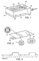
- Figure 1 shows a mobile phone 100 which is of generally conventional form, except as described further herein.
- the phone 100 has a casing 101, which contains a display, for example a liquid crystal display, 102 and a keypad 103.
- the invention is applicable to any device, and in particular to any portable radiocommunications device.
- the phone 100 is provided with one or more temperature sensors, for example a temperature sensor 108 for detecting a temperature of the casing 101, where it is typically held by a user, or a temperature sensor 109 for detecting a temperature of of the display 102, or a temperature sensor 110 for detecting a temperature of of the keypad 103, since the display and keypad are typically adjacent to the user's face in use of the device.
- a temperature sensor 107 could also be provided which detects the temperature of the battery 104.
- the device may include at least one sensor which detects a temperature of a part of the device which has a direct effect on the comfort of the user, for example because it is contacted by the user.
- FIG 2 is a schematic representation of a part of the electronic circuitry within the phone 100.
- the circuitry includes a processor 111, as well as other integrated circuits, filter 112, and power amplifier 113, and a connection to the battery 104.
- the phone 100 may be provided with one or more temperature sensors which detect the temperature of any of these components.
- the temperature sensor which is used may have a dual function.
- the display 109 may include a temperature sensor which is also used to control the contrast thereof.
- the device may include a temperature sensor which is used to detect the temperature of a crystal oscillator within the electronic circuitry, in order to compensate for variations in the performance thereof.
- Figure 3 illustrates a TDMA structure in which the device is operated.
- the device may be a GSM phone, or any other terminal operating in a TDMA system, or other system in which data is transmitted in timeslots.
- GSM Global System for Mobile Communications
- each frame is divided into eight timeslots, numbered 0-7.
- the device is active in three slots out of eight, namely slots 5, 6 and 7.
- the device is active in only one slot out of eight, namely slot 6.
- some data relating to a GSM phone, operated with a 3V power supply will be used.
- a device typically dissipates 0.3W when not transmitting.
- the transmitter uses a peak current of 1.5A. With a voltage of 3V, this gives a power of 4.5W.
- a power of approximately 2W is transmitted through the antenna, leaving 2.5W of heat to be dissipated.
- the temperature of the phone can increase uncomfortably for the user.
- the dissipated power can of course be reduced by decreasing the power of transmitted signals.
- it is often essential to transmit signals at relatively high power levels, in order to achieve an acceptable signal-to-noise ratio or carrier-interference ratio, which will inevitably mean that a certain level of power will need to be dissipated.
- a network for example via a base station
- a mobile terminal when a network (for example via a base station) instructs a mobile terminal to operate at a particular increased transmission power, it may at the same time instruct it to operate in a reduced number of time slots for transmission and/or reception.
- the total power dissipated in the device can be controlled, and its temperature maintained within acceptable limits.
- the terminal may operate in an increased number of time slots for transmission and/or reception.
- Figure 5 shows a time history of the temperature of the device, for example as measured by a temperature sensor located on or close to the casing of the device.
- the device is transmitting during, say, three slots out of eight in each frame, and the temperature of the device is increasing (line 114).
- T 1 the device automatically stops transmitting data at this high rate, and reduces its transmission rate such that during time t 12 (line 115) it transmits in, say, two slots out of every eight slots within a frame.
- the device generates heat at a rate which it can dissipate, and the temperature stabilises.
- time t 13 (line 116) it further reduces its transmission rate and transmits in, say, just one slot out of every eight slots within a frame.
- the temperature of the device then falls as the device is generating heat at a rate lower than that which it can dissipate.
- FIG. 6 is a flow chart showing a method of controlling operation of the mobile device.
- the process begins at step 123, in which the device is transmitting in a certain number of slots, n, in each frame.
- n may therefore be a limit determined by the phone itself, based on temperature or some other intrinsic criterion.
- step 124 it is determined whether a first particular criterion is met. If the criterion is met, the process passes to step 125, and the number, n, is reduced by one. Thus, for example, if the device is originally transmitting in three slots in each frame, after step 125 it transmits in two slots in each frame.
- step 124 If, in step 124, the criterion is not met, the process passes to step 126.
- step 126 it is determined whether a second criterion is met. If the criterion is met, the process passes to step 127, and the number, n, is increased by one. Thus, for example, if the device is originally transmitting in three slots in each frame, after step 127 it transmits in four slots in each frame.
- step 126 If, in step 126, the criterion is not met, the process returns to step 123.
- the maximum number of slots, in which the mobile device can transmit is determined by the mobile device on the basis of intrinsic criteria.
- the terminal or mobile device sends a message (for example, in the case of a GSM or other cellular phone, to a base station) in an appropriate protocol, requesting that the number of allocated slots be reduced.
- the number of slots, in which the device transmits can be adjusted based on the remaining battery capacity. For example, it may be preferable for the user to make a longer call, transmitting data at a relatively low rate, than to transmit data at a relatively high rate, if that causes the battery to fail after a short time. Means may be provided to allow the user to input his wishes, for example the length of call he wishes to make. If the remaining battery capacity is sufficient to allow the desired length of call only if the number of used slots is low, then the number of slots can be controlled appropriately.
- Figure 7 shows a time history of the battery capacity of the device, for example as measured by a conventional method, such as measuring the power supplied by the battery, and the temperature thereof.
- a conventional method such as measuring the power supplied by the battery, and the temperature thereof.
- the device is in standby mode, and the battery capacity remains close to 100%.
- the device is transmitting during, say, three slots out of eight in each frame, and the battery capacity is falling quickly (line 148).
- the temperature reaches a predetermined threshold X
- the device automatically stops transmitting data at this high rate, and reduces its transmission rate such that, during time t 22 (line 149) it transmits in, say, just one slot out of every eight slots within a frame. In this way, the battery life, that is the time until the remaining capacity reaches zero, is extended.
- Figure 8 shows, schematically, (line 154) the slots in which a device has transmitted data over a time period, which is arbitrarily divided into time units (tu).
- line 154 the slots in which a device has transmitted data over a time period, which is arbitrarily divided into time units (tu).
- One possibility is to count the total number of transmission timeslots 155, as indicated in Figure 8 by the running total value 1, 7, 12, 17, etc. The total number of transmission timeslots will give an acceptable estimate of the remaining battery life.
- An alternative is to count the number of transmission timeslots 156 in each time unit, that is, in Figure 8, 6 slots/tu, 5 slots/tu, 5 slots/tu, etc. This will provide an acceptable estimate of the temperature of the device.
- a further alternative is to provide a current meter which detects the current supplied to the device, or to important components thereof such as the transmitter section, receiver section, and/or baseband section.
- the detected current can be integrated over time, and the total will give an estimate of the temperature of the device, since it will be related to the heat dissipated therein.
- the number of slots in which the device can transmit can be controlled on the basis of an estimated battery capacity obtained in these ways.
- the device can not transmit and receive at the same time. For example, this is true in a system with TDMA access method with multislot capability, such as GPRS. In this situation, it may be advantageous to place an upper limit on the number of timeslots in which the device can transmit data, so that more timeslots are available to receive data, or vice versa.
- radio transceiver is used herein to mean any device which can transmit or receive signals.
Abstract
Description
- This invention relates to a radio transceiver, in particular for use in a system in which data can be transmitted at variable rates. More specifically, the invention relates to a method of controlling a rate of data transmission, in order to maintain a desired transceiver operating parameter within a desired range.
- In many existing or proposed digital radiocommunication systems, for example TDMA systems such as GSM/EDGE, CDMA systems such as those defined in IS95, or wideband CDMA (W-CDMA) systems, there exists the possibility for a mobile terminal to transmit data at a variable rate. In general, it is desirable for the terminal to transmit at the highest data rate which is possible, given the available system capacity.
- JP-A-9-326749 discloses a mobile communications device, for use in a TDMA system, in which packet data can be transmitted either continuously, that is in all three time slots of the TDMA system, or intermittently, that is in only one or two of the three TDMA slots.
The device switches between continuous and intermittent mode in dependence on a temperature detected by a temperature sensor located in the vicinity of the power module of the device, which contains the amplifying stage. - However, this requires the use of a separate temperature sensor, which of course increases the number of components in the device.
- Moreover, it is concerned only with the temperature of the electronic components of the device, which may not be the most important factor as far as the user is concerned.
- US 5519886 discloses a method and apparatus for controlling the temperature of a mobile communication device during transmission. The method involves sensing the temperature of a particular portion of the communication device and modifying a data communication protocol in the event that an unacceptable temperature is measured. This leads to the transmission or a portion of it being delayed, or the message being segmented in order to reduce the temperature effects.
- US 5870685 provides a method and apparatus for controlling the operations of a battery-powered mobile station based on the capacity of its battery. The mobile station monitors the capacity of its battery to determine whether it has fallen below any one of a plurality of threshold capacity values. When the capacity of the battery falls below the highest of these threshold values, the mobile station sends a registration cancellation message to the serving system and then disables the transmit operation in order to conserve power.
- EP 0407367 discloses a method and arrangement for dynamically allocating time slots to connections in a digital mobile radio system. The method is concerned with allowing a digital mobile radio system to increase the maximum number of simultaneous connections on a radio channel above the number of time slots available in a frame.
- The present invention relates to a device, and a method of control thereof, in which a rate at which data is transmitted is determined by the remaining capacity of a battery thereof. This can be achieved by directly detecting the remaining battery capacity. Alternatively, the remaining battery capacity can be estimated on the basis of a measure of past usage of the device. For example, the past usage can be determined as a function of the number of timeslots in which the device has transmitted data, or the number of timeslots in which the device has received data, or the sum of these two. Alternatively, the current consumption of the terminal can be used as a measure of the past usage, and hence of the remaining battery capacity.
- If the remaining battery capacity is low, the rate at which data can be transmitted can be reduced.
- Preferably, the rate at which data is transmitted is determined by the number of slots in a TDMA or similar frame structure which are allocated to such transmissions. Thus, the invention applied to all systems with a TDMA access method, including for example, D-AMPS, GSM, PDC, and developments thereof.
- The decision that the rate of data transmission is to be reduced is advantageously taken within the mobile device itself. The device then preferably signals this to a base station or other similar controller.
-
- Figure 1 shows a mobile phone in accordance with an aspect of the invention.
- Figure 2 is a schematic representation of internal components of the phone of Figure 1.
- Figure 3 shows first transmissions from a device in accordance with the invention.
- Figure 4 shows second transmissions from a device in accordance with the invention.
- Figure 5 is a plot of temperature against time for a device.
- Figure 6 is a flow chart illustrating a method in accordance with the invention.
- Figure 7 is a plot of battery capacity against time for a device in accordance with the invention.
- Figure 8 shows third transmissions from a device in accordance with the invention.
-
- Figure 1 shows a
mobile phone 100 which is of generally conventional form, except as described further herein. As is well known, thephone 100 has acasing 101, which contains a display, for example a liquid crystal display, 102 and akeypad 103. The invention is applicable to any device, and in particular to any portable radiocommunications device. - The
phone 100 is provided with one or more temperature sensors, for example atemperature sensor 108 for detecting a temperature of thecasing 101, where it is typically held by a user, or atemperature sensor 109 for detecting a temperature of of thedisplay 102, or atemperature sensor 110 for detecting a temperature of of thekeypad 103, since the display and keypad are typically adjacent to the user's face in use of the device. Atemperature sensor 107 could also be provided which detects the temperature of thebattery 104. Thus, the device may include at least one sensor which detects a temperature of a part of the device which has a direct effect on the comfort of the user, for example because it is contacted by the user. - Figure 2 is a schematic representation of a part of the electronic circuitry within the
phone 100. For illustrative purposes only, the circuitry includes aprocessor 111, as well as other integrated circuits,filter 112, andpower amplifier 113, and a connection to thebattery 104. In addition to, or as an alternative to, the temperature sensors mentioned in connection with Figure 1, thephone 100 may be provided with one or more temperature sensors which detect the temperature of any of these components. - Advantageously, the temperature sensor which is used may have a dual function. For example, the
display 109 may include a temperature sensor which is also used to control the contrast thereof. Alternatively, the device may include a temperature sensor which is used to detect the temperature of a crystal oscillator within the electronic circuitry, in order to compensate for variations in the performance thereof. - Figure 3 illustrates a TDMA structure in which the device is operated. For example, the device may be a GSM phone, or any other terminal operating in a TDMA system, or other system in which data is transmitted in timeslots. In the case of GSM, each frame is divided into eight timeslots, numbered 0-7. In the situation illustrated in Figure 3, the device is active in three slots out of eight, namely
slots - By contrast, in the situation illustrated in Figure 4, the device is active in only one slot out of eight, namely
slot 6. - To illustrate the difference which this will make to the power which must be dissipated by the device, some data relating to a GSM phone, operated with a 3V power supply will be used. Such a device typically dissipates 0.3W when not transmitting. When the device is transmitting at full power, the transmitter uses a peak current of 1.5A. With a voltage of 3V, this gives a power of 4.5W. A power of approximately 2W is transmitted through the antenna, leaving 2.5W of heat to be dissipated.
- When the phone is transmitting for three slots out of eight, the mean power dissipated is therefore:
- By contrast, when the phone is transmitting for one slot out of eight, the mean power dissipated is:
- If a high power is dissipated as heat for long periods, the temperature of the phone can increase uncomfortably for the user.
- The dissipated power can of course be reduced by decreasing the power of transmitted signals. However, it is often essential to transmit signals at relatively high power levels, in order to achieve an acceptable signal-to-noise ratio or carrier-interference ratio, which will inevitably mean that a certain level of power will need to be dissipated.
- Therefore, when a network (for example via a base station) instructs a mobile terminal to operate at a particular increased transmission power, it may at the same time instruct it to operate in a reduced number of time slots for transmission and/or reception. By this means, the total power dissipated in the device can be controlled, and its temperature maintained within acceptable limits.
- Similarly, if it is determined that the terminal should operate at a reduced power, it may operate in an increased number of time slots for transmission and/or reception.
- Figure 5 shows a time history of the temperature of the device, for example as measured by a temperature sensor located on or close to the casing of the device. During time t11, the device is transmitting during, say, three slots out of eight in each frame, and the temperature of the device is increasing (line 114). When the temperature reaches a predetermined threshold T1, the device automatically stops transmitting data at this high rate, and reduces its transmission rate such that during time t12 (line 115) it transmits in, say, two slots out of every eight slots within a frame. During this time, the device generates heat at a rate which it can dissipate, and the temperature stabilises. During time t13 (line 116) it further reduces its transmission rate and transmits in, say, just one slot out of every eight slots within a frame. The temperature of the device then falls as the device is generating heat at a rate lower than that which it can dissipate.
- Figure 6 is a flow chart showing a method of controlling operation of the mobile device. The process begins at
step 123, in which the device is transmitting in a certain number of slots, n, in each frame. In general, it will be desirable for the device to transmit in as many slots as the system permits it to, based on system capacity etc. The number, n, may therefore be a limit determined by the phone itself, based on temperature or some other intrinsic criterion. Instep 124 it is determined whether a first particular criterion is met. If the criterion is met, the process passes to step 125, and the number, n, is reduced by one. Thus, for example, if the device is originally transmitting in three slots in each frame, afterstep 125 it transmits in two slots in each frame. - If, in
step 124, the criterion is not met, the process passes to step 126. Instep 126, it is determined whether a second criterion is met. If the criterion is met, the process passes to step 127, and the number, n, is increased by one. Thus, for example, if the device is originally transmitting in three slots in each frame, afterstep 127 it transmits in four slots in each frame. - If, in
step 126, the criterion is not met, the process returns to step 123. - As described above, the maximum number of slots, in which the mobile device can transmit, is determined by the mobile device on the basis of intrinsic criteria. However, since the slots are in fact allocated to the device by the system, in preferred aspects of the invention the terminal or mobile device sends a message (for example, in the case of a GSM or other cellular phone, to a base station) in an appropriate protocol, requesting that the number of allocated slots be reduced.
- The number of slots, in which the device transmits, can be adjusted based on the remaining battery capacity. For example, it may be preferable for the user to make a longer call, transmitting data at a relatively low rate, than to transmit data at a relatively high rate, if that causes the battery to fail after a short time. Means may be provided to allow the user to input his wishes, for example the length of call he wishes to make. If the remaining battery capacity is sufficient to allow the desired length of call only if the number of used slots is low, then the number of slots can be controlled appropriately.
- Figure 7 shows a time history of the battery capacity of the device, for example as measured by a conventional method, such as measuring the power supplied by the battery, and the temperature thereof. During an initial period, (line 147), the device is in standby mode, and the battery capacity remains close to 100%. Then, during time t21, the device is transmitting during, say, three slots out of eight in each frame, and the battery capacity is falling quickly (line 148). When the temperature reaches a predetermined threshold X, the device automatically stops transmitting data at this high rate, and reduces its transmission rate such that, during time t22 (line 149) it transmits in, say, just one slot out of every eight slots within a frame. In this way, the battery life, that is the time until the remaining capacity reaches zero, is extended.
- As an alternative to a direct measurement of the remaining battery life, it is possible to estimate this factor indirectly.
- Figure 8 shows, schematically, (line 154) the slots in which a device has transmitted data over a time period, which is arbitrarily divided into time units (tu). One possibility is to count the total number of
transmission timeslots 155, as indicated in Figure 8 by the runningtotal value - A further alternative is to provide a current meter which detects the current supplied to the device, or to important components thereof such as the transmitter section, receiver section, and/or baseband section. The detected current can be integrated over time, and the total will give an estimate of the temperature of the device, since it will be related to the heat dissipated therein.
- Thus, the number of slots in which the device can transmit can be controlled on the basis of an estimated battery capacity obtained in these ways.
- Further, in an RF simplex system, the device can not transmit and receive at the same time. For example, this is true in a system with TDMA access method with multislot capability, such as GPRS. In this situation, it may be advantageous to place an upper limit on the number of timeslots in which the device can transmit data, so that more timeslots are available to receive data, or vice versa.
- There are therefore described systems which allow control of the transmissions of a radiocommunications system, based on intrinsic criteria of the device, in order to allow specific performance targets to be met. Although the invention has been described primarily with reference to controlling the rate at which data can be transmitted from a mobile device, any of the same criteria can be used to determine the rate at which data can be received in a mobile device, and the invention is also applicable to other radiocommunication devices. Thus, the term radio transceiver is used herein to mean any device which can transmit or receive signals.
Claims (10)
- A method of operating a radio transceiver (100) operating in a radiocommunication system defining a plurality of time slots (154), the method comprising:the method characterised in that it further comprises:monitoring a battery capacity of the transceiver;controlling a number of slots allocated for transmissions from said transceiver (155) in response to the monitored battery capacity.
- A method of operating a radio transceiver (100) operating in a radiocommunication system defining a plurality of time slots (154), the method comprising:the method characterised in that it further comprises:monitoring a battery capacity of the transceiver;controlling a number of slots allocated for receiving transmissions in said transceiver in response to the monitored battery capacity.
- A method as claimed in claim 1 or 2, wherein the battery capacity is measured directly.
- A method as claimed in claim 1 or 2, wherein the battery capacity is estimated indirectly.
- A method as claimed in claim 4, wherein the battery capacity is estimated on the basis of a measure of past use.
- A method as claimed in claim 4, wherein the battery capacity is estimated on the basis of a measured temperature thereof.
- A method as claimed in claim 5, wherein the measure of past use is the number of time slots in which the transceiver has transmitted data.
- A method as claimed in claim 5, wherein the measure of past use is the past current consumption of at least a part of the transceiver.
- A radiocommunications device comprising a radio transceiver (100) operable in a radiocommunication system defining a plurality of time slots (154), the device comprising:the device characterised in that it further comprises:means for determining a battery capacity of the device;at least one controller for controlling a number of slots allocated for transmissions (155) from said transceiver in response to the determined battery capacity.
- A radiocommunications device comprising a radio transceiver (100) operable in a radiocommunication system defining a plurality of time slots (154), the device comprising:the device characterised in that it further comprises:means for determining a battery capacity of the device;at least one controller for controlling a number of slots allocated for receiving transmissions in said transceiver in response to the determined battery capacity.
Priority Applications (1)
| Application Number | Priority Date | Filing Date | Title |
|---|---|---|---|
| EP03013800A EP1349287B1 (en) | 1999-10-13 | 2000-10-04 | Radio transceiver |
Applications Claiming Priority (3)
| Application Number | Priority Date | Filing Date | Title |
|---|---|---|---|
| GB9924255A GB2355367A (en) | 1999-10-13 | 1999-10-13 | Adjusting allocation of transmission slots according operating conditions in a mobile telephone |
| GB9924255 | 1999-10-13 | ||
| PCT/EP2000/009707 WO2001028105A1 (en) | 1999-10-13 | 2000-10-04 | Radio transceiver |
Related Child Applications (1)
| Application Number | Title | Priority Date | Filing Date |
|---|---|---|---|
| EP03013800A Division EP1349287B1 (en) | 1999-10-13 | 2000-10-04 | Radio transceiver |
Publications (2)
| Publication Number | Publication Date |
|---|---|
| EP1222742A1 EP1222742A1 (en) | 2002-07-17 |
| EP1222742B1 true EP1222742B1 (en) | 2004-04-21 |
Family
ID=10862693
Family Applications (2)
| Application Number | Title | Priority Date | Filing Date |
|---|---|---|---|
| EP00966110A Expired - Lifetime EP1222742B1 (en) | 1999-10-13 | 2000-10-04 | Radio transceiver |
| EP03013800A Expired - Lifetime EP1349287B1 (en) | 1999-10-13 | 2000-10-04 | Radio transceiver |
Family Applications After (1)
| Application Number | Title | Priority Date | Filing Date |
|---|---|---|---|
| EP03013800A Expired - Lifetime EP1349287B1 (en) | 1999-10-13 | 2000-10-04 | Radio transceiver |
Country Status (10)
| Country | Link |
|---|---|
| US (1) | US6934267B1 (en) |
| EP (2) | EP1222742B1 (en) |
| JP (1) | JP2003511950A (en) |
| CN (2) | CN1211935C (en) |
| AT (2) | ATE319228T1 (en) |
| AU (1) | AU7661800A (en) |
| DE (2) | DE60010104D1 (en) |
| GB (1) | GB2355367A (en) |
| MY (1) | MY126721A (en) |
| WO (1) | WO2001028105A1 (en) |
Cited By (1)
| Publication number | Priority date | Publication date | Assignee | Title |
|---|---|---|---|---|
| US8115635B2 (en) | 2005-02-08 | 2012-02-14 | Abbott Diabetes Care Inc. | RF tag on test strips, test strip vials and boxes |
Families Citing this family (39)
| Publication number | Priority date | Publication date | Assignee | Title |
|---|---|---|---|---|
| GB2368499B (en) * | 2000-10-26 | 2004-06-30 | Matsushita Comm Ind Uk Ltd | Mobile communications |
| EP3401794A1 (en) * | 2002-01-08 | 2018-11-14 | Seven Networks, LLC | Connection architecture for a mobile network |
| GB2386507A (en) * | 2002-03-15 | 2003-09-17 | Ubinetics Ltd | Controlling transmission rate |
| DE10241660A1 (en) * | 2002-09-05 | 2004-03-18 | Siemens Ag | Method for temperature control in communications terminal e.g. in mobile RF network systems, has temperature measured within communications terminal for pre-determined time intervals |
| US8169981B2 (en) | 2002-10-31 | 2012-05-01 | Motorola Mobility, Inc. | Method and mobile station for controlling communication via a radio link |
| JP2006514453A (en) | 2003-01-31 | 2006-04-27 | ノキア コーポレイション | Output power control for multi-slot uplink |
| US20040247993A1 (en) * | 2003-05-21 | 2004-12-09 | Sony Ericsson Mobile Communications Ab | System and Method of Improving Talk-Time at the End of Battery Life |
| FR2857100B1 (en) * | 2003-07-02 | 2006-02-10 | Wavecom | METHOD OF ESTIMATING A REMAINING TIME OF USE FOR A RADIO COMMUNICATION DEVICE BATTERY |
| US7689256B2 (en) | 2003-11-10 | 2010-03-30 | Research In Motion Limited | Methods and apparatus for limiting communication capabilities in mobile communication devices |
| US7206567B2 (en) * | 2003-11-10 | 2007-04-17 | Research In Motion Limited | Methods and apparatus for limiting communication capabilities in mobile communication devices |
| JP2005295310A (en) * | 2004-04-01 | 2005-10-20 | Fuji Electric Holdings Co Ltd | Radio communication method, radio communication system, radio terminal, program and recording medium |
| KR100652678B1 (en) * | 2004-10-07 | 2006-12-06 | 엘지전자 주식회사 | Temperature of battery information apparatus and method for mobile station |
| JP4991117B2 (en) * | 2005-03-02 | 2012-08-01 | 日本電気株式会社 | Wireless communication terminal |
| US8774860B2 (en) * | 2005-04-05 | 2014-07-08 | Nokia Corporation | Method and device for low-power FM transmission of audio data to RDS capable FM radio receiver |
| JP4624227B2 (en) * | 2005-09-29 | 2011-02-02 | 京セラ株式会社 | Communication terminal, mobile communication system, and communication control method |
| US7698578B2 (en) | 2006-06-29 | 2010-04-13 | Nokia Corporation | Temperature-dependent power adjustment of transmitter |
| US20080059658A1 (en) * | 2006-06-29 | 2008-03-06 | Nokia Corporation | Controlling the feeding of data from a feed buffer |
| GB0613118D0 (en) * | 2006-06-30 | 2006-08-09 | Nokia Corp | Controlling a mobile device |
| US20080046132A1 (en) * | 2006-08-18 | 2008-02-21 | Nokia Corporation | Control of heat dissipation |
| EP2074826A4 (en) * | 2006-10-11 | 2011-11-09 | Nokia Corp | Service discovery in broadcast networks |
| WO2008062250A1 (en) * | 2006-11-23 | 2008-05-29 | Nokia Corporation | Method and device for maintaining continuity of radio transmissions |
| US7969928B2 (en) | 2007-03-02 | 2011-06-28 | Motorola Solutions, Inc. | Method and apparatus for battery-aware dynamic bandwidth allocation for wireless sensor networks |
| US7933571B2 (en) | 2007-06-20 | 2011-04-26 | Motorola Mobility, Inc. | Method and apparatus for selecting a communication mode based on energy sources in a hybrid power supply |
| US8086229B2 (en) * | 2008-02-25 | 2011-12-27 | Telefonaktiebolaget L M Ericsson (Publ) | Alleviating mobile device overload conditions in a mobile communication system |
| GB2461556A (en) * | 2008-07-03 | 2010-01-06 | Artimi Ltd | Controlling throughput to control temperature in an ultrawideband (UWB) transceiver circuit |
| US8953696B2 (en) | 2008-08-05 | 2015-02-10 | Intel Corporation | Signal decoding systems |
| JP2009207167A (en) * | 2009-05-07 | 2009-09-10 | Nokia Corp | Output power control for multi-slot uplink |
| JP5666572B2 (en) | 2009-06-17 | 2015-02-12 | テレフオンアクチーボラゲット エル エム エリクソン(パブル) | Scheduling data transmission between a mobile terminal and a base station in a wireless communication network |
| JP5244854B2 (en) | 2010-05-14 | 2013-07-24 | 株式会社バッファロー | Wireless communication device |
| WO2013015835A1 (en) | 2011-07-22 | 2013-01-31 | Seven Networks, Inc. | Mobile application traffic optimization |
| EP3647962A1 (en) | 2010-07-26 | 2020-05-06 | Seven Networks, LLC | Context aware traffic management for resource conservation in a wireless network |
| US9667280B2 (en) | 2010-09-24 | 2017-05-30 | Qualcomm Incorporated | Methods and apparatus for touch temperature management based on power dissipation history |
| US20120329410A1 (en) * | 2011-06-24 | 2012-12-27 | Qualcomm Incorporated | Thermal-based flow control |
| US9432169B2 (en) | 2012-08-20 | 2016-08-30 | Adtran, Inc. | Systems and methods for power optimized framing |
| JP5673701B2 (en) * | 2013-02-12 | 2015-02-18 | 富士通株式会社 | Base station, communication terminal, base station communication method, communication terminal communication method, communication system |
| WO2014197521A1 (en) | 2013-06-03 | 2014-12-11 | Seven Networks, Inc. | Blocking/unblocking algorithms for signaling optimization in a wireless network for traffic utilizing proprietary and non-proprietary protocols |
| EP3136796B9 (en) * | 2015-08-27 | 2019-10-30 | Kabushiki Kaisha Toshiba | Transmission power control with variable transmission duration |
| CN105763796B (en) * | 2016-02-29 | 2019-03-01 | Oppo广东移动通信有限公司 | Control method, control device and electronic device |
| US11507156B2 (en) * | 2020-01-30 | 2022-11-22 | Dell Products L.P. | Cooling system with hyperbaric fan and evacuative fan |
Family Cites Families (32)
| Publication number | Priority date | Publication date | Assignee | Title |
|---|---|---|---|---|
| US5619117A (en) * | 1982-06-07 | 1997-04-08 | Norand Corporation | Battery pack having memory |
| JPH0758922B2 (en) * | 1986-08-25 | 1995-06-21 | 株式会社日立製作所 | Temperature rise warning device |
| US5416495A (en) * | 1988-07-07 | 1995-05-16 | Sentex Systems, Inc. | Liquid-crystal display unit for electronic directory |
| US5164652A (en) * | 1989-04-21 | 1992-11-17 | Motorola, Inc. | Method and apparatus for determining battery type and modifying operating characteristics |
| US4949395A (en) * | 1989-07-07 | 1990-08-14 | Telefonaktiebolaget L M Ericsson | Method and arrangement for dynamically allocating time slots to connections in a digital mobile radio system |
| USRE36973E (en) * | 1989-10-12 | 2000-11-28 | Seiko Epson Corporation | Digitally-corrected temperature-compensated crystal oscillator having a correction-suspend control for communications service |
| JP3058923B2 (en) * | 1991-01-11 | 2000-07-04 | 株式会社東芝 | Wireless telephone equipment adapter |
| JPH0537442A (en) * | 1991-07-26 | 1993-02-12 | Oki Electric Ind Co Ltd | Portable telephone set |
| US5248929A (en) * | 1992-04-30 | 1993-09-28 | Murata Machinery, Ltd. | Battery time monitor for cellular telephone |
| US5524275A (en) | 1993-12-17 | 1996-06-04 | Ericsson Ge Mobile Communications Inc. | Averaged RF exposure control |
| JP2606595B2 (en) * | 1994-08-29 | 1997-05-07 | 日本電気株式会社 | Digital wireless communication system |
| US5519886A (en) * | 1994-09-26 | 1996-05-21 | Motorola, Inc. | Method and apparatus for controlling device temperature during transmissions |
| GB2324686B (en) * | 1994-09-30 | 1999-02-10 | Motorola Inc | Method for dynamically allocating wireless communication resources |
| JP3050365B2 (en) * | 1995-03-03 | 2000-06-12 | 日本電気株式会社 | Temperature control method for communication equipment |
| DE19536530C1 (en) * | 1995-09-29 | 1996-11-28 | Siemens Ag | Cordless telecommunication system with secure inter-operability of cordless telecommunication applications |
| US5806007A (en) * | 1995-10-18 | 1998-09-08 | Telefonaktiebolaget Lm Ericsson | Activity control for a mobile station in a wireless communication system |
| EP0800282B1 (en) * | 1996-04-02 | 2005-06-29 | Nec Corporation | Wireless communication equipment for remote station |
| GB2311910B (en) * | 1996-04-03 | 2000-07-12 | Motorola Ltd | Communication system |
| JP2872112B2 (en) * | 1996-06-07 | 1999-03-17 | 埼玉日本電気株式会社 | Mobile communication device control equipment for packet communication |
| US5870685A (en) * | 1996-09-04 | 1999-02-09 | Ericsson Inc. | Mobile station operations management based on battery capacity |
| JP2872156B2 (en) * | 1996-11-13 | 1999-03-17 | 日本電気テレコムシステム株式会社 | Communication mobile terminal |
| FI106759B (en) * | 1996-11-13 | 2001-03-30 | Nokia Mobile Phones Ltd | Mobile transmit power limiting system |
| JP3528477B2 (en) * | 1996-11-18 | 2004-05-17 | シャープ株式会社 | Wireless transceiver |
| FI104135B1 (en) * | 1997-06-24 | 1999-11-15 | Nokia Mobile Phones Ltd | Time division multiple access radio systems |
| KR100234132B1 (en) * | 1997-07-26 | 1999-12-15 | 윤종용 | Method for extending using time of battery in mobile communication terminal |
| JP3374712B2 (en) * | 1997-08-08 | 2003-02-10 | 三菱電機株式会社 | Wireless communication terminal |
| JP2991167B2 (en) * | 1997-08-27 | 1999-12-20 | 三菱電機株式会社 | TDMA variable slot allocation method |
| US6044069A (en) * | 1997-10-29 | 2000-03-28 | Conexant Systems, Inc. | Power management system for a mobile station |
| US6169884B1 (en) * | 1998-04-06 | 2001-01-02 | Sierra Wireless, Inc. | Method and apparatus for reducing power in radio transmitters |
| GB2339113B (en) * | 1998-06-30 | 2003-05-21 | Nokia Mobile Phones Ltd | Data transmission in tdma system |
| US6760311B1 (en) * | 1998-11-20 | 2004-07-06 | Ericsson Inc. | Thermal transmission control of wireless data modem |
| US6433512B1 (en) * | 1999-01-27 | 2002-08-13 | Telefonaktebolaget L M Ericsson (Publ) | Power consumption reporting by an accessory of an electronic device |
-
1999
- 1999-10-13 GB GB9924255A patent/GB2355367A/en not_active Withdrawn
-
2000
- 2000-10-04 WO PCT/EP2000/009707 patent/WO2001028105A1/en active IP Right Grant
- 2000-10-04 AT AT03013800T patent/ATE319228T1/en not_active IP Right Cessation
- 2000-10-04 JP JP2001530211A patent/JP2003511950A/en active Pending
- 2000-10-04 CN CNB008170630A patent/CN1211935C/en not_active Expired - Fee Related
- 2000-10-04 DE DE60010104T patent/DE60010104D1/en not_active Expired - Lifetime
- 2000-10-04 AU AU76618/00A patent/AU7661800A/en not_active Abandoned
- 2000-10-04 AT AT00966110T patent/ATE265107T1/en not_active IP Right Cessation
- 2000-10-04 EP EP00966110A patent/EP1222742B1/en not_active Expired - Lifetime
- 2000-10-04 EP EP03013800A patent/EP1349287B1/en not_active Expired - Lifetime
- 2000-10-04 DE DE60026381T patent/DE60026381D1/en not_active Expired - Lifetime
- 2000-10-04 CN CNB2005100067163A patent/CN100358245C/en not_active Expired - Fee Related
- 2000-10-12 MY MYPI20004769A patent/MY126721A/en unknown
- 2000-10-12 US US09/686,621 patent/US6934267B1/en not_active Expired - Lifetime
Cited By (5)
| Publication number | Priority date | Publication date | Assignee | Title |
|---|---|---|---|---|
| US8115635B2 (en) | 2005-02-08 | 2012-02-14 | Abbott Diabetes Care Inc. | RF tag on test strips, test strip vials and boxes |
| US8223021B2 (en) | 2005-02-08 | 2012-07-17 | Abbott Diabetes Care Inc. | RF tag on test strips, test strip vials and boxes |
| US8358210B2 (en) | 2005-02-08 | 2013-01-22 | Abbott Diabetes Care Inc. | RF tag on test strips, test strip vials and boxes |
| US8390455B2 (en) | 2005-02-08 | 2013-03-05 | Abbott Diabetes Care Inc. | RF tag on test strips, test strip vials and boxes |
| US8542122B2 (en) | 2005-02-08 | 2013-09-24 | Abbott Diabetes Care Inc. | Glucose measurement device and methods using RFID |
Also Published As
| Publication number | Publication date |
|---|---|
| ATE265107T1 (en) | 2004-05-15 |
| CN1409900A (en) | 2003-04-09 |
| EP1349287A1 (en) | 2003-10-01 |
| AU7661800A (en) | 2001-04-23 |
| JP2003511950A (en) | 2003-03-25 |
| GB9924255D0 (en) | 1999-12-15 |
| DE60010104D1 (en) | 2004-05-27 |
| WO2001028105A1 (en) | 2001-04-19 |
| US6934267B1 (en) | 2005-08-23 |
| DE60026381D1 (en) | 2006-04-27 |
| CN100358245C (en) | 2007-12-26 |
| ATE319228T1 (en) | 2006-03-15 |
| CN1642024A (en) | 2005-07-20 |
| CN1211935C (en) | 2005-07-20 |
| EP1222742A1 (en) | 2002-07-17 |
| MY126721A (en) | 2006-10-31 |
| EP1349287B1 (en) | 2006-03-01 |
| GB2355367A (en) | 2001-04-18 |
Similar Documents
| Publication | Publication Date | Title |
|---|---|---|
| EP1222742B1 (en) | Radio transceiver | |
| US7016686B2 (en) | Congestion control in a CDMA-based mobile radio communications system | |
| KR100357014B1 (en) | Mobile terminal, mobile communication system, and power consumption suppressing method for mobile terminal | |
| US5815821A (en) | Method and a device for conserving power in a battery powered transceiver | |
| EP1602220B1 (en) | System and method for battery conservation with assistance from the network and radio resource management | |
| RU2251799C2 (en) | Wireless communication systems | |
| KR100514569B1 (en) | Methods and apparatus for generating timing signals in a radiocommunication unit | |
| KR100713007B1 (en) | Wireless communication terminal and method for adjusting cell signal power measurement period using it | |
| US6192249B1 (en) | Method and apparatus for reverse link loading estimation | |
| JP4800533B2 (en) | Method and apparatus for reverse link load estimation | |
| US6313832B1 (en) | Remaining battery capacity display device | |
| US20100248646A1 (en) | Wireless communication terminal and communication system selection method | |
| US20020072340A1 (en) | Control of receiver immunity to interference by controlling linearity | |
| US6876635B2 (en) | Current reduction by receiver linearity adjustment in a communication device | |
| KR20040084921A (en) | Power saving management for portable devices | |
| EP1455548A2 (en) | Method for determining threshold value for on/off controlling output power of mobile communication terminal | |
| US7194282B2 (en) | Method for controlling transmitting power in a wireless communication device | |
| US20040047327A1 (en) | Quality indicator bit (QIB) generation in wireless communications systems | |
| KR100418837B1 (en) | Transmission power control system and method capable of saving battery consumption of mobile station and preventing connection capacity from being reduced | |
| EP1342327B1 (en) | Congestion control in a cdma-based mobile radio communications system | |
| US6597929B1 (en) | Method for reducing power consumption of a radio terminal by sensing duration of nonservice and/or varying receive period | |
| GB2386507A (en) | Controlling transmission rate | |
| JP2002142014A (en) | Communication unit | |
| JPH09331290A (en) | Portable telephone set | |
| GB2387291A (en) | Maintaining system clock accuracy of a mobile apparatus whilst maximising battery life of the apparatus |
Legal Events
| Date | Code | Title | Description |
|---|---|---|---|
| PUAI | Public reference made under article 153(3) epc to a published international application that has entered the european phase |
Free format text: ORIGINAL CODE: 0009012 |
|
| 17P | Request for examination filed |
Effective date: 20020507 |
|
| AK | Designated contracting states |
Kind code of ref document: A1 Designated state(s): AT BE CH CY DE DK ES FI FR GB GR IE IT LI LU MC NL PT SE |
|
| AX | Request for extension of the european patent |
Free format text: AL;LT;LV;MK;RO;SI |
|
| 17Q | First examination report despatched |
Effective date: 20021213 |
|
| GRAP | Despatch of communication of intention to grant a patent |
Free format text: ORIGINAL CODE: EPIDOSNIGR1 |
|
| GRAS | Grant fee paid |
Free format text: ORIGINAL CODE: EPIDOSNIGR3 |
|
| GRAA | (expected) grant |
Free format text: ORIGINAL CODE: 0009210 |
|
| AK | Designated contracting states |
Kind code of ref document: B1 Designated state(s): AT BE CH CY DE DK ES FI FR GB GR IE IT LI LU MC NL PT SE |
|
| PG25 | Lapsed in a contracting state [announced via postgrant information from national office to epo] |
Ref country code: IT Free format text: LAPSE BECAUSE OF FAILURE TO SUBMIT A TRANSLATION OF THE DESCRIPTION OR TO PAY THE FEE WITHIN THE PRE;WARNING: LAPSES OF ITALIAN PATENTS WITH EFFECTIVE DATE BEFORE 2007 MAY HAVE OCCURRED AT ANY TIME BEFORE 2007. THE CORRECT EFFECTIVE DATE MAY BE DIFFERENT FROM THE ONE RECORDED.SCRIBED TIME-LIMIT Effective date: 20040421 Ref country code: AT Free format text: LAPSE BECAUSE OF FAILURE TO SUBMIT A TRANSLATION OF THE DESCRIPTION OR TO PAY THE FEE WITHIN THE PRESCRIBED TIME-LIMIT Effective date: 20040421 Ref country code: LI Free format text: LAPSE BECAUSE OF FAILURE TO SUBMIT A TRANSLATION OF THE DESCRIPTION OR TO PAY THE FEE WITHIN THE PRESCRIBED TIME-LIMIT Effective date: 20040421 Ref country code: NL Free format text: LAPSE BECAUSE OF FAILURE TO SUBMIT A TRANSLATION OF THE DESCRIPTION OR TO PAY THE FEE WITHIN THE PRESCRIBED TIME-LIMIT Effective date: 20040421 Ref country code: FR Free format text: LAPSE BECAUSE OF FAILURE TO SUBMIT A TRANSLATION OF THE DESCRIPTION OR TO PAY THE FEE WITHIN THE PRESCRIBED TIME-LIMIT Effective date: 20040421 Ref country code: BE Free format text: LAPSE BECAUSE OF FAILURE TO SUBMIT A TRANSLATION OF THE DESCRIPTION OR TO PAY THE FEE WITHIN THE PRESCRIBED TIME-LIMIT Effective date: 20040421 Ref country code: CY Free format text: LAPSE BECAUSE OF FAILURE TO SUBMIT A TRANSLATION OF THE DESCRIPTION OR TO PAY THE FEE WITHIN THE PRESCRIBED TIME-LIMIT Effective date: 20040421 Ref country code: CH Free format text: LAPSE BECAUSE OF FAILURE TO SUBMIT A TRANSLATION OF THE DESCRIPTION OR TO PAY THE FEE WITHIN THE PRESCRIBED TIME-LIMIT Effective date: 20040421 Ref country code: FI Free format text: LAPSE BECAUSE OF FAILURE TO SUBMIT A TRANSLATION OF THE DESCRIPTION OR TO PAY THE FEE WITHIN THE PRESCRIBED TIME-LIMIT Effective date: 20040421 |
|
| REG | Reference to a national code |
Ref country code: GB Ref legal event code: FG4D |
|
| REG | Reference to a national code |
Ref country code: CH Ref legal event code: EP |
|
| RAP2 | Party data changed (patent owner data changed or rights of a patent transferred) |
Owner name: TELEFONAKTIEBOLAGET LM ERICSSON (PUBL) |
|
| REG | Reference to a national code |
Ref country code: IE Ref legal event code: FG4D |
|
| REF | Corresponds to: |
Ref document number: 60010104 Country of ref document: DE Date of ref document: 20040527 Kind code of ref document: P |
|
| NLT2 | Nl: modifications (of names), taken from the european patent patent bulletin |
Owner name: TELEFONAKTIEBOLAGET LM ERICSSON (PUBL) |
|
| PG25 | Lapsed in a contracting state [announced via postgrant information from national office to epo] |
Ref country code: DK Free format text: LAPSE BECAUSE OF FAILURE TO SUBMIT A TRANSLATION OF THE DESCRIPTION OR TO PAY THE FEE WITHIN THE PRESCRIBED TIME-LIMIT Effective date: 20040721 Ref country code: SE Free format text: LAPSE BECAUSE OF FAILURE TO SUBMIT A TRANSLATION OF THE DESCRIPTION OR TO PAY THE FEE WITHIN THE PRESCRIBED TIME-LIMIT Effective date: 20040721 Ref country code: GR Free format text: LAPSE BECAUSE OF FAILURE TO SUBMIT A TRANSLATION OF THE DESCRIPTION OR TO PAY THE FEE WITHIN THE PRESCRIBED TIME-LIMIT Effective date: 20040721 |
|
| PG25 | Lapsed in a contracting state [announced via postgrant information from national office to epo] |
Ref country code: DE Free format text: LAPSE BECAUSE OF FAILURE TO SUBMIT A TRANSLATION OF THE DESCRIPTION OR TO PAY THE FEE WITHIN THE PRESCRIBED TIME-LIMIT Effective date: 20040722 |
|
| PG25 | Lapsed in a contracting state [announced via postgrant information from national office to epo] |
Ref country code: ES Free format text: LAPSE BECAUSE OF FAILURE TO SUBMIT A TRANSLATION OF THE DESCRIPTION OR TO PAY THE FEE WITHIN THE PRESCRIBED TIME-LIMIT Effective date: 20040801 |
|
| LTIE | Lt: invalidation of european patent or patent extension |
Effective date: 20040421 |
|
| NLV1 | Nl: lapsed or annulled due to failure to fulfill the requirements of art. 29p and 29m of the patents act | ||
| PG25 | Lapsed in a contracting state [announced via postgrant information from national office to epo] |
Ref country code: LU Free format text: LAPSE BECAUSE OF NON-PAYMENT OF DUE FEES Effective date: 20041004 Ref country code: IE Free format text: LAPSE BECAUSE OF NON-PAYMENT OF DUE FEES Effective date: 20041004 |
|
| REG | Reference to a national code |
Ref country code: CH Ref legal event code: PL |
|
| PG25 | Lapsed in a contracting state [announced via postgrant information from national office to epo] |
Ref country code: MC Free format text: LAPSE BECAUSE OF NON-PAYMENT OF DUE FEES Effective date: 20041031 |
|
| PLBE | No opposition filed within time limit |
Free format text: ORIGINAL CODE: 0009261 |
|
| STAA | Information on the status of an ep patent application or granted ep patent |
Free format text: STATUS: NO OPPOSITION FILED WITHIN TIME LIMIT |
|
| EN | Fr: translation not filed | ||
| 26N | No opposition filed |
Effective date: 20050124 |
|
| REG | Reference to a national code |
Ref country code: IE Ref legal event code: MM4A |
|
| PG25 | Lapsed in a contracting state [announced via postgrant information from national office to epo] |
Ref country code: PT Free format text: LAPSE BECAUSE OF NON-PAYMENT OF DUE FEES Effective date: 20040921 |
|
| PGFP | Annual fee paid to national office [announced via postgrant information from national office to epo] |
Ref country code: GB Payment date: 20081029 Year of fee payment: 9 |
|
| PG25 | Lapsed in a contracting state [announced via postgrant information from national office to epo] |
Ref country code: GB Free format text: LAPSE BECAUSE OF NON-PAYMENT OF DUE FEES Effective date: 20091004 |