EP1229391A2 - Process and device for handling a surface to be exposed, particularly a printing plate - Google Patents
Process and device for handling a surface to be exposed, particularly a printing plate Download PDFInfo
- Publication number
- EP1229391A2 EP1229391A2 EP01126074A EP01126074A EP1229391A2 EP 1229391 A2 EP1229391 A2 EP 1229391A2 EP 01126074 A EP01126074 A EP 01126074A EP 01126074 A EP01126074 A EP 01126074A EP 1229391 A2 EP1229391 A2 EP 1229391A2
- Authority
- EP
- European Patent Office
- Prior art keywords
- exposure
- area
- printing plate
- exposure surface
- feed
- Prior art date
- Legal status (The legal status is an assumption and is not a legal conclusion. Google has not performed a legal analysis and makes no representation as to the accuracy of the status listed.)
- Granted
Links
Images
Classifications
-
- G—PHYSICS
- G03—PHOTOGRAPHY; CINEMATOGRAPHY; ANALOGOUS TECHNIQUES USING WAVES OTHER THAN OPTICAL WAVES; ELECTROGRAPHY; HOLOGRAPHY
- G03F—PHOTOMECHANICAL PRODUCTION OF TEXTURED OR PATTERNED SURFACES, e.g. FOR PRINTING, FOR PROCESSING OF SEMICONDUCTOR DEVICES; MATERIALS THEREFOR; ORIGINALS THEREFOR; APPARATUS SPECIALLY ADAPTED THEREFOR
- G03F7/00—Photomechanical, e.g. photolithographic, production of textured or patterned surfaces, e.g. printing surfaces; Materials therefor, e.g. comprising photoresists; Apparatus specially adapted therefor
- G03F7/20—Exposure; Apparatus therefor
- G03F7/24—Curved surfaces
Definitions
- the invention relates to a method for handling an exposure surface to be exposed, especially a printing plate, when it is brought into the exposure area an exposure unit and / or when discharging from an exposure unit, preferably a platesetter, in particular an inner drum platesetter.
- the invention further relates to a device for handling a device to be exposed Exposure area, in particular a printing plate, when introduced into the exposure area of an exposure unit and / or during application an exposure unit, preferably a platesetter, in particular an inner drum printing platesetter, preferably for performing the aforementioned method.
- a device for handling a device to be exposed Exposure area in particular a printing plate, when introduced into the exposure area of an exposure unit and / or during application an exposure unit, preferably a platesetter, in particular an inner drum printing platesetter, preferably for performing the aforementioned method.
- the exposure area to be exposed can in particular be a film for exposure be a printing plate or a printing plate itself to be directly exposed, wherein it it again does not matter whether it is a metallic pressure plate or a Printing plate made of plastic, for example polyester.
- the type of exposure in principle also does not matter. So it can be, for example Exposure to visible light, exposure to ultraviolet light or else thermal exposure with high-energy light in the ablation process act.
- the exposure area to be exposed must be in the exposure area the exposure unit of an exposure device, e.g. B. a film or Platesetter, are introduced and after the exposure process are brought out of the exposure unit again.
- an exposure device e.g. B. a film or Platesetter
- imagesetters with respect to their geometry in the exposure unit from each other distinguished, namely inner drum imagesetter with a trough-shaped Exposure area into which the exposure area must be introduced, external drum imagesetter, the exposure surface spanned on the outside of the drum and flatbed imagesetters, in which the exposure surface is not curved, flat is introduced.
- the exposure area to be exposed is usually used inserted from a feed area and after exposure into one Execution area, taking care of this guidance and transportation Transport and deflection rollers, conveyor belts, belts, rollers, guide plates or the same elements and organs can be used.
- the exposure areas themselves are mechanically very stressed. In particular, it can also damage the exposed area Front side in the field to be exposed on the exposure area to be exposed come, whereby the result desired by the exposure to uselessness can be affected.
- the invention is therefore based on the object of a method or a device of the type mentioned at the outset to show that the exposure area is handled more gently, but preferably also a more reliably reproducible and automatable and ultimately more precise Handling sequence is realized.
- This object is achieved in terms of the method in that the exposure area hangs temporarily.
- a hanging exposure area only has to be held in an upper edge area the outside of the field to be exposed on the front of the exposure area may lie while in other areas of the exposure area Contacts can be avoided.
- the exposure surface for example on the back, advantageously in one hanging position and in the area of the exposure unit put down, for example, into a hollow of an inner drum, where it in turn gets direct contact with the exposure unit with its back, without any other guiding elements or transport elements in between need to contact the exposure area.
- the one to be exposed This advantageously means that the field area remains completely protected.
- the exposure area to be exposed can thus preferably consist of approximately horizontal orientation in a feed area or loading area, e.g. from a kind of table top or from a magazine, in a hanging orientation are transferred and lowered for introduction into the exposure unit. After exposure, it can in particular preferably be on the same or on a another way back or to another discharge area become.
- the exposure area is as already briefly mentioned, preferably only detected and pulled up in an edge region. This can be reduced in friction and also gentle on the back of the exposure surface on an air cushion that can be generated with supplied air.
- the exposure area then before lowering into the exposure unit has reached its hanging position, conversely, an air extraction under or behind the back of the exposure area to ensure some adhesion to reach the exposure area on a guide, so that the exposure area can still be easily moved, but is guided by a system and can be moved more precisely, especially without bulging out, swerving or tilted.
- the exposure area during the Exposure preferably through (stronger) air intake in the exposure unit fixed non-slip.
- the exposure area in the feed or discharge area and / or aligned in the exposure area for example by simple Baffles.
- a further development of the method according to the invention provides that the Stamped exposure area after the exposure process in the fixed state becomes.
- the device according to the invention preferably comprises a lifting and lowering device for the exposure area to be exposed.
- the suspension device has at least one gripper for gripping at the edge or clasping the exposure surface. So that the exposure area with the greatest possible protection, in particular of the exposure-effective area, be detected and raised.
- the suspension device For guiding the lifting and lowering device and the exposure area to be exposed itself, the suspension device preferably has an approximately perpendicular extension Loading boom, which is particularly space-saving.
- a next development of the invention advantageously provides that the suspension device even directly to a feed area for those to be exposed Exposure areas can be accessed.
- the feed area can be Example include an approximately horizontal table top, but it can for example also a preferably interchangeable and dockable magazine include, with a larger number of exposure areas in the feed area can be introduced. Magazine handling is special then displayed when working with exposure areas that are sensitive to daylight are inserted into the imagesetter in such a way that they are protected from light and possibly can be applied again in the same way. In particular is the reloading of the imagesetter by the invention as a whole automatable and the utilization of the imagesetter more economical.
- the entry or entry area to the exposure unit is advantageous for the workflow arranged below the hanging device so that the exposure area hanging lowered and directed to the exposure position can be.
- a preferably provided way switch ensures that the exposure surface either from the hanging position in the exposure device or in the Exhaust area arrives, which can coincide with the feed area.
- An alignment device preferably ensures the alignment of the exposure surface, preferably in each respective area. So it can Alignment device in the infeed and outfeed areas to align the exposure surface there in the transverse direction, and it For example, sliding blocks can be guided in grooves in the exposure area to shift and align the exposure area in the direction of its path or to position.
- the device at least an air blower and / or suction device for specifying sliding and / or Adhering the exposure surface in at least one area of the device, with, for example, depending on the air flow strength and direction, when pulling up the exposure surface can slide on an air cushion when lowering can be easily adhered by light air intake and after the Positioning in the exposure device fixed by stronger air intake can be.
- a punch for punching the exposure area at the exit is preferred the exposure unit as part of the device according to the invention provided with which the exposure surface after exposure with punched recesses can be provided. This is used for positioning or clamping the exposure area in a subsequent device.
- the device according to the invention is particularly advantageous as a component or in direct connection with a platesetter because it is relatively stiff and nevertheless sufficiently flexible printing plates made of any suitable material is particularly good, precise, economical and continuous with a high throughput and handle degree of automation with the device according to the invention to let.
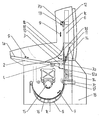
- the figure shows a device according to the invention in a schematic cross section along the path of an exposure area to be exposed through the device, an edge view of an exposure area in various examples selected positions in the drawing is indicated and so the Movement sequence in the device clarified.
- the device according to the invention enables this in a particularly good manner Handling of preferably offset printing plates before, during and after a Exposure.
- the printing plates or, more generally, the plates to be exposed can be used Exposure areas of various formats, thicknesses or coatings have and yet gentle, fast and register accurate in one Inner drum, on an outer drum or on a flat exposure table an exposure unit.
- the invention can Device also have a compact design, a small one Create "footprint", be inexpensive and work, especially through a relatively simple mechanics with relatively few components and simple and clear Movements. At the same time, high functional reliability is guaranteed.
- the device has no complicated and bulky structures on the exposure unit and can be loaded or reloaded manually as well as fully automatically.
- the exposure area is not touched in its printing area, but only held in the area or environment of a possible punching.
- the imagesetter shown has a feed area for printing plates to be exposed 1a on a platter table 2 which, for ergonomic reasons, is about 10 ° is arranged inclined into the imagesetter. This inclination slips an inserted pressure plate 1 a also advantageous due to its gravity automatically into a desired feed position up to a stop 3.
- a fan 4 is an air cushion or on the table surface of the table top 2 Air cushion generated below the pressure plate 1 a, so that they are in this feed area slides with reduced friction.
- the centering of the printing plate 1a on the plate table 2 is done by means of two counter-rotating centering slides 5. This sliding device goes automatically return to their zero position. This zero setting is made by a Sensor queried. The presence of a printing plate 1a on the table is also determined by a plate presence sensor.
- the assembly with the table top 2 is self-supporting and can, if desired to be removed completely, for example if the imagesetter becomes one Fully automatic machines with automatic plate reloading upgraded from a magazine shall be.
- the device according to the invention comprises an upstanding loading boom 6 which a gripping device for gripping the pressure plate 1 a is suspended, which in the drawing in a lower position with 7a and in an upper position with 7b is designated. According to these positions, the gripping device 7a, 7b the pressure plate 1a via an intermediate position 1b to a hanging position 1c pulled up.
- Different positions of the pressure plate in the device are for Illustration of their movement sequence shown in the drawing and each with the reference number 1 with the addition of different lower case letters designated with 1a to 1e.
- the loading boom 6 with its gripping device 7 has the task of the pressure plate 1 from the turntable 2 via the hanging position 1c into an exposure unit 8 and to be transported back to the turntable 2 in the same way illustrated embodiment of a device according to the invention also as Removal or discharge area for the fully exposed printing plate 1 is used.
- the path of the pressure plate 1 through the device is in accordance with its two Passage directions marked with double arrows 9. Supported and controlled is the course of movement by a trained as a path, in the direction the double arrow 10 pivotable pressure plate guide 11, 11 '.
- the loading boom 6 is designed so that it remains unchanged even in a fully automatic Device can be used. It is supported in the area of the printing plate guide 11 onwards.
- the gripping device 7 is designed as a gripper bar, which is on a carriage a recirculating ball guide that runs through a stepper motor with gearbox Toothed belt is driven.
- the gripper bar has a swivel joint 12 in order that the gripper bar can be pivoted in the directions of a double arrow 12a can, in order to feed the printing plate 1 vertically to the exposure unit 8 and on the other hand the printing plate 1 almost horizontally from the platen table 2 to pick up or put back there. Swiveling up and opening the Gripper bar is accomplished with a motor and queried with sensors. A spring 13 presses the gripper bar without current.
- the gripper bar has alignment stops for the printing plate 1. In addition, the presence is checked by a sensor checked the pressure plate 1 in the gripper bar.
- the plate guide 11 has the task of securely inserting the printing plate 1 into the exposure unit 8 lead, and it must the illustrated printing plate 1 for storage steer the turntable 2.
- the area of the plate guide 11 carries the loading boom 6 and is attached to the exposure unit 8.
- the honeycomb plate forms the frame of the plate guide 11. Since the pressure plate 1 is gripped only at the upper end by the gripper bar, create vacuum Fan 14 in the honeycomb plate for the pressure plate on the loading boom 6 is inserted along and against the exposure unit 8.
- the fans 14 are designed so that the pressure plate 1 cannot bulge or bend away, pushing the pressure plate is still possible and is guaranteed.
- On the plate guide 11 is for placing the printing plate 1 on the plate table 2 an unloading device attached.
- the exposure unit 8 is an inner drum printing plate exposer shown as an example.
- the printing plate 1e is positioned, fixed and illustrated in the exposure unit 8.
- the exposure unit 8 essentially consists of an exposure head 15 with optical exposure means, a trough 16 or inner drum shell as a bed for the printing plate 1e to be exposed in the exposure unit, in its axis line the exposure head 15 is arranged, a disc slide not recognizable for positioning the pressure plate 1e in the trough 16, the slide finger tower in the trough 15, and a pull punch 17 for punching the Pressure plate 1e after exposure when pressure plate 1e emerges from the trough 16th
- the trough 16 has a special sliding coating, via which the pressure plate 1e Your back can slide. Vacuum grooves on parallel circumferential lines of the Trough 16 run on the inside, are arranged so that one possible large number of different plate formats can be sucked in.
- the vacuum or the suction of air by means of a pump device, not shown 18 is used to fix the printing plate 1e during exposure and Punching.
- the punch 17 is fixed to the tray 16 on the plate inlet side of the tray 16 connected and adjusted to the trough 16.
- the sliding fingers or sliding blocks of the The plate slide and for the plate slide drive timing belt has the recess two guide grooves not shown in the circumferential direction.
- the sliding fingers are driven by motors via toothed belts and against the edge of the Pressure plate 1e pressed. They have the task on the one hand, the pressure plate 1e Suction against the surface of the well and on the other hand for support the gripping device 7 hanging on the loading boom 6 has the pressure plate 1e to press against the extended punch of punch 17.
- the stamps can for exposure as positioning stops for the printing plate 1e serve, and the pressure plate can then still be sucked in the same Position to be punched immediately after exposure. Alternatively, you can also suitable stops of the gripping device 7 for positioning the pressure plate 1e serve.
- the handling of the printing plate 1 in the illustrated embodiment The inner drum printing platesetter essentially works as follows:
- the device is switched on. For initializing the device or for Various functions of the device can be checked for operational readiness tried and tested and checked by sensors. Is this Device ready for operation, this can be indicated with a lamp, for example.
- an automatic reload could also be used a new pressure plate can be pulled out of a magazine.
- a sensor in the turntable 2 detects the presence of a new printing plate and a plate sensor in the gripper switches the fan 4 on, so that the pressure plate on a Air cushion hovers.
- the centering slide 5 can then monitor the pressure plate by sensors center and also determine the plate width, after which the centering slide release the pressure plate again.
- the further process can be automated or the operator presses it a start button 19 for the further process.
- the gripping device 7a recognizes and grips the pressure plate 1a.
- the vertical motor with which the gripping device 7a in the position 7b with entrainment and lifting the pressure plate 1a is pulled up to the position 1c, is switched on.
- the upper fan 14 is also switched on.
- the engine with which Gripper joint 12 is pivoted, is started so that it by its own weight in the vertical orientation pivots.
- the fan 4 of the turntable 2 is switched off.
- the vertical motor accelerates to around 400 mm / s.
- the vertical motor runs by counting encoder clocks a certain way depending on the respective Printing plate length until the printing plate in position 1c in full length in vertical orientation depends.
- the upper fan 14 sucks the pressure plate end on.
- a resolution of 0.1 mm is used for positioning accuracy target of ⁇ 1 mm.
- it can be a sensor for detection the pressure plate length or the pressure plate end and a sensor for the detection of the system of the printing plate 1 is provided on the plate guide his.
- the route switch is in position 11 and the lower fan 14 is switched on.
- the pressure plate is then moved to position 1d to with the vertical motor lowered into position 1e in the trough 16 and moved.
- the vertical motor of the gripping device initially pushes the pressure plate about 15 mm beyond their exposure position in the trough, so that behind the pressure plate, also unhindered by the relatively narrow gripping device, the punch the punch 17 can extend. Then the punch is used as a stop taken for the pressure plate and to support the gripping device by the gripping device pushes the pressure plate back up about 15 mm pulls the punch.
- the sliding fingers also slide with the now switched on Engine with. Only then will the printing plate be found in its now Exposure position 1e fixed by in the recess under the pressure plate with the Pump device 18 a vacuum is generated. Then the exposure carried out.
- the punch of the punch 17 is completely retracted and thereby punching the exposed printing plate (pull punch). Moreover becomes the path for the pressure plate to exit the trough 16 free.
- the pump device 18 is switched off so that the vacuum in the trough 16 omitted and the pressure plate is free for movement.
- the bottom and the upper fan 14 switched on for guiding the printing plate. With the Vertical motor and the gripping device 7 driven thereby becomes the plate then pulled back to its upper position 1c. The lower end of the pressure plate 1c is in turn queried by a sensor. The lower fan 14 will then off.
- the corresponding sensors are then used to query whether the turntable 2 is free is and the centering slide 5 have moved apart.
- the route is in brought their position 11 '.
- the vertical motor then lowers the gripping device 7b and the pressure plate 1c attached to it and deflects them accordingly the switch position on the turntable 2 via position 1b to position 1a.
- the swivel is used to turn the joint 12 of the gripping device 7 angled. Before that, the path is out of the way Position 11 'pivoted back to position 11 as soon as the lower edge of the Pressure plate in position 1b reached the platen table 2 and the steering of the Pressure plate on the platen 2 was guaranteed to pave the way for the further Lower the gripper bar to release.
- the pressure plate is not released during the entire process in the imagesetter, but rather is kept controlled, namely during transport, when fixing, during exposure, when punching and transporting.
Abstract
Die Erfindung betrifft ein Verfahren und eine Vorrichtung zur Handhabung einer zu belichtenden Belichtungsfläche, insbesondere einer Druckplatte, beim Einbringen in den Belichtungsbereich einer Belichtungseinheit und/oder beim Ausbringen aus einer Belichtungseinheit, vorzugsweise eines Druckplattenbelichters, insbesondere eines Innentrommel-Druckplattenbelichters. Das erfindungsgemäße Verfahren zeichnet sich dadurch aus, daß die Belichtungsfläche übergangsweise hängt, und zwar vorzugsweise dadurch, daß die Belichtungsfläche aus einer etwa waagerechten Orientierung in einem Zuführungsbereich oder Ladebereich in eine hängende Orientierung überführt wird und zur Einbringung in die Belichtungseinheit abgesenkt wird.The invention relates to a method and a device for handling an exposure surface to be exposed, in particular a printing plate, when it is introduced into the exposure area of an exposure unit and / or when it is discharged from an exposure unit, preferably a printing plate exposer, in particular an inner drum printing plate exposer. The method according to the invention is characterized in that the exposure area hangs transitionally, and preferably in that the exposure area is converted from an approximately horizontal orientation in a feed area or loading area to a hanging orientation and is lowered for introduction into the exposure unit.
Description
Die Erfindung betrifft ein Verfahren zur Handhabung einer zu belichtenden Belichtungsfläche, insbesondere einer Druckplatte, beim Einbringen in den Belichtungsbereich einer Belichtungseinheit und/oder beim Ausbringen aus einer Belichtungseinheit, vorzugsweise eines Druckplattenbelichters, insbesondere eines Innentrommel-Druckplattenbelichters.The invention relates to a method for handling an exposure surface to be exposed, especially a printing plate, when it is brought into the exposure area an exposure unit and / or when discharging from an exposure unit, preferably a platesetter, in particular an inner drum platesetter.
Des weiteren betrifft die Erfindung eine Vorrichtung zur Handhabung einer zu belichtenden Belichtungsfläche, insbesondere einer Druckplatte, beim Einbringen in den Belichtungsbereich einer Belichtungseinheit und/oder beim Ausbringen aus einer Belichtungseinheit, vorzugsweise eines Druckplattenbelichters, insbesondere eines Innentrommel-Druckplattenbelichters, vorzugsweise zur Durchführung des vorgenannten Verfahrens.The invention further relates to a device for handling a device to be exposed Exposure area, in particular a printing plate, when introduced into the exposure area of an exposure unit and / or during application an exposure unit, preferably a platesetter, in particular an inner drum printing platesetter, preferably for performing the aforementioned method.
Die zu belichtende Belichtungsfläche kann insbesondere ein Film zur Belichtung einer Druckplatte sein oder eine direkt zu belichtende Druckplatte selbst, wobei es dabei wiederum egal ist, ob es sich um eine metallische Druckplatte oder um eine Druckplatte aus Kunststoff, bspw. aus Polyester, handelt. Die Art der Belichtung spielt prinzipiell ebenfalls keine Rolle. Es kann sich also beispielsweise um eine Belichtung mit sichtbarem Licht, eine Belichtung mit ultraviolettem Licht oder auch eine thermische Belichtung mit hochenergetischem Licht im Ablationsverfahren handeln.The exposure area to be exposed can in particular be a film for exposure be a printing plate or a printing plate itself to be directly exposed, wherein it it again does not matter whether it is a metallic pressure plate or a Printing plate made of plastic, for example polyester. The type of exposure in principle also does not matter. So it can be, for example Exposure to visible light, exposure to ultraviolet light or else thermal exposure with high-energy light in the ablation process act.
Für die Belichtung muß die zu belichtende Belichtungsfläche in den Belichtungsbereich der Belichtungseinheit einer Belichtungsvorrichtung, also z. B. eines Filmoder Plattenbelichters, eingebracht werden und nach dem Belichtungsvorgang wieder aus der Belichtungseinheit ausgebracht werden. Es werden insbesondere drei Arten von Belichtern bezüglich ihrer Geometrie in der Belichtungseinheit voneinander unterschieden, nämlich Innentrommelbelichter mit einem muldenförmigen Belichtungsbereich, in den die Belichtungsfläche eingeführt werden muß, Außentrommelbelichter, auf deren Trommelaußenseite die Belichtungsfläche aufgespannt wird, und Flachbettbelichter, in die die Belichtungsfläche ungekrümmt, flach eingebracht wird.For the exposure, the exposure area to be exposed must be in the exposure area the exposure unit of an exposure device, e.g. B. a film or Platesetter, are introduced and after the exposure process are brought out of the exposure unit again. It will be particularly three types of imagesetters with respect to their geometry in the exposure unit from each other distinguished, namely inner drum imagesetter with a trough-shaped Exposure area into which the exposure area must be introduced, external drum imagesetter, the exposure surface spanned on the outside of the drum and flatbed imagesetters, in which the exposure surface is not curved, flat is introduced.
Bei allen drei Arten von Belichtern wird die zu belichtende Belichtungsfläche üblicherweise aus einem Zuführungsbereich eingeführt und nach der Belichtung in einen Abführungsbereich ausgeführt, wobei für diese Führung und den Transport Transport- und Umlenkwalzen, Förderbänder, Riemen, Rollen, Leitbleche oder dergleichen Elemente und Organe verwendet werden. Bei einer solchen Handhabung werden die Belichtungsflächen jedoch selbst mechanisch sehr beansprucht. Insbesondere kann es dabei auch zu Beschädigungen auf der zu belichtenden Vorderseite in dem zu belichtenden Feld der zu belichtenden Belichtungsfläche kommen, wodurch das durch die Belichtung gewünschte Ergebnis bis zur Unbrauchbarkeit beeinträchtigt werden kann.With all three types of imagesetters, the exposure area to be exposed is usually used inserted from a feed area and after exposure into one Execution area, taking care of this guidance and transportation Transport and deflection rollers, conveyor belts, belts, rollers, guide plates or the same elements and organs can be used. With such handling However, the exposure areas themselves are mechanically very stressed. In particular, it can also damage the exposed area Front side in the field to be exposed on the exposure area to be exposed come, whereby the result desired by the exposure to uselessness can be affected.
Der Erfindung liegt daher die Aufgabe zugrunde, ein Verfahren bzw. eine Vorrichtung der eingangs genannten Gattung im Hinblick darauf aufzuzeigen, daß die Belichtungsfläche schonender gehandhabt wird, vorzugsweise zudem aber auch ein zuverlässiger reproduzierbarer und automatisierbarer und letztlich auch präziserer Handhabungsablauf verwirklicht wird.The invention is therefore based on the object of a method or a device of the type mentioned at the outset to show that the exposure area is handled more gently, but preferably also a more reliably reproducible and automatable and ultimately more precise Handling sequence is realized.
Diese Aufgabe wird erfindungsgemäß in Verfahrenshinsicht dadurch gelöst, daß die Belichtungsfläche übergangsweise hängt.This object is achieved in terms of the method in that the exposure area hangs temporarily.
Eine hängende Belichtungsfläche muß nur in einem oberen Randbereich gehalten werden, der außerhalb des zu belichtenden Feldes der Vorderseite der Belichtungsfläche liegen kann, während in übrigen Bereichen der Belichtungsfläche Kontakte vermieden werden können. Insbesondere kann also erfindungsgemäß die beispielsweise auf ihrer Rückseite liegende Belichtungsfläche mit Vorteil in eine hängende Position aufgenommen werden und in den Bereich der Belichtungseinheit abgelegt, bspw. in eine Mulde einer Innentrommel abgetaucht werden, wo sie wiederum unmittelbar mit ihrer Rückseite Kontakt zur Belichtungseinheit bekommt, ohne daß dazwischen anderweitige Führungselemente oder Transportorgane die Belichtungsfläche kontaktieren müssen. Vor allem der zu belichtende Feldbereich bleibt dadurch mit Vorteil völlig geschützt.A hanging exposure area only has to be held in an upper edge area the outside of the field to be exposed on the front of the exposure area may lie while in other areas of the exposure area Contacts can be avoided. In particular, therefore, according to the invention the exposure surface, for example on the back, advantageously in one hanging position and in the area of the exposure unit put down, for example, into a hollow of an inner drum, where it in turn gets direct contact with the exposure unit with its back, without any other guiding elements or transport elements in between need to contact the exposure area. Especially the one to be exposed This advantageously means that the field area remains completely protected.
Die zu belichtende Belichtungsfläche kann somit vorzugsweise aus einer etwa waagerechten Orientierung in einem Zuführungsbereich oder Ladebereich, bspw. von einer Art Tischplatte oder aus einem Magazin, in eine hängende Orientierung überführt werden und zur Einbringung in die Belichtungseinheit abgesenkt werden. Nach der Belichtung kann sie insbesondere vorzugsweise auf demselben oder einem anderen Weg zurück oder in einen anderen Abführungsbereich abgeführt werden.The exposure area to be exposed can thus preferably consist of approximately horizontal orientation in a feed area or loading area, e.g. from a kind of table top or from a magazine, in a hanging orientation are transferred and lowered for introduction into the exposure unit. After exposure, it can in particular preferably be on the same or on a another way back or to another discharge area become.
Zum Anheben in die hängende Position wird die Belichtungsfläche, wie bereits kurz erwähnt, bevorzugt nur in einem Randbereich erfaßt und hochgezogen. Dies kann reibungsvermindert und auch schonend für die Rückseite der Belichtungsfläche auf einem Luftpolster erfolgen, das mit zugeführter Luft erzeugt werden kann.To raise to the hanging position, the exposure area is as already briefly mentioned, preferably only detected and pulled up in an edge region. This can be reduced in friction and also gentle on the back of the exposure surface on an air cushion that can be generated with supplied air.
Wenn die Belichtungsfläche dann vor einer Absenkung in die Belichtungseinheit ihre hängende Position erreicht hat, kann umgekehrt eine Luftabsaugung unter bzw. hinter der Rückseite der Belichtungsfläche erfolgen, um eine gewisse Anhaftung der Belichtungsfläche auf einer Führung zu erreichen, so daß die Belichtungsfläche noch leicht bewegt werden kann, aber durch eine Anlage geführt ist und präziser bewegt werden kann, insbesondere ohne daß sie aufbeult, ausschert oder verkantet. In der Belichtungsposition wird die Belichtungsfläche während der Belichtung vorzugsweise durch (stärkere) Luftansaugung in der Belichtungseinheit unverrutschbar fixiert.If the exposure area then before lowering into the exposure unit has reached its hanging position, conversely, an air extraction under or behind the back of the exposure area to ensure some adhesion to reach the exposure area on a guide, so that the exposure area can still be easily moved, but is guided by a system and can be moved more precisely, especially without bulging out, swerving or tilted. In the exposure position, the exposure area during the Exposure preferably through (stronger) air intake in the exposure unit fixed non-slip.
Zusätzlich kann die Belichtungsfläche im Zuführungs- bzw. Abführungsbereich und/oder im Belichtungsbereich ausgerichtet werden, beispielsweise durch einfache Leitflächen.In addition, the exposure area in the feed or discharge area and / or aligned in the exposure area, for example by simple Baffles.
Eine weitere Weiterbildung des erfindungsgemäßen Verfahrens sieht vor, daß die Belichtungsfläche nach dem Belichtungsvorgang im fixierten Zustand gestanzt wird. A further development of the method according to the invention provides that the Stamped exposure area after the exposure process in the fixed state becomes.
Eine erfindungsgemäße Vorrichtung der eingangs genannten Gattung zeichnet sich in selbständiger Lösung der gestellten Aufgabe aus durch eine Aufhängeeinrichtung für die Belichtungsfläche. Dadurch kann eine hängende (Übergangs) Position der Belichtungsfläche ermöglicht werden, deren Vorteile schon im Zusammenhang mit dem erfindungsgemäßen Verfahren geschildert worden sind. Dafür umfaßt die erfindungsgemäße Vorrichtung vorzugsweise eine Hub-Senkeinrichtung für die zu belichtende Belichtungsfläche.A device according to the invention of the type mentioned initially yourself in an independent solution to the task posed by a hanging device for the exposure area. This can create a hanging (transition) position the exposure area, the advantages of which are already related have been described with the inventive method. Therefore the device according to the invention preferably comprises a lifting and lowering device for the exposure area to be exposed.
Eine andere Weiterbildung der erfindungsgemäßen Vorrichtung sieht zudem vor, daß die Aufhängeeinrichtung wenigstens einen Greifer zum randseitigen Erfassen bzw. Umklammern der Belichtungsfläche aufweist. Damit kann die Belichtungsfläche unter größtmöglicher Schonung, insbesondere des belichtungswirksamen Bereiches, erfaßt und angehoben werden.Another development of the device according to the invention also provides that the suspension device has at least one gripper for gripping at the edge or clasping the exposure surface. So that the exposure area with the greatest possible protection, in particular of the exposure-effective area, be detected and raised.
Zur Führung der Hub-Senkeinrichtung und der zu belichtenden Belichtungsfläche selbst, weist die Aufhängeeinrichtung bevorzugt einen sich etwa lotrecht erstrekkenden Ladebaum auf, der insbesondere auch raumsparend ist.For guiding the lifting and lowering device and the exposure area to be exposed itself, the suspension device preferably has an approximately perpendicular extension Loading boom, which is particularly space-saving.
Eine nächste Weiterbildung der Erfindung sieht mit Vorteil vor, daß mit der Aufhängeeinrichtung selbst unmittelbar auf einen Zuführungsbereich für zu belichtende Belichtungsflächen zugegriffen werden kann. Der Zuführungsbereich kann zum Beispiel eine etwa waagerecht ausgerichtete Tischplatte umfassen, er kann aber zum Beispiel auch ein vorzugsweise auswechselbares und andockbares Magazin umfassen, mit dem eine größere Anzahl von Belichtungsflächen in den Zuführungsbereich eingebracht werden kann. Ein Magazinhandling ist insbesondere dann angezeigt, wenn mit Belichtungsflächen gearbeitet wird, die tageslichtempfindlich sind, weil sie auf diese Weise lichtgeschützt in den Belichter eingebracht und eventuell gleichartig auch wieder ausgebracht werden können. Insbesondere ist der Nachladevorgang des Belichters damit durch die Erfindung auch insgesamt automatisierbar und die Auslastung des Belichters ökonomischer.A next development of the invention advantageously provides that the suspension device even directly to a feed area for those to be exposed Exposure areas can be accessed. The feed area can be Example include an approximately horizontal table top, but it can for example also a preferably interchangeable and dockable magazine include, with a larger number of exposure areas in the feed area can be introduced. Magazine handling is special then displayed when working with exposure areas that are sensitive to daylight are inserted into the imagesetter in such a way that they are protected from light and possibly can be applied again in the same way. In particular is the reloading of the imagesetter by the invention as a whole automatable and the utilization of the imagesetter more economical.
Für den Arbeitsablauf vorteilhaft, ist der Eintritts- bzw. Einführungsbereich zur Belichtungseinheit unterhalb der Aufhängeeinrichtung angeordnet, so daß die Belichtungsfläche hängend abgesenkt und geleitet in die Belichtungsposition verbracht werden kann.The entry or entry area to the exposure unit is advantageous for the workflow arranged below the hanging device so that the exposure area hanging lowered and directed to the exposure position can be.
Eine bevorzugt vorgesehene Wegeweiche sorgt dafür, daß die Belichtungsfläche wahlweise aus der hängenden Position in die Belichtungseinrichtung oder in den Abführungsbereich gelangt, der mit dem Zuführungsbereich zusammenfallen kann.A preferably provided way switch ensures that the exposure surface either from the hanging position in the exposure device or in the Exhaust area arrives, which can coincide with the feed area.
Eine Ausrichtungseinrichtung sorgt vorzugsweise für die Ausrichtung der Belichtungsfläche, und zwar bevorzugt jeweils in jedem jeweiligen Bereich. So kann die Ausrichtungseinrichtung im Zuführungs- und im Abführungsbereich Leitflächen aufweisen, um die Belichtungsfläche dort in Querrichtung auszurichten, und es können beispielsweise im Belichtungsbereich Gleitsteine in Nuten geführt sein, um die Belichtungsfläche in Richtung ihres Weges zu verschieben und auszurichten bzw. zu positionieren.An alignment device preferably ensures the alignment of the exposure surface, preferably in each respective area. So it can Alignment device in the infeed and outfeed areas to align the exposure surface there in the transverse direction, and it For example, sliding blocks can be guided in grooves in the exposure area to shift and align the exposure area in the direction of its path or to position.
Nach einer nächsten Weiterbildung der Erfindung weist die Vorrichtung wenigstens eine Luftgebläse- und/oder -saugeinrichtung zur Vorgabe eines Gleitens und/oder Haftens der Belichtungsfläche in wenigstens einem Bereich der Vorrichtung auf, mit der zum Beispiel, abhängig von der Luftstromstärke und -richtung, beim Hochziehen die Belichtungsfläche auf einem Luftpolster gleiten kann, beim Absenken durch leichte Luftansaugung leicht haftend geführt werden kann und nach dem Positionieren in der Belichtungseinrichtung durch stärkere Luftansaugung fixiert werden kann.According to a next development of the invention, the device at least an air blower and / or suction device for specifying sliding and / or Adhering the exposure surface in at least one area of the device, with, for example, depending on the air flow strength and direction, when pulling up the exposure surface can slide on an air cushion when lowering can be easily adhered by light air intake and after the Positioning in the exposure device fixed by stronger air intake can be.
Außerdem ist bevorzugt eine Stanze zum Stanzen der Belichtungsfläche am Ausgang der Belichtungseinheit als Bestandteil der erfindungsgemäßen Vorrichtung vorgesehen, mit der die Belichtungsfläche nach der Belichtung mit Stanzausnehmungen versehen werden kann. Dies dient zu einem Positionieren oder Einspannen der Belichtungsfläche in einem nachfolgenden Gerät. Erfindungsgemäß ist die Stanze am Ausgang der Belichtungseinheit angeordnet, also an einer Stelle, die von jeder Belichtungsfläche nach der Belichtung passiert werden muß und also in jedem Falle erreicht wird, unabhängig von dem jeweiligen Format der Belichtungsfläche. In addition, a punch for punching the exposure area at the exit is preferred the exposure unit as part of the device according to the invention provided with which the exposure surface after exposure with punched recesses can be provided. This is used for positioning or clamping the exposure area in a subsequent device. According to the invention Punch arranged at the exit of the exposure unit, i.e. at a point that must be passed from each exposure surface after exposure and therefore in is achieved regardless of the format of the exposure area.
Die erfindungsgemäße Vorrichtung ist besonders vorteilhaft als Bestandteil oder in unmittelbarer Verbindung mit einem Druckplattenbelichter, weil relativ steife und dennoch hinreichend flexible Druckplatten aus beliebigem geeigneten Werkstoff sich besonders gut, präzise, ökonomisch und fortlaufend mit einem hohen Durchsatz und Automatisierungsgrad mit der erfindungsgemäßen Vorrichtung handhaben lassen.The device according to the invention is particularly advantageous as a component or in direct connection with a platesetter because it is relatively stiff and nevertheless sufficiently flexible printing plates made of any suitable material is particularly good, precise, economical and continuous with a high throughput and handle degree of automation with the device according to the invention to let.
Ein Ausführungsbeispiel der Erfindung, aus dem sich weitere erfinderische Merkmale entnehmen lassen, auf das die Erfindung aber nicht in ihrem Umfang beschränkt ist, ist in der einzigen Zeichnungsfigur dargestellt.An embodiment of the invention, from which further inventive features can be deduced, but to which the invention is not limited in its scope is shown in the single drawing figure.
Die Figur zeigt eine erfindungsgemäße Vorrichtung in einem schematischen Querschnitt entlang des Weges einer zu belichtenden Belichtungsfläche durch die Vorrichtung, wobei beispielhaft eine Kantenansicht einer Belichtungsfläche in verschiedenen ausgewählten Positionen in der Zeichnung angedeutet ist und so den Bewegungsablauf in der Vorrichtung verdeutlicht.The figure shows a device according to the invention in a schematic cross section along the path of an exposure area to be exposed through the device, an edge view of an exposure area in various examples selected positions in the drawing is indicated and so the Movement sequence in the device clarified.
Die erfindungsgemäße Vorrichtung ermöglicht in besonders guter Weise die Handhabung von vorzugsweise Offset-Druckplatten vor, während und nach einem Belichtungsvorgang. Dabei können die Druckplatten oder allgemeiner die zu belichtenden Belichtungsflächen unterschiedlichste Formate, Dicken oder Beschichtungen aufweisen und dennoch schonend, schnell und registergenau in einer Innentrommel, auf einer Außentrommel oder auf einem flachen Belichtungstisch einer Belichtungseinheit positioniert werden. Dabei kann die erfindungsgemäße Vorrichtung zudem eine kompakte Bauweise haben, einen geringen "footprint" verursachen, kostengünstig sein und arbeiten, insbesondere durch eine relativ einfache Mechanik mit relativ wenig Bauteilen und durch einfache und übersichtliche Bewegungsabläufe. Gleichzeitig ist eine hohe Funktionssicherheit gewährleistet.The device according to the invention enables this in a particularly good manner Handling of preferably offset printing plates before, during and after a Exposure. The printing plates or, more generally, the plates to be exposed can be used Exposure areas of various formats, thicknesses or coatings have and yet gentle, fast and register accurate in one Inner drum, on an outer drum or on a flat exposure table an exposure unit. The invention can Device also have a compact design, a small one Create "footprint", be inexpensive and work, especially through a relatively simple mechanics with relatively few components and simple and clear Movements. At the same time, high functional reliability is guaranteed.
Die Vorrichtung hat keine komplizierten und sperrigen Aufbauten auf der Belichtungseinheit und ist manuell, wie auch vollautomatisch bestückbar bzw. nachladbar. Die Belichtungsfläche wird in ihrem Druckbereich nicht berührt, sondern nur im Bereich bzw. Umfeld einer eventuellen Stanzung gehalten.The device has no complicated and bulky structures on the exposure unit and can be loaded or reloaded manually as well as fully automatically. The exposure area is not touched in its printing area, but only held in the area or environment of a possible punching.
Im nachfolgenden werden nun anhand des zeichnerisch nur schematisch und beispielhaft dargestellten Ausführungsbeispieles wesentliche Bau- und Funktionsgruppen einer erfindungsgemäßen Vorrichtung als Bestandteil eines Innentrommel-Druck-plattenbelichters beschrieben.In the following, the drawings are only schematic and exemplary embodiment shown essential components and functional groups a device according to the invention as part of an internal drum platesetter described.
Der dargestellte Belichter weist als Zuführungsbereich für zu belichtende Druckplatten
1a einen Plattentisch 2 auf, der aus ergonomischen Gründen um etwa 10°
in den Belichter hinein geneigt angeordnet ist. Durch diese Neigung rutscht aber
eine eingebrachte Druckplatte 1a auch mit Vorteil aufgrund ihrer Schwerkraft
selbsttätig in eine gewünscht Zuführungsposition bis an einen Anschlag 3. Mit Hilfe
eines Lüfters 4 wird auf der Tischfläche des Plattentisches 2 ein Luftkissen oder
Luftpolster unterhalb der Druckplatte 1a erzeugt, so daß sie in diesem Zuführungsbereich
reibungsvermindert gleitet.The imagesetter shown has a feed area for printing plates to be exposed
1a on a platter table 2 which, for ergonomic reasons, is about 10 °
is arranged inclined into the imagesetter. This inclination slips
an inserted
Das Mittenzentrieren der Druckplatte 1a auf dem Plattentisch 2 geschieht mittels
zwei gegenläufig antreibbaren Zentrierschiebern 5. Diese Schiebeeinrichtung geht
selbsttätig wieder in ihre Nullstellung zurück. Diese Nullstellung wird durch einen
Sensor abgefragt. Das Vorhandensein einer Druckplatte 1a auf dem Plattentisch
wird zudem durch einen Plattenanwesenheitssensor ermittelt.The centering of the
Die Baueinheit mit dem Plattentisch 2 ist selbsttragend ausgebildet und kann, falls
gewünscht, komplett entfernt werden, wenn beispielsweise der Belichter zu einem
Vollautomaten mit automatischer Plattennachladung aus einem Magazin höchgerüstet
werden soll.The assembly with the
Die erfindungsgemäße Vorrichtung umfaßt einen aufragenden Ladebaum 6, an
dem eine Greifeinrichtung zur Ergreifung der Druckplatte 1a abgehängt ist, die in
der Zeichnung in einer unteren Position mit 7a und in einer oberen Position mit 7b
bezeichnet ist. Entsprechend dieser Positionen wird mit der Greifeinrichtung 7a, 7b
die Druckplatte 1a über eine Zwischenposition 1b in eine hängende Position 1c
hochgezogen. Verschiedene Positionen der Druckplatte in der Vorrichtung sind zur
Veranschaulichung ihres Bewegungsablaufes in der Zeichnung dargestellt und jeweils
mit der Bezugszahl 1 unter Hinzufügung unterschiedlicher Kleinbuchstaben
mit 1a bis 1e bezeichnet.The device according to the invention comprises an
Der Ladebaum 6 mit seiner Greifeinrichtung 7 hat die Aufgabe , die Druckplatte 1
vom Plattentisch 2 über die hängende Position 1c in eine Belichtungseinheit 8 und
auf demselben Weg wieder zurück auf den Plattentisch 2 zu befördern, der im
dargestellten Ausführungsbeispiel einer erfindungsgemäßen Vorrichtung auch als
Entnahme- oder Abführungsbereich für die fertig belichtete Druckplatte 1 dient.
Der Weg der Druckplatte 1 durch die Vorrichtung ist entsprechend seiner beiden
Durchlaufrichtungen mit Doppelpfeilen 9 gekennzeichnet. Unterstützt und gesteuert
wird der Bewegungsablauf durch eine als Wegeweiche ausgebildete, in Richtung
des Doppelpfeiles 10 schwenkbare Druckplattenführung 11, 11'.The
Der Ladebaum 6 ist so ausgebildet, daß er unverändert auch in einer vollautomatischen
Vorrichtung verwendet werden kann. Er stützt sich im Bereich der Druckplattenführung
11 ab.The
Die Greifeinrichtung 7 ist als Greiferleiste ausgebildet, die auf einem Wagen auf
einer Kugelumlaufführung läuft, der durch einen Schrittmotor mit Getriebe über einen
Zahnriemen angetrieben wird. Die Greiferleiste hat ein Schwenkgelenk 12, um
das die Greiferleiste in den Richtungen eines Doppelpfeiles 12a geschwenkt werden
kann, um die Druckplatte 1 einerseits vertikal der Belichtungseinheit 8 zuzuführen
und andererseits die Druckplatte 1 nahezu horizontal vom Plattentisch 2
abzuholen bzw. dort wieder abzulegen. Das Hochschwenken und das Öffnen der
Greiferleiste wird mit einem Motor bewerkstelligt und mit Sensoren abgefragt.
Stromlos drückt eine Feder 13 die Greiferleiste zu. Die Greiferleiste hat Ausrichtanschläge
für die Druckplatte 1. Zusätzlich wird über einen Sensor die Anwesenheit
der Druckplatte 1 in der Greiferleiste kontrolliert.The gripping device 7 is designed as a gripper bar, which is on a carriage
a recirculating ball guide that runs through a stepper motor with gearbox
Toothed belt is driven. The gripper bar has a swivel joint 12 in order
that the gripper bar can be pivoted in the directions of a
Die Plattenführung 11 hat die Aufgabe, die Druckplatte 1 sicher in die Belichtungseinheit
8 zu führen, und sie muß die bebilderte Druckplatte 1 für das Ablegen auf
den Plattentisch 2 lenken. Der Bereich der Plattenführung 11 trägt den Ladebaum
6 und ist an der Belichtungseinheit 8 befestigt. Eine mittig geschlitzte, abgewinkelte
Wabenplatte bildet das Gerüst der Plattenführung 11. Da die Druckplatte 1
nur am oberen Ende von der Greiferleiste gefaßt wird, sorgen Unterdruck erzeugende
Lüfter 14 in der Wabenplatte dafür, daß die Druckplatte am Ladebaum 6
entlang und anliegend in die Belichtungseinheit 8 eingeführt wird. Die Lüfter 14
sind so ausgelegt, daß die Druckplatte 1 nicht ausbeulen oder wegbiegen kann,
ein Schieben der Druckplatte aber noch möglich ist und sicher gewährleistet ist. An
der Plattenführung 11 ist für das Ablegen der Druckplatte 1 auf dem Plattentisch 2
eine Entladeeinrichtung angebracht. Motorgetrieben und mit zwei Sensoren überwacht,
schwenken unter der Druckplatte 1 zwei Arme oder ein Plattensegment aus
der Wabenplatte in Richtung des Doppelpfeils 10 und lenken so das untere Ende
der Druckplatte 1 auf den Plattentisch 2. Des weiteren befinden sich zwei Sensoren
an der Plattenführung 11, die das untere Ende der Druckplatte 1 erkennen und
für eine Plausibilitätskontrolle herangezogen werden.The plate guide 11 has the task of securely inserting the printing plate 1 into the
In dem gezeichneten Ausführungsbeispiel ist die Belichtungseinheit 8 eines Innentrommel-Druckplattenbelichters
exemplarisch gezeigt.In the illustrated exemplary embodiment, the
In der Belichtungseinheit 8 wird die Druckplatte 1e positioniert, fixiert und bebildert.
Die Belichtungseinheit 8 besteht im wesentlichen aus einem Belichtungskopf 15
mit optischen Belichtungsmitteln, einer Mulde 16 oder Innentrommelschale als Bett
für die zu belichtende Druckplatte 1e in der Belichtungseinheit, in deren Achslinie
der Belichtungskopf 15 angeordnet ist, einem nicht genauer erkennbaren Plattenschieber
zur Positionierung der Druckplatte 1e in der Mulde 16, dessen Schieberfinger
in der Mulde 15 aufragen, und einer Durchzugsstanze 17 zur Stanzung der
Druckplatte 1e nach der Belichtung beim Austritt der Druckplatte 1e aus der Mulde
16.The printing plate 1e is positioned, fixed and illustrated in the
Die Mulde 16 hat eine spezielle Gleitbeschichtung, über die die Druckplatte 1e mit
Ihrer Rückseite gleiten kann. Vakuumnuten, die auf parallelen Umfangslinien der
Mulde 16 an deren Innenseite verlaufen, sind so angeordnet, daß eine möglichst
große Zahl unterschiedlicher Plattenformate angesaugt werden kann. Das Vakuum
bzw. das Ansaugen von Luft mittels einer nicht näher dargestellten Pumpeinrichtung
18 dient zur Fixierung der Druckplatte 1e während der Belichtung und des
Stanzens.The
Die Stanze 17 ist auf der Platteneinlaufseite der Mulde 16 fest mit der Mulde 16
verbunden und zur Mulde 16 justiert. Für die Schiebefinger bzw. Nutensteine des
Plattenschiebers und für Antriebszahnriemen des Plattenschiebers hat die Mulde
zwei nicht näher dargestellte Führungsnuten in Umfangsrichtung. Die Schiebefinger
werden über Zahnriemen durch Motoren getrieben und gegen den Rand der
Druckplatte 1e gedrückt. Sie haben einerseits die Aufgabe, die Druckplatte 1e zum
Ansaugen gegen die Muldenoberfläche zu drücken und andererseits zur Unterstützung
der am Ladebaum 6 hängenden Greifeinrichtung 7 die Druckplatte 1e
gegen den ausgefahrenen Stanzstempel der Stanze 17 zu drücken. Die Stanzstempel
können für die Belichtung als Positionieranschläge für die Druckplatte 1e
dienen, und die Druckplatte kann dann noch in angesaugtem Zustand in derselben
Position unmittelbar nach der Belichtung gestanzt werden. Alternativ können aber
auch geeignete Anschläge der Greifeinrichtung 7 zur Positionierung der Druckplatte
1e dienen.The
Die Handhabung der Druckplatte 1 in dem dargestellten Ausführungsbeispiel eines Innentrommel-Druckplattenbelichters läuft im wesentlichen folgendermaßen ab:The handling of the printing plate 1 in the illustrated embodiment The inner drum printing platesetter essentially works as follows:
Zunächst wird das Gerät eingeschaltet. Zur Initialisierung des Gerätes bzw. zur Prüfung der Betriebsbereitschaft können verschiedene Funktionen des Gerätes durchgeprobt bzw. durchgespielt und durch Sensoren überprüft werden. Ist das Gerät betriebsbereit, kann dies zum Beispiel mit einer Lampe angezeigt werden.First the device is switched on. For initializing the device or for Various functions of the device can be checked for operational readiness tried and tested and checked by sensors. Is this Device ready for operation, this can be indicated with a lamp, for example.
Der Bediener legt sodann eine neue Druckplatte 1 auf den Plattentisch 2, um das
Gerät neu zu laden. Alternativ könnte bei einer automatischen Nachladung auch
eine neue Druckplatte aus einem Magazin gezogen werden. Ein Sensor im Plattentisch
2 erkennt das Vorhandensein einer neuen Druckplatte und ein Plattensensor
im Greifer schaltet den Lüfter 4 ein, so daß dann die Druckplatte auf einem
Luftpolster schwebt. Danach können die Zentrierschieber 5 die Druckplatte sensorüberwacht
zentrieren und auch die Plattenbreite ermitteln, wonach die Zentrierschieber
die Druckplatte wieder freigeben.The operator then places a new printing plate 1 on the
Danach kann der weitere Ablauf automatisiert sein oder es drückt der Bediener eine Starttaste 19 für den weiteren Ablauf.After that, the further process can be automated or the operator presses it a start button 19 for the further process.
Die Greifeinrichtung 7a erkennt und ergreift die Druckplatte 1a. Der Vertikalmotor,
mit dem die Greifeinrichtung 7a in die Position 7b unter Mitnahme und Anhebung
der Druckplatte 1a bis in die Position 1c hochgezogen wird, wird eingeschaltet.
Parallel dazu wird auch der obere Lüfter 14 eingeschaltet. Der Motor, mit dem das
Greifergelenk 12 geschwenkt wird, wird gestartet, so daß er durch Eigengewicht in
die vertikale Ausrichtung schwenkt. Der Lüfter 4 des Plattentisches 2 wird abgeschaltet.
Der Vertikalmotor beschleunigt auf etwa 400 mm/s. Dabei fährt der Vertikalmotor
durch Zählung von Encodertakten einen bestimmten Weg je nach jeweiliger
Druckplattenlänge bis die Druckplatte in der Position 1c in ihrer vollen Länge in
vertikaler Orientierung hängt. Dabei saugt der obere Lüfter 14 das Druckplattenende
an. Mit Sensoren wird eine Auflösung von 0,1 mm für eine Positioniergenauigkeit
von ± 1 mm angestrebt. Es kann beispielsweise eine Sensor für die Erkennung
der Drùckplattenlänge bzw. des Druckplattenendes und ein Sensor für
die Erkennung der Anlage der Druckplatte 1 an der Plattenführung vorgesehen
sein.The
Die Wegeweiche steht in der Position 11 und der untere Lüfter 14 wird eingeschaltet.
Mit dem Vertikalmotor wird dann die Druckplatte über die Position 1d bis
in die Position 1e in die Mulde 16 abgesenkt und verschoben.The route switch is in position 11 and the
Der Vertikalmotor der Greifeinrichtung schiebt die Druckplatte zunächst etwa 15
mm über ihre Belichtungsposition in der Mulde hinaus, so daß hinter der Druckplatte,
auch ungehindert durch die relativ schmale Greifeinrichtung, der Stanzstempel
der Stanze 17 ausfahren kann. Danach wird der Stanzstempel als Anschlag
für die Druckplatte und zur Abstützung der Greifeinrichtung genommen, indem
die Greifeinrichtung die Druckplatte die etwa 15 mm wieder nach oben gegen
den Stanzstempel zieht. Auch die Schiebefinger schieben bei nunmehr eingeschaltetem
Motor mit. Erst dann wird die Druckplatte in ihrer nunmehr gefundenen
Belichtungsposition 1e fixiert, indem in der Mulde unter der Druckplatte mit der
Pumpeneinrichtung 18 ein Vakuum erzeugt wird. Sodann wird die Belichtung
durchgeführt.The vertical motor of the gripping device initially pushes the pressure plate about 15
mm beyond their exposure position in the trough, so that behind the pressure plate,
also unhindered by the relatively narrow gripping device, the punch
the
Nach der Belichtung wird der Stanzstempel der Stanze 17 ganz eingefahren und
dadurch die Stanzung der belichteten Druckplatte bewirkt (Durchzugsstanze). Außerdem
wird dadurch der Weg für einen Austritt der Druckplatte aus der Mulde 16
frei.After the exposure, the punch of the
Die Pumpeneinrichtung 18 wird abgeschaltet, so daß das Vakuum in der Mulde 16
entfällt und die Druckplatte für eine Bewegung frei wird. Dafür werden der untere
und der obere Lüfter 14 für eine Führung der Druckplatte eingeschaltet. Mit dem
Vertikalmotor und der dadurch angetriebenen Greifeinrichtung 7 wird die Platte
dann wieder in ihre obere Position 1c gezogen. Das untere Ende der Druckplatte
1c wird wiederum durch einen Sensor abgefragt. Der untere Lüfter 14 wird danach
abgeschaltet.The
Mit den entsprechenden Sensoren wird dann abgefragt, ob der Plattentisch 2 frei
ist und die Zentrierschieber 5 auseinander gefahren sind. Die Wegeweiche wird in
ihre Position 11' gebracht. Der Vertikalmotor senkt daraufhin die Greifeinrichtung
7b und die daran hängend Druckplatte 1c wieder ab und lenkt diese entsprechend
der Weichenstellung auf den Plattentisch 2 über die Position 1b in die Position 1a.
Bei der Umlenkung in die Waagerechte wird mit einem Schwenkmotor das Gelenk
12 der Greifeinrichtung 7 abgewinkelt. Zuvor ist schon die Wegeweiche aus der
Position 11' in die Position 11 zurückgeschwenkt, sobald der untere Rand der
Druckplatte in der Position 1b den Plattentisch 2 erreichte und die Lenkung der
Druckplatte auf den Plattentisch 2 gewährleistet war, um den Weg für die weitere
Absenkung der Greiferleiste frei zu geben.The corresponding sensors are then used to query whether the
Sobald die Druckplatte 1a auf dem Plattentisch liegt, wird dies per Sensor erkannt
und die Greifeinrichtung 7a öffnet sich. Das Vorhandensein der Druckplatte 1a
wird angezeigt, so daß der Bediener die fertige Druckplatte 1a entnimmt. Alternativ
kann auch das automatisch geschehen.As soon as the
Es soll noch einmal darauf ausdrücklich hingewiesen werden, daß ein erheblicher Vorteil der erfindungsgemäßen Vorrichtung darin besteht, daß die Druckplatte während des gesamten Prozesses in dem Belichter nicht losgelassen wird, sondern kontrolliert gehalten ist, nämlich beim Transport, beim Fixieren, beim Belichten, beim Stanzen und beim Abtransport.It should once again be expressly pointed out that a considerable Advantage of the device according to the invention is that the pressure plate is not released during the entire process in the imagesetter, but rather is kept controlled, namely during transport, when fixing, during exposure, when punching and transporting.
Claims (25)
Applications Claiming Priority (2)
| Application Number | Priority Date | Filing Date | Title |
|---|---|---|---|
| DE10104415 | 2001-02-01 | ||
| DE10104415A DE10104415A1 (en) | 2001-02-01 | 2001-02-01 | Method and device for handling an exposure surface to be exposed, in particular a printing plate |
Publications (3)
| Publication Number | Publication Date |
|---|---|
| EP1229391A2 true EP1229391A2 (en) | 2002-08-07 |
| EP1229391A3 EP1229391A3 (en) | 2007-10-24 |
| EP1229391B1 EP1229391B1 (en) | 2011-03-02 |
Family
ID=7672413
Family Applications (1)
| Application Number | Title | Priority Date | Filing Date |
|---|---|---|---|
| EP01126074A Expired - Lifetime EP1229391B1 (en) | 2001-02-01 | 2001-11-02 | Process and device for handling a printing plate to be exposed |
Country Status (5)
| Country | Link |
|---|---|
| US (1) | US6871847B2 (en) |
| EP (1) | EP1229391B1 (en) |
| JP (1) | JP3728419B2 (en) |
| DE (2) | DE10104415A1 (en) |
| DK (1) | DK1229391T3 (en) |
Cited By (1)
| Publication number | Priority date | Publication date | Assignee | Title |
|---|---|---|---|---|
| US6677330B1 (en) | 1999-03-03 | 2004-01-13 | Eisai Co., Ltd. | Fluorides of 4-substituted piperidine derivatives |
Families Citing this family (1)
| Publication number | Priority date | Publication date | Assignee | Title |
|---|---|---|---|---|
| DE10215150A1 (en) | 2002-04-05 | 2003-10-30 | Heidelberger Druckmasch Ag | Method, device and supply device for moving printing plates |
Family Cites Families (14)
| Publication number | Priority date | Publication date | Assignee | Title |
|---|---|---|---|---|
| US3891204A (en) * | 1973-12-27 | 1975-06-24 | Londontown Manufacturing Co | Transfer mechanism for sheet material |
| DE3440909A1 (en) * | 1984-11-09 | 1986-05-15 | Dr.-Ing. Rudolf Hell Gmbh, 2300 Kiel | DEVICE FOR SEALING OFFSET PRINTING PLATES AND REMOVING PAPER LAYERS |
| JP2688091B2 (en) * | 1989-11-13 | 1997-12-08 | 富士写真フイルム株式会社 | Automatic printing system |
| DE4038544A1 (en) * | 1990-12-04 | 1992-06-11 | Krause Biagosch Gmbh | Device for producing printing plates - comprises copying table with lighting system located over copy station to which uncopied plates are successively fed |
| JPH075694A (en) | 1993-06-14 | 1995-01-10 | Fuji Photo Film Co Ltd | Direct processing device |
| US5619246A (en) * | 1993-09-07 | 1997-04-08 | Gerber Systems Corporation | Apparatus and method of positioning photosensitive media on an exposure platen |
| US5818508A (en) * | 1995-10-06 | 1998-10-06 | Gerber Systems Corporation | Imaging device and media handling apparatus |
| US5809360A (en) * | 1996-08-07 | 1998-09-15 | Agfa Division - Bayer Corporation | Cassette for storing and accessing plates within an automated plate handler |
| JP3498936B2 (en) * | 1997-03-28 | 2004-02-23 | 大日本スクリーン製造株式会社 | Plate supply device |
| US6042101A (en) * | 1997-06-03 | 2000-03-28 | Gerber Systems Corporation | Automated media transport device and method of using the same |
| US6084602A (en) * | 1997-06-04 | 2000-07-04 | Agfa Corporation | Imaging system with high efficiency media loading |
| IT1296224B1 (en) * | 1997-08-26 | 1999-06-18 | Alessandro Garioni | HANDLING SYSTEM, IN PARTICULAR FOR THE HOOKING AND WITHDRAWAL OF FLEXIBLE MOLDED CIRCUITS TO BE INTRODUCED IN AN OVEN |
| JP3347058B2 (en) * | 1998-05-28 | 2002-11-20 | メッシュ株式会社 | Screen plate exposure method and exposure apparatus |
| JP3825928B2 (en) * | 1998-10-16 | 2006-09-27 | 富士写真フイルム株式会社 | Radiation image information reader |
-
2001
- 2001-02-01 DE DE10104415A patent/DE10104415A1/en not_active Withdrawn
- 2001-11-02 DK DK01126074.2T patent/DK1229391T3/en active
- 2001-11-02 EP EP01126074A patent/EP1229391B1/en not_active Expired - Lifetime
- 2001-11-02 DE DE50115808T patent/DE50115808D1/en not_active Expired - Lifetime
-
2002
- 2002-01-31 JP JP2002024156A patent/JP3728419B2/en not_active Expired - Fee Related
- 2002-02-01 US US10/062,060 patent/US6871847B2/en not_active Expired - Fee Related
Non-Patent Citations (1)
| Title |
|---|
| None |
Cited By (1)
| Publication number | Priority date | Publication date | Assignee | Title |
|---|---|---|---|---|
| US6677330B1 (en) | 1999-03-03 | 2004-01-13 | Eisai Co., Ltd. | Fluorides of 4-substituted piperidine derivatives |
Also Published As
| Publication number | Publication date |
|---|---|
| EP1229391A3 (en) | 2007-10-24 |
| US20020100386A1 (en) | 2002-08-01 |
| DK1229391T3 (en) | 2011-05-09 |
| JP2002244304A (en) | 2002-08-30 |
| DE10104415A1 (en) | 2002-08-29 |
| JP3728419B2 (en) | 2005-12-21 |
| US6871847B2 (en) | 2005-03-29 |
| DE50115808D1 (en) | 2011-04-14 |
| EP1229391B1 (en) | 2011-03-02 |
Similar Documents
| Publication | Publication Date | Title |
|---|---|---|
| DE3717918A1 (en) | DEVICE FOR SEPARATING AND ALIGNING CHIPS | |
| DE4020814C2 (en) | Sheet transport device and its use in an image recorder | |
| EP0043508B1 (en) | Apparatus for the transport and the alignment of printing plates | |
| EP0240788A1 (en) | Apparatus for loading X-ray sheet film magazines | |
| DE3918552C2 (en) | Machine for preparing paper rolls for the splicing process | |
| DE2838707A1 (en) | PROCESS AND DEVICE FOR THE AUTOMATIC PRODUCTION OF FINISHED OFFSET PRINTING PLATES | |
| EP2062721A2 (en) | Device for connecting plastic tubes | |
| DE60219233T2 (en) | Apparatus and method for feeding printing plate precursors | |
| AT405824B (en) | DEVICE FOR REMOVING PLATES | |
| DE60214653T2 (en) | Apparatus for removing image recording material | |
| DE2740551C3 (en) | Device for transferring photographic paper to a developing device | |
| DE3643340C2 (en) | ||
| DE2900123C2 (en) | Labeling machine | |
| DE3709726C2 (en) | Sheet ejector for depositing the sheets discharged from a sheet treatment device | |
| DE3705851C2 (en) | ||
| EP1229391B1 (en) | Process and device for handling a printing plate to be exposed | |
| DE3735851A1 (en) | Apparatus for loading and/or unloading laminar material blanks | |
| EP0525364A1 (en) | Device for storing and transporting circuit boards with delicate surfaces | |
| DE4138280A1 (en) | Device for singling out sheets in outlet of printing machine - has gripper carriage suspended on chains, taking sepd. sheet to measurement table for evaluation | |
| EP1352862B1 (en) | Method for selectively feeding sheets or advance-sheets | |
| DE4035357A1 (en) | PRINTER | |
| DE4417806A1 (en) | Method and device for automatically providing a stack of sheets for a printing press | |
| DE3424117A1 (en) | PRINTING MACHINE | |
| EP0806391A1 (en) | Device for feeding printed articles to a further work station | |
| EP0968947A2 (en) | Device for stacking flat articles |
Legal Events
| Date | Code | Title | Description |
|---|---|---|---|
| PUAI | Public reference made under article 153(3) epc to a published international application that has entered the european phase |
Free format text: ORIGINAL CODE: 0009012 |
|
| AK | Designated contracting states |
Kind code of ref document: A2 Designated state(s): AT BE CH CY DE DK ES FI FR GB GR IE IT LI LU MC NL PT SE TR |
|
| AX | Request for extension of the european patent |
Free format text: AL;LT;LV;MK;RO;SI |
|
| PUAL | Search report despatched |
Free format text: ORIGINAL CODE: 0009013 |
|
| AK | Designated contracting states |
Kind code of ref document: A3 Designated state(s): AT BE CH CY DE DK ES FI FR GB GR IE IT LI LU MC NL PT SE TR |
|
| AX | Request for extension of the european patent |
Extension state: AL LT LV MK RO SI |
|
| RIC1 | Information provided on ipc code assigned before grant |
Ipc: G03F 7/24 20060101AFI20020425BHEP Ipc: B65H 5/22 20060101ALI20070914BHEP Ipc: B65H 3/08 20060101ALI20070914BHEP |
|
| 17P | Request for examination filed |
Effective date: 20080424 |
|
| AKX | Designation fees paid |
Designated state(s): BE DE DK FR GB |
|
| 17Q | First examination report despatched |
Effective date: 20090407 |
|
| GRAP | Despatch of communication of intention to grant a patent |
Free format text: ORIGINAL CODE: EPIDOSNIGR1 |
|
| RTI1 | Title (correction) |
Free format text: PROCESS AND DEVICE FOR HANDLING A PRINTING PLATE TO BE EXPOSED |
|
| GRAS | Grant fee paid |
Free format text: ORIGINAL CODE: EPIDOSNIGR3 |
|
| GRAA | (expected) grant |
Free format text: ORIGINAL CODE: 0009210 |
|
| AK | Designated contracting states |
Kind code of ref document: B1 Designated state(s): BE DE DK FR GB |
|
| REG | Reference to a national code |
Ref country code: GB Ref legal event code: FG4D Free format text: NOT ENGLISH |
|
| REF | Corresponds to: |
Ref document number: 50115808 Country of ref document: DE Date of ref document: 20110414 Kind code of ref document: P |
|
| REG | Reference to a national code |
Ref country code: DE Ref legal event code: R096 Ref document number: 50115808 Country of ref document: DE Effective date: 20110414 |
|
| REG | Reference to a national code |
Ref country code: DK Ref legal event code: T3 |
|
| PLBE | No opposition filed within time limit |
Free format text: ORIGINAL CODE: 0009261 |
|
| STAA | Information on the status of an ep patent application or granted ep patent |
Free format text: STATUS: NO OPPOSITION FILED WITHIN TIME LIMIT |
|
| 26N | No opposition filed |
Effective date: 20111205 |
|
| REG | Reference to a national code |
Ref country code: DE Ref legal event code: R097 Ref document number: 50115808 Country of ref document: DE Effective date: 20111205 |
|
| PGFP | Annual fee paid to national office [announced via postgrant information from national office to epo] |
Ref country code: DK Payment date: 20121124 Year of fee payment: 12 |
|
| PGFP | Annual fee paid to national office [announced via postgrant information from national office to epo] |
Ref country code: DE Payment date: 20121130 Year of fee payment: 12 |
|
| PGFP | Annual fee paid to national office [announced via postgrant information from national office to epo] |
Ref country code: GB Payment date: 20121126 Year of fee payment: 12 Ref country code: BE Payment date: 20121129 Year of fee payment: 12 |
|
| PGFP | Annual fee paid to national office [announced via postgrant information from national office to epo] |
Ref country code: FR Payment date: 20121214 Year of fee payment: 12 |
|
| BERE | Be: lapsed |
Owner name: HEIDELBERGER DRUCKMASCHINEN A.G. Effective date: 20131130 |
|
| REG | Reference to a national code |
Ref country code: DK Ref legal event code: EBP Effective date: 20131130 |
|
| GBPC | Gb: european patent ceased through non-payment of renewal fee |
Effective date: 20131102 |
|
| REG | Reference to a national code |
Ref country code: FR Ref legal event code: ST Effective date: 20140731 |
|
| REG | Reference to a national code |
Ref country code: DE Ref legal event code: R119 Ref document number: 50115808 Country of ref document: DE Effective date: 20140603 |
|
| PG25 | Lapsed in a contracting state [announced via postgrant information from national office to epo] |
Ref country code: DE Free format text: LAPSE BECAUSE OF NON-PAYMENT OF DUE FEES Effective date: 20140603 |
|
| PG25 | Lapsed in a contracting state [announced via postgrant information from national office to epo] |
Ref country code: BE Free format text: LAPSE BECAUSE OF NON-PAYMENT OF DUE FEES Effective date: 20131130 |
|
| PG25 | Lapsed in a contracting state [announced via postgrant information from national office to epo] |
Ref country code: DK Free format text: LAPSE BECAUSE OF NON-PAYMENT OF DUE FEES Effective date: 20131130 |
|
| PG25 | Lapsed in a contracting state [announced via postgrant information from national office to epo] |
Ref country code: FR Free format text: LAPSE BECAUSE OF NON-PAYMENT OF DUE FEES Effective date: 20131202 Ref country code: GB Free format text: LAPSE BECAUSE OF NON-PAYMENT OF DUE FEES Effective date: 20131102 |