EP1233145A2 - Wellhead Assembly - Google Patents
Wellhead Assembly Download PDFInfo
- Publication number
- EP1233145A2 EP1233145A2 EP02100394A EP02100394A EP1233145A2 EP 1233145 A2 EP1233145 A2 EP 1233145A2 EP 02100394 A EP02100394 A EP 02100394A EP 02100394 A EP02100394 A EP 02100394A EP 1233145 A2 EP1233145 A2 EP 1233145A2
- Authority
- EP
- European Patent Office
- Prior art keywords
- tubing
- spool tree
- annulus
- hanger
- casing
- Prior art date
- Legal status (The legal status is an assumption and is not a legal conclusion. Google has not performed a legal analysis and makes no representation as to the accuracy of the status listed.)
- Withdrawn
Links
- 239000012530 fluid Substances 0.000 claims abstract description 83
- 238000004519 manufacturing process Methods 0.000 claims description 120
- 238000004891 communication Methods 0.000 claims description 23
- 230000004888 barrier function Effects 0.000 claims description 11
- 238000007789 sealing Methods 0.000 claims description 9
- 239000011800 void material Substances 0.000 claims description 9
- 230000000295 complement effect Effects 0.000 claims description 8
- 238000000034 method Methods 0.000 claims description 8
- 210000004907 gland Anatomy 0.000 claims description 6
- 239000002184 metal Substances 0.000 claims description 6
- 238000012544 monitoring process Methods 0.000 claims description 6
- 230000007613 environmental effect Effects 0.000 claims description 5
- 230000015572 biosynthetic process Effects 0.000 claims description 3
- 238000012360 testing method Methods 0.000 claims description 3
- 230000000740 bleeding effect Effects 0.000 claims 1
- 230000001419 dependent effect Effects 0.000 claims 1
- 230000013011 mating Effects 0.000 claims 1
- 230000037361 pathway Effects 0.000 claims 1
- 241000191291 Abies alba Species 0.000 description 10
- 238000005553 drilling Methods 0.000 description 10
- 238000002955 isolation Methods 0.000 description 7
- 230000008901 benefit Effects 0.000 description 4
- 238000011161 development Methods 0.000 description 3
- 230000009977 dual effect Effects 0.000 description 3
- 241000282472 Canis lupus familiaris Species 0.000 description 2
- 230000000712 assembly Effects 0.000 description 2
- 238000000429 assembly Methods 0.000 description 2
- 239000004020 conductor Substances 0.000 description 1
- 238000010276 construction Methods 0.000 description 1
- 230000008878 coupling Effects 0.000 description 1
- 238000010168 coupling process Methods 0.000 description 1
- 238000005859 coupling reaction Methods 0.000 description 1
- 238000010586 diagram Methods 0.000 description 1
- 230000000694 effects Effects 0.000 description 1
- 238000005516 engineering process Methods 0.000 description 1
- 238000011065 in-situ storage Methods 0.000 description 1
- 238000009434 installation Methods 0.000 description 1
- 238000003754 machining Methods 0.000 description 1
- 230000007246 mechanism Effects 0.000 description 1
- 238000013022 venting Methods 0.000 description 1
- XLYOFNOQVPJJNP-UHFFFAOYSA-N water Substances O XLYOFNOQVPJJNP-UHFFFAOYSA-N 0.000 description 1
Images


Classifications
-
- E—FIXED CONSTRUCTIONS
- E21—EARTH DRILLING; MINING
- E21B—EARTH DRILLING, e.g. DEEP DRILLING; OBTAINING OIL, GAS, WATER, SOLUBLE OR MELTABLE MATERIALS OR A SLURRY OF MINERALS FROM WELLS
- E21B33/00—Sealing or packing boreholes or wells
- E21B33/02—Surface sealing or packing
- E21B33/03—Well heads; Setting-up thereof
- E21B33/04—Casing heads; Suspending casings or tubings in well heads
- E21B33/043—Casing heads; Suspending casings or tubings in well heads specially adapted for underwater well heads
-
- E—FIXED CONSTRUCTIONS
- E21—EARTH DRILLING; MINING
- E21B—EARTH DRILLING, e.g. DEEP DRILLING; OBTAINING OIL, GAS, WATER, SOLUBLE OR MELTABLE MATERIALS OR A SLURRY OF MINERALS FROM WELLS
- E21B33/00—Sealing or packing boreholes or wells
- E21B33/02—Surface sealing or packing
- E21B33/03—Well heads; Setting-up thereof
- E21B33/035—Well heads; Setting-up thereof specially adapted for underwater installations
- E21B33/0353—Horizontal or spool trees, i.e. without production valves in the vertical main bore
-
- E—FIXED CONSTRUCTIONS
- E21—EARTH DRILLING; MINING
- E21B—EARTH DRILLING, e.g. DEEP DRILLING; OBTAINING OIL, GAS, WATER, SOLUBLE OR MELTABLE MATERIALS OR A SLURRY OF MINERALS FROM WELLS
- E21B33/00—Sealing or packing boreholes or wells
- E21B33/02—Surface sealing or packing
- E21B33/03—Well heads; Setting-up thereof
- E21B33/04—Casing heads; Suspending casings or tubings in well heads
- E21B33/047—Casing heads; Suspending casings or tubings in well heads for plural tubing strings
-
- E—FIXED CONSTRUCTIONS
- E21—EARTH DRILLING; MINING
- E21B—EARTH DRILLING, e.g. DEEP DRILLING; OBTAINING OIL, GAS, WATER, SOLUBLE OR MELTABLE MATERIALS OR A SLURRY OF MINERALS FROM WELLS
- E21B34/00—Valve arrangements for boreholes or wells
- E21B34/02—Valve arrangements for boreholes or wells in well heads
Definitions
- BOP drilling blow out preventer stack
- casing strings which are cemented at the lower ends and sealed with mechanical seal assemblies at their upper ends.
- a tubing string is run in through the BOP and a hanger at its upper end landed in the wellhead.
- the drilling BOP stack is removed and replaced by a Christmas tree having one or more production bores containing actuated valves and extending vertically to respective lateral production fluid outlet ports in the wall of the Christmas tree.
- WO-A-86/01852 discloses and claims a wellhead with a tree body and a tubing hanger seated in the tree body, and with at least one lateral passage in the tree body and the tubing hanger providing access to the tubing.
- a wellhead assembly for controlling fluid flow in a subsea well having an outer casing supported at the subsea floor, the wellhead assembly comprising:
- the type of tree to which the present invention relates is a spool tree which takes the place of a conventional Christmas tree, but which differs therefrom in having a comparatively large vertical through bore without any internal valves and at least large enough to accommodate the tubing completion.
- the advantages which are derived from the use of such spool tree are remarkable, in respect to safety and operational benefits.
- the completion consisting essentially of the tubing string, can be pulled through a BOP stack, without disturbing the spool tree and hence the pressure integrity of the well, whereafter full production casing drift access is provided to the well through the large bore in the spool tree.
- the BOP can be any appropriate workover BOP or drilling BOP of opportunity and does not have to be one specially set up for that well.
- Production casing annulus pressure monitoring can be set up by a method of completing a cased well in which a production casing hanger is fixed and sealed by a seal assembly to a wellhead housing, the method comprising, with a BOP installed on the housing, removing the seal assembly and replacing it with an adapter which is manipulatable between configurations in which a passages from the production casing annulus up past the production casing hanger is open or closed; with the passage closed, removing the BOP and fitting to the housing above the production casing hanger a spool tree having an internal landing for a tubing hanger; installing a BOP on the spool tree; running a tool down through the BOP and spool tree to manipulate the valve and open the passage; inserting through the BOP and spool tree an isolation sleeve, which seals to both the production casing and spool tree and hence defines between the sleeve and casing an annular void through which the passage leads to a production casing annulus pressure monitoring port in the
- Pressure integrity between the wellhead housing and spool tree may be provided by two seals positioned in series one forming an environmental seal (such as an AX gasket) between the spool tree and the wellhead housing, and the other forming a production seal between the location mandrel and either the wellhead housing or the production casing hanger.
- an environmental seal such as an AX gasket
- the production casing annulus can be resealed by reversing the above steps, if necessary after setting plugs or packers down hole.
- Double barrier isolation that is to say two barriers in series, are generally necessary for containing pressure in a well. If a spool tree is used instead of a conventional Christmas tree, there are no valves within the vertical production and annulus fluid flow bores within the tree, and alternative provision must be made for sealing the bore or bores through the top of the spool tree which provide for wire line or drill pipe access. Accordingly, at least one vertical production fluid bore in the tubing hanger is then sealed above the respective lateral production fluid outlet port by means of a removable plug, and the bore through the spool tree being sealed above the tubing hanger by means of a second removable plug.
- the first plug takes the function of a conventional swab valve, and may be a wireline set plug.
- the second plug could be a stopper set in the spool tree above the tubing hanger by, e.g., a drill pipe running tool.
- the stopper could contain at least one wireline retrievable plug which would allow well access when only wire line operations are called for.
- the second plug should seal and be locked internally into the spool tree as it performs a barrier to the well when a BOP or intervention module is deployed.
- a particular advantage of this double plug arrangement is that, as is necessary to satisfy authorities in some jurisdictions, the two independent barriers are provided in mechanically separate parts, namely the tubing hanger and its plug and the second plug in the spool tree.
- the bore from the tubing annulus can then terminate at the port in the spool tree and no wireline access to the tubing annulus bore is necessary through the spool tree as the tubing annulus bore can be connected via the interplug void to choke or kill lines, i.e. a BOP annulus, so that downhole circulation is still available.
- At least two respective connectors may be provided for selective connection of a single bore wire line running tool to one or other of the production bores, each connector having a key for entering a complementary formation at the top of the spool tree to locate the connector in a predetermined angular orientation relatively to the spool tree.
- the same type of alternative connectors may be used for providing wireline or other running tool access to a selected one of a plurality of functional connections, e.g. electrical or hydraulic couplings, at the upper end of the tubing hanger.
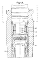
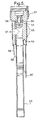
- Figure 1 shows the upper end of a cased well having a wellhead housing 20, in which casing hangers, including an uppermost production casing hanger 21 for, for example, 9 5/8" or 10 3/4", production casing is mounted in conventional manner.
- Figure 1 shows a conventional drilling BOP 22 having rams 23 and kill and choke lines 24 connected to the upper end of the housing 20 by a drilling connector 25.
- the duct 29 communicates through a conduit 31 between a depending portion of the body 27 and the housing 20, and through a conduit 32 passing through the production casing hanger 21, to the annulus surround the production casing.
- the duct 30 communicates through channels 33 formed in the radially inner surface of the nut 28, and hence to a void to be described.
- the cooperation between the gland nut 28 and body 27 of the adapter therefore acts as a valve which can open and close a passage up past the production casing hanger from the production casing annulus.
- a tool is run in through the BOP and, by means by radially projecting spring lugs engaging in the channels 33, rotates the gland nut 28 to the valve closed position shown on the right hand side on Figure 1A. The well is thus resealed and the drilling BOP 22 can temporarily be removed.
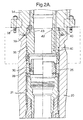
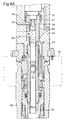
- the body of a tree spool 34 is then lowered on a tree installation tool 35, using conventional guide post location, or a guide funnel in case of deep water, until a spool tree mandrel 36 is guided into alignment with and slides as a close machined fit, into the upper end of the wellhead housing 20, to which the spool tree is then fixed via a production connector 37 and bolts 48.
- the mandrel 36 is actually a separate part which is bolted and sealed to the rest of the spool tree body.
- a weight set AX gasket 39 forming a metal to metal environmental seal is provided between the spool tree body and the wellhead housing 20.
- two sets of sealing rings 40 provide, in series with the environmental seal, a production fluid seal externally between the ends to the spool tree mandrel 36 to the spool tree body and to the wellhead housing 20.
- the intervening cavity can be tested through a test part 40A.
- the provision of the adapter 26 is actually optional, and in its absence the lower end of the spool tree mandrel 36 may form a production seal directly with the production casing hanger 21.
- the upper radially inner edge of the spool tree mandrel projects radially inwardly from the inner surface of the spool tree body above, to form a landing shoulder 42 and at least one machined key slot 43 is formed down through the landing shoulder.
- the drilling BOP 22 is reinstalled on the spool tree 34.
- the tool 44 used to set the adapter in Figure 1, having the spring dogs 45, is again run in until it lands on the shoulder 42, and the spring dogs 45 engage in the channels 33.
- the tool is then turned to screw the gland nut 28 down within the body 27 of the adapter 26 to the valve open position shown on the right hand side in Figure 1A. It is now safe to open the production casing annulus as the well is protected by the BOP.
- the next stage is to run in through the BOP and spool tree on an appropriate tool 44A a combined isolation and orientation sleeve 45.
- This lands on the shoulder 42 at the top of the spool tree mandrel and is rotated until a key on the sleeve drops into the mandrel key slot 43.
- This ensures precise angular orientation between the sleeve 45 and the spool tree 44, which is necessary, and in contrast to the angular orientation between the spool tree 34 and the wellhead casing, which is arbitrary.
- the sleeve 45 consists of an external cylindrical portion, an upper external surface of which is sealed by ring seals 46 to the spool tree 34, and the lower external surface of which is sealed by an annular seal 47 to the production casing hanger 21.
- a void 48 With which the channels 33, now defined radially inwardly by the sleeve 45, communicate.
- the void 48 in turn communicates via a duct 49 through the mandrel and body of the spool tree 34 to a lateral port.
- a lining which may be fixed in the cylindrical portion, or left after internal machining of the sleeve.
- This lining provides an orientation sleeve having an upper/edge forming a cam 50. The lowermost portion of the cam leads into a key slot 51.
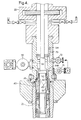
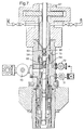
- a tubing string of production tubing 53 on a tubing hanger 54 is run in through the BOP 22 and spool tree 34 on a tool 55 until the tubing hanger lands by means of a keyed shoulder 56 on a landing in the spool tree and is locked down by a conventional mechanism 57.
- the tubing hanger 54 has a depending orientation sleeve 58 having an oblique lower edge forming a cam 59 which is complementary to the cam 50 in the sleeve 45 and, at the lower end of the cam, a downwardly projecting key 60 which is complementary to the key slot 51.
- the effect of the cams 50 and 59 is that, irrespective of the angular orientation of the tubing string as it is run in, the cams will cause the tubing hanger 54 to be rotated to its correct angular orientation relatively to the spool tree and the engagement of the key 60 in the key slot 51 will lock this relative orientation between the tubing hanger and spool tree, so that lateral production and tubing annulus fluid flow ports 61 and 62 in the tubing hanger 54 are in alignment with respective lateral production and tubing annulus fluid flow ports 63 and 64 through the wall of the spool tree.
- Metal to metal annulus seals 65 which are set by the weight of the tubing string, provide production fluid seals between the tubing hanger 54 and the spool tree 34.
- the keyed shoulder 56 of the tubing hanger lands in a complementary machined step in the spool tree 34 to ensure ultimate machined accuracy of orientation between the tubing hanger 54 and the spool tree 34.
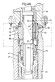
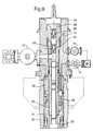
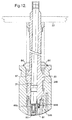
- Figure 7 shows the final step in the completion of the spool tree. This involves the running down on drill pipe 67 through the BOP, an internal isolation stopper 68 which seals within the top of the spool tree 34 and has an opening closed by an in situ wireline activated plug 69. The BOP can then be removed leaving the wellhead in production mode with double barrier isolation at the upper end of the spool tree provided by the plugs 66 and 69 and the stopper 68.
- the production fluid outlet is controlled by a master control valve 70 and pressure through the tubing annulus outlet ports 62 and 64 is controlled by an annulus master valve 71.
- Figure 9 shows valve circuitry associated with the completion and, in addition to the earlier views, shows a production fluid isolation valve 74, a tubing annulus valve 75 and a cross over valve 76.
- FIG. 1 to 9 The arrangement shown in Figures 1 to 9 is a mono production bore wellhead which can be accessed by a single wireline or drill pipe, and the external loop from the tubing annulus port to the void between the two plugs at the top of the spool tree avoids the need for wireline access to the tubing annulus bore.
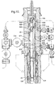
- Figure 10 corresponds to Figure 8 but shows a 51 ⁇ 2 inch x 23 ⁇ 8 inch dual production bore wellhead with primary and secondary production tubing 53A and 53B.
- Development and completion are carried out as with the monobore wellhead except that the spool tree 34A and tubing hanger 54A are elongated to accommodate lateral outlet ports 61A,63A for the primary production fluid flow from a primary bore 80 in the tubing hanger to a primary production master valve 70A, and lateral outlet ports 62A,64A for the secondary production fluid flow from a secondary bore 81 in the tubing hanger to a secondary production master valve 70B.
- the upper ends of the bores 80 and 81 are closed by wireline plugs 66A and 66B.
- a stopper 68A which closes the upper end of the spool tree 34A has openings, in alignment with the plugs 66A and 66B, closed by wireline plugs 69A and 69B.
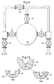
- Figures 11 and 12 show how a wireline 77 can be applied through a single drill pipe to activate selectively one or other of the two wireline plugs 66A and 66B in the production bores 80 and 81 respectively. This involves the use of a selected one of two connectors 82 and 83.
- a drilling BOP 22 is installed and the stopper 68A is removed. Thereafter the connector 82 or 83 is run in on the drill pipe or tubing until it lands in, and is secured and sealed to the spool tree 34A.
- Figure 13 shows how the correct angular orientation between the connector 82 or 83 and the spool tree 34A, is achieved by wing keys 84, which are guided by Y-shaped slots 85 in the upper inner edge of the spool tree, first to bring the connectors into the right angular orientation, and then to allow the relative axial movement between the parts to enable the stabbing function when the wireline connector engages with its respective pockets above plug 66A or 66B.
- two keys 84A and 84B are recommended.
- As the running tool is slowly rotated under a new control weight, it is essential that the tool only enters in one fixed orientation. To ensure this key 84A is wider than key 84B and its respective Y-shaped slots.
- one of the connectors 82 has a guide duct 86 which leads the wireline to the plug 66B whereas the other connector 83 has a similar guide duct 87 which leads the wireline to the other plug 66A.
Abstract
Description
- Conventionally, wells in oil and gas fields are built up by establishing a wellhead housing, and with a drilling blow out preventer stack (BOP) installed, drilling down to produce the well hole whilst successively installing concentric casing strings, which are cemented at the lower ends and sealed with mechanical seal assemblies at their upper ends. In order to convert the cased well for production, a tubing string is run in through the BOP and a hanger at its upper end landed in the wellhead. Thereafter the drilling BOP stack is removed and replaced by a Christmas tree having one or more production bores containing actuated valves and extending vertically to respective lateral production fluid outlet ports in the wall of the Christmas tree.
- This arrangement has involved problems which have, previously, been accepted as inevitable. Thus any operations down hole have been limited to tooling which can pass through the production bore, which is usually no more than five inch diameter, unless the Christmas tree is first removed and replaced by a BOP stack. However this involves setting plugs or valves, which may be unreliable by not having been used for a long time, down hole. The well is in a vulnerable condition whilst the Christmas tree and BOP stack are being exchanged and neither one is in position, which is a lengthy operation. Also, if it is necessary to pull the completion, consisting essentially of the tubing string on its hanger, the Christmas tree must first be removed and replaced by a BOP stack. This usually involves plugging and/or killing the well.
- A further difficulty which exists, particularly with subsea wells, is in providing the proper angular alignment between the various functions, such as fluid flow bores, and electrical and hydraulic lines, when the wellhead equipment, including the tubing hanger, Christmas tree, BOP stack and emergency disconnect devices are stacked up. Exact alignment is necessary if clean connections are to be made without damage as the devices are lowered into engagement with one another. This problem is exacerbated in the case of subsea wells as the various devices which are to be stacked up are run down onto guide posts or a guide funnel projecting upwardly from a guide base. The post receptacles which ride down on to the guide posts or the entry guide into the funnel do so with appreciable clearance. This clearance inevitably introduces some uncertainty in alignment and the aggregate misalignment when multiple devices are stacked, can be unacceptably large. Also the exact orientation will depend upon the precise positions of the posts or keys on a particular guide base and the guides on a particular running tool or BOP stack and these will vary significantly from one to another. Consequently it is preferable to ensure that the same running tools or BOP stack are used for the same wellhead, or a new tool or stack may have to be specially modified for a particular wellhead. Further misalignments can arise from the manner in which the guide base is bolted to the conductor casing of the wellhead.
- WO-A-86/01852 discloses and claims a wellhead with a tree body and a tubing hanger seated in the tree body, and with at least one lateral passage in the tree body and the tubing hanger providing access to the tubing.
- According to the present invention there is provideda wellhead assembly for controlling fluid flow in a subsea well having an outer casing supported at the subsea floor, the wellhead assembly comprising:
- a wellhead housing;
- a casing hanger supported by the wellhead housing at the subsea floor;
- an inner casing suspended within the wellhead housing by the casing hanger, the inner casing forming a casing annulus with the outer casing;
- a spool tree fixed and sealed to the wellhead housing (and having a spool tree bore forming a spool tree wall;
- a spool tree casing annulus port extending through the spool tree wall; and
- a member extending from the spool tree forming at least a portion of a fluid passageway communicating the spool tree casing annulus port (with the casing annulus.
-
- There is also provided a method of completing a cased well in which a production casing hanger is fixed and sealed by a seal assembly to a wellhead housing, with a BOP installed on the housing, the method comprising:
- removing the seal assembly and replacing it with a casing valve which is manipulatable between configurations in which a passage from the production casing annulus up past the production casing hanger is open or closed;
- with the passage closed, removing the BOP and fitting to the housing above the production casing hanger a spool tree having a spool tree bore and an internal landing for a tubing hanger;
- installing a BOP on the spool tree;
manipulating the valve to open the passage; and - inserting a sealing member, which seals to both the production casing hanger and spool tree to form a flow passageway communicating the passage with a production casing annulus pressure monitoring port in the spool tree.
-
- The type of tree to which the present invention relates is a spool tree which takes the place of a conventional Christmas tree, but which differs therefrom in having a comparatively large vertical through bore without any internal valves and at least large enough to accommodate the tubing completion. The advantages which are derived from the use of such spool tree are remarkable, in respect to safety and operational benefits.
- Thus, in workover situations the completion, consisting essentially of the tubing string, can be pulled through a BOP stack, without disturbing the spool tree and hence the pressure integrity of the well, whereafter full production casing drift access is provided to the well through the large bore in the spool tree. The BOP can be any appropriate workover BOP or drilling BOP of opportunity and does not have to be one specially set up for that well.
- Whereas modern well technology provides continuous access to the tubing annulus around the tubing string, it has generally been accepted as being difficult, if not impossible, to provide continuous venting and/or monitoring of the pressure in the production casing annulus, that is the annulus around the innermost casing string. This has been because the production casing annulus must be securely sealed whist the Christmas tree is fitted in place of the drilling BOP, and the Christmas tree has only been fitted after the tubing string and hanger has been run in, necessarily inside the production casing hanger, so that the production casing hanger is no longer accessible for the opening of a passageway from the production casing annulus. However, the new arrangement, wherein the spool tree is fitted before the tubing string is run in provides adequate protected access through the BOP and spool tree to the production casing hanger for controlling a passage from the production casing annulus.
- Other features of the assembly of the invention may be found in the subsidiary claims.
- Production casing annulus pressure monitoring can be set up by a method of completing a cased well in which a production casing hanger is fixed and sealed by a seal assembly to a wellhead housing, the method comprising, with a BOP installed on the housing, removing the seal assembly and replacing it with an adapter which is manipulatable between configurations in which a passages from the production casing annulus up past the production casing hanger is open or closed; with the passage closed, removing the BOP and fitting to the housing above the production casing hanger a spool tree having an internal landing for a tubing hanger; installing a BOP on the spool tree; running a tool down through the BOP and spool tree to manipulate the valve and open the passage; inserting through the BOP and spool tree an isolation sleeve, which seals to both the production casing and spool tree and hence defines between the sleeve and casing an annular void through which the passage leads to a production casing annulus pressure monitoring port in the spool tree; and running a tubing string down through the BOP and spool tree until the tubing hanger lands in the spool tree with lateral outlet ports in the tubing hanger and spool tree for production fluid flow, in alignment with one another.
- Pressure integrity between the wellhead housing and spool tree may be provided by two seals positioned in series one forming an environmental seal (such as an AX gasket) between the spool tree and the wellhead housing, and the other forming a production seal between the location mandrel and either the wellhead housing or the production casing hanger.
- During workover operations, the production casing annulus can be resealed by reversing the above steps, if necessary after setting plugs or packers down hole.
- Double barrier isolation, that is to say two barriers in series, are generally necessary for containing pressure in a well. If a spool tree is used instead of a conventional Christmas tree, there are no valves within the vertical production and annulus fluid flow bores within the tree, and alternative provision must be made for sealing the bore or bores through the top of the spool tree which provide for wire line or drill pipe access. Accordingly, at least one vertical production fluid bore in the tubing hanger is then sealed above the respective lateral production fluid outlet port by means of a removable plug, and the bore through the spool tree being sealed above the tubing hanger by means of a second removable plug.
- With this arrangement, the first plug, takes the function of a conventional swab valve, and may be a wireline set plug. The second plug could be a stopper set in the spool tree above the tubing hanger by, e.g., a drill pipe running tool. The stopper could contain at least one wireline retrievable plug which would allow well access when only wire line operations are called for. The second plug should seal and be locked internally into the spool tree as it performs a barrier to the well when a BOP or intervention module is deployed. A particular advantage of this double plug arrangement is that, as is necessary to satisfy authorities in some jurisdictions, the two independent barriers are provided in mechanically separate parts, namely the tubing hanger and its plug and the second plug in the spool tree.
- A further advantage arises if the workover port extends laterally through the wall of the spool tree from between the two plugs; a tubing annulus fluid port extends laterally through the wall of the spool tree from the tubing annulus; and these two ports through the spool tree are interconnected via an external flow line containing at least one actuated valve. The bore from the tubing annulus can then terminate at the port in the spool tree and no wireline access to the tubing annulus bore is necessary through the spool tree as the tubing annulus bore can be connected via the interplug void to choke or kill lines, i.e. a BOP annulus, so that downhole circulation is still available. It is then only necessary to provide wireline access at workover situations to the production bore or bores. This considerably simplifies workover BOP and/or riser construction. When used in conjunction with the plug at the top of the spool tree, the desirable double barrier isolation is provided by the spool tree plug over the tubing hanger, or workover valve from the production flow,.
- When the well is completed as a multi production bore well, in which the tubing hanger has at least two vertical production through bores each with a lateral production fluid flow port aligned with the corresponding port in the spool tree, at least two respective connectors may be provided for selective connection of a single bore wire line running tool to one or other of the production bores, each connector having a key for entering a complementary formation at the top of the spool tree to locate the connector in a predetermined angular orientation relatively to the spool tree. The same type of alternative connectors may be used for providing wireline or other running tool access to a selected one of a plurality of functional connections, e.g. electrical or hydraulic couplings, at the upper end of the tubing hanger.
- The development and completion of a subsea wellhead in accordance with the present invention are illustrated in the accompanying drawings, in which:
- Figures 1 to 8 are vertical axial sections showing successive steps in development and completion of the wellhead, the Figure numbers bearing the letter A being enlargements of part of the corresponding Figures of same number without the A:
- Figure 9 is a circuit diagram showing external connections to the spool 3;
- Figure 10 is a vertical axial section through a completed dual production bore well in production mode;
- Figures 11 and 12 are vertical axial sections showing alternative connectors to the upper end of the dual production bore wellhead during work over; and,
- Figure 13 is a detail showing the seating of one of the connectors in the spool tree.
-
- Figure 1 shows the upper end of a cased well having a
wellhead housing 20, in which casing hangers, including an uppermostproduction casing hanger 21 for, for example, 9 5/8" or 10 3/4", production casing is mounted in conventional manner. Figure 1 shows aconventional drilling BOP 22 havingrams 23 and kill and chokelines 24 connected to the upper end of thehousing 20 by adrilling connector 25. - As seen in more detail in Figure 1A, the usual mechanical seal assemblies between the
production casing hanger 21 and the surroundingwellhead housing 20 have been removed and replaced through the BOP with anadapter 26 consisting of an outerannular body part 27 and an innerannular gland nut 28 which has a screw threaded connection to thebody 27 so that it can be screwed between a lowered position shown on the right hand side of Figure 1A, in whichradial ducts body 27 andnut 28, are in communication with one another, and a raised position shown on the left hand side of Figure 1A, in which the ducts are out of communication with one another. Theduct 29 communicates through aconduit 31 between a depending portion of thebody 27 and thehousing 20, and through aconduit 32 passing through theproduction casing hanger 21, to the annulus surround the production casing. Theduct 30 communicates throughchannels 33 formed in the radially inner surface of thenut 28, and hence to a void to be described. The cooperation between thegland nut 28 andbody 27 of the adapter therefore acts as a valve which can open and close a passage up past the production casing hanger from the production casing annulus. After appropriate testing, a tool is run in through the BOP and, by means by radially projecting spring lugs engaging in thechannels 33, rotates thegland nut 28 to the valve closed position shown on the right hand side on Figure 1A. The well is thus resealed and thedrilling BOP 22 can temporarily be removed. - As shown in Figures 2 and 2A, the body of a
tree spool 34 is then lowered on atree installation tool 35, using conventional guide post location, or a guide funnel in case of deep water, until aspool tree mandrel 36 is guided into alignment with and slides as a close machined fit, into the upper end of thewellhead housing 20, to which the spool tree is then fixed via aproduction connector 37 andbolts 48. Themandrel 36 is actually a separate part which is bolted and sealed to the rest of the spool tree body. As seen particularly in Figure 2A a weight setAX gasket 39, forming a metal to metal environmental seal is provided between the spool tree body and thewellhead housing 20. In addition two sets of sealing rings 40 provide, in series with the environmental seal, a production fluid seal externally between the ends to thespool tree mandrel 36 to the spool tree body and to thewellhead housing 20. The intervening cavity can be tested through atest part 40A. The provision of theadapter 26 is actually optional, and in its absence the lower end of thespool tree mandrel 36 may form a production seal directly with theproduction casing hanger 21. As is also apparent from reasons which will subsequently become apparent, the upper radially inner edge of the spool tree mandrel projects radially inwardly from the inner surface of the spool tree body above, to form alanding shoulder 42 and at least one machinedkey slot 43 is formed down through the landing shoulder. - As shown in Figure 3, the
drilling BOP 22 is reinstalled on thespool tree 34. Thetool 44 used to set the adapter in Figure 1, having the spring dogs 45, is again run in until it lands on theshoulder 42, and the spring dogs 45 engage in thechannels 33. The tool is then turned to screw thegland nut 28 down within thebody 27 of theadapter 26 to the valve open position shown on the right hand side in Figure 1A. It is now safe to open the production casing annulus as the well is protected by the BOP. - The next stage, show in Figures 4 and 4A, is to run in through the BOP and spool tree on an
appropriate tool 44A a combined isolation andorientation sleeve 45. This lands on theshoulder 42 at the top of the spool tree mandrel and is rotated until a key on the sleeve drops into the mandrelkey slot 43. This ensures precise angular orientation between thesleeve 45 and thespool tree 44, which is necessary, and in contrast to the angular orientation between thespool tree 34 and the wellhead casing, which is arbitrary. Thesleeve 45 consists of an external cylindrical portion, an upper external surface of which is sealed byring seals 46 to thespool tree 34, and the lower external surface of which is sealed by anannular seal 47 to theproduction casing hanger 21. There is thus provided between thesleeve 45 and the surrounding wellhead casing 20 a void 48 with which thechannels 33, now defined radially inwardly by thesleeve 45, communicate. The void 48 in turn communicates via aduct 49 through the mandrel and body of thespool tree 34 to a lateral port. It is thus possible to monitor and vent the pressure in the production casing annulus through the passage provided past the production casing hanger via theconduits ducts channels 33, shown in Figure 1A, the void 48, theduct 49, and the lateral port in the spool tree. In the drawings, the radial portion of theduct 49 is shown apparently communicating with a tubing annulus, but this is draughtsman's licence and the ports from the two annuli are, in fact, angularly and radially spaced. - Within the cylindrical portion of the
sleeve 45 is a lining, which may be fixed in the cylindrical portion, or left after internal machining of the sleeve. This lining provides an orientation sleeve having an upper/edge forming acam 50. The lowermost portion of the cam leads into akey slot 51. - As shown in Figures 5,6 and 6A a tubing string of
production tubing 53 on atubing hanger 54 is run in through theBOP 22 andspool tree 34 on atool 55 until the tubing hanger lands by means of akeyed shoulder 56 on a landing in the spool tree and is locked down by aconventional mechanism 57. Thetubing hanger 54 has a dependingorientation sleeve 58 having an oblique lower edge forming acam 59 which is complementary to thecam 50 in thesleeve 45 and, at the lower end of the cam, a downwardly projecting key 60 which is complementary to thekey slot 51. The effect of thecams tubing hanger 54 to be rotated to its correct angular orientation relatively to the spool tree and the engagement of the key 60 in thekey slot 51 will lock this relative orientation between the tubing hanger and spool tree, so that lateral production and tubing annulusfluid flow ports tubing hanger 54 are in alignment with respective lateral production and tubing annulusfluid flow ports tubing hanger 54 and thespool tree 34. Provision is made in the top of thetubing hanger 54 for a wireline setplug 66. Thekeyed shoulder 56 of the tubing hanger lands in a complementary machined step in thespool tree 34 to ensure ultimate machined accuracy of orientation between thetubing hanger 54 and thespool tree 34. - Figure 7 shows the final step in the completion of the spool tree. This involves the running down on
drill pipe 67 through the BOP, aninternal isolation stopper 68 which seals within the top of thespool tree 34 and has an opening closed by an in situ wireline activatedplug 69. The BOP can then be removed leaving the wellhead in production mode with double barrier isolation at the upper end of the spool tree provided by theplugs stopper 68. The production fluid outlet is controlled by amaster control valve 70 and pressure through the tubingannulus outlet ports annulus master valve 71. The other side of this valve is connected, through aworkover valve 72 to alateral workover port 73 which extends through the wall of the spool tree to the void between theplugs valves ports - Figure 9 shows valve circuitry associated with the completion and, in addition to the earlier views, shows a production
fluid isolation valve 74, atubing annulus valve 75 and a cross overvalve 76. With this arrangement a wide variety of circulation can be achieved down hole using the production bore and tubing annulus, in conjunction with choke and kill lines extending from the BOP and through the usual riser string. All the valves are fail/safe closed if not actuated. - The arrangement shown in Figures 1 to 9 is a mono production bore wellhead which can be accessed by a single wireline or drill pipe, and the external loop from the tubing annulus port to the void between the two plugs at the top of the spool tree avoids the need for wireline access to the tubing annulus bore.
- Figure 10 corresponds to Figure 8 but shows a 5½ inch x 2⅜ inch dual production bore wellhead with primary and
secondary production tubing spool tree 34A andtubing hanger 54A are elongated to accommodatelateral outlet ports primary bore 80 in the tubing hanger to a primaryproduction master valve 70A, andlateral outlet ports secondary bore 81 in the tubing hanger to a secondaryproduction master valve 70B. The upper ends of thebores wireline plugs stopper 68A, which closes the upper end of thespool tree 34A has openings, in alignment with theplugs wireline plugs - Figures 11 and 12 show how a
wireline 77 can be applied through a single drill pipe to activate selectively one or other of the twowireline plugs connectors drilling BOP 22 is installed and thestopper 68A is removed. Thereafter theconnector spool tree 34A. Figure 13 shows how the correct angular orientation between theconnector spool tree 34A, is achieved bywing keys 84, which are guided by Y-shapedslots 85 in the upper inner edge of the spool tree, first to bring the connectors into the right angular orientation, and then to allow the relative axial movement between the parts to enable the stabbing function when the wireline connector engages with its respective pockets aboveplug keys connectors 82 has aguide duct 86 which leads the wireline to theplug 66B whereas theother connector 83 has asimilar guide duct 87 which leads the wireline to theother plug 66A.
Claims (61)
- A wellhead assembly for controlling fluid flow in a subsea well having an outer casing supported at the subsea floor, the wellhead assembly comprising:a wellhead housing (20);a casing hanger (21) supported by the wellhead housing (20) at the subsea floor;an inner casing suspended within the wellhead housing (20) by the casing hanger (21), the inner casing forming a casing annulus with the outer casing;a spool tree (34) fixed and sealed to the wellhead housing (20) and having a spool tree bore forming a spool tree wall;a spool tree casing annulus port (49) extending through the spool tree wall; anda member (45) extending from the spool tree forming at least a portion of a fluid passageway communicating the spool tree casing annulus port (49) with the casing annulus.
- The assembly of claim 1, wherein a portion of the fluid passageway extends through the space (48) created between the member (45), wellhead housing (20), casing hanger (21) and spool tree (34).
- The assembly of claim 1, further including a casing valve (26) controlling flow through the fluid passageway.
- The assembly of claim 3, further including a conduit (32) through the casing hanger (21) wherein the fluid passageway extends from the casing annulus port (49), through the space (48), the casing valve (26), and the casing hanger conduit (32), to the casing annulus.
- The assembly of claim 3, wherein the casing valve (26) is mounted on the casing hanger (21) to open and close the fluid passageway.
- The assembly of claim 3, wherein the casing valve (26) further includes a member (28) movably mounted on the casing valve (26), wherein the member (28) and casing valve (26) each have an annulus passageway with the member (28) having an open position where the annulus passageways are in fluid communication and a closed position when the annulus passageways are not in fluid communication.
- The assembly of claim 1, wherein the fluid passageway includes a conduit (32) through the casing hanger (21).
- The assembly of claim 7, wherein the casing hanger (21) is unsealed with the wellhead housing (20).
- The assembly of claim 1, wherein the spool tree (34) is sealed with the casing hanger (21) by member (45).
- The assembly of claim 9, wherein the member (45) includes a sealing member extending between the spool tree (34) and casing hanger (21) to form a portion of the fluid passageway.
- The assembly of claim 1, comprising:a metal-to-metal seal (39) for sealing the spool tree (34) and wellhead housing (20);the member (45) having first seals (46) on one end and second seals (47) on another end;the first seals (46) sealingly engaging the spool tree (34);the casing hanger (21) engaging the another end of the member (45); andthe second seals (47) sealingly engaging the casing hanger (21) for establishing a second seal to the metal-to-metal seal (39).
- The assembly of claim 11, wherein the member (45) creates an annular space (48) between the member (45) and the wellhead housing (20).
- The assembly of claim 12, wherein the fluid passageway extends through the space (48) and spool tree casing annulus port (49) to an exterior of the spool tree (34).
- The assembly of claim 11, wherein the member (45) includes a bore therethrough having a diameter no smaller than the diameter of the flowbore of the casing hanger (21).
- The assembly of claim 1, further including an internal valve (26) for controlling flow through the fluid passageway.
- The assembly of claim 1, further including means for monitoring or bleeding off fluid pressure in the casing annulus via the fluid passageway.
- The assembly of claim 1, wherein
the spool tree (34) is sealed to the wellhead housing (20) by a first fluid barrier; and
further including a second fluid barrier for the sealed connection between the spool tree (34) and wellhead housing (20) comprising:the member (45) having first seals (46) on one end and second seals (47) on another end;said one end extending into the spool tree (34) with the first seals (46) sealingly engaging the spool tree (34); andthe other end extending into the wellhead housing (20) with the second seals (47) sealingly engaging the casing hanger (21) for isolating the casing hanger (21). - The assembly of claim 1, further including an alignment member on the member (45) for aligning the member (45) within the spool tree (34).
- The assembly of claim 1, wherein the member (45) includes a support on the one end for supporting the member (45) within the spool tree (34) and the other end creates a sealing engagement with the casing hanger (21).
- The assembly of claim 1, wherein the spool tree (34) further includes at least a spool tree lateral production fluid outlet port (63) connected to a valve (70) and wherein the assembly further includes a tubing hanger landed (54) within the spool tree (34) at a predetermined angular position at which a tubing hanger lateral production fluid outlet port (61) in the tubing hanger (54) is in alignment with the spool tree lateral production fluid outlet port (63) in the spool tree (34),
- The assembly of claim 20, wherein the spool tree wall includes at least one spool tree tubing annulus port (64) therethrough;
the tubing hanger (54) supporting tubing within the spool tree bore, the tubing hanger (54) having at least one tubing hanger tubing annulus port (62);
the tubing having a tubing flowbore and forming a tubing annulus with the inner casing;
the tubing hanger lateral production fluid outlet port (61) providing fluid communication between the tubing flowbore and the spool tree lateral production fluid outlet port (63); and
the spool tree tubing annulus port (64) providing flow communication to the tubing annulus through the tubing hanger tubing annulus port (62). - The assembly of claim 21, further includes a connection on the spool tree (34) for controlling flow to the tubing annulus.
- The assembly of claim 20, wherein there are complementary guide means (50, 59) on the tubing hanger (54) and spool tree (34) to rotate the tubing hanger into the predetermined angular position relatively to the spool tree as the tubing hanger is lowered into the spool tree.
- The assembly of claim 23, wherein the guide means are provided by complementary oblique edge surfaces (50,59) one facing downwards on an orientation sleeve (58) depending from the tubing hanger (54) and the other facing upwards on the member (45) carried by the spool tree (34).
- An assembly according to any one of the claims 20,23, or 24, where the casing hanger (21) is carried in the wellhead housing (20) below the spool tree (34); the member (45) is sealed at its lower end to the casing hanger (21) and at its upper end to the spool tree (34) to define an annular void (48) between the member (45) and the housing (20); and an adapter (26) located in the annular space (48) and providing part of a passage from the casing annulus to the spool tree casing port (49) in the spool tree (34), the adapter (26) having a valve member (28) for opening and closing the passage, and the valve member (28) being operable through the spool tree (34) after withdrawal of the member (45) up through the spool tree (34).
- The assembly of claim 25, in which the valve is provided by a gland nut (28), which can be screwed up and down within a body (27) of the adapter (26) to bring parts (29,30) of the passage formed in the gland nut and adapter body, respectively, into and out of alignment with one another.
- An assembly according to claim 25 or claim 26, when dependent on claim 24, in which the orientation sleeve is provided within the member (45).
- An assembly according to any one of the claims 20 or 23-27, wherein the spool tree (34) has a downwardly depending location mandrel (36) which is a close sliding fit within a bore of the housing (20).
- The assembly of claim 28, in which an environmental seal (39) is provided between the spool tree (34) and the wellhead housing (20), and a production seal (40) is provided in series with the environmental seal between the location mandrel and either the wellhead housing (20) or the casing hanger (21).
- An assembly according to any of the claims 20 or 23-29, wherein at least one vertical production fluid bore in the tubing hanger (54) is sealed above the respective lateral production fluid outlet port (61) by means of a removable plug (66), and the spool tree bore through the spool tree (34) being sealed above the tubing hanger by means of a second removable plug (68).
- The assembly of claim 30, wherein the first plug is a wireline plug (66) and the second plus is a stopper (68) which contains at least one opening closed by a wireline plug (69).
- An assembly according to claim 30 or claim 31, wherein a workover port (73) extends laterally through the spool tree wall of the spool tree from between the two plugs (66, 68); a tubing annulus fluid port (64) extends laterally through the wall of the spool tree from the tubing annulus; and these two ports through the spool tree are interconnected via a line containing at least one valve (71, 72).
- An assembly according to any of the claims 20 or 23-32, in which the tubing hanger (54) has at least two separate functional connections at its upper end, separate connectors (82, 83) being provided for selective access of a single bore running tool to one of the functional connections, each connector having a key (84) for entering a complementary formation (85) at the top of the spool tree to locate the connector in a predetermined angular orientation relatively to the spool tree.
- An assembly according to claim 33, in which the tubing hanger (54) has at least two vertical production through bores (80, 81) each with a lateral production fluid flow port aligned with the corresponding port in the spool tree, at least two respective connectors (82, 83) being provided for selective connection of a single bore wire line running tool to one or other of the production bores, each connector having a key (84) for entering a complementary formation (85) at the top of the spool tree to locate the connector in a predetermined angular orientation relatively to the spool tree.
- An assembly according to any one of the claims 20 or 23-34, wherein the tubing hanger (54) has a shoulder (56) with an orientation key which cooperates with a landing in the spool tree (34) to provide final direct relative angular orientation between the tubing hanger and spool tree.
- The assembly of claim 20, wherein:wherein the second closure member (69) and the second seal (68) comprise a second pressure-containing barrier between the well and the environment; andthe spool tree (34), which extends axially through the spool tree bore, communicates with the spool tree lateral production fluid outlet port (63);the tubing hanger (54), which is supported in the spool tree bore, has a tubing hanger production bore and supports a tubing string which extends into the well and defines a tubing annulus surrounding the tubing string, the tubing hanger lateral production fluid outlet port (61) communicates with the tubing hanger production bore and the spool tree lateral production fluid outlet port (63); and includinga first seal (65) positioned between the tubing hanger (54) and the spool tree (34) above the tubing hanger lateral production fluid outlet port (61);a first closure member (66) positioned in the tubing hanger production bore above the tubing hanger lateral production fluid outlet port (61);wherein the first closure member (66) and the first seal (65) comprise a first pressure-containing barrier between the well and a surrounding environment;a second seal (68) which is positioned adjacent the tubing hanger (54) and spool tree (34) above the first seal (65) with the tubing hanger production bore extending therethrough;a second closure member (69) which is positioned in the tubing hanger production bore above the first closure member (66); and
wherein both the first and the second barriers are associated with the tubing hanger (54). - The assembly of claim 36, further comprising:an ancillary bore which extends generally axially through the tubing hanger from a lower end to an upper end of the tubing hanger; andan ancillary closure member positioned in the ancillary bore.
- The assembly of claim 37, wherein:the ancillary bore includes a generally lateral branch with a valve that is moveable to open and close the lateral branch.
- The assembly of claim 36 wherein the second seal (68) comprises:an annular body; andmeans for securing the body to the tubing spool (34).
- The assembly of claim 36, further comprising a connector with a seal stab for engaging the ancillary bore.
- The assembly of claim 40, wherein the connector further comprises:wherein fluid communication may be established between the ancillary bore and the conduit through the seal stab.a fluid bore extending through the connector and which is adapted to be connected to a conduit; andthe fluid bore communicating with a bore in the seal stab;
- The assembly of claim 37, further comprising:the tubing hanger tool having stabs received by the tubing hanger production bore and the ancillary bore in the tubing hanger.a tubing hanger tool which is removably connectable to the top of the tubing hanger in a predetermined orientation;the tubing hanger tool including a flow passageway therethrough and being sealed to the tubing spool; and
- The assembly of claim 36, further comprising:wherein the blowout preventer rams are adapted to sealingly engage the outer surface portion above the annulus passageway;a blowout preventer (22) which is removably connectable to the top of the tubing spool (34) and which includes a blowout preventer bore, a set of blowout preventer rams, and at least one choke and kill line that communicates with a portion of the blowout preventer bore which is located adjacent the blowout preventer rams; anda tubing hanger tool which is removably connectable to the top of the tubing hanger and which includes a cylindrical outer surface portion and a flowbore that communicates with the tubing hanger production bore;an annulus passageway (62, 64) which communicates the tubing annulus with the outer surface portion;
whereby fluid communication between the tubing annulus and the blowout preventer choke and kill line may be established through the annulus passageway and the portion of the blowout preventer bore which is located below the blowout preventer rams. - The assembly of claim 43, further including a conduit extending to the surface and in fluid communication with the tubing flowbore;
the annulus passageway in fluid communication with the choke and kill line;
the tubing hanger production bore in fluid communication with the tubing hanger tool flow passageway; and
fluid circulation paths being formed from the surface through the tubing hanger tool flow passageway and the choke and kill line between the tubing hanger flowbore and tubing annulus passageway, respectively, to selectively circulate downhole using the tubing flowbore and tubing annulus. - The assembly of claim 43, wherein the spool tree (34) further includes a workover passageway (73) in the spool tree wall, the workover passageway extending laterally into the spool tree bore;
a workover valve (72) disposed with the spool tree (34) for selective fluid circulation through the workover passageway;
the annulus passageway (62, 64) in fluid communication with the workover passageway (72);
the workover passageway (72) in fluid communication with the spool tree bore above the tubing hanger (54);
the spool tree bore being adapted for fluid communication with a choke and kill line; and
a fluid circulation pathway being formed between the spool tree bore, workover passageway (72), and annulus passageway (62,64) to selectively circulate downhole using said tubing flowbore and tubing annulus. - The assembly of claim 20, wherein:the spool tree (34) has a spool tree tubing annulus port (64);the tubing hanger (54) supporting tubing with a tubing flowbore and having a tubing hanger flow bore communicating with the spool tree bore, the tubing and inner casing (21) forming a tubing annulus;the tubing hanger (54) has a tubing hanger lateral production fluid outlet port (61) and tubing hanger tubing annulus port (64) communicating with the tubing annulus; and includingan annulus fluid flow path extending from the well and up through the tubing annulus, the tubing hanger tubing annulus port (62), and the spool tree tubing annulus port (64).
- The assembly of claim 46, further including a production fluid flow path extending from the well and up through the tubing flowbore, the tubing hanger flow bore, the tubing hanger lateral production fluid outlet port (61) and the spool tree lateral production fluid outlet port (63).
- The assembly of claim 46 further including a blowout preventer (22) mounted on the spool tree (34) having a conduit (55) in fluid communication with the tubing hanger and a circulating flow path extending from the well and up through the tubing flowbore, the tubing hanger flow bore, and the conduit.
- The assembly of claim 20, wherein
the spool tree (34) has a spool tree tubing annulus port (64); and including a conduit (32) extending between the casing hanger (20) the wellhead housing (20);
the tubing hanger (54) supporting tubing within the inner casing (21), the tubing having a tubing flowbore and forming a tubing annulus with the inner casing (21);
the tubing hanger (54) having a tubing hanger flow bore and a tubing hanger tubing annulus bore (62) in fluid communication with the spool tree bore and spool tree tubing annulus port (64), respectively; and
the tubing hanger tubing annulus bore (62) and spool tree tubing annulus port (64) communicating with the tubing annulus. - The assembly of claim 49, further including
a first fluid flow path extending from the well and through the tubing flowbore, tubing hanger flow bore, and spool tree bore;
a second fluid flow path extending from the well and through the tubing annulus, tubing hanger tubing annulus bore (62), and the spool tree tubing annulus port (64); and
a third fluid flow path extending from the well and through the casing annulus and the spool tree casing annulus port (49). - The assembly of claim 50, wherein the member (45) seals with the spool tree (34) and seals with the casing hanger (21), the member forming an exterior passageway between the casing annulus and the spool tree casing annulus port (49) and an interior passageway between the tubing annulus and the tubing hanger tubing annulus port (62).
- The assembly of claim 51 further including fluid communication between the annulus port and casing annulus via the fluid passageway, an annulus valve disposed on the spool tree for controlling flow through the annulus port.
- The assembly of claim 1, further including
a first string of casing to which the wellhead housing is secured, the inner casing being inside the first string of casing and extending below the production casing hanger (21);
a casing hanger communication passage passing through the inner casing hanger and in communication with the casing annulus, the member (45) forming a fluid passageway between the communication passage and the casing annulus port (49); and
a closure member connected to the production casing hanger to open and close the communication passage. - The assembly of claim 20, wherein
the tubing hanger has a tubing hanger production bore co-axial with the longitudinal axis of the spool tree and extending axially through the tubing hanger and an offset vertical passage (81) extending through the tubing hanger from a lower end to an upper end of the tubing hanger offset from the tubing hanger production bore, the offset vertical passage (81) having a lower end adapted to be in communication with a tubing annulus surrounding the string of tubing; and including
a first closure member (66A) installed in the tubing hanger production bore above the tubing hanger lateral production fluid outlet port (61A); and
a second closure member (66B) installed in the offset vertical passage. - The well production assembly according to claim 54, further comprising:a removable internal member (68A) which sealingly engages the bore of the spool tree (34A) above the tubing hanger (54A), the internal member (68A) having first and second vertical passages which are offset from and parallel to each other, the first vertical passage of the member (68A) aligning with the tubing hanger production bore, the second vertical passage of the member (68A) aligning with the offset vertical passage of the tubing hanger (54A);a third closure member (69A) installed in the first vertical passage of the internal member (68A); anda fourth closure member (69B) installed in the second vertical passage of the internal member (68A).
- The wellhead assembly of claim 54, further comprising:a lateral flow passage (62A) extending laterally from the offset vertical passage through the tubing hanger (54A) and having an opening at the exterior of the tubing hanger (54A); anda spool tree flow passage (64A) having an opening in the axial bore of the spool tree (34A) and extending laterally through the spool tree (34A) for sealingly registering with the opening of the lateral flow passage (62A) of the tubing hanger (54A).
- The assembly of claim 20, wherein
the lateral production fluid outlet port (63) has an inlet at the spool tree bore and extending laterally through the spool tree wall, the spool tree (34) being supported on a shoulder on the wellhead housing (20) with a seal (39) sealing the tubing hanger (54) and wellhead housing (20); and including
a tree auxiliary passage extending through the spool tree wall and having an auxiliary connector located at the shoulder; and
a mandrel (36) disposed in the wellhead housing (20) and having a mandrel auxiliary passage extending therethrough, the auxiliary connector in the spool tree sealingly mating with the auxiliary passage when the spool tree (34) lands on the wellhead housing (20) to communicate the tree auxiliary passage with the mandrel auxiliary passage. - The wellhead assembly of claim 57, wherein the mandrel auxiliary passage is used to test the seal between the wellhead housing (20) and spool tree (34).
- A method of completing a cased well in which a production casing hanger (21) is fixed and sealed by a seal assembly to a wellhead housing (20), with a BOP (22) installed on the housing, the method comprising:manipulating the valve to open the passage; andremoving the seal assembly and replacing it with a casing valve (26) which is manipulatable between configurations in which a passage from the production casing annulus up past the production casing hanger is open or closed;with the passage closed, removing the BOP and fitting to the housing above the production casing hanger a spool tree (34) having a spool tree bore and an internal landing for a tubing hanger (54);installing a BOP (22) on the spool tree;
inserting a sealing member (45), which seals to both the production casing hanger and spool tree to form a flow passageway (48) communicating the passage with a production casing annulus pressure monitoring port (49) in the spool tree. - The method of claim 59, further including running a tubing string down through the BOP and spool tree until the tubing hanger (54) lands in the spool tree with lateral outlet ports in the tubing hanger and spool tree for production fluid flow, in alignment with one another.
- The method of claim 60, further including:suspending tubing from a tubing hanger;supporting and sealing the tubing hanger within the spool tree for selective disposal below the blowout preventer;forming a common flow passageway between the blowout preventer and a portion of the spool tree bore above seals around the tubing hanger;extending a tubular member into the blowout preventer bore, attaching the tubular member to the tubing hanger, and closing the blowout preventer therearound;forming a flowpath through the tubing and the tubular member, forming an annular area between the tubular member and the production member in the common flow passageway and forming an annulus around the tubing below the tubing hanger;forming an annulus passageway from the annulus and through the wall of the production member;controlling flow through the annulus passageway by an annulus valve;forming a workover passageway from the annular area and through the wall of the production member;controlling flow through the workover passageway;providing fluid communication between the workover passageway and the annulus passageway; andcirculating fluid downhole using the flowpath, tubing annulus, annulus passageway, workover passageway, and annular area.
Priority Applications (1)
| Application Number | Priority Date | Filing Date | Title |
|---|---|---|---|
| EP02100394A EP1233145A3 (en) | 1992-06-01 | 1992-06-01 | Wellhead Assembly |
Applications Claiming Priority (4)
| Application Number | Priority Date | Filing Date | Title |
|---|---|---|---|
| EP99122799A EP0989283B1 (en) | 1992-06-01 | 1992-06-01 | Wellhead |
| EP92305014A EP0572732B1 (en) | 1992-06-01 | 1992-06-01 | Wellhead |
| EP96101005A EP0719905B2 (en) | 1992-06-01 | 1992-06-01 | Wellhead |
| EP02100394A EP1233145A3 (en) | 1992-06-01 | 1992-06-01 | Wellhead Assembly |
Related Parent Applications (1)
| Application Number | Title | Priority Date | Filing Date |
|---|---|---|---|
| EP99122799A Division EP0989283B1 (en) | 1992-06-01 | 1992-06-01 | Wellhead |
Publications (2)
| Publication Number | Publication Date |
|---|---|
| EP1233145A2 true EP1233145A2 (en) | 2002-08-21 |
| EP1233145A3 EP1233145A3 (en) | 2003-08-27 |
Family
ID=8211385
Family Applications (4)
| Application Number | Title | Priority Date | Filing Date |
|---|---|---|---|
| EP02100394A Withdrawn EP1233145A3 (en) | 1992-06-01 | 1992-06-01 | Wellhead Assembly |
| EP96101005A Expired - Lifetime EP0719905B2 (en) | 1992-06-01 | 1992-06-01 | Wellhead |
| EP92305014A Expired - Lifetime EP0572732B1 (en) | 1992-06-01 | 1992-06-01 | Wellhead |
| EP99122799A Revoked EP0989283B1 (en) | 1992-06-01 | 1992-06-01 | Wellhead |
Family Applications After (3)
| Application Number | Title | Priority Date | Filing Date |
|---|---|---|---|
| EP96101005A Expired - Lifetime EP0719905B2 (en) | 1992-06-01 | 1992-06-01 | Wellhead |
| EP92305014A Expired - Lifetime EP0572732B1 (en) | 1992-06-01 | 1992-06-01 | Wellhead |
| EP99122799A Revoked EP0989283B1 (en) | 1992-06-01 | 1992-06-01 | Wellhead |
Country Status (8)
| Country | Link |
|---|---|
| US (10) | US5544707A (en) |
| EP (4) | EP1233145A3 (en) |
| AU (1) | AU664634B2 (en) |
| CA (1) | CA2116873C (en) |
| DE (5) | DE69226630T2 (en) |
| MX (1) | MX9303273A (en) |
| NO (1) | NO940958D0 (en) |
| WO (1) | WO1993024730A1 (en) |
Cited By (9)
| Publication number | Priority date | Publication date | Assignee | Title |
|---|---|---|---|---|
| WO2005014971A1 (en) * | 2003-08-08 | 2005-02-17 | Woodside Energy Ltd | A method of suspending, completing and working over a well |
| WO2005103442A1 (en) * | 2004-04-24 | 2005-11-03 | Expro North Sea Limited | Plug setting and retrieving apparatus |
| WO2009079124A1 (en) * | 2007-12-14 | 2009-06-25 | Cameron International Corporation | Safety device for retrieving component within wellhead |
| WO2009120446A2 (en) * | 2008-03-25 | 2009-10-01 | Cameron International Corporation | Internal lockdown snubbing plug |
| CN102536161A (en) * | 2010-12-22 | 2012-07-04 | 韦特柯格雷公司 | Tubing hanger shuttle valve |
| US8613323B2 (en) | 2006-08-18 | 2013-12-24 | Cameron International Corporation | Wellhead assembly |
| US8939216B2 (en) | 2007-12-20 | 2015-01-27 | Cameron International Corporation | System and method for snubbing under pressure |
| GB2558267A (en) * | 2016-12-23 | 2018-07-11 | Statoil Petroleum As | Subsea wellhead monitoring and controlling |
| CN113187427A (en) * | 2021-04-28 | 2021-07-30 | 中国海洋石油集团有限公司 | Drilling-through type underwater horizontal Christmas tree and wellhead system |
Families Citing this family (161)
| Publication number | Priority date | Publication date | Assignee | Title |
|---|---|---|---|---|
| DE69226630T2 (en) | 1992-06-01 | 1998-12-24 | Cooper Cameron Corp | Wellhead |
| US5372199A (en) * | 1993-02-16 | 1994-12-13 | Cooper Industries, Inc. | Subsea wellhead |
| US5865250A (en) | 1994-08-23 | 1999-02-02 | Abb Vetco Gray Inc. | Fluid connector with check valve and method of running a string of tubing |
| US5465794A (en) * | 1994-08-23 | 1995-11-14 | Abb Vetco Gray Inc. | Hydraulic seal between tubing hanger and wellhead |
| GB9418088D0 (en) * | 1994-09-08 | 1994-10-26 | Exploration & Prod Serv | Horizontal subsea tree pressure compensated plug |
| GB9514526D0 (en) * | 1995-07-15 | 1995-09-13 | Expro North Sea Ltd | Lightweight intervention system for use with horizontal tree with internal ball valve |
| GB9514510D0 (en) * | 1995-07-15 | 1995-09-13 | Expro North Sea Ltd | Lightweight intervention system |
| GB9519202D0 (en) * | 1995-09-20 | 1995-11-22 | Expro North Sea Ltd | Single bore riser system |
| GB9604803D0 (en) * | 1996-03-07 | 1996-05-08 | Expro North Sea Ltd | High pressure tree cap |
| US6056059A (en) * | 1996-03-11 | 2000-05-02 | Schlumberger Technology Corporation | Apparatus and method for establishing branch wells from a parent well |
| US5819852A (en) * | 1996-03-25 | 1998-10-13 | Fmc Corporation | Monobore completion/intervention riser system |
| GB2319544B (en) | 1996-11-14 | 2000-11-22 | Vetco Gray Inc Abb | Tubing hanger and tree with horizontal flow and annulus ports |
| DE69622726T2 (en) | 1996-11-29 | 2002-11-28 | Cooper Cameron Corp | Wellhead assembly |
| GB2320937B (en) * | 1996-12-02 | 2000-09-20 | Vetco Gray Inc Abb | Horizontal tree block for subsea wellhead |
| US6050339A (en) * | 1996-12-06 | 2000-04-18 | Abb Vetco Gray Inc. | Annulus porting of horizontal tree |
| US5868204A (en) * | 1997-05-08 | 1999-02-09 | Abb Vetco Gray Inc. | Tubing hanger vent |
| US5988282A (en) * | 1996-12-26 | 1999-11-23 | Abb Vetco Gray Inc. | Pressure compensated actuated check valve |
| US6082460A (en) * | 1997-01-21 | 2000-07-04 | Cooper Cameron Corporation | Apparatus and method for controlling hydraulic control fluid circuitry for a tubing hanger |
| US5927403A (en) * | 1997-04-21 | 1999-07-27 | Dallas; L. Murray | Apparatus for increasing the flow of production stimulation fluids through a wellhead |
| BR9809438A (en) * | 1997-04-29 | 2000-06-13 | Fmc Corp | Equipment and method for underwater connection of trees to underwater sources |
| EP1021637B1 (en) * | 1997-10-07 | 2004-02-11 | FMC Technologies, Inc. | Slimbore subsea completion system and method |
| US6293345B1 (en) * | 1998-03-26 | 2001-09-25 | Dril-Quip, Inc. | Apparatus for subsea wells including valve passageway in the wall of the wellhead housing for access to the annulus |
| EP0952300B1 (en) * | 1998-03-27 | 2006-10-25 | Cooper Cameron Corporation | Method and apparatus for drilling a plurality of offshore underwater wells |
| US6202745B1 (en) * | 1998-10-07 | 2001-03-20 | Dril-Quip, Inc | Wellhead apparatus |
| GB2342668B (en) * | 1999-02-11 | 2000-10-11 | Fmc Corp | Large bore subsea christmas tree and tubing hanger system |
| US6253854B1 (en) * | 1999-02-19 | 2001-07-03 | Abb Vetco Gray, Inc. | Emergency well kill method |
| GB9911146D0 (en) * | 1999-05-14 | 1999-07-14 | Enhanced Recovery Limited Des | Method |
| US7111687B2 (en) | 1999-05-14 | 2006-09-26 | Des Enhanced Recovery Limited | Recovery of production fluids from an oil or gas well |
| GB2352258B (en) * | 1999-07-22 | 2003-09-17 | Plexus Ocean Syst Ltd | A wellhead arrangement |
| US6460621B2 (en) * | 1999-12-10 | 2002-10-08 | Abb Vetco Gray Inc. | Light-intervention subsea tree system |
| US20020100592A1 (en) | 2001-01-26 | 2002-08-01 | Garrett Michael R. | Production flow tree cap |
| GB2366027B (en) | 2000-01-27 | 2004-08-18 | Bell & Howell Postal Systems | Address learning system and method for using same |
| CA2399079C (en) | 2000-02-02 | 2007-01-02 | Fmc Technologies, Inc. | Non-intrusive pressure measurement device for subsea well casing annuli |
| GB2348659B (en) * | 2000-03-23 | 2001-03-28 | Fmc Corp | Tubing hanger saddle valve |
| AU2001245985A1 (en) | 2000-03-24 | 2001-10-08 | Fmc Corporation | Controls bridge for flow completion systems |
| US7025132B2 (en) * | 2000-03-24 | 2006-04-11 | Fmc Technologies, Inc. | Flow completion apparatus |
| US6494257B2 (en) * | 2000-03-24 | 2002-12-17 | Fmc Technologies, Inc. | Flow completion system |
| EP1278934B1 (en) | 2000-03-24 | 2005-08-24 | FMC Technologies, Inc. | Tubing hanger system with gate valve |
| EP1707737A1 (en) * | 2000-03-24 | 2006-10-04 | FMC Technologies, Inc. | Tubing head seal assembly |
| GB2361726B (en) * | 2000-04-27 | 2002-05-08 | Fmc Corp | Coiled tubing line deployment system |
| US7615893B2 (en) | 2000-05-11 | 2009-11-10 | Cameron International Corporation | Electric control and supply system |
| GB2362398B (en) | 2000-05-16 | 2002-11-13 | Fmc Corp | Device for installation and flow test of subsea completions |
| US6360822B1 (en) * | 2000-07-07 | 2002-03-26 | Abb Vetco Gray, Inc. | Casing annulus monitoring apparatus and method |
| GB2365890C (en) * | 2000-08-21 | 2006-02-07 | Fmc Corp | Multiple bore christmas tree outlet |
| US6695059B2 (en) * | 2000-10-23 | 2004-02-24 | Abb Vetco Gray Inc. | Mechanical anti-rotational feature for subsea wellhead housing |
| GB0027269D0 (en) | 2000-11-08 | 2000-12-27 | Donald Ian | Recovery of production fluids from an oil or gas well |
| US6484807B2 (en) | 2000-11-29 | 2002-11-26 | Cooper Cameron Corporation | Wellhead assembly for injecting a fluid into a well and method of using the same |
| US6516861B2 (en) | 2000-11-29 | 2003-02-11 | Cooper Cameron Corporation | Method and apparatus for injecting a fluid into a well |
| US6494267B2 (en) | 2000-11-29 | 2002-12-17 | Cooper Cameron Corporation | Wellhead assembly for accessing an annulus in a well and a method for its use |
| GB2370296B (en) | 2000-12-20 | 2002-11-06 | Fmc Corp | Wellhead system comprising a sliding sleeve seal |
| GB0100565D0 (en) * | 2001-01-10 | 2001-02-21 | 2H Offshore Engineering Ltd | Operating a subsea well |
| US6640902B2 (en) * | 2001-04-17 | 2003-11-04 | Fmc Technologies, Inc. | Nested stack-down casing hanger system for subsea wellheads |
| US7314088B2 (en) * | 2001-05-02 | 2008-01-01 | Shell Oil Company | System for retrieving a tubular element from a well |
| US6520263B2 (en) | 2001-05-18 | 2003-02-18 | Cooper Cameron Corporation | Retaining apparatus for use in a wellhead assembly and method for using the same |
| BR0209994B1 (en) | 2001-05-25 | 2011-01-11 | Horizontal spool tree assembly and method of supporting a production pipe column within a well from the tree assembly. | |
| GB2376485B (en) * | 2001-06-14 | 2003-08-27 | Kvaerner Oilfield Products Ltd | Annulus monitoring bleed |
| US6763891B2 (en) * | 2001-07-27 | 2004-07-20 | Abb Vetco Gray Inc. | Production tree with multiple safety barriers |
| BR0205883A (en) * | 2001-08-17 | 2003-11-18 | Kvaerner Oilfield Products Ltd | Wellhead housing installation, pressure monitoring / control system for an underwater wellhead arrangement and underwater wellhead arrangement |
| US6805200B2 (en) | 2001-08-20 | 2004-10-19 | Dril-Quip, Inc. | Horizontal spool tree wellhead system and method |
| US6659181B2 (en) * | 2001-11-13 | 2003-12-09 | Cooper Cameron Corporation | Tubing hanger with annulus bore |
| NO332032B1 (en) * | 2001-11-21 | 2012-05-29 | Vetco Gray Inc | Underwater wellhead assembly and method of completing an underwater well |
| BR0214464B1 (en) | 2001-11-27 | 2012-07-10 | subsea wellhead assembly, cutout injection subsea wellhead assembly and method for communicating with the annular space of the wellhead assembly. | |
| US7044227B2 (en) * | 2001-12-10 | 2006-05-16 | Vetco Gray Inc. | Subsea well injection and monitoring system |
| US20030121667A1 (en) * | 2001-12-28 | 2003-07-03 | Alfred Massie | Casing hanger annulus monitoring system |
| US6705401B2 (en) | 2002-01-04 | 2004-03-16 | Abb Vetco Gray Inc. | Ported subsea wellhead |
| CA2382904C (en) * | 2002-04-22 | 2005-04-12 | Daniel J. Riddell | Wellhead production pumping tree with access port |
| US6666266B2 (en) | 2002-05-03 | 2003-12-23 | Halliburton Energy Services, Inc. | Screw-driven wellhead isolation tool |
| US7063160B2 (en) * | 2002-07-30 | 2006-06-20 | Vetco Gray Inc. | Non-orienting tubing hanger system with a flow cage |
| WO2004016899A2 (en) * | 2002-08-16 | 2004-02-26 | Dril-Quip, Inc. | Horizontal spool tree wellhead system and method |
| WO2004025074A1 (en) * | 2002-08-22 | 2004-03-25 | Fmc Technologies, Inc. | Apparatus and method for installation of subsea well completion systems |
| GB2408280B (en) * | 2002-09-12 | 2007-03-07 | Dril Quip Inc | A system for well workover |
| GB2412679B (en) * | 2002-11-12 | 2005-12-21 | Vetco Gray Inc | Orientation system for a subsea well |
| US6966383B2 (en) * | 2002-12-12 | 2005-11-22 | Dril-Quip, Inc. | Horizontal spool tree with improved porting |
| GB2397312B (en) * | 2003-01-17 | 2005-07-27 | Fmc Technologies | Well completion system |
| US6966381B2 (en) * | 2003-04-09 | 2005-11-22 | Cooper Cameron Corporation | Drill-through spool body sleeve assembly |
| NO322829B1 (en) * | 2003-05-22 | 2006-12-11 | Fmc Kongsberg Subsea As | Resealable plug, valve tree with plug and well intervention procedure in wells with at least one plug |
| EP2233688B1 (en) | 2003-05-31 | 2013-07-17 | Cameron Systems (Ireland) Limited | Apparatus and method for recovering fluids from a well and/or injecting fluids into a well |
| US20040262010A1 (en) * | 2003-06-26 | 2004-12-30 | Milberger Lionel J. | Horizontal tree assembly |
| CA2476575C (en) * | 2003-08-05 | 2012-01-10 | Stream-Flo Industries Ltd. | Method and apparatus to provide electrical connection in a wellhead for a downhole electrical device |
| US7552762B2 (en) * | 2003-08-05 | 2009-06-30 | Stream-Flo Industries Ltd. | Method and apparatus to provide electrical connection in a wellhead for a downhole electrical device |
| US7296629B2 (en) * | 2003-10-20 | 2007-11-20 | Fmc Technologies, Inc. | Subsea completion system, and methods of using same |
| US7647595B2 (en) * | 2003-10-29 | 2010-01-12 | Oracle International Corporation | Efficient event notification in clustered computing environments |
| US7121346B2 (en) * | 2003-11-18 | 2006-10-17 | Cameron International Corporation | Intervention spool for subsea use |
| AU2005216412B2 (en) | 2004-02-26 | 2011-03-31 | Onesubsea Ip Uk Limited | Connection system for subsea flow interface equipment |
| US7331396B2 (en) * | 2004-03-16 | 2008-02-19 | Dril-Quip, Inc. | Subsea production systems |
| US20050242519A1 (en) * | 2004-04-29 | 2005-11-03 | Koleilat Bashir M | Wedge seal |
| GB2415720B (en) * | 2004-06-28 | 2007-04-11 | Dril Quip Inc | Pressure-compensated flow shut-off sleeve for wellhead and subsea well assembly including same |
| US7467663B2 (en) * | 2004-09-07 | 2008-12-23 | Dril-Quip, Inc. | High pressure wellhead assembly interface |
| DE602005022214D1 (en) * | 2004-10-06 | 2010-08-19 | Fmc Technologies | UNIVERSAL CONNECTION LIMIT AREA FOR UNDERWATER COMPLETING SYSTEMS |
| US7861789B2 (en) * | 2005-02-09 | 2011-01-04 | Vetco Gray Inc. | Metal-to-metal seal for bridging hanger or tieback connection |
| US7419001B2 (en) * | 2005-05-18 | 2008-09-02 | Azura Energy Systems, Inc. | Universal tubing hanger suspension assembly and well completion system and method of using same |
| CN101208495B (en) * | 2005-05-18 | 2013-03-20 | 阿古斯萨伯希股份有限公司 | Universal tubing hanger suspension assembly and well completion system and method of using same |
| US8286713B2 (en) * | 2005-05-18 | 2012-10-16 | Argus Subsea, Inc. | Oil and gas well completion system and method of installation |
| GB2432172B (en) * | 2005-11-09 | 2008-07-02 | Aker Kvaerner Subsea Ltd | Subsea trees and caps for them |
| EP1982042B1 (en) * | 2006-01-24 | 2018-07-04 | Helix Well Ops (U.K.) Limited | Bore selector |
| US7607485B2 (en) * | 2006-01-26 | 2009-10-27 | Vetco Gray Inc. | Tubing hanger and wellhead housing with mating tubing annulus passages |
| US7909103B2 (en) * | 2006-04-20 | 2011-03-22 | Vetcogray Inc. | Retrievable tubing hanger installed below tree |
| US7599469B2 (en) * | 2006-04-28 | 2009-10-06 | Cameron International Corporation | Non-intrusive pressure gage |
| US7798231B2 (en) * | 2006-07-06 | 2010-09-21 | Vetco Gray Inc. | Adapter sleeve for wellhead housing |
| US7699110B2 (en) * | 2006-07-19 | 2010-04-20 | Baker Hughes Incorporated | Flow diverter tool assembly and methods of using same |
| GB0618001D0 (en) | 2006-09-13 | 2006-10-18 | Des Enhanced Recovery Ltd | Method |
| US9127534B2 (en) | 2006-10-31 | 2015-09-08 | Halliburton Energy Services, Inc. | Cable integrity monitor for electromagnetic telemetry systems |
| GB0625191D0 (en) | 2006-12-18 | 2007-01-24 | Des Enhanced Recovery Ltd | Apparatus and method |
| GB0625526D0 (en) | 2006-12-18 | 2007-01-31 | Des Enhanced Recovery Ltd | Apparatus and method |
| WO2008103280A2 (en) * | 2007-02-16 | 2008-08-28 | Medtronic, Inc. | Delivery systems and methods of implantation for replacement prosthetic heart valves |
| US7743832B2 (en) * | 2007-03-23 | 2010-06-29 | Vetco Gray Inc. | Method of running a tubing hanger and internal tree cap simultaneously |
| US20090071656A1 (en) * | 2007-03-23 | 2009-03-19 | Vetco Gray Inc. | Method of running a tubing hanger and internal tree cap simultaneously |
| US8011436B2 (en) * | 2007-04-05 | 2011-09-06 | Vetco Gray Inc. | Through riser installation of tree block |
| US8047295B2 (en) * | 2007-04-24 | 2011-11-01 | Fmc Technologies, Inc. | Lightweight device for remote subsea wireline intervention |
| GB2468075B (en) * | 2007-11-05 | 2011-03-23 | Cameron Int Corp | Self-energizing annular seal |
| NO333955B1 (en) * | 2007-11-23 | 2013-10-28 | Fmc Kongsberg Subsea As | Underwater horizontal Christmas tree |
| US20090158298A1 (en) * | 2007-12-12 | 2009-06-18 | Abhishek Saxena | Database system and eventing infrastructure |
| WO2009076614A2 (en) | 2007-12-12 | 2009-06-18 | Cameron International Corporation | Function spool |
| US8899315B2 (en) * | 2008-02-25 | 2014-12-02 | Cameron International Corporation | Systems, methods, and devices for isolating portions of a wellhead from fluid pressure |
| US8851182B2 (en) * | 2008-03-28 | 2014-10-07 | Cameron International Corporation | Wellhead hanger shoulder |
| US8662184B2 (en) * | 2008-04-15 | 2014-03-04 | Cameron International Corporation | Multi-section tree completion system |
| GB0815035D0 (en) * | 2008-08-16 | 2008-09-24 | Aker Subsea Ltd | Wellhead annulus monitoring |
| WO2010062652A2 (en) * | 2008-10-28 | 2010-06-03 | Cameron International Corporation | Subsea completion with a wellhead annulus access adapter |
| NO329610B1 (en) * | 2008-12-02 | 2010-11-22 | West Oil Tools As | Wellhead with integrated safety valve and method of manufacture and use of the same |
| GB2466514B (en) * | 2008-12-24 | 2012-09-05 | Weatherford France Sas | Wellhead downhole line communication arrangement |
| US8602658B2 (en) * | 2010-02-05 | 2013-12-10 | Baker Hughes Incorporated | Spoolable signal conduction and connection line and method |
| US8397828B2 (en) * | 2010-03-25 | 2013-03-19 | Baker Hughes Incorporated | Spoolable downhole control system and method |
| US8794334B2 (en) | 2010-08-25 | 2014-08-05 | Cameron International Corporation | Modular subsea completion |
| GB2484298A (en) * | 2010-10-05 | 2012-04-11 | Plexus Ocean Syst Ltd | Subsea wellhead with adjustable hanger forming an annular seal |
| US8668020B2 (en) * | 2010-11-19 | 2014-03-11 | Weatherford/Lamb, Inc. | Emergency bowl for deploying control line from casing head |
| GB2486451B (en) * | 2010-12-15 | 2013-01-16 | Verderg Connectors Ltd | Connection apparatus and method |
| US20120152564A1 (en) * | 2010-12-16 | 2012-06-21 | Terry Peltier | Horizontal production tree and method of use thereof |
| US8997872B1 (en) * | 2012-02-22 | 2015-04-07 | Trendsetter Engineering, Inc. | Cap assembly for use with a tubing spool of a wellhead |
| US9376881B2 (en) * | 2012-03-23 | 2016-06-28 | Vetco Gray Inc. | High-capacity single-trip lockdown bushing and a method to operate the same |
| US9784063B2 (en) * | 2012-08-17 | 2017-10-10 | Onesubsea Ip Uk Limited | Subsea production system with downhole equipment suspension system |
| US9404332B2 (en) | 2012-10-08 | 2016-08-02 | Onesubsea Ip Uk Limited | Well system with an independently retrievable tree |
| US8973664B2 (en) * | 2012-10-24 | 2015-03-10 | Vetco Gray Inc. | Subsea wellhead stabilization using cylindrical sockets |
| US9279308B2 (en) | 2013-08-20 | 2016-03-08 | Onesubsea Llc | Vertical completion system including tubing hanger with valve |
| US9273531B2 (en) * | 2013-12-06 | 2016-03-01 | Ge Oil & Gas Uk Limited | Orientation adapter for use with a tubing hanger |
| US9506329B2 (en) * | 2014-02-28 | 2016-11-29 | Cameron International Corporation | Rotating hanger |
| US9376872B2 (en) * | 2014-03-12 | 2016-06-28 | Onesubsea Ip Uk Limited | Tubing hanger orientation spool |
| GB2541592B (en) * | 2014-06-09 | 2020-12-09 | Schlumberger Technology Bv | System and methodology using annulus access valve |
| US10309190B2 (en) * | 2014-07-23 | 2019-06-04 | Onesubsea Ip Uk Limited | System and method for accessing a well |
| MY181521A (en) * | 2014-07-25 | 2020-12-24 | Helix Energy Solutions Group Inc | Method of subsea containment and system |
| CN104227383A (en) * | 2014-09-26 | 2014-12-24 | 宁波旭升机械有限公司 | Oil pipe press mounting device |
| US9765593B2 (en) * | 2014-12-03 | 2017-09-19 | Ge Oil & Gas Uk Limited | Configurable subsea tree master valve block |
| US9341045B1 (en) * | 2014-12-03 | 2016-05-17 | Ge Oil & Gas Uk Limited | Configurable subsea tree master valve block |
| US9909380B2 (en) | 2015-02-25 | 2018-03-06 | Onesubsea Ip Uk Limited | System and method for accessing a well |
| US9523259B2 (en) * | 2015-03-05 | 2016-12-20 | Ge Oil & Gas Uk Limited | Vertical subsea tree annulus and controls access |
| EP3452686A4 (en) * | 2016-05-02 | 2020-05-27 | Cameron Technologies Limited | Drilling and production system components with wide flange bodies |
| GB2566418A (en) * | 2016-06-30 | 2019-03-13 | A Bowen Billy JR | Test-port activated tubing hanger control valve |
| US20180313187A1 (en) * | 2017-05-01 | 2018-11-01 | Schlumberger Technology Corporation | Single body choke line and kill line valves |
| US10900314B2 (en) * | 2017-12-21 | 2021-01-26 | Spoked Solutions LLC | Riser system |
| CN108086937A (en) * | 2018-01-12 | 2018-05-29 | 科莱斯(天津)电热科技有限公司 | A kind of high-pressure well mouth hanger controls total valve gear |
| US10989002B2 (en) | 2018-02-26 | 2021-04-27 | Innovex Downhole Solutions, Inc. | Cable pack-off apparatus for well having electrical submersible pump |
| US20200032607A1 (en) * | 2018-07-24 | 2020-01-30 | Ensco International Incorporated | Well reentry |
| GB2586965A (en) * | 2019-08-29 | 2021-03-17 | Ge Oil & Gas Uk Ltd | Wellhead apparatus, assembly and method for supporting downhole tubing |
| CA3165482A1 (en) * | 2019-12-20 | 2021-06-24 | Cameron Technologies Limited | System and method for setting a barrier in a well string |
| GB202011951D0 (en) * | 2020-07-31 | 2020-09-16 | Baker Hughes Energy Tech Uk Limited | Tubing head spool and method of drilling a well using the tubing head spool |
| GB2600771B (en) * | 2020-11-10 | 2023-03-01 | Aker Solutions As | Wellhead system |
| WO2022149983A1 (en) * | 2021-01-10 | 2022-07-14 | Ccb Subsea As | Kit and method for modification of a horizontal valve tree |
| US11434719B2 (en) | 2021-02-01 | 2022-09-06 | Saudi Arabian Oil Company | Tubing casing annulus valve |
| CN114517655A (en) * | 2021-12-27 | 2022-05-20 | 深圳市百勤石油技术有限公司 | Economic small-wellhead gas production tree system suitable for natural gas hydrate exploitation |
| US20230340856A1 (en) * | 2022-04-26 | 2023-10-26 | Conocophillips Company | Temporary suspension of completed hydrocarbon wells |
| US11873693B2 (en) * | 2022-05-31 | 2024-01-16 | Saudi Arabian Oil Company | Cutting a valve within a well stack |
| CN115306341B (en) * | 2022-10-12 | 2022-12-16 | 大庆市华禹石油机械制造有限公司 | Carbon dioxide drives gas production wellhead assembly that possesses corrosion protection performance |
Citations (1)
| Publication number | Priority date | Publication date | Assignee | Title |
|---|---|---|---|---|
| WO1986001852A1 (en) * | 1984-09-12 | 1986-03-27 | Britoil Plc | Underwater well equipment |
Family Cites Families (83)
| Publication number | Priority date | Publication date | Assignee | Title |
|---|---|---|---|---|
| US2094812A (en) † | 1937-10-05 | Flow control heab | ||
| US2118094A (en) * | 1937-04-12 | 1938-05-24 | Mcdonough James Moore | Combination casing head and christmas tree |
| US2148360A (en) * | 1937-12-30 | 1939-02-21 | Gray Tool Co | Oil well casing head and tubing hanger |
| US2590688A (en) * | 1946-11-14 | 1952-03-25 | Gray Tool Co | Well manifold |
| US2478628A (en) * | 1947-01-27 | 1949-08-09 | Shell Dev | Testing casing heads |
| US2889886A (en) * | 1956-01-23 | 1959-06-09 | Jay P Gould | Well head |
| US2954742A (en) * | 1957-04-29 | 1960-10-04 | Clifford C Williams | Water pump unit |
| US2951363A (en) * | 1957-09-20 | 1960-09-06 | Jersey Prod Res Co | Tool for testing well head equipment |
| US2965174A (en) * | 1958-01-27 | 1960-12-20 | Shell Oil Co | Off-shore well installation and method |
| US3041090A (en) * | 1959-04-28 | 1962-06-26 | Shell Oil Co | Pivoted tubing well connection |
| US3090640A (en) * | 1959-05-04 | 1963-05-21 | Shell Oil Co | Well casing and tubing suspension assembly |
| US3043371A (en) * | 1959-07-14 | 1962-07-10 | Rector Well Equipment Company | Valved tubing hanger |
| US3064735A (en) * | 1959-08-17 | 1962-11-20 | Shell Oil Co | Wellhead assembly lock-down apparatus |
| US3236308A (en) * | 1960-04-04 | 1966-02-22 | Richfield Oil Corp | Drilling apparatus and method |
| US3332481A (en) * | 1961-04-03 | 1967-07-25 | Richfield Oil Corp | Method of installing submarine drilling and production head |
| US3279536A (en) * | 1961-04-03 | 1966-10-18 | Richfield Oil Corp | Submarine drilling and production head and method of installing same |
| US3098525A (en) * | 1961-04-27 | 1963-07-23 | Shell Oil Co | Apparatus for installing and retrieving equipment from underwater wells |
| US3139932A (en) * | 1961-11-28 | 1964-07-07 | Shell Oil Co | Wellhead with tool diverter |
| US3305015A (en) * | 1963-09-20 | 1967-02-21 | Atlantic Richfield Co | Tubing head apparatus and method |
| US3310107A (en) * | 1963-10-23 | 1967-03-21 | Fmc Corp | Underwater well method and apparatus |
| US3331437A (en) * | 1965-01-06 | 1967-07-18 | Cameron Iron Works Inc | Wellhead assembly |
| US3299958A (en) * | 1965-04-02 | 1967-01-24 | Fmc Corp | Unitized well head |
| US3451481A (en) * | 1966-06-09 | 1969-06-24 | Rockwell Mfg Co | Dual suspension and seal |
| US3457992A (en) * | 1966-12-14 | 1969-07-29 | Atlantic Richfield Co | Underwater tubing head |
| US3414056A (en) * | 1967-03-06 | 1968-12-03 | Brown Oil Tools | Wellhead apparatus |
| US3437149A (en) * | 1967-05-31 | 1969-04-08 | Shaffer Tool Works | Cable feed-through means and method for well head constructions |
| US3454084A (en) * | 1967-10-10 | 1969-07-08 | Otis Eng Corp | Well head closure assembly |
| US3602303A (en) * | 1967-12-01 | 1971-08-31 | Amoco Prod Co | Subsea wellhead completion systems |
| US3552903A (en) * | 1968-06-28 | 1971-01-05 | Mobil Oil Corp | Subsea production satellite |
| US3545541A (en) * | 1968-08-08 | 1970-12-08 | Shell Oil Co | Wellhead assembly including diverter means |
| US3542125A (en) * | 1968-11-12 | 1970-11-24 | Otis Eng Corp | Well apparatus |
| US3662822A (en) * | 1969-05-12 | 1972-05-16 | Atlantic Richfield Co | Method for producing a benthonic well |
| NL7017510A (en) * | 1969-12-29 | 1971-07-01 | ||
| US3638732A (en) * | 1970-01-12 | 1972-02-01 | Vetco Offshore Ind Inc | Underwater wellhead electric connection apparatus for submerged electric motor driven well pumps and method of installation |
| US3628725A (en) * | 1970-01-16 | 1971-12-21 | Mattel Inc | Compact toy lap counter |
| US3638725A (en) * | 1970-05-15 | 1972-02-01 | Vetco Offshore Ind Inc | Direct drive casing hanger apparatus |
| US3971576A (en) | 1971-01-04 | 1976-07-27 | Mcevoy Oilfield Equipment Co. | Underwater well completion method and apparatus |
| CA1034488A (en) * | 1975-09-10 | 1978-07-11 | Mcevoy Oilfield Equipment Co. | Seal |
| GB1494301A (en) * | 1976-04-20 | 1977-12-07 | Gray Tool Co | Adjustable suspension of well tubing |
| SU625021A1 (en) * | 1977-01-06 | 1978-09-25 | Башкирский государственный научно-исследовательский и проектный институт нефтяной промышленности | Automatic valve device |
| US4116044A (en) * | 1977-04-28 | 1978-09-26 | Fmc Corporation | Packoff leak detector |
| US4130161A (en) * | 1977-09-06 | 1978-12-19 | Cameron Iron Works, Inc. | Underwater Christmas tree |
| US4154302A (en) * | 1977-10-31 | 1979-05-15 | Shafco Industries, Inc. | Cable feed-through method and apparatus for well head constructions |
| US4289199A (en) * | 1979-09-28 | 1981-09-15 | Combustion Engineering, Inc. | Wellhead sidewall electrical penetrator |
| IT1148764B (en) * | 1980-02-19 | 1986-12-03 | Saipem Spa | INFLANGEMENT FOR THE SUSPENSION OF COLUMNS OF COATING AND PRODUCTION PIPES FOR HIGH PRESSURE PETROLEUM OR GASES |
| US4436148A (en) * | 1981-04-27 | 1984-03-13 | Richard Maxwell | Chemical treatment for oil wells |
| US4455040A (en) * | 1981-08-03 | 1984-06-19 | Smith International, Inc. | High-pressure wellhead seal |
| US4491176A (en) * | 1982-10-01 | 1985-01-01 | Reed Lehman T | Electric power supplying well head assembly |
| CA1208123A (en) * | 1983-07-19 | 1986-07-22 | Barber Industries, Ltd. | Wellhead sealing system |
| US4541753A (en) * | 1983-07-22 | 1985-09-17 | Shell Oil Company | Subsea pipeline connection |
| US4569540A (en) * | 1983-12-29 | 1986-02-11 | Beson Technology, Inc. | Piping suspender with metal-to-metal seal |
| SU1244285A1 (en) * | 1984-11-30 | 1986-07-15 | Азербайджанский научно-исследовательский и проектно-конструкторский институт нефтяного машиностроения | Well-head connector |
| US4629003A (en) * | 1985-08-01 | 1986-12-16 | Baugh Benton F | Guilelineless subsea completion system with horizontal flowline connection |
| GB8617698D0 (en) * | 1986-07-19 | 1986-08-28 | Graser J A | Wellhead apparatus |
| GB8801850D0 (en) * | 1988-01-28 | 1988-02-24 | British Petroleum Co Plc | Tubing hanger shut-off mechanism |
| US4887672A (en) | 1988-12-16 | 1989-12-19 | Cameron Iron Works Usa, Inc. | Subsea wellhead with annulus communicating system |
| SU1659625A1 (en) * | 1989-07-25 | 1991-06-30 | Военизированная Часть По Предупреждению Возникновения И По Ликвидации Открытых Газовых И Нефтяных Фонтанов Северо-Восточного Промышленного Района | Wellhead setup equipment |
| GB8918844D0 (en) * | 1989-08-18 | 1989-09-27 | Shell Int Research | Wellhead assembly |
| US5143158A (en) | 1990-04-27 | 1992-09-01 | Dril-Quip, Inc. | Subsea wellhead apparatus |
| GB9014237D0 (en) * | 1990-06-26 | 1990-08-15 | Framo Dev Ltd | Subsea pump system |
| US5103915A (en) * | 1990-08-17 | 1992-04-14 | Abb Vetco Gray Inc. | Wellhead housing seal assembly for damaged sealing surfaces |
| US5141257A (en) * | 1991-09-23 | 1992-08-25 | Cooper Industries, Inc. | High preload mechanical connector |
| DE69226630T2 (en) | 1992-06-01 | 1998-12-24 | Cooper Cameron Corp | Wellhead |
| US5280706A (en) * | 1992-06-25 | 1994-01-25 | Thiokol Corporation | Composite/metal hybrid rocket motor case and methods for manufacturing |
| US5372199A (en) * | 1993-02-16 | 1994-12-13 | Cooper Industries, Inc. | Subsea wellhead |
| GB2286840B (en) * | 1994-02-10 | 1997-09-03 | Fmc Corp | Safety valve for horizontal tree |
| GB9418088D0 (en) * | 1994-09-08 | 1994-10-26 | Exploration & Prod Serv | Horizontal subsea tree pressure compensated plug |
| US5573336A (en) * | 1995-08-31 | 1996-11-12 | The Torrington Company | Seal for a spherical plain bearing |
| US5819852A (en) * | 1996-03-25 | 1998-10-13 | Fmc Corporation | Monobore completion/intervention riser system |
| GB2319544B (en) * | 1996-11-14 | 2000-11-22 | Vetco Gray Inc Abb | Tubing hanger and tree with horizontal flow and annulus ports |
| US6003602A (en) * | 1997-09-05 | 1999-12-21 | Kraerner Oilfield Products | Tree bore protector |
| EP1021637B1 (en) * | 1997-10-07 | 2004-02-11 | FMC Technologies, Inc. | Slimbore subsea completion system and method |
| US5975210A (en) * | 1997-12-31 | 1999-11-02 | Kvaerner Oilfield Products | Well completion system having a precision cut low profile helix |
| US6293345B1 (en) | 1998-03-26 | 2001-09-25 | Dril-Quip, Inc. | Apparatus for subsea wells including valve passageway in the wall of the wellhead housing for access to the annulus |
| AU2453300A (en) | 1999-02-11 | 2000-08-29 | Fmc Corporation | Subsea completion apparatus |
| US6470968B1 (en) * | 1999-10-06 | 2002-10-29 | Kvaerner Oifield Products, Inc. | Independently retrievable subsea tree and tubing hanger system |
| EP1278934B1 (en) | 2000-03-24 | 2005-08-24 | FMC Technologies, Inc. | Tubing hanger system with gate valve |
| US6494257B2 (en) | 2000-03-24 | 2002-12-17 | Fmc Technologies, Inc. | Flow completion system |
| AU2001245985A1 (en) | 2000-03-24 | 2001-10-08 | Fmc Corporation | Controls bridge for flow completion systems |
| US6626245B1 (en) * | 2000-03-29 | 2003-09-30 | L Murray Dallas | Blowout preventer protector and method of using same |
| US6360822B1 (en) | 2000-07-07 | 2002-03-26 | Abb Vetco Gray, Inc. | Casing annulus monitoring apparatus and method |
| US6516861B2 (en) | 2000-11-29 | 2003-02-11 | Cooper Cameron Corporation | Method and apparatus for injecting a fluid into a well |
| US6805200B2 (en) | 2001-08-20 | 2004-10-19 | Dril-Quip, Inc. | Horizontal spool tree wellhead system and method |
-
1992
- 1992-06-01 DE DE69226630T patent/DE69226630T2/en not_active Expired - Lifetime
- 1992-06-01 DE DE0719905T patent/DE719905T1/en active Pending
- 1992-06-01 EP EP02100394A patent/EP1233145A3/en not_active Withdrawn
- 1992-06-01 EP EP96101005A patent/EP0719905B2/en not_active Expired - Lifetime
- 1992-06-01 EP EP92305014A patent/EP0572732B1/en not_active Expired - Lifetime
- 1992-06-01 DE DE69232736T patent/DE69232736T2/en not_active Expired - Lifetime
- 1992-06-01 DE DE0989283T patent/DE989283T1/en active Pending
- 1992-06-01 EP EP99122799A patent/EP0989283B1/en not_active Revoked
- 1992-06-01 DE DE69231713T patent/DE69231713T3/en not_active Expired - Lifetime
-
1993
- 1993-05-28 WO PCT/US1993/005246 patent/WO1993024730A1/en active Application Filing
- 1993-05-28 AU AU44031/93A patent/AU664634B2/en not_active Expired
- 1993-05-28 US US08/204,397 patent/US5544707A/en not_active Expired - Lifetime
- 1993-05-28 CA CA002116873A patent/CA2116873C/en not_active Expired - Lifetime
- 1993-06-01 MX MX9303273A patent/MX9303273A/en unknown
-
1994
- 1994-03-16 NO NO940958A patent/NO940958D0/en unknown
-
1996
- 1996-07-12 US US08/679,560 patent/US6039119A/en not_active Expired - Lifetime
-
2000
- 2000-09-07 US US09/657,018 patent/US6547008B1/en not_active Expired - Fee Related
-
2003
- 2003-02-13 US US10/366,173 patent/US7093660B2/en not_active Expired - Fee Related
-
2004
- 2004-05-13 US US10/844,871 patent/US6991039B2/en not_active Expired - Fee Related
-
2005
- 2005-03-10 US US11/077,587 patent/US7314085B2/en not_active Expired - Fee Related
- 2005-03-10 US US11/078,121 patent/US7117945B2/en not_active Expired - Fee Related
-
2006
- 2006-07-25 US US11/459,836 patent/US7314086B2/en not_active Expired - Fee Related
- 2006-07-25 US US11/459,828 patent/US7308943B2/en not_active Expired - Fee Related
-
2007
- 2007-08-31 US US11/848,832 patent/US7500524B2/en not_active Expired - Fee Related
Patent Citations (1)
| Publication number | Priority date | Publication date | Assignee | Title |
|---|---|---|---|---|
| WO1986001852A1 (en) * | 1984-09-12 | 1986-03-27 | Britoil Plc | Underwater well equipment |
Cited By (28)
| Publication number | Priority date | Publication date | Assignee | Title |
|---|---|---|---|---|
| CN101586462B (en) * | 2003-08-08 | 2012-11-14 | 澳洲澳德赛能源有限公司 | Method of suspending, completing and working over a well |
| US7380609B2 (en) | 2003-08-08 | 2008-06-03 | Woodside Energy Limited | Method and apparatus of suspending, completing and working over a well |
| US7438135B2 (en) | 2003-08-08 | 2008-10-21 | Woodside Energy Ltd. | Method of suspending, completing and working over a well |
| WO2005014971A1 (en) * | 2003-08-08 | 2005-02-17 | Woodside Energy Ltd | A method of suspending, completing and working over a well |
| CN1860282B (en) * | 2003-08-08 | 2010-04-28 | 澳洲澳德赛能源有限公司 | Method of suspending, completing and working over a well |
| AP2132A (en) * | 2003-08-08 | 2010-07-11 | Woodside Energy Ltd | A method of suspending, completing and working over a well |
| US8028752B2 (en) | 2004-04-24 | 2011-10-04 | Expro North Sea Limited | Plug setting and retrieving apparatus |
| WO2005103442A1 (en) * | 2004-04-24 | 2005-11-03 | Expro North Sea Limited | Plug setting and retrieving apparatus |
| US8613323B2 (en) | 2006-08-18 | 2013-12-24 | Cameron International Corporation | Wellhead assembly |
| WO2009079124A1 (en) * | 2007-12-14 | 2009-06-25 | Cameron International Corporation | Safety device for retrieving component within wellhead |
| US9187969B2 (en) | 2007-12-14 | 2015-11-17 | Cameron International Corporation | Safety device for retrieving component within wellhead |
| GB2468813A (en) * | 2007-12-14 | 2010-09-22 | Cameron Int Corp | Safety device for retrieving component within wellhead |
| US9850743B2 (en) | 2007-12-14 | 2017-12-26 | Cameron International Corporation | Safety device for retrieving component within wellhead |
| GB2468813B (en) * | 2007-12-14 | 2012-09-19 | Cameron Int Corp | Safety device for retrieving component within wellhead |
| US8800646B2 (en) | 2007-12-14 | 2014-08-12 | Cameron International Corporation | Safety device for retrieving component within wellhead |
| US8939216B2 (en) | 2007-12-20 | 2015-01-27 | Cameron International Corporation | System and method for snubbing under pressure |
| GB2473355B (en) * | 2008-03-25 | 2013-03-06 | Cameron Int Corp | Internal Lockdown Snubbing Plug |
| US8701756B2 (en) | 2008-03-25 | 2014-04-22 | Cameron International Corporation | Internal lockdown snubbing plug |
| GB2473355A (en) * | 2008-03-25 | 2011-03-09 | Cameron Int Corp | Borehole plug |
| US9255460B2 (en) | 2008-03-25 | 2016-02-09 | Cameron International Corporation | Internal lockdown snubbing plug |
| WO2009120446A3 (en) * | 2008-03-25 | 2009-11-12 | Cameron International Corporation | Borehole plug |
| US10047579B2 (en) | 2008-03-25 | 2018-08-14 | Cameron International Corporation | Internal lockdown snubbing plug |
| WO2009120446A2 (en) * | 2008-03-25 | 2009-10-01 | Cameron International Corporation | Internal lockdown snubbing plug |
| CN102536161A (en) * | 2010-12-22 | 2012-07-04 | 韦特柯格雷公司 | Tubing hanger shuttle valve |
| US11035191B2 (en) | 2016-12-23 | 2021-06-15 | Equinor Energy As | Subsea wellhead monitoring and controlling |
| GB2558267B (en) * | 2016-12-23 | 2021-09-15 | Equinor Energy As | Subsea wellhead monitoring and controlling |
| GB2558267A (en) * | 2016-12-23 | 2018-07-11 | Statoil Petroleum As | Subsea wellhead monitoring and controlling |
| CN113187427A (en) * | 2021-04-28 | 2021-07-30 | 中国海洋石油集团有限公司 | Drilling-through type underwater horizontal Christmas tree and wellhead system |
Also Published As
Similar Documents
| Publication | Publication Date | Title |
|---|---|---|
| EP0989283B1 (en) | Wellhead | |
| US5971077A (en) | Insert tree | |
| US6062314A (en) | Tubing hanger and tree with horizontal flow and annulus ports | |
| US6076605A (en) | Horizontal tree block for subsea wellhead and completion method | |
| US8011436B2 (en) | Through riser installation of tree block | |
| WO2001055550A9 (en) | Crossover tree system | |
| WO2003050384A1 (en) | Production christmas tree | |
| US20010011593A1 (en) | Well completion system with an annular bypass and a solid stopper means | |
| GB2397312A (en) | Well completion system | |
| GB2472738A (en) | Wellhead assembly | |
| US9404332B2 (en) | Well system with an independently retrievable tree | |
| GB2351310A (en) | Tubing hanger and tree with horizontal flow and annulus ports |
Legal Events
| Date | Code | Title | Description |
|---|---|---|---|
| PUAI | Public reference made under article 153(3) epc to a published international application that has entered the european phase |
Free format text: ORIGINAL CODE: 0009012 |
|
| AC | Divisional application: reference to earlier application |
Ref document number: 989283 Country of ref document: EP Ref document number: 719905 Country of ref document: EP |
|
| AK | Designated contracting states |
Kind code of ref document: A2 Designated state(s): DE FR GB NL |
|
| PUAL | Search report despatched |
Free format text: ORIGINAL CODE: 0009013 |
|
| AK | Designated contracting states |
Designated state(s): DE FR GB NL |
|
| RIC1 | Information provided on ipc code assigned before grant |
Ipc: 7E 21B 33/035 A |
|
| 17P | Request for examination filed |
Effective date: 20030930 |
|
| AKX | Designation fees paid |
Designated state(s): DE FR GB NL |
|
| 17Q | First examination report despatched |
Effective date: 20081212 |
|
| STAA | Information on the status of an ep patent application or granted ep patent |
Free format text: STATUS: THE APPLICATION IS DEEMED TO BE WITHDRAWN |
|
| 18D | Application deemed to be withdrawn |
Effective date: 20131025 |