EP1233228A2 - Connector assembly for a fluid connection - Google Patents
Connector assembly for a fluid connection Download PDFInfo
- Publication number
- EP1233228A2 EP1233228A2 EP02076283A EP02076283A EP1233228A2 EP 1233228 A2 EP1233228 A2 EP 1233228A2 EP 02076283 A EP02076283 A EP 02076283A EP 02076283 A EP02076283 A EP 02076283A EP 1233228 A2 EP1233228 A2 EP 1233228A2
- Authority
- EP
- European Patent Office
- Prior art keywords
- plug
- male part
- bore
- connector assembly
- wall
- Prior art date
- Legal status (The legal status is an assumption and is not a legal conclusion. Google has not performed a legal analysis and makes no representation as to the accuracy of the status listed.)
- Withdrawn
Links
Images


Classifications
-
- F—MECHANICAL ENGINEERING; LIGHTING; HEATING; WEAPONS; BLASTING
- F16—ENGINEERING ELEMENTS AND UNITS; GENERAL MEASURES FOR PRODUCING AND MAINTAINING EFFECTIVE FUNCTIONING OF MACHINES OR INSTALLATIONS; THERMAL INSULATION IN GENERAL
- F16L—PIPES; JOINTS OR FITTINGS FOR PIPES; SUPPORTS FOR PIPES, CABLES OR PROTECTIVE TUBING; MEANS FOR THERMAL INSULATION IN GENERAL
- F16L55/00—Devices or appurtenances for use in, or in connection with, pipes or pipe systems
- F16L55/10—Means for stopping flow from or in pipes or hoses
- F16L55/115—Caps
-
- B—PERFORMING OPERATIONS; TRANSPORTING
- B65—CONVEYING; PACKING; STORING; HANDLING THIN OR FILAMENTARY MATERIAL
- B65D—CONTAINERS FOR STORAGE OR TRANSPORT OF ARTICLES OR MATERIALS, e.g. BAGS, BARRELS, BOTTLES, BOXES, CANS, CARTONS, CRATES, DRUMS, JARS, TANKS, HOPPERS, FORWARDING CONTAINERS; ACCESSORIES, CLOSURES, OR FITTINGS THEREFOR; PACKAGING ELEMENTS; PACKAGES
- B65D41/00—Caps, e.g. crown caps or crown seals, i.e. members having parts arranged for engagement with the external periphery of a neck or wall defining a pouring opening or discharge aperture; Protective cap-like covers for closure members, e.g. decorative covers of metal foil or paper
- B65D41/02—Caps or cap-like covers without lines of weakness, tearing strips, tags, or like opening or removal devices
-
- B—PERFORMING OPERATIONS; TRANSPORTING
- B65—CONVEYING; PACKING; STORING; HANDLING THIN OR FILAMENTARY MATERIAL
- B65D—CONTAINERS FOR STORAGE OR TRANSPORT OF ARTICLES OR MATERIALS, e.g. BAGS, BARRELS, BOTTLES, BOXES, CANS, CARTONS, CRATES, DRUMS, JARS, TANKS, HOPPERS, FORWARDING CONTAINERS; ACCESSORIES, CLOSURES, OR FITTINGS THEREFOR; PACKAGING ELEMENTS; PACKAGES
- B65D51/00—Closures not otherwise provided for
-
- B—PERFORMING OPERATIONS; TRANSPORTING
- B65—CONVEYING; PACKING; STORING; HANDLING THIN OR FILAMENTARY MATERIAL
- B65D—CONTAINERS FOR STORAGE OR TRANSPORT OF ARTICLES OR MATERIALS, e.g. BAGS, BARRELS, BOTTLES, BOXES, CANS, CARTONS, CRATES, DRUMS, JARS, TANKS, HOPPERS, FORWARDING CONTAINERS; ACCESSORIES, CLOSURES, OR FITTINGS THEREFOR; PACKAGING ELEMENTS; PACKAGES
- B65D75/00—Packages comprising articles or materials partially or wholly enclosed in strips, sheets, blanks, tubes, or webs of flexible sheet material, e.g. in folded wrappers
- B65D75/52—Details
- B65D75/58—Opening or contents-removing devices added or incorporated during package manufacture
- B65D75/5861—Spouts
- B65D75/5872—Non-integral spouts
-
- Y—GENERAL TAGGING OF NEW TECHNOLOGICAL DEVELOPMENTS; GENERAL TAGGING OF CROSS-SECTIONAL TECHNOLOGIES SPANNING OVER SEVERAL SECTIONS OF THE IPC; TECHNICAL SUBJECTS COVERED BY FORMER USPC CROSS-REFERENCE ART COLLECTIONS [XRACs] AND DIGESTS
- Y10—TECHNICAL SUBJECTS COVERED BY FORMER USPC
- Y10T—TECHNICAL SUBJECTS COVERED BY FORMER US CLASSIFICATION
- Y10T137/00—Fluid handling
- Y10T137/7722—Line condition change responsive valves
- Y10T137/7837—Direct response valves [i.e., check valve type]
- Y10T137/7879—Resilient material valve
- Y10T137/7888—With valve member flexing about securement
- Y10T137/7889—Sleeve
-
- Y—GENERAL TAGGING OF NEW TECHNOLOGICAL DEVELOPMENTS; GENERAL TAGGING OF CROSS-SECTIONAL TECHNOLOGIES SPANNING OVER SEVERAL SECTIONS OF THE IPC; TECHNICAL SUBJECTS COVERED BY FORMER USPC CROSS-REFERENCE ART COLLECTIONS [XRACs] AND DIGESTS
- Y10—TECHNICAL SUBJECTS COVERED BY FORMER USPC
- Y10T—TECHNICAL SUBJECTS COVERED BY FORMER US CLASSIFICATION
- Y10T137/00—Fluid handling
- Y10T137/8593—Systems
- Y10T137/87917—Flow path with serial valves and/or closures
- Y10T137/88054—Direct response normally closed valve limits direction of flow
Definitions
- the present invention concerns a connector assembly for a fluid connection according to the preamble of claim 1.
- Such a connector assembly is known, for instance, from US 4 375 864.
- the present invention provides a connector assembly according to claim 1.
- the connector assembly shown is intended for providing a fluid connection for fluids, gases, liquid substances, such as soap, cosmetic creams, soft drink syrup, etcetera.
- the connector assembly is also suitable for powders, in particular fine powders, having suitable flow properties to flow through such a connector, such as coffee powder and the like or toner powder for printers and copiers, etcetera.
- the female part of the connector assembly could then be part of a cartridge containing the powder, whereas the male part is part of the copier, printer or coffee machine.
- the connector assembly in fact comprises three components: a female part 1, a male part 2 which can be connected to it, and a plug 3.
- the female part 1 and the plug 3 are preferably manufactured as a unitary plastic object in a suitable mould by means of injection moulding.
- the male part 2 may also be manufactured as a plastic injection moulding product, but the male part 2 may also be made of metal, for instance stainless steel.
- the female part 1 has a body with a front end 5 and a rear end 6, with an axial and essentially cylindrical bore 7 extending through the body from the insert opening 4 for the male part 2 at the front end 5; this bore 7 is open at both ends.
- the edge at the transition from the front end 5 to the bore 7 is bevelled.
- the bore 7 is bounded by a ring wall 8 protruding from the body.
- the inner surface of the ring wall 8 forms a seat 9 for the plug 3 extending around the bore 7; this plug 3 serves for closing of the bore 7.
- the body of the female part 1 is especially suited for being welded or glued into the wall or a seam of a flexible plastic bag.
- the body of the female part 1 can also be laid out to be placed in the neck of a bottle or similar container, or in a stable ring-shaped holder fitted to a flexible bag.
- the latter design is known notably for so-called "bag-in-box" systems.
- the male part 2 has a tubular end piece 10 fitting into the bore 7 of the female part 1.
- a radially protruding stop ridge 11 of the male part 2 rests against the front end 5 of the female part 1.
- the male part 2 further comprises a tubular part 12, connected to the endpiece 10, with a ring-shaped projection 13 to facilitate handling of the male part 2.
- a hose coupling part 14 Connected to the tubular part 12 is a hose coupling part 14, enabling the male part 2 to be connected to a hose (not shown).
- the male part 2 contains an internal axial passage 15, indicated by dotted lines, for the fluid.
- the axial passage 15 is open at the end of the hose connection part 14 and is blind at the other end, which means that the passage 15 does not extend to the tip of the end piece 10 but stops at some distance of this.
- Within the male part 2 a number, in this case four, of cross passages 17 have been formed, which connect the axial passage 15 near its blind end with the perimeter of the male part 2.
- the male part 2 further comprises at its perimeter two diametrically opposed blocking devices 19, which extend parallel with the longitudinal axis of the male part 2 from the stop ridge 11 in the direction of the tip of the end piece 10.
- the female part 1 is provided with two diametrically opposed grooves 20, extending in axial direction along the bore 7, which serve to receive the blocking devices 19 when the male part 2 is inserted into the bore 7.
- the cooperation between the blocking devices 19 and the grooves 20 prevents the male part 2 from turning with respect to the female part 1 before the male element 2 is connected to the plug 3, as will be explained further on.
- the blocking devices 19 and the grooves 20 make it easier to insert the male part 2 into the bore 7.
- it is possible to obtain a kind of key so that a unique combination of a female part 1 and a male part 2 is obtained and a connection between non-matching male and female parts is prevented.
- the end piece 10 is further provided with a ring-shaped groove 22 to receive a sealing ring (not shown here to avoid confusion), which establishes the seal between the male part 2 and the female part 1 and also contributes to holding the male part 2 in the bore 7.
- the groove 22 is located in the area between the cross passages 17 and the stop ridge 11.
- a ridge can be provided at the outside of the male part 2.
- the tip of the end piece 10 of the male part 2 is constructed as an essentially conical head 23 with at its extremity an essentially cylindrical projection 24.
- the head 23 first has a locating surface 25, coned towards the outside, and contiguous with this a gripping surface 26, outwardly tapered at a small cone angle towards the outside.
- Contiguous with the gripping surface 26 is a shoulder surface 27, tapered towards the inside, which ends at the bottom of a recess, formed by the circumferential groove 28, between the head 23 and the part of the male part 2 that is provided with cross passages 17.
- the head 23 is provided with two diametrically opposed grooves 29, which extend from the tip of the end piece 10 to behind the head 23 and end in the groove-shaped recess 28.
- the plug 3 has a ring wall 31 and an end wall 32, which together enclose a cavity 33 in plug 3 which is open towards the insert opening 4; this cavity 33 is intended to receive the head 23 of the male part 2.
- the end wall 32 forms a cylindrical recess 34, whose diameter is adjusted to the diameter of the cylindrical projection 24 of the head 23. This complementary shape ensures that the plug 3 will remain seated in the correct position on the head 23 and will not tilt.
- the inner surface of the ring wall 31 is made complementary to the head 23 of the male part 2.
- the grooves 29 allow any substance present in the cavity 33 to escape via the grooves 29 when the head 23 enters the cavity 33.
- the plug 3 is connected with the body of the female part 1 by two flexible bodies 35.
- the bodies 35 ensure that the plug 3 cannot be separated from the female part 1. Furthermore, the length of the bodies 35 is such that when the connector assembly is in the position shown in Figure 1, the male part 2 can connect with the plug 3.
- the plug 3 has a radially expandable and compressible ring-shaped collar 40, which forms a whole with plug 3.
- the collar 40 has an interior surface 41, tapered from its free edge towards the inside, which connects to a shoulder surface 42 coned towards the outside, which in turn connects to the inside of ring wall 31.
- the collar 40 further has an exterior surface 44, tapered from its free edge towards the outside, which connects to a ring-shaped hooking surface 45 which is coned towards the inside, which in turn connects to the outer surface of ring wall 31.
- the plug 3 further has a sealing rim 46 located around the outside of the ring wall 31 and protruding towards the outside.
- the plug 3 also has an outward protruding ring-shaped stop surface 47 at the side of the sealing rim 46 which faces away from the collar 40.
- the ring wall 8 has an axial end face 50, against which the stop surface 47 of the plug 3 rests when the plug 3 is in its seat 9.
- the bore 7 has a first part with such a diameter that the male part 2 can be inserted in it with a light drive fit.
- the first part changes to a second part of bore 7 with a slightly smaller diameter.
- a shallow circumferential groove 53 in the bore 7 is located so that the sealing ring (not shown) of the male part 2, inserted fully into the female part 1, engages partly in this groove, so that on the one hand a reliable seal is obtained and on the other hand a kind of snap connection is obtained.
- the ring wall 8 has (see Fig. 4a), viewed from the end face 50 in the direction of the insert opening 4, a cylindrical sealing surface 54, with an inner diameter that is slightly smaller than the outer diameter of the sealing rim 46 of the plug 3. Consequently the plug 3 with its sealing rim 46 will fit tightly in the ring wall 8, thus establishing a radial seal.
- an inward coned transition surface 55 connects to the sealing surface 54; this transition surface 55 in its turn passes into an outward coned shoulder surface 56 of the bore 7.
- a transition surface 57 Connected to this conical shoulder surface 56 is a transition surface 57, coned outwards at a smaller angle, which connects to the second cylindrical part of the bore 7.
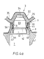
- Figure 4a shows in which way the plug 3, located in its seat, closes off the bore 7.
- the plug 3 rests with its stop surface 47 against the end face 50 of the ring wall 8 and presses the sealing rim 46 into the ring wall 8.
- the collar 40 is in its first position and the ring-shaped smooth hooking surface 45 of the plug 3 rests at an elastic prestress against the shoulder surface 56 of the bore 7. Note that the contact of the stop surface 47 against the end face 50 provides a second seal of the bore 7.
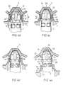
- FIG. 4b shows the situation when the head 23 of the male part 2 is inserted into the cavity 33 of the plug 3.
- the smallest diameter of the gripping surface 26 of the head 23 is smaller than the smallest diameter of the interior surface 41 in the first position of the collar 40 and as the taper angle of the interior surface 41 of the collar 40 is larger than the taper angle of the gripping surface 26 of the head 23, contact between the head 23 and the collar 40 is made especially at the location of the transition rim of the interior surface 41 to the shoulder surface 42 of the plug 3.
- Figure 4c shows the situation when the head 23 of the male part 2 is located entirely in the cavity 33 of the plug 3.
- the cylindrical projection 24 of the head 23 fits in the recess 34.
- the collar 40 has sprung back elastically from its second position as shown in Figure 4b to a third position.
- This third position is slightly further outward than the first position shown in Figure 4a, so the shoulder surface 42 of the plug 3 lies under prestress against the shoulder surface 27 of the head 23 and thus holds the head 23 in the plug 3 in a reliable way.
- the shoulder surface 56 of the bore 7 exerts a reaction force on the hooking surface 45 of the collar 40, which leads to an inward bending moment on the collar 40, again with respect to the thin connection of the collar 40 to the ring wall 31.
- the collar 40 can easily be compressed radially and so the diameter of the collar 40 decreases. Consequently the hooking surface 45 becomes more parallel to the axis of the male part 2, so that the force exerted via the hooking surface 45 on the ring wall 8 causes the ring wall 8 to expand radially to a greater degree.
- the collar 40 can pass the smallest diameter of the shoulder surface 56 of the bore 7 in a fourth position, pressed further inward, thus coming in the position shown in Figure 4d.
- the collar 40 is compressed radially, back to its fourth position, so that the force which is required to pull the head 23 from the plug 3 has become so much greater that first the plug 3 is pulled completely from its seat 9.
- the collar 40 subsequently passes the transition edge between the transition surface 55 and the shoulder surface 56 of the bore 7.
- the shoulder surface 27 of the head 23 exerts an outward bending moment on the collar 40; at that moment this collar 40 can easily expand again radially to its second position. As a result the head 23 can then be pulled from the plug 3 with a small force and subsequently the collar 40 springs back to its first position.
- the connector assembly it is possible to dimension as desired the axial force required during the different phases of connecting and disconnecting the male and female parts. For instance, it is possible to keep the axial force essentially constant during all the phases described above. In particular it is possible with the connector assembly described here that the axial force required to connect the male part 2 with the plug 3 is essentially equal to the axial force required to push the plug 3 subsequently from the bore 7.
- the cross section of the collar 40 is not uniform along its entire perimeter, but is built up from segments which are separated from each other by axial dividing seams or are connected to each other by thin bridging parts designed as thin film.
- the collar 40 may also be replaced by several discrete hooking fingers around the perimeter of the plug 3.
- Figure 5 shows one end, to be inserted into a female part, of a preferred embodiment of the male part 100 according to the invention.
- the male part 100 is very similar to the male part 2 described earlier, to which reference is made here, and can also be used in combination with the female part 1.
- the male part 100 is provided with an internal closing part, as will be explained below.
- the male part 100 has an internal axial passage 101 for a liquid, which is open on one end and is made blind at the tip of the insert end, and ends at an end wall 103.
- Several cross passages 105 have been provided, in this case four around the perimeter of the male part 100, each extending from the outer surface of the male part 100 to an outlet in the axial passage 101.
- a closing body 110 is fitted, which is shown separately in Figure 5.
- the closing body 110 is essentially cup-shaped with a flexible ring wall 111, which is intended to lie under prestress against the interior wall of the axial passage 101, thereby closing off the outlets of the cross passages 105.
- the flexible ring wall 111 can bend radially inward so as to provide a passage for the liquid.
- a suitable design of the closing body 110 makes it possible to choose the prestress with which the ring wall 111 presses against the axial passage 101 and the rigidity of the ring wall 111 in such a way that a passage is only created when there is a certain pressure difference between the inside and the outside of the ring wall 111.
- the closing body 110 acts as a non-return valve.
- the closing body 110 has a cross wall 112, transverse to the flexible ring wall 111, with a central opening in it (not discernible here).
- the closing body 110 can be removed from the male part 100 for cleaning or changing.
- Moulded to the end wall 103 of the axial passage 101 is a shank 114 with two diametrically opposed radial projections 115 at some distance from the end wall 103.
- the shank 114 protrudes through the opening in the cross wall 112 of the closing body 110, so that the projections 115 hook behind the cross wall 112 of the closing body 110.
- the closing body 110 is preferably an undivided object of a suitable rubber, silicone or elastomer and can be manufactured by injection moulding. As the closing body covers the outlets of the cross passages 105 the chance of undesired contamination of the axial passage, or a substance present in this, is minimal. It is also possible with this closing body 110 to prevent the presence of undesired air when making the connection with a suitable female part.
Abstract
Description
- The present invention concerns a connector assembly for a fluid connection according to the preamble of
claim 1. - Such a connector assembly is known, for instance, from US 4 375 864. The present invention provides a connector assembly according to
claim 1. - Other advantageous embodiments are described in claims and the description given below.
- The present invention will now be explained on the basis of the drawing. The figures show:
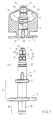
- Fig. 1 schematically, partly in cross-section, the parts of a preferred embodiment for the connector assembly according to the invention;
- Fig. 2 schematically, the connector assembly of Fig. 1, with the plug closing off the bore in the female part and the male part inserted in the female part and the plug;
- Fig. 3 schematically, the connector assembly of Fig. 1, with the plug free from the bore in the female part and borne by the male part;
- Figs. 4a-e: in cross-section, different successive stages of making a fluid connection with the connector assembly of Fig. 1;
- Fig. 5 in perspective, a preferred embodiment of the male part of the connector assembly according to the invention.
-
- Refering to Figures 1, 2, 3 and 4a-e first the construction and operation of a preferred embodiment of the connector assembly according to the invention will be explained. The connector assembly shown is intended for providing a fluid connection for fluids, gases, liquid substances, such as soap, cosmetic creams, soft drink syrup, etcetera. The connector assembly is also suitable for powders, in particular fine powders, having suitable flow properties to flow through such a connector, such as coffee powder and the like or toner powder for printers and copiers, etcetera. The female part of the connector assembly could then be part of a cartridge containing the powder, whereas the male part is part of the copier, printer or coffee machine.
- The connector assembly in fact comprises three components: a
female part 1, amale part 2 which can be connected to it, and aplug 3. Thefemale part 1 and theplug 3 are preferably manufactured as a unitary plastic object in a suitable mould by means of injection moulding. Themale part 2 may also be manufactured as a plastic injection moulding product, but themale part 2 may also be made of metal, for instance stainless steel. - The
female part 1 has a body with afront end 5 and arear end 6, with an axial and essentiallycylindrical bore 7 extending through the body from theinsert opening 4 for themale part 2 at thefront end 5; thisbore 7 is open at both ends. The edge at the transition from thefront end 5 to thebore 7 is bevelled. At therear end 6 thebore 7 is bounded by aring wall 8 protruding from the body. The inner surface of thering wall 8 forms aseat 9 for theplug 3 extending around thebore 7; thisplug 3 serves for closing of thebore 7. - The body of the
female part 1 is especially suited for being welded or glued into the wall or a seam of a flexible plastic bag. The body of thefemale part 1 can also be laid out to be placed in the neck of a bottle or similar container, or in a stable ring-shaped holder fitted to a flexible bag. The latter design is known notably for so-called "bag-in-box" systems. - The
male part 2 has atubular end piece 10 fitting into thebore 7 of thefemale part 1. When themale part 2 has been fully inserted into thefemale part 1, as shown in Figure 3, a radially protrudingstop ridge 11 of themale part 2 rests against thefront end 5 of thefemale part 1. Themale part 2 further comprises atubular part 12, connected to theendpiece 10, with a ring-shaped projection 13 to facilitate handling of themale part 2. - Connected to the
tubular part 12 is ahose coupling part 14, enabling themale part 2 to be connected to a hose (not shown). Themale part 2 contains an internalaxial passage 15, indicated by dotted lines, for the fluid. Theaxial passage 15 is open at the end of thehose connection part 14 and is blind at the other end, which means that thepassage 15 does not extend to the tip of theend piece 10 but stops at some distance of this. Within the male part 2 a number, in this case four, ofcross passages 17 have been formed, which connect theaxial passage 15 near its blind end with the perimeter of themale part 2. - The
male part 2 further comprises at its perimeter two diametrically opposedblocking devices 19, which extend parallel with the longitudinal axis of themale part 2 from thestop ridge 11 in the direction of the tip of theend piece 10. - The
female part 1 is provided with two diametrically opposedgrooves 20, extending in axial direction along thebore 7, which serve to receive theblocking devices 19 when themale part 2 is inserted into thebore 7. The cooperation between the blockingdevices 19 and thegrooves 20 prevents themale part 2 from turning with respect to thefemale part 1 before themale element 2 is connected to theplug 3, as will be explained further on. Moreover, the blockingdevices 19 and thegrooves 20 make it easier to insert themale part 2 into thebore 7. In addition, by varying the number of blocking devices and grooves, as well as their positions and shapes, it is possible to obtain a kind of key, so that a unique combination of afemale part 1 and amale part 2 is obtained and a connection between non-matching male and female parts is prevented. - The
end piece 10 is further provided with a ring-shaped groove 22 to receive a sealing ring (not shown here to avoid confusion), which establishes the seal between themale part 2 and thefemale part 1 and also contributes to holding themale part 2 in thebore 7. Thegroove 22 is located in the area between thecross passages 17 and thestop ridge 11. In a variant not shown here, instead of thegroove 22 with a sealing ring a ridge can be provided at the outside of themale part 2. - The tip of the
end piece 10 of themale part 2 is constructed as an essentiallyconical head 23 with at its extremity an essentiallycylindrical projection 24. In the direction away from the tip thehead 23 first has a locatingsurface 25, coned towards the outside, and contiguous with this agripping surface 26, outwardly tapered at a small cone angle towards the outside. Contiguous with thegripping surface 26 is ashoulder surface 27, tapered towards the inside, which ends at the bottom of a recess, formed by thecircumferential groove 28, between thehead 23 and the part of themale part 2 that is provided withcross passages 17. Thehead 23 is provided with two diametrically opposedgrooves 29, which extend from the tip of theend piece 10 to behind thehead 23 and end in the groove-shaped recess 28. - The
plug 3 has aring wall 31 and anend wall 32, which together enclose acavity 33 inplug 3 which is open towards theinsert opening 4; thiscavity 33 is intended to receive thehead 23 of themale part 2. Theend wall 32 forms acylindrical recess 34, whose diameter is adjusted to the diameter of thecylindrical projection 24 of thehead 23. This complementary shape ensures that theplug 3 will remain seated in the correct position on thehead 23 and will not tilt. Similarly, the inner surface of thering wall 31 is made complementary to thehead 23 of themale part 2. Thegrooves 29 allow any substance present in thecavity 33 to escape via thegrooves 29 when thehead 23 enters thecavity 33. - The
plug 3 is connected with the body of thefemale part 1 by twoflexible bodies 35. Thebodies 35 ensure that theplug 3 cannot be separated from thefemale part 1. Furthermore, the length of thebodies 35 is such that when the connector assembly is in the position shown in Figure 1, themale part 2 can connect with theplug 3. - At the end of
plug 3 which faces theinsert opening 4 of thefemale part 1, theplug 3 has a radially expandable and compressible ring-shaped collar 40, which forms a whole withplug 3. Thecollar 40 has aninterior surface 41, tapered from its free edge towards the inside, which connects to ashoulder surface 42 coned towards the outside, which in turn connects to the inside ofring wall 31. Thecollar 40 further has anexterior surface 44, tapered from its free edge towards the outside, which connects to a ring-shaped hooking surface 45 which is coned towards the inside, which in turn connects to the outer surface ofring wall 31. - The
plug 3 further has a sealingrim 46 located around the outside of thering wall 31 and protruding towards the outside. Theplug 3 also has an outward protruding ring-shaped stop surface 47 at the side of the sealingrim 46 which faces away from thecollar 40. - The
ring wall 8 has anaxial end face 50, against which thestop surface 47 of theplug 3 rests when theplug 3 is in itsseat 9. Viewed in the insert direction of themale part 2, thebore 7 has a first part with such a diameter that themale part 2 can be inserted in it with a light drive fit. - At
reference number 51 the first part changes to a second part ofbore 7 with a slightly smaller diameter. A shallowcircumferential groove 53 in the bore 7 (see Fig. 1) is located so that the sealing ring (not shown) of themale part 2, inserted fully into thefemale part 1, engages partly in this groove, so that on the one hand a reliable seal is obtained and on the other hand a kind of snap connection is obtained. - The
ring wall 8 has (see Fig. 4a), viewed from theend face 50 in the direction of theinsert opening 4, acylindrical sealing surface 54, with an inner diameter that is slightly smaller than the outer diameter of the sealingrim 46 of theplug 3. Consequently theplug 3 with its sealingrim 46 will fit tightly in thering wall 8, thus establishing a radial seal. - Viewed in the same direction an inward
coned transition surface 55 connects to the sealingsurface 54; thistransition surface 55 in its turn passes into an outward conedshoulder surface 56 of thebore 7. Connected to thisconical shoulder surface 56 is atransition surface 57, coned outwards at a smaller angle, which connects to the second cylindrical part of thebore 7. - On the basis of Figures 4a-4e the operation of the connector assembly will be explained. It should be noted that for the sake of clarity not all of the reference numbers mentioned in the description have been given; in these cases the reference numbers can be found in one of the other figures 4a-e.
- Figure 4a shows in which way the
plug 3, located in its seat, closes off thebore 7. Theplug 3 rests with itsstop surface 47 against theend face 50 of thering wall 8 and presses the sealingrim 46 into thering wall 8. In Figure 4a thecollar 40 is in its first position and the ring-shaped smooth hookingsurface 45 of theplug 3 rests at an elastic prestress against theshoulder surface 56 of thebore 7. Note that the contact of thestop surface 47 against theend face 50 provides a second seal of thebore 7. In this first position of thecollar 40, between theexterior surface 44 of thecollar 40 and thetransition surface 57 of the bore 7 a space is present whose size in a radial sense increases from theshoulder 56 towards the insert opening 4.Figure 4b shows the situation when thehead 23 of themale part 2 is inserted into thecavity 33 of theplug 3. As the smallest diameter of thegripping surface 26 of thehead 23 is smaller than the smallest diameter of theinterior surface 41 in the first position of thecollar 40 and as the taper angle of theinterior surface 41 of thecollar 40 is larger than the taper angle of thegripping surface 26 of thehead 23, contact between thehead 23 and thecollar 40 is made especially at the location of the transition rim of theinterior surface 41 to theshoulder surface 42 of theplug 3. - In Figures 4a and 4b it can be seen that this transition rim, viewed in the insert direction, lies axially in front of the
shoulder surface 56 of thebore 7 when theplug 3 is in theseat 9. As a result, thecollar 40 is subjected to an outward bending moment with respect to the thin connection of thecollar 40 to thering wall 31. As thesurface 57 of thebore 7 of theshoulder surface 56 slopes outward, around thecollar 40 of theplug 3 which is located in its seat a space is present of such dimensions thatcollar 40 can expand radially without significant resistance of thefemale part 1 to allow thehead 23 to be inserted in thecavity 33. The force required for the expansion of thecollar 40 is therefore determined in particular by the rigidity of thecollar 40 itself. - In Figure 4b the
collar 40 is in its second position, pushed as far outward as possible. As thecollar 40 has expanded, the force that would be required to push theplug 3 from itsseat 9 becomes so great, that first thehead 23 will fully enter thecavity 33 before theplug 3 can move from its seat. - Figure 4c shows the situation when the
head 23 of themale part 2 is located entirely in thecavity 33 of theplug 3. Thecylindrical projection 24 of thehead 23 fits in therecess 34. Furthermore, thecollar 40 has sprung back elastically from its second position as shown in Figure 4b to a third position. This third position is slightly further outward than the first position shown in Figure 4a, so theshoulder surface 42 of theplug 3 lies under prestress against theshoulder surface 27 of thehead 23 and thus holds thehead 23 in theplug 3 in a reliable way. When themale part 2 is inserted further into thefemale part 1, theshoulder surface 56 of thebore 7 exerts a reaction force on the hookingsurface 45 of thecollar 40, which leads to an inward bending moment on thecollar 40, again with respect to the thin connection of thecollar 40 to thering wall 31. As themale part 2, inserted into theplug 3, has acircumferential groove 28 at the same level as thecollar 40, thecollar 40 can easily be compressed radially and so the diameter of thecollar 40 decreases. Consequently the hookingsurface 45 becomes more parallel to the axis of themale part 2, so that the force exerted via the hookingsurface 45 on thering wall 8 causes thering wall 8 to expand radially to a greater degree. As a result thecollar 40 can pass the smallest diameter of theshoulder surface 56 of thebore 7 in a fourth position, pressed further inward, thus coming in the position shown in Figure 4d. - When the
male part 2 moves to the fully inserted position, theplug 3 comes entirely free from thebore 7. The previously compressedcollar 40 springs outward again to its third position, but thehead 23 remains gripped by theshoulder surface 42 of theplug 3. Via the position shown in Figure 4e, eventually the situation shown in Figure 3 is reached, in which thecross passages 17 of themale part 2 are located between thecollar 40 of theplug 3 and thering wall 8 of thefemale part 1, and the fluid connection is established. When themale part 2, starting from the position shown in Figure 3, is withdrawn from thebore 7 of thefemale part 1, thehead 23 takes theplug 3 along in the direction of thering wall 8 of thebore 7. Consequently, theconical exterior surface 44 of thecollar 40 enters the part of thebore 7 which is bounded by the sealingsurface 54. As soon as theexterior surface 44 makes contact with thering wall 8, thecollar 40 is compressed radially, back to its fourth position, so that the force which is required to pull thehead 23 from theplug 3 has become so much greater that first theplug 3 is pulled completely from itsseat 9. When themale part 2 is pulled back further, thecollar 40 subsequently passes the transition edge between thetransition surface 55 and theshoulder surface 56 of thebore 7. As soon as theplug 3 is in itsseat 9, theshoulder surface 27 of thehead 23 exerts an outward bending moment on thecollar 40; at that moment thiscollar 40 can easily expand again radially to its second position. As a result thehead 23 can then be pulled from theplug 3 with a small force and subsequently thecollar 40 springs back to its first position. - With the connector assembly it is possible to dimension as desired the axial force required during the different phases of connecting and disconnecting the male and female parts. For instance, it is possible to keep the axial force essentially constant during all the phases described above. In particular it is possible with the connector assembly described here that the axial force required to connect the
male part 2 with theplug 3 is essentially equal to the axial force required to push theplug 3 subsequently from thebore 7. - In a variant not shown here it may be provided that the cross section of the
collar 40 is not uniform along its entire perimeter, but is built up from segments which are separated from each other by axial dividing seams or are connected to each other by thin bridging parts designed as thin film. Thecollar 40 may also be replaced by several discrete hooking fingers around the perimeter of theplug 3. - Figure 5 shows one end, to be inserted into a female part, of a preferred embodiment of the
male part 100 according to the invention. Themale part 100 is very similar to themale part 2 described earlier, to which reference is made here, and can also be used in combination with thefemale part 1. Themale part 100 is provided with an internal closing part, as will be explained below. - The
male part 100 has an internalaxial passage 101 for a liquid, which is open on one end and is made blind at the tip of the insert end, and ends at anend wall 103. Severalcross passages 105 have been provided, in this case four around the perimeter of themale part 100, each extending from the outer surface of themale part 100 to an outlet in theaxial passage 101. In theaxial passage 101, at the location of the outlets of thecross passages 105, aclosing body 110 is fitted, which is shown separately in Figure 5. - The
closing body 110 is essentially cup-shaped with aflexible ring wall 111, which is intended to lie under prestress against the interior wall of theaxial passage 101, thereby closing off the outlets of thecross passages 105. Theflexible ring wall 111 can bend radially inward so as to provide a passage for the liquid. A suitable design of theclosing body 110 makes it possible to choose the prestress with which thering wall 111 presses against theaxial passage 101 and the rigidity of thering wall 111 in such a way that a passage is only created when there is a certain pressure difference between the inside and the outside of thering wall 111. Furthermore, it will be clear that theclosing body 110 acts as a non-return valve. In particular the closingbody 110 has across wall 112, transverse to theflexible ring wall 111, with a central opening in it (not discernible here). - Preferably the
closing body 110 can be removed from themale part 100 for cleaning or changing. Moulded to theend wall 103 of theaxial passage 101 is ashank 114 with two diametrically opposedradial projections 115 at some distance from theend wall 103. In the mounted position of theclosing body 110 theshank 114 protrudes through the opening in thecross wall 112 of theclosing body 110, so that theprojections 115 hook behind thecross wall 112 of theclosing body 110. - The
closing body 110 is preferably an undivided object of a suitable rubber, silicone or elastomer and can be manufactured by injection moulding. As the closing body covers the outlets of thecross passages 105 the chance of undesired contamination of the axial passage, or a substance present in this, is minimal. It is also possible with thisclosing body 110 to prevent the presence of undesired air when making the connection with a suitable female part.
Claims (7)
- Connector assembly for a fluid connection, comprising a female part, a male part to be connected thereto, and a plug, with the female part having a body containing an axial bore which extends from an insert opening for the male part through the body and having a seat, extending around the bore, for the plug, which serves to close off the bore, and with the male part having an internal axial passage for passage of the fluid and a closing member located in the axial passage, whereby the plug is removed from its seat when the male part is inserted into the bore, characterized in that the closing member has a flexible ring wall, which rests under prestress against the wall of the axial passage and can spring radially inward so as to provide a passage for the fluid.
- Connector assembly according to claim 1, in which the axial passage, in the direction of the end facing towards the plug, is made blind by means of an end wall and in which one or more cross passages are provided, each extending from the outer surface of the male part to an outlet in the axial passage.
- Connector assembly according to claim 2, in which the flexible ring wall extends over the outlet of each cross passage in the axial passage.
- Connector assembly according to one or more of the preceeding claims 1 - 3, in which the closing member comprises a cross wall extending in a direction transversal to the flexible ring wall, and in which fastening devices are provided which connect the cross wall with the end wall of the axial passage of the male part.
- Connector assembly according to claim 4, in which the fastening devices comprise a shank moulded to the end wall of the axial passage with a radial projection located at some distance from the end wall and an opening in the cross wall of the closing member through which the shank protrudes, so that its projection hooks behind the cross wall of the closing part.
- Connector assembly according to claim 4 or 5, in which the cross wall rests against the end wall.
- Connector assembly according to one or more of the claims 1 - 6, in which the closing member is made in one piece from a rubber, silicone or an elastomer.
Applications Claiming Priority (3)
| Application Number | Priority Date | Filing Date | Title |
|---|---|---|---|
| NL1006636A NL1006636C2 (en) | 1997-07-21 | 1997-07-21 | Connection assembly for a fluid connection. |
| NL1006636 | 1997-07-21 | ||
| EP98932624A EP0998644B1 (en) | 1997-07-21 | 1998-07-07 | Connector assembly for a fluid connection |
Related Parent Applications (1)
| Application Number | Title | Priority Date | Filing Date |
|---|---|---|---|
| EP98932624A Division EP0998644B1 (en) | 1997-07-21 | 1998-07-07 | Connector assembly for a fluid connection |
Publications (2)
| Publication Number | Publication Date |
|---|---|
| EP1233228A2 true EP1233228A2 (en) | 2002-08-21 |
| EP1233228A3 EP1233228A3 (en) | 2002-09-04 |
Family
ID=19765388
Family Applications (2)
| Application Number | Title | Priority Date | Filing Date |
|---|---|---|---|
| EP98932624A Expired - Lifetime EP0998644B1 (en) | 1997-07-21 | 1998-07-07 | Connector assembly for a fluid connection |
| EP02076283A Withdrawn EP1233228A3 (en) | 1997-07-21 | 1998-07-07 | Connector assembly for a fluid connection |
Family Applications Before (1)
| Application Number | Title | Priority Date | Filing Date |
|---|---|---|---|
| EP98932624A Expired - Lifetime EP0998644B1 (en) | 1997-07-21 | 1998-07-07 | Connector assembly for a fluid connection |
Country Status (19)
| Country | Link |
|---|---|
| US (1) | US6126045A (en) |
| EP (2) | EP0998644B1 (en) |
| JP (2) | JP3411270B2 (en) |
| KR (1) | KR20010021976A (en) |
| CN (1) | CN1100958C (en) |
| AT (1) | ATE225918T1 (en) |
| AU (1) | AU749987B2 (en) |
| BR (1) | BR9811517A (en) |
| CA (1) | CA2296605C (en) |
| DE (1) | DE69808639T2 (en) |
| DK (1) | DK0998644T3 (en) |
| ES (1) | ES2187039T3 (en) |
| ID (1) | ID24849A (en) |
| NL (1) | NL1006636C2 (en) |
| PL (1) | PL188259B1 (en) |
| PT (1) | PT998644E (en) |
| RU (1) | RU2198121C2 (en) |
| TR (1) | TR200000138T2 (en) |
| WO (1) | WO1999005446A1 (en) |
Cited By (2)
| Publication number | Priority date | Publication date | Assignee | Title |
|---|---|---|---|---|
| CN105423053A (en) * | 2015-11-19 | 2016-03-23 | 马玉荣 | Cock cap for sewer pipeline |
| WO2018074920A1 (en) | 2016-10-19 | 2018-04-26 | Gab Engineering & Development B.V. | A container closure |
Families Citing this family (60)
| Publication number | Priority date | Publication date | Assignee | Title |
|---|---|---|---|---|
| NL1009812C2 (en) * | 1998-08-05 | 2000-02-08 | Euro Maintenance Lease Prod Bv | Shut-off valve for a container. |
| NL1011960C2 (en) * | 1999-05-04 | 2000-11-07 | Itsac Nv | Container, in particular a flexible container, with a closable opening and method for filling such a container. |
| NL1012020C2 (en) * | 1999-05-10 | 2000-11-13 | Casparus Vlasblom | Connector assembly for optionally passing or holding back a flowable medium and method of manufacturing such an assembly. |
| WO2001007321A1 (en) * | 1999-07-23 | 2001-02-01 | Scholle Corporation | Connector assembly for fluid flow with rotary motion for connection and disconnection |
| US6644367B1 (en) | 1999-07-23 | 2003-11-11 | Scholle Corporation | Connector assembly for fluid flow with rotary motion for connection and disconnection |
| NL1016292C2 (en) | 2000-09-28 | 2002-04-02 | Itsac Nv | Bag as well as a delivery system comprising such a bag and methods for manufacturing and filling such a bag. |
| JP4665305B2 (en) * | 2000-11-21 | 2011-04-06 | 株式会社パックプラス | Container lid device |
| FR2830520B1 (en) | 2001-10-04 | 2003-12-26 | Oreal | DEVICE FOR THE SEPARATE PACKAGING AND JOINT DISTRIBUTION OF TWO PRODUCTS |
| NL1019138C2 (en) * | 2001-10-08 | 2003-04-09 | Itsac Nv | Assembly for a lockable fluid connection. |
| US7025754B2 (en) * | 2002-07-01 | 2006-04-11 | Ventaira Pharmaceuticals, Inc. | Drug containment system |
| US20040031535A1 (en) * | 2002-08-14 | 2004-02-19 | Russell Scott T. | Stackable product packaging |
| JP4269098B2 (en) * | 2002-09-02 | 2009-05-27 | 株式会社昭和丸筒 | Connection system, male member and plug member for connection system |
| NL1023568C2 (en) | 2003-05-28 | 2004-11-30 | Akzo Nobel Nv | System for delivering a substance. |
| US7188750B2 (en) * | 2003-09-05 | 2007-03-13 | Hospira, Inc. | Blow fill sealed container with twist off top operated by overcap and method of forming the same |
| US20050073162A1 (en) * | 2003-10-03 | 2005-04-07 | Handberg Robert C. | Bag carrying handle |
| JP2005152083A (en) * | 2003-11-21 | 2005-06-16 | Asahi Kasei Chemicals Corp | Feeding method for body washing agent |
| US7806300B1 (en) * | 2004-04-09 | 2010-10-05 | Blackhawk Industries Product Group Unlimited Llc | Hydration system |
| DE102004033205A1 (en) * | 2004-07-09 | 2006-02-09 | Fresenius Kabi Deutschland Gmbh | Sterile port |
| ITTO20040612A1 (en) * | 2004-09-13 | 2004-12-13 | Vitop Moulding Srl | DISPENSER TAP AND PROCEDURE FOR ITS MANUFACTURE |
| US20060071006A1 (en) * | 2004-10-04 | 2006-04-06 | Leahy/Ifp | Hydration system |
| EP1676784A1 (en) * | 2004-12-29 | 2006-07-05 | The Procter & Gamble Company | Flexible container containing a liquid product, and a process for making a liquid-filled, flexible container |
| US20060278656A1 (en) * | 2005-06-14 | 2006-12-14 | Scott Ross | Spout handle and nozzle assembly |
| US20110052102A1 (en) * | 2005-09-19 | 2011-03-03 | Sven Stiers | Drain connector for substance processing receptacle |
| US7770360B2 (en) * | 2005-12-05 | 2010-08-10 | Ds Smith Plastics Limited | Form fill and seal container |
| CA2632419A1 (en) | 2005-12-06 | 2007-06-14 | Kyowa Hakko Kogyo Co., Ltd. | Genetically recombinant anti-perp antibody |
| US7607555B2 (en) * | 2006-03-01 | 2009-10-27 | Ds Smith Plastics Limited | Puncturable cap and piercer |
| AU2007294477B2 (en) * | 2006-09-08 | 2011-02-24 | Scholle Corporation | A water transfer regulating means for a water dispenser |
| EP2112986B1 (en) * | 2007-02-21 | 2020-09-30 | Diversey, Inc. | Dispensing closure |
| US8109236B2 (en) * | 2007-04-05 | 2012-02-07 | Sumitomo Corporation Of America | Fluid delivery assembly |
| JP5162154B2 (en) * | 2007-04-20 | 2013-03-13 | 株式会社パックプラス | Fluid container connector unit, fluid container connector and fluid container |
| JP4982263B2 (en) * | 2007-06-18 | 2012-07-25 | 株式会社パックプラス | Dispenser |
| US7974558B2 (en) | 2007-06-25 | 2011-07-05 | Samsung Electronics Co., Ltd. | Toner cartridge locking apparatus, image forming apparatus having the same, toner cartridge, and mounting and dismounting method for a toner cartridge |
| JP4715855B2 (en) * | 2008-03-24 | 2011-07-06 | 株式会社パックプラス | Package and method for producing the same |
| US8474655B2 (en) * | 2008-05-12 | 2013-07-02 | Hewlett-Packard Development Company, L.P. | Bag-in-box container including a pre-positioned, secured dispensing spout |
| NZ621685A (en) * | 2008-05-20 | 2014-07-25 | Grinon Ind | Fluid transfer assembly and methods of fluid transfer |
| US8777182B2 (en) | 2008-05-20 | 2014-07-15 | Grinon Industries | Fluid transfer assembly and methods of fluid transfer |
| US8881958B2 (en) | 2009-12-16 | 2014-11-11 | Intelligent Coffee Company, Llc | Fluid dose-measuring device |
| CN102103033A (en) * | 2010-12-14 | 2011-06-22 | 中国包装科研测试中心 | Steel drum air tightness tester |
| KR20140042783A (en) * | 2011-02-15 | 2014-04-07 | 체베에스-보코 서플라이 아게 | Valve for liquid vessels |
| CN102267681A (en) * | 2011-07-25 | 2011-12-07 | 陈东浩 | Flow-limiting switch device for beverage bag |
| US9173521B2 (en) | 2011-12-02 | 2015-11-03 | Fbd Partnership, Lp | Food and beverage dispenser with cleaning system |
| WO2013102130A1 (en) | 2011-12-30 | 2013-07-04 | Grinon Industries | Fluid transfer assembly and methods of fluid transfer |
| JP5529234B2 (en) * | 2012-10-22 | 2014-06-25 | 株式会社コスモライフ | Water server |
| US9573736B2 (en) * | 2013-07-03 | 2017-02-21 | Scholle Ipn Corporation | Connector assembly for a self sealing fitment |
| NL2011347C2 (en) | 2013-08-28 | 2015-03-03 | Ipn Ip Bv | Fluid dose-measuring device. |
| DE202015104155U1 (en) * | 2015-08-07 | 2015-11-04 | Franke Kaffeemaschinen Ag | Detergent tank |
| JP6616652B2 (en) * | 2015-10-21 | 2019-12-04 | 株式会社パックプラス | Linkage system |
| US9827582B2 (en) | 2015-11-04 | 2017-11-28 | Ecolab Usa Inc. | Refillable dispensing systems and components |
| NL2017331B1 (en) | 2016-08-18 | 2018-03-01 | Scholle Ipn Ip Bv | System for transporting and storing a liquid and for transporting said liquid from the container to a destination outside of the container |
| JP6960731B2 (en) * | 2016-12-08 | 2021-11-05 | 藤森工業株式会社 | Container pouring spout |
| US11331685B2 (en) | 2017-07-07 | 2022-05-17 | Gojo Industries, Inc. | Refillable dispenser having reservoirs and refill containers configured for fluid and air transfer therebetween |
| EP3706542B1 (en) | 2017-11-10 | 2024-01-24 | Pentair Flow Technologies, LLC | Coupler for use in a closed transfer system |
| WO2019237162A1 (en) * | 2018-06-12 | 2019-12-19 | Eric Zembrod | Airless dispensing device for applicator tips for a range of flexible packagings |
| JP7174593B2 (en) * | 2018-10-30 | 2022-11-17 | 藤森工業株式会社 | Method for refilling contents from spout and refilling container to packaging container |
| JP7193305B2 (en) * | 2018-10-30 | 2022-12-20 | 藤森工業株式会社 | pouring spout |
| US11220379B2 (en) | 2019-05-23 | 2022-01-11 | Ecolab Usa Inc. | Dispensing system |
| NL2023592B1 (en) | 2019-07-30 | 2021-02-23 | Scholle Ipn Ip Bv | Container assembly and method for preparing such a container assembly |
| FR3108316B1 (en) | 2020-03-23 | 2022-04-01 | United Caps France | CLOSING PLUG FOR CONTAINER WITH THREADED NECK AND SUITABLE FOR USE IN A CLOSED TRANSFER SYSTEM |
| JP6925666B1 (en) * | 2020-05-12 | 2021-08-25 | 株式会社パックプラス | Linkage system |
| US11673727B2 (en) | 2021-03-03 | 2023-06-13 | Scholle Ipn Corporation | Dispensing system for a flexible bag, flexible bag assembly |
Citations (1)
| Publication number | Priority date | Publication date | Assignee | Title |
|---|---|---|---|---|
| US4375864A (en) | 1980-07-21 | 1983-03-08 | Scholle Corporation | Container for holding and dispensing fluid |
Family Cites Families (10)
| Publication number | Priority date | Publication date | Assignee | Title |
|---|---|---|---|---|
| US3783590A (en) * | 1970-07-09 | 1974-01-08 | A Allen | Filter-silencer for pneumatic devices |
| US3871422A (en) * | 1973-02-14 | 1975-03-18 | Automatic Helium Balloon Syste | Dual balloon valve |
| US4171007A (en) * | 1976-03-05 | 1979-10-16 | Societe Anonyme: La Telemecanique Electrique | Unidirectional flow limiter |
| US4301590A (en) * | 1979-03-12 | 1981-11-24 | Baxter Travenol Laboratories, Inc. | Method of assembling an injection site to a support tube |
| US4445551A (en) | 1981-11-09 | 1984-05-01 | Bond Curtis J | Quick-disconnect coupling and valve assembly |
| US5095962A (en) * | 1990-08-09 | 1992-03-17 | Scholle Corporation | Beverage dispenser coupling |
| US5370270A (en) * | 1991-10-08 | 1994-12-06 | Portola Packaging, Inc. | Non-spill bottle cap used with water dispensers |
| IT1275356B1 (en) * | 1993-05-06 | 1997-08-05 | Taplast Srl Ora Taplast S P A | PLASTIC PLUG FOR THE DISTRIBUTION OF LIQUIDS |
| CA2110015C (en) * | 1993-07-08 | 1998-11-10 | Lawrence Almasy | Wall water hydrant having backflow and back siphonage preventor |
| US5467806A (en) * | 1994-05-10 | 1995-11-21 | Scholle Corporation | Two-part coupling structure having cooperating parts effecting fluid flow upon connection an mutual resealing upon disconnection |
-
1997
- 1997-07-21 NL NL1006636A patent/NL1006636C2/en not_active IP Right Cessation
-
1998
- 1998-07-07 CN CN98807143A patent/CN1100958C/en not_active Expired - Lifetime
- 1998-07-07 DE DE69808639T patent/DE69808639T2/en not_active Expired - Lifetime
- 1998-07-07 BR BR9811517-0A patent/BR9811517A/en not_active IP Right Cessation
- 1998-07-07 KR KR1020007000541A patent/KR20010021976A/en not_active Application Discontinuation
- 1998-07-07 ES ES98932624T patent/ES2187039T3/en not_active Expired - Lifetime
- 1998-07-07 ID IDW20000108A patent/ID24849A/en unknown
- 1998-07-07 WO PCT/NL1998/000385 patent/WO1999005446A1/en not_active Application Discontinuation
- 1998-07-07 CA CA002296605A patent/CA2296605C/en not_active Expired - Lifetime
- 1998-07-07 PL PL98338417A patent/PL188259B1/en not_active IP Right Cessation
- 1998-07-07 JP JP2000504395A patent/JP3411270B2/en not_active Expired - Fee Related
- 1998-07-07 PT PT98932624T patent/PT998644E/en unknown
- 1998-07-07 RU RU2000101314/06A patent/RU2198121C2/en not_active IP Right Cessation
- 1998-07-07 DK DK98932624T patent/DK0998644T3/en active
- 1998-07-07 EP EP98932624A patent/EP0998644B1/en not_active Expired - Lifetime
- 1998-07-07 AU AU82459/98A patent/AU749987B2/en not_active Ceased
- 1998-07-07 TR TR2000/00138T patent/TR200000138T2/en unknown
- 1998-07-07 EP EP02076283A patent/EP1233228A3/en not_active Withdrawn
- 1998-07-07 AT AT98932624T patent/ATE225918T1/en not_active IP Right Cessation
-
2000
- 2000-01-11 US US09/480,919 patent/US6126045A/en not_active Expired - Lifetime
-
2003
- 2003-01-20 JP JP2003010913A patent/JP4327467B2/en not_active Expired - Fee Related
Patent Citations (1)
| Publication number | Priority date | Publication date | Assignee | Title |
|---|---|---|---|---|
| US4375864A (en) | 1980-07-21 | 1983-03-08 | Scholle Corporation | Container for holding and dispensing fluid |
Cited By (2)
| Publication number | Priority date | Publication date | Assignee | Title |
|---|---|---|---|---|
| CN105423053A (en) * | 2015-11-19 | 2016-03-23 | 马玉荣 | Cock cap for sewer pipeline |
| WO2018074920A1 (en) | 2016-10-19 | 2018-04-26 | Gab Engineering & Development B.V. | A container closure |
Also Published As
| Publication number | Publication date |
|---|---|
| TR200000138T2 (en) | 2000-05-22 |
| JP4327467B2 (en) | 2009-09-09 |
| JP3411270B2 (en) | 2003-05-26 |
| US6126045A (en) | 2000-10-03 |
| CA2296605C (en) | 2008-02-05 |
| PL188259B1 (en) | 2005-01-31 |
| RU2198121C2 (en) | 2003-02-10 |
| DE69808639T2 (en) | 2003-08-07 |
| CN1100958C (en) | 2003-02-05 |
| PT998644E (en) | 2003-01-31 |
| PL338417A1 (en) | 2000-11-06 |
| ES2187039T3 (en) | 2003-05-16 |
| ATE225918T1 (en) | 2002-10-15 |
| AU8245998A (en) | 1999-02-16 |
| WO1999005446A1 (en) | 1999-02-04 |
| BR9811517A (en) | 2000-08-22 |
| JP2001511416A (en) | 2001-08-14 |
| EP0998644A1 (en) | 2000-05-10 |
| EP0998644B1 (en) | 2002-10-09 |
| NL1006636C2 (en) | 1999-01-25 |
| CN1273627A (en) | 2000-11-15 |
| AU749987B2 (en) | 2002-07-04 |
| ID24849A (en) | 2000-08-24 |
| EP1233228A3 (en) | 2002-09-04 |
| KR20010021976A (en) | 2001-03-15 |
| DK0998644T3 (en) | 2002-12-16 |
| JP2003300548A (en) | 2003-10-21 |
| DE69808639D1 (en) | 2002-11-14 |
| CA2296605A1 (en) | 1999-02-04 |
Similar Documents
| Publication | Publication Date | Title |
|---|---|---|
| EP1233228A2 (en) | Connector assembly for a fluid connection | |
| US8578979B2 (en) | Process for dispensing fluid with a slider valve fitment and collar | |
| US7487951B2 (en) | Double slider valve fitment | |
| KR100377054B1 (en) | Two-part coupling structure that flows fluid upon connection and seals again when disconnected | |
| CA2988590C (en) | Fitment for dispensing fluids from a flexible container | |
| US5353836A (en) | Dispensing valve | |
| JPH10505811A (en) | Liquid container valve structure used for service line connector | |
| AU758635B2 (en) | Coupling and a piston for use in the same | |
| AU6734787A (en) | Inserts for fixing into openings | |
| AU2002301377B2 (en) | Connector assembly for a fluid connection | |
| WO2021230234A1 (en) | Connecting system | |
| MXPA00000639A (en) | Connector assembly for a fluid connection |
Legal Events
| Date | Code | Title | Description |
|---|---|---|---|
| PUAI | Public reference made under article 153(3) epc to a published international application that has entered the european phase |
Free format text: ORIGINAL CODE: 0009012 |
|
| PUAL | Search report despatched |
Free format text: ORIGINAL CODE: 0009013 |
|
| AC | Divisional application: reference to earlier application |
Ref document number: 998644 Country of ref document: EP |
|
| AK | Designated contracting states |
Kind code of ref document: A2 Designated state(s): AT BE CH DE DK ES FI FR GB GR IE IT LI NL PT SE |
|
| AK | Designated contracting states |
Kind code of ref document: A3 Designated state(s): AT BE CH DE DK ES FI FR GB GR IE IT LI NL PT SE |
|
| 17P | Request for examination filed |
Effective date: 20030131 |
|
| AKX | Designation fees paid |
Designated state(s): AT BE CH DE DK ES FI FR GB GR IE IT LI NL PT SE |
|
| GRAP | Despatch of communication of intention to grant a patent |
Free format text: ORIGINAL CODE: EPIDOSNIGR1 |
|
| STAA | Information on the status of an ep patent application or granted ep patent |
Free format text: STATUS: THE APPLICATION IS DEEMED TO BE WITHDRAWN |
|
| 18D | Application deemed to be withdrawn |
Effective date: 20040924 |